Satel SATELLINE-3AS Radio Data Modem User Manual 3AS TC user guide
Satel Oy Radio Data Modem 3AS TC user guide
Satel >
Contents
- 1. 8
- 2. 3AS TC user guide
3AS TC user guide
User Guide
Version 1.0
SATELLINE-3AS/TC
Radio Data Modem Module
as an Annex to SATELLINE-3AS User Guide version 2.5
ANNEX to SATELLINE-3AS User Guide
SATELLINE-3AS/TC
02.12.2004 (v.1.0)
Page 2 of 11
SATEL Oy, P.O.Box 142, FIN-24101 Salo, Finland
Street: Meriniitynkatu 17, FIN-24100 Salo, Finland
Tel: +358 2 777 7800, Fax: +358 2 777 7810, E-mail: info@satel.fi
www.satel.fi
RESTRICTIONS ON USE
SATELLINE-3AS radio modems have been designed to operate on frequency ranges, the exact use
of which differs from one region and/or country to another. The user of a radio modem must take
care that the said device is not operated without the permission of the local authorities on
frequencies other than those specifically reserved and intended for use without a specific permit.
SATELLINE-3AS/TC is allowed to be used in the following countries, either on licence free
channels or on channels where the operation requires a licence. More detailed information is
available at the local frequency management authority.
Countries*: AT, BE, BG, CY, CZ, DK, EE, FI, FR, DE, GR, HU, IS, IE, IT, LV, LT, LU, MT, NL, NO,
PL, PT, RO, SK, SI, ES, SE, CH, TR, GB and US
WARNING! Users of SATELLINE-3AS/TC radio modems in North America should be aware, that
due to the allocation of the frequency band 406.0 – 406.1 MHz for government use only, the use
of radio modem on this frequency band without a proper permit is strictly forbidden.
* codes of the countries follow the ISO 3166-1-Alpha-2 standard
ANNEX to SATELLINE-3AS User Guide
SATELLINE-3AS/TC
02.12.2004 (v.1.0)
Page 3 of 11
SATEL Oy, P.O.Box 142, FIN-24101 Salo, Finland
Street: Meriniitynkatu 17, FIN-24100 Salo, Finland
Tel: +358 2 777 7800, Fax: +358 2 777 7810, E-mail: info@satel.fi
www.satel.fi
PRODUCT CONFORMITY
SATELLINE-3AS/TC
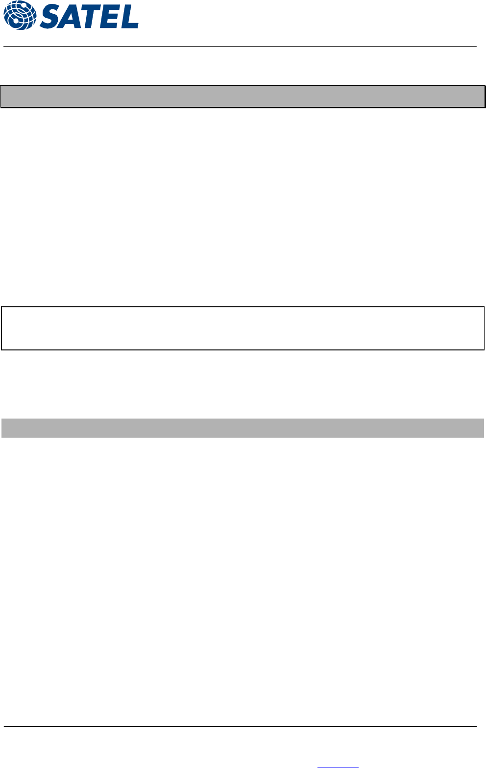
Hereby, SATEL Oy declares that SATELLINE-3AS/TC radio modem is in compliance with the
applicable essential requirements (Article 3.2) and other relevant provisions of Directive
1999/5/EC.* Therefore the equipment is labelled with the following CE-marking. The notification
sign informs user that the operating frequency range of the device is not harmonised throughout
the market area, and the local spectrum authority should be contacted in prior of use.
0523
* The conformity to EMC and Safety requirements (Article 3.1(a)-(b)) of the Directive 1999/5/EC
shall be declared by the original equipment manufacturer in the final device assembly.
ANNEX to SATELLINE-3AS User Guide
SATELLINE-3AS/TC
02.12.2004 (v.1.0)
Page 4 of 11
SATEL Oy, P.O.Box 142, FIN-24101 Salo, Finland
Street: Meriniitynkatu 17, FIN-24100 Salo, Finland
Tel: +358 2 777 7800, Fax: +358 2 777 7810, E-mail: info@satel.fi
www.satel.fi
TABLE OF CONTENTS
IMPORTANT NOTICE ............................................................................................. 1
RESTRICTIONS ON USE ......................................................................................... 2
PRODUCT CONFORMITY........................................................................................ 3
TABLE OF CONTENTS ............................................................................................ 4
1 INTRODUCTION ........................................................................................... 5
2 TECHNICAL SPECIFICATIONS ...................................................................... 6
3 USER INTERFACE.......................................................................................... 7
3.1 LED indicators ............................................................................................ 7
3.2 SL commands ............................................................................................. 8
3.3 Free Channel Scanning feature (FCS) ....................................................... 9
4 HEADER INTERFACE.................................................................................. 10
4.1 Header connector..................................................................................... 10
5 RF INTERFACE ............................................................................................ 11
5.1 Antenna connector................................................................................... 11

ANNEX to SATELLINE-3AS User Guide
SATELLINE-3AS/TC
02.12.2004 (v.1.0)
Page 5 of 11
SATEL Oy, P.O.Box 142, FIN-24101 Salo, Finland
Street: Meriniitynkatu 17, FIN-24100 Salo, Finland
Tel: +358 2 777 7800, Fax: +358 2 777 7810, E-mail: info@satel.fi
www.satel.fi
1 INTRODUCTION
SATELLINE-3AS/TC is a member of the versatile SATELLINE-3AS radio modem family.
Consisting of a data modem and a UHF radio transceiver, it provides a wireless, transparent and
half-duplex serial data link with other similar radio modules or compatible SATELLINE radio
modems manufactured by SATEL Oy.
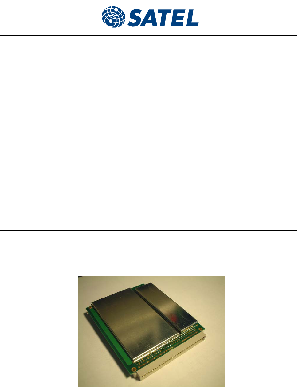
SATELLINE-3AS/TC is designed for integration into the terminal equipment. The component
blocks are shielded by metal plates, but the housing and the related mechanics are supplied by
the client. Also the EMC characteristics of the radio module are completed for the combined
equipment.
A number of new SL commands has been implemented to the modem controller software for full
control of the features of SATELLINE-3AS/TC in integrated use.
The implementation of SATELLINE-3AS/TC is based on the widely used SATELLINE-3AS radio
modem – the radio communication and the user interface are similar. The main differences to
SATELLINE-3AS are:
1. SATELLINE-3AS/TC is delivered without the housing – only the two PCBs (the logic board
and the RF board shielded as a one card) are supplied by SATEL
2. Antenna connector is a female MMCX connector.
3. The antenna circuitry of the radio module includes an additional filter on GPS frequencies
in order to avoid any interference to the GPS receivers.
4. The main header is a 32-pin Eurocard connector type B.
5. The operating voltage must be 6.5V…18VDC.
SATELLINE-3AS/TC has two pins in the header connector for controlling the external LED
indicators, the one for the external green LED and the other for the red LED. By different
combination of the LED status, the user of the application device can monitor the status of the
SATELLINE-3AS/TC radio module.
ANNEX to SATELLINE-3AS User Guide
SATELLINE-3AS/TC
02.12.2004 (v.1.0)
Page 6 of 11
SATEL Oy, P.O.Box 142, FIN-24101 Salo, Finland
Street: Meriniitynkatu 17, FIN-24100 Salo, Finland
Tel: +358 2 777 7800, Fax: +358 2 777 7810, E-mail: info@satel.fi
www.satel.fi
2 TECHNICAL SPECIFICATIONS
SATELLINE-3AS/TC complies with the following international standards:
• EN 300 113
RADIO TRANSCEIVER
Frequency Range 380...470 MHz
Channel Spacing 12.5 kHz/25 kHz
Number of Channels 160 / 80 or (2 x 160 / 2 x 80)
Frequency Stability < ± 1.5 kHz
Type of Emission F1D
Communication Mode Half-Duplex
RADIO TRANSMITTER
Carrier Power 10 mW...1 W / 50 Ω
Carrier Power Stability + 2 dB / - 3 dB
Adjacent Channel Power according to EN 300 113
Spurious Radiations according to EN 300 113
RADIO RECEIVER
Sensitivity - 116... –110 dBm (BER < 10 E-3) depending on Receiver settings
Common Channel Rejection > - 12 dB
Adjacent Channel Selectivity > 60 dB @ 12.5 kHz, > 70 dB @ 25 kHz
Intermodulation Attenuation > 65 dB
Spurious Radiations < 2 nW
MODEM
Interface RS-232
Interface Connector 32-pin Eurocard connector type B
Data Speed of Serial Interface 1200 – 38400 bps
Data Speed of Radio Interface 19200 bps (25 kHz channel) / 9600 bps (12.5 kHz channel)
Data format Asynchronous RS-232
GENERAL
Operating Voltage +6.0...+14.0 VDC
Power Consumption (average) 1.7 VA (Receive)
5.5 VA (Transmit)
0.05 VA (in Standby Mode)
Operating Temperature Range -25 °C...+55 °C
Vibration Not specifed
Antenna Connector MMCX, 50 Ω, female
Housing SATELLINE-3AS/TC is delivered without the housing. The component
blocks on the PCB are covered by metal shields
Size H x W x D 13 x 100 x 123.5 mm
Weight 140 g
ANNEX to SATELLINE-3AS User Guide
SATELLINE-3AS/TC
02.12.2004 (v.1.0)
Page 7 of 11
SATEL Oy, P.O.Box 142, FIN-24101 Salo, Finland
Street: Meriniitynkatu 17, FIN-24100 Salo, Finland
Tel: +358 2 777 7800, Fax: +358 2 777 7810, E-mail: info@satel.fi
www.satel.fi
3 USER INTERFACE
The user interface of SATELLINE-3AS/TC is basically similar to the standard SATELLINE-3AS radio
modem – the data handling, configuration or the control of the device.
The user guide of SATELLINE-3AS raio modem provides the detailed functional description of
SATELLINE-3AS/TC. Only the details specifically applied for SATELLINE-3AS/TC and its use in the
client’s system are specified in this document.
3.1 LED indicators
SATELLINE-3AS/TC has two pins (GRN_LED and RED_LED) in the header connector for
controlling the external LED indicators. GRN_LED controls the external green LED and RED_LED
controls the external red LED.
The radio module itself does not have any LED indicators.
The operation of the LED indicators is different in the “normal” mode and in the FCS (Free
Channel Scan) mode. The operation is specified by the two tables below.
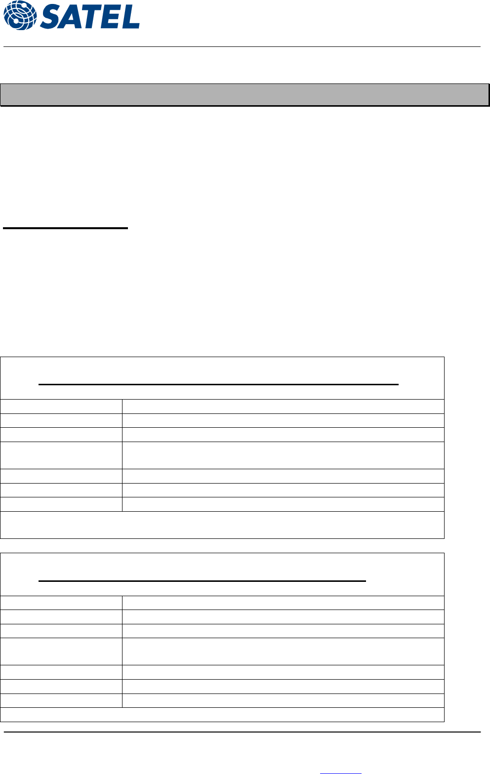
3.1.1 SATELLINE-3AS/TC – LED INDICATORS in the NORMAL MODE
LED status Description
No light Modem is turned off
Green flashes Modem is in receiver mode
Solid green (non-blinking)
Radio Link established. Modem has received data within last 5
seconds
Solid green + red blinks Modem is receiving data
Solid red Modem is in transmitter mode
Red blinks + green blinks Modem is in command mode
Note: In Normal operation all modems are in receiver mode by default, and red led is on only
during the transmission of data.
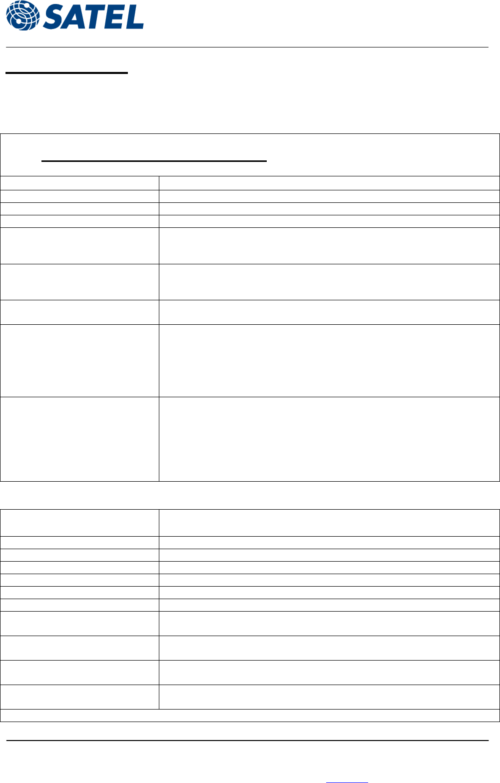
3.1.2 SATELLINE-3AS/TC – LED INDICATORS in the FCS MODE
LED status Description
No light Modem is turned off
Green flashes Modem is in receiver mode
Solid green (non-blinking)
Radio link established. Modem is ready to receive data.
FCS Slave modem has found the transmitter.
Solid green + red blinks Modem is receiving data
Solid red Modem is in transmitter mode
Red blinks + green blinks Modem is in command mode
Note: In FCS mode FCS master modem is always in transmitter mode.
ANNEX to SATELLINE-3AS User Guide
SATELLINE-3AS/TC
02.12.2004 (v.1.0)
Page 8 of 11
SATEL Oy, P.O.Box 142, FIN-24101 Salo, Finland
Street: Meriniitynkatu 17, FIN-24100 Salo, Finland
Tel: +358 2 777 7800, Fax: +358 2 777 7810, E-mail: info@satel.fi
www.satel.fi
3.2 SL commands
SATELLINE-3AS/TC accepts the same SL commands as SATELLINE-3AS. The table below lists all
commands available.
3.2.1 SATELLINE-3AS – SL COMMANDS LIST
Frequency related Effect and description of command
SL&F=nnn.nnnnn Set frequency to nnn.nnnnn MHz
SL&F? Display current frequency (response 'nnn.nnnnn MHz')
SL&C? Display center frequency (response 'nnn.nnnnn MHz')
SL&+=nn Set frequency nn channels above center frequency
Frequency = Center frequency + nn * Channel spacing, where
nn=[0...Number of channels/2]
SL&-=nn Set frequency nn channels below center frequency
Frequency = Center frequency – nn * Channel spacing, where
nn=[0…Number of channels/2]
SL&N?
Display current frequency deviation from center frequency as channels
(Frequency – Center frequency)/Channel spacing (response ‘+nn’ or ‘-nn’)
SL&D=x Sets the operational mode of the radio. The different values of x are:
”S” = Single Channel
”D” = Dual Channel
”R” = Reverse Dual Channel
Note! Use this command only, if the setup of the frequency bands matches the
Dual Channel operation.
SL&D?
Request the operational mode of the radio. The response is one of the
following:
”S” = Single Channel
”D” = Dual Channel
”R” = Reverse Dual Channel
Note! Use this command only, if the setup of the frequency bands matches the
Dual Channel operation.
Addressing related Effect and description of command
(These commands are NOT applicable in this application)
SL#I=xxxx Set all addresses (RX1, RX2, TX1, TX2) to value xxxx
SL#I? Display both primary addresses (TX1, RX1) (response ’xxxx;yyyy’)
SL#T=xxxx Set both transmit addresses (TX1, TX2) to value xxxx
SL#T? Display primary transmit address (TX1) (response ‘xxxx’)
SL#R=xxxx Set both receive addresses (RX1, RX2) to value xxxx
SL#R? Display primary receive address (RX1) (response ‘xxxx’)
SL#P=xxxx;yyyy Set primary transmit address (TX1) to value xxxx and receive address (RX1) to
value yyyy
SL#S=xxxx;yyyy Set secondary transmit address (TX2) to value xxxx and receive address (RX2) to
value yyyy
SL#P? Display primary transmit address (TX1) and receive address (RX1)
(response ‘xxxx;yyyy’)
SL#S? Display secondary transmit address (TX2) and receive address (RX2)
(response ‘xxxx;yyyy’)
Note: xxxx and yyyy above mean address in the hexadecimal format (0000 … FFFF)
ANNEX to SATELLINE-3AS User Guide
SATELLINE-3AS/TC
02.12.2004 (v.1.0)
Page 9 of 11
SATEL Oy, P.O.Box 142, FIN-24101 Salo, Finland
Street: Meriniitynkatu 17, FIN-24100 Salo, Finland
Tel: +358 2 777 7800, Fax: +358 2 777 7810, E-mail: info@satel.fi
www.satel.fi
Other radio related Effect and description of command
SL@R? Display field strength of the last received message (the value is an average of
many measurements made during the same reception).
Response ”-xx dBm”, where xx is a decimal value of the field strength and it is
between –80 dBm and –118 dBm. Value available 7s after reception.
SATELLINE-3AS Epic returns the stronger value of two receivers.
SL@P=xxxxx Set the RF output power, where xxxxx is the decimal value of the intended
power in milliwatts. If the given value does not correspond to one of the
programmed power levels, the output power is set to the nearest possible
value.
SL@P? Requests the RF output power.
Response ”xxxxx mW”, where xxxxx is a decimal value the output power of the
transmitter.
SL@T=-xxx Set the minimum power level of the signal to be received (="Signal Treshold
level), where xxx is a decimal value of the new intended level in dBm.
SL@T? Request of the current "Signal Treshold Level". Response is "-xxx dBm.
FCS related Effect and description of command
SL!M? Show the FCS mode of the modem. The reply is ‘O’ if FCS is turned OFF, ‘M’
for a master (=transmitter) and ’S’ for the slave (=receiver).
SL!O? Returns beacon sending disable timeout
SL!O= Sets the beacon sending disable timeout. Time is in seconds. If it is zero then
beacon is never disabled.
If timeout is less than beacon timeout, modem will not send additional
beacons.
SL!D? Returns the lower limit for band 1
SL!U? Returns the upper limit for band 1
SL!W? Returns the lower limit for band 2
SL!Y? Returns the upper limit for band 2
Other SL commands Effect and description of command
SL**> Save current settings as permanent settings
SL!V? Returns modem type:
• "3AS"
• "3AS(d)"
• "3AS/TC" (for the transceiver module)
• "3ASrm" for receiver module.
SL%V? Display software revision information (response ’Vn.nn’)
SL+P=xxxx Get the measured signal strength from the remote modem i.e. SL “ping”.
(NOT applicable in D-GPS application)
3.3 Free Channel Scanning feature (FCS)
A separate document describes the operation of the Free Channel Scan feature in details.
ANNEX to SATELLINE-3AS User Guide
SATELLINE-3AS/TC
02.12.2004 (v.1.0)
Page 10 of 11
SATEL Oy, P.O.Box 142, FIN-24101 Salo, Finland
Street: Meriniitynkatu 17, FIN-24100 Salo, Finland
Tel: +358 2 777 7800, Fax: +358 2 777 7810, E-mail: info@satel.fi
www.satel.fi
4 HEADER INTERFACE
4.1 Header Connector
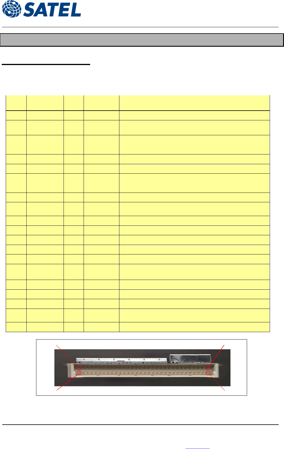
SATELLINE-3AS/TC - HEADER CONNECTOR PINOUT
Type of the connector: 32-pin male Eurocard connector, type B
Pin# Signal Name In/Out Level Description
A1 GND - GND
A3 PWR_ON In 0..+14VDC Radio modem On/Off control
( OFF = 0...+0.7VDC, ON = higher than +2.0VDC).
A6 PROG In 0..+14VDC Must be normally UNCONNECTED or higher than +3.0 VDC
Connect to ground in order to: a) access the setup menu
b) update the program flash
A14 PWR_LED Out High Z / +5V POWER LED anode
A15 RD_LED Out High Z / +5V RD LED anode
A17 GND - GND
A23 PWR_IN In + 6.0..14VDC Power Supply
A24 PWR_IN In + 6.0..14VDC Power Supply
A25 FLASH In 0..+14VDC Must be normally UNCONNECTED. Connected to PWR_IN in order to
enter the FLASH bootmode programming.
A31 RSSI Out 0..+4.5VDC RSSI analog output (option)
B1 GND - GND
B3 TX_A In RS-232 Data FROM terminal unit TO radio modem Port 1
B5 RTS_A In RS-232 Request To Send FROM terminal unit. Radio modem ignores this.
B8 RX_A Out RS-232 Data TO terminal unit FROM radiomodem Port 1
B9 CTS_A Out RS-232 Clear To Send. This signal indicates that radiomodem is ready to receive
data FROM terminal unit.
B11 TX_B In RS-232 Data FROM Hiper TO radio modem Port 2
B13 RTS_B In RS-232 Request To Send FROM terminal unit. Radio modem ignores this.
B16 RX_B Out RS-232 Data TO terminal unit FROM radio modem Port 2
B17 CTS_B Out RS-232 Clear To Send. This signal indicates that radiomodem is ready to receive
data FROM terminal unit.
B24 GND - GND
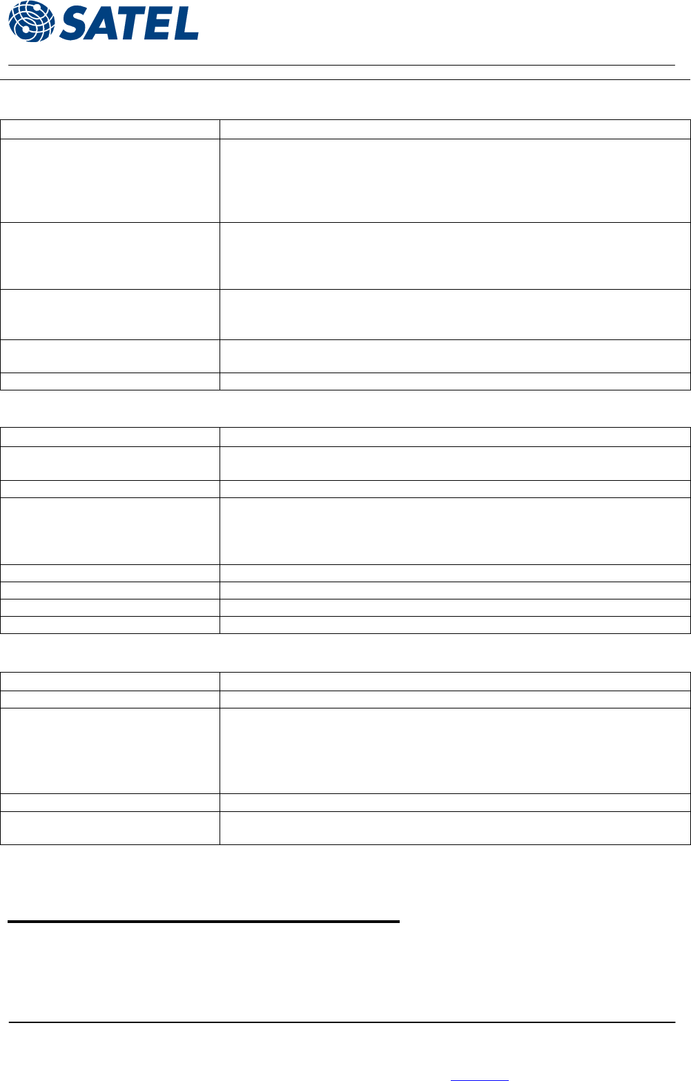
A1
B1
A32
B32
Outside view of the header connector.
ANNEX to SATELLINE-3AS User Guide
SATELLINE-3AS/TC
02.12.2004 (v.1.0)
Page 11 of 11
SATEL Oy, P.O.Box 142, FIN-24101 Salo, Finland
Street: Meriniitynkatu 17, FIN-24100 Salo, Finland
Tel: +358 2 777 7800, Fax: +358 2 777 7810, E-mail: info@satel.fi
www.satel.fi
5 RF INTERFACE
5.1 Antenna connector
The antenna connector is a coaxial 50 ohm MMCX receptable, and it is located on the opposite
side of the module than the header connector.