Sato Vicinity CL4NX-MR-1 MR-1 Module RFID Read Write Reader User Manual
Sato Vicinity Pty Ltd MR-1 Module RFID Read Write Reader Users Manual
Users Manual

Page 1 of 16
EMC Technologies Pty Ltd
ABN 82 057 105 549
Unit 3/87 Station Road
Seven Hills NSW 2147 Australia
Telephone +61 2 9624 2777
Facsimile +61 2 9838 4050
Email syd@emctech.com.au
www.emctech.com.au
Melbourne
176 Harrick Road
Keilor Park, Vic 3042
Tel: +61 3 9365 1000
Fax: +61 3 9331 7455
Sydney
Unit 3/87 Station Road
Seven Hills NSW 2147
Tel: +61 2 9624 2777
Fax: +61 2 9838 4050
Brisbane
1/15 Success Street
Acacia Ridge Qld 4110
Tel: +61 7 3875 2455
Fax: +61 7 3875 2466
Auckland (NZ)
47 MacKelvie Street
Grey Lynn Auckland
Tel: +64 9 360 0862
Fax: +64 9 360 0861
APPENDIX L
OF
TEST REPORT T150916
USER MANUAL
FCC ID:
2ACXQ-CL4NX-MR-1
Manufacturer:
Sato Vicinity Pty Ltd
Test Sample:
RFID Modular Read Write Reader
Model Number:
MR-1 Module
Serial Number:
Production Prototype
Date:
10
th
February 2016

Micro Reader MR-1
OEM Installation Manual
Document Number : 090-01-002-DOC Rev A1
Last Changed : 2 March 2016
Author : Tai Wai Pong
Copyright SATO Vicinity 2016
Commercial in Confidence
Micro Reader MR-1 OEM Installation Manual i 090-01-002-DOC A1 02-Mar-16
Table of Contents
1.
Overview ...................................................................................................................................... 1
2.
Features and Benefits ................................................................................................................... 2
3.
Specifications ............................................................................................................................... 2
4.
Dimensions................................................................................................................................... 3
5.
Connections .................................................................................................................................. 4
5.1
J1 - Host Connector ............................................................................................................... 4
5.2
J2 - Antenna Connector ......................................................................................................... 4
6.
SATO CL4NX Printer PJM RFID Module Installation............................................................... 5
Micro Reader MR-1 OEM Installation Manual ii 090-01-002-DOC A1 02-Mar-16
FCC Radio Frequency Interference Statement (USA)
The FCC regards RFID equipment as low-power transmitting devices and, therefore,
does not require users of RFID devices to obtain a license to operate them.
NOTE: This equipment has been tested and found to comply with the limits for a Class B
digital device, pursuant to Part 15 of the FCC Rules. These limits are designed to provide
reasonable protection against harmful interference in a residential installation. This
equipment generates, uses, and can radiate radio frequency energy and, if not installed
and used in accordance with the instruction manual, may cause harmful interference to
radio communications. However, there is no guarantee that interference will not occur in
a particular installation. If this equipment does cause harmful interference to radio or
television reception, which can be determined by turning the equipment off and on, the
user is encouraged to try to correct the interference by one or more of the following
measures:
• Reorientation or relocation of receiving antenna
• Increase the separation between the equipment and receiver
• Connect the equipment into an outlet on a circuit different from that to which the
receiver is connected
• Consult the dealer or an experienced radio/TV technician for help
Any changes or modifications to the equipment that are not expressly approved by the party
responsible for compliance could void the user’s authority granted under FCC Rules to
operate this equipment.
The following sentence has to be displayed on the outside of the device in which the
transmitter module is installed: “Contains FCC ID: 2ACXQ-CL4NX-MR-1”
The following criteria shall be observed to comply with the regulation:
• Module is limited to OEM installation ONLY
• OEM integrators is responsible for ensuring that the end-user has no manual
instructions to remove or install the module
• Module is limited to installation in mobile or fixed applications
• Separate approval is required for all other operating configurations
ISO/IEC 18000 – 3 Mode 2 (Air Interface at 13.56 MHz)
Compliance
MR-1 module fully comply with the ISO/IEC18000 Part 3 Mode 2(Information technology –
Radio frequency identification for item management. Part 3: Parameters for air interface
communications at 13.56MHz) published in August, 2004.
Micro Reader MR-1 OEM Installation Manual 1 090-01-002-DOC 02-Mar-16
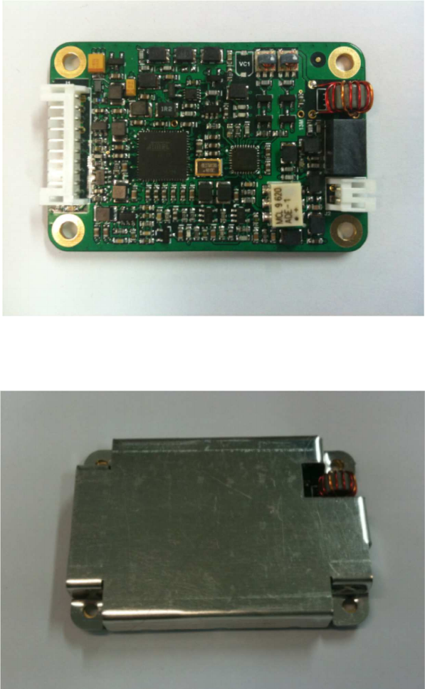
1. Overview
The MR-1 is the smallest and simplest of Magellan’s reader modules. It is intended for
Original Equipment Manufacturer (OEM) applications where it is typically embedded in an
RFID enabled product.
Examples include printers, hand held readers, data capture terminals, low cost desktop
readers, identification and access controls.
Figure 1: MR-1 Module Rev B1
Figure 2: MR-1 Module Rev B1 with Shielding Can

Micro Reader MR-1 OEM Installation Manual 2 090-01-002-DOC 02-Mar-16
2. Features and Benefits
•
Low power module easy to build into RFID enabled equipment.
•
Small footprint.
•
Simple Serial UART interface.
•
Simple Antenna connection.
3. Specifications
Electrical
Operating Frequency 13.56MHz
ISO/IEC Compliance ISO/IEC 18000-3 Mode 2
Command Data Rate 424 kbit/s
Reply Data Rate 106 kbit/s
Number of Reply Channel 1 (Channel ‘G’)
Number of Axes 1
Power Supply +5.0 ± 0.5Vdc
Power Supply Current 200mA max
Host
Host Interface Serial UART
Communications Protocol
Baud Rate Configurable (9600 default)
Parity None
Data Bits 8
Stop Bits 1
Environmental
Operating Environment Indoor use – embedded
applications
Temperature Range 0°C to +70°C ambient
Humidity 10% to 80% (non-
condensing)
Mechanical
External Dimensions: (L x W
x H) 60 x 40 x 12.5 mm
Other Features
Calibration and Tuning No manual calibration or
tuning required
Micro Reader MR-1 OEM Installation Manual 3 090-01-002-DOC 02-Mar-16
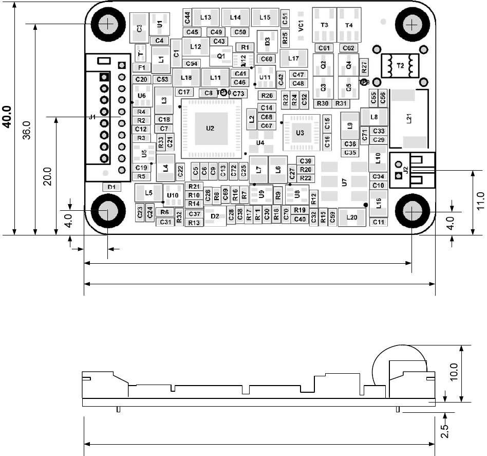
4. Dimensions
4.0
56.0
60.0
60.0
Figure 3 : Major Module Dimensions (mm)
Mounting Holes 4x 3.2 mm diameter

Micro Reader MR-1 OEM Installation Manual 4 090-01-002-DOC 02-Mar-16
5. Connections
5.1 J1 - Host Connector
Connector Type 10 pin (JST Model S10B-PH-K-S)
Reference: http://www.jst-mfg.com/product/pdf/eng/ePH.pdf
Pin Number Function
1 +5 Vdc
2 +5 Vdc
3 Ground
4 Ground
5 RxD UART Receive Signal (+5V TTL/
+3.3V LVCMOS) Input to module.
6 TxD UART Transmit Signal (+5V CMOS)
Output from module.
7 Not Connected
8 Not Connected
9 Not Connected
10 Not Connected
5.2 J2 - Antenna Connector
Connector Type 2 pin (JST Model S2B-PH-K-S)
Reference: http://www.jst-mfg.com/product/pdf/eng/ePH.pdf
Pin Number Function
1 RF
2 Ground

Micro Reader MR-1 OEM Installation Manual 5 090-01-002-DOC 02-Mar-16
6. SATO CL4NX Printer PJM RFID Module Installation
TECHNICAL BULLETIN 0016 r1 – CONFIDENTIAL!
Bulletin Number: 0016 r1
Issue: SATO CL4NX Printer PJM RFID Module Installation
Date: 16 October 2015
Author: Steve Antonio
Prerequisite: SATO CL4NX Printer, PJM RFID Module Kit a and PC with internet access
Severity: General Guide Intended for SATO Qualified Technicians
Affected Range: SATO CL4NX Printers Requiring PJM RFID
Notes:
1. This bulletin is confidential and intended for internal use by SATO staff ONLY – DO NOT share
this document externally!
2. This bulletin is intended for SATO qualified technicians with a working knowledge of the
CL4NX printer, as such rudimental steps like “Remove fixing screws” or “open print head” are
implied & have been omitted from this document!
3. Due to ongoing development/improvements some of the items/Versions listed in this bulletin
may vary from those shown!
4. Ensure your PJM RFID kit contains all parts listed on the “CL4NX + PJM RFID: PARTS LIST” on
page 2 of this document.
5. Ensure you read & fully understand this document prior to undertaking any installation work.
Tools Required: Size 1 Philips Head Screwdriver, 5mm nut driver.
Micro Reader MR-1 OEM Installation Manual 6 090-01-002-DOC 02-Mar-16
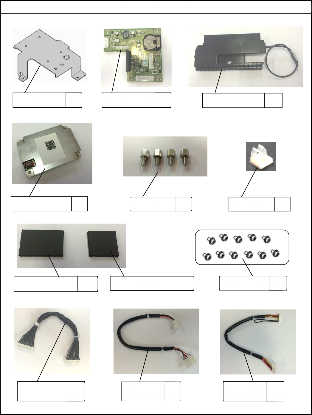
CL4NX + PJM RFID: PARTS LIST
P55186000
RFID MODULE BR
1
R28518001
EXT PCB ASSY
1
090
-
50
-
0001
-
ASY
-
1
CL4NX PJM ANTENNA ASSY
1
090
-
10
-
001
-
ASY
MR
-
1 Module
1
098
-
02
-
056
-
FST
SPACER M/F 3x6mm
4
JG100511A
MINI CLAMP
1
090-50-0002-HAW-1
FLEXIBLE FERRITE 28x17x2mm
1
090
-
50
-
0003
-
HAW
-
1
FLEXIBLE FERRITE 17x17x2mm
1
098
-
01
-
052
-
FST
SEMS M3x6mm S/W
11
R28824000
EXT SIGNAL
CABLE SET
1
R28431000
EXT POWER
CABLE SET
1
R29836001
RFID SIGNAL
CABLE SET
1
Micro Reader MR-1 OEM Installation Manual 7 090-01-002-DOC 02-Mar-16
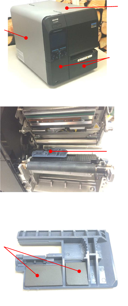
Action:
1. Remove the 3 covers form the printer - these are the left side cover & the 2 front bottom covers (see
Image 1), then open the Right side cover.
Image 1
2. Locate and remove the Label-sensor-guide-SUB (see Image 2).
Image 2
3. Fit the two sections of flexible Ferrite (Part Numbers: 090-50-0002-HAW-1 & 090-50-0003-HAW-1)
that are supplied in the kit to the Label-sensor-guide-SUB by peeling the backing paper and pasting
them in place as shown in Image 3.
Image 3
4. Remove the original Media-guard in order to fit the replacement guard (PN: 090-50-0001-ASY-1) that
is supplied in the kit.
5. Fit the new Media-guard paying particular attention to the routing on the Antenna cable as follows:-
Step 1. Pass the antenna cable through the existing hole in the engine-frame as shown in Image 4
Front bottom covers x 2
Left side cover
Right side cover
Label-sensor-guide-SUB
Flexible Ferrite sections fitted
to label-sensor-guide-SUB
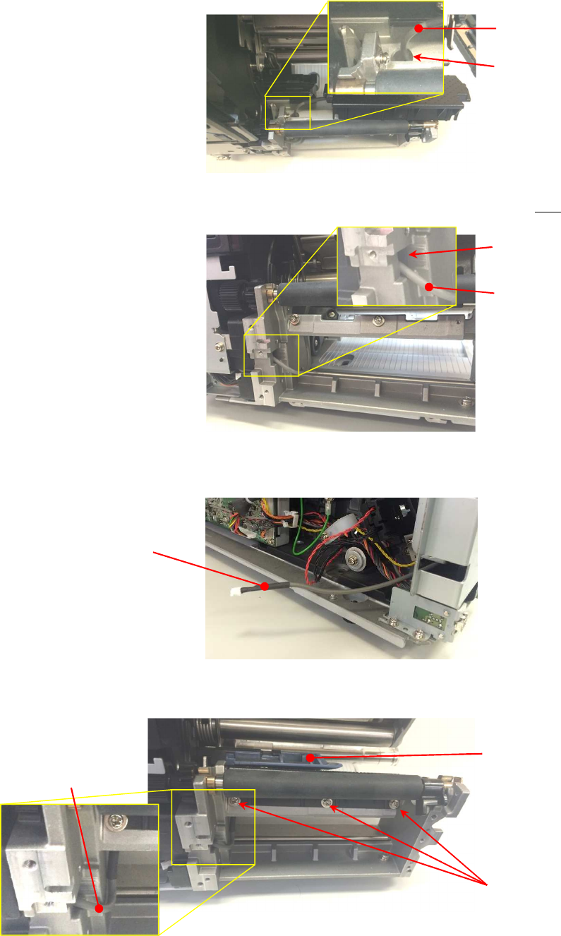
Micro Reader MR-1 OEM Installation Manual 8 090-01-002-DOC 02-Mar-16
Image 4
Step 2. Route the antenna cable through the second existing “Square” hole in the side of the
engine-frame as shown in Image 5
Image 5
Step 3. Pull the antenna cable through into the Electronics area of the printer as you lower the
new Media-guard into place. See Image 6
Image 6
6. Now secure the Media-guard back in place using the original 3 screws & re-fit the Label-sensor-guide-
SUB. Ensure the Antenna cable is routed close to the engine-frame. See image 7
Image 7
7. Locate the RFID module bracket (PN: P55186000) and fit the 4 x 3x6mm spacers (PN: 098-02-056-
FST) and the mini clamp (PN: JG100511A). As shown in Image 8
Existing hole in
the engine-frame
Antenna Cable
Antenna Cable
Existing hole in the
engine-frame side
Antenna Cable
Label-sensor-guide-SUB
3 screws securing the
Media-guard in place
Antenna Cable
routed close to
engine-frame
Micro Reader MR-1 OEM Installation Manual 9 090-01-002-DOC 02-Mar-16
Image 8
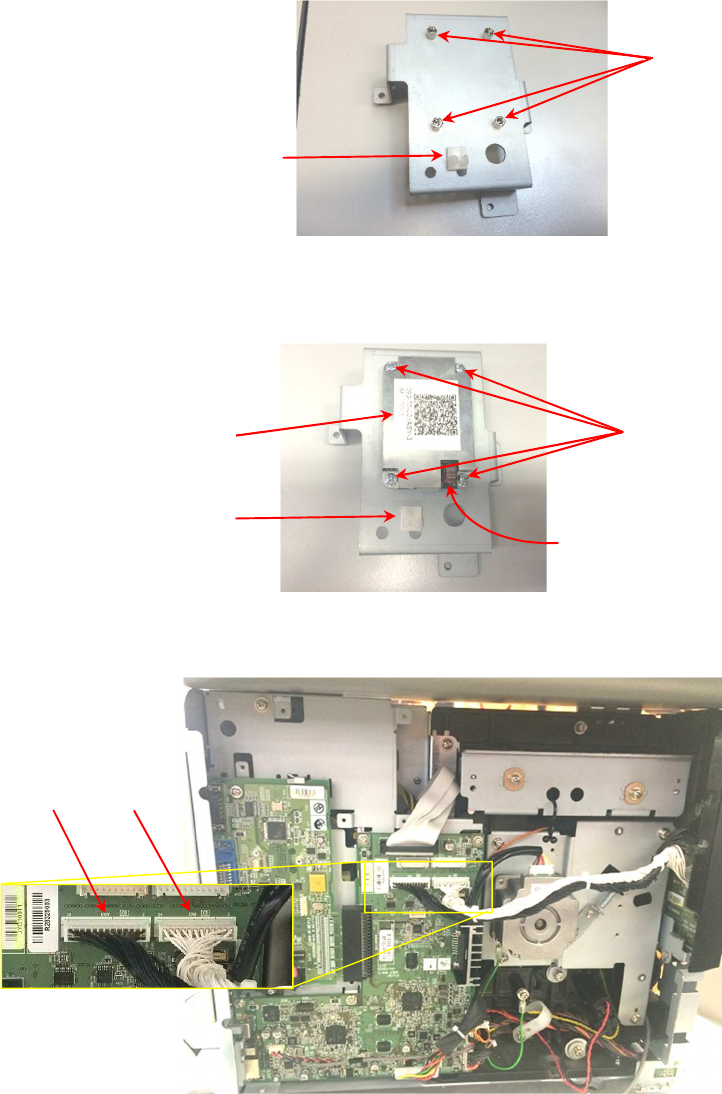
8. Fit the RFID module (PN: 090-10-001-ASY) to the RFID module bracket using 4 of the 3x6mm screws
provided (PN: 098-01-052-FST). The RFID module is fitted to the spacers you fitted at step 7. Note the
orientation of the RFID module with the toroid transformer facing the mini clamp. See Image 9
Image 9
9. In order to facilitate fitment of the RFID hardware in to the printer, carefully disconnect the harnesses
from locations CN17 & CN6 on the printer main board, moving them aside temporarily. See image 10
Image 10
10. Fit the RFID Module bracket to the printer using 3 of the 3x6mm screws provided (PN: 098-01-052-
FST). See image 11
4 x 3x6mm spacers
Mini Clamp
RFID module fitted to
RFID module bracket
4 off 3x6mm screws
CN 17 CN6
Toroid transformer
Mini Clamp
Micro Reader MR-1 OEM Installation Manual 10 090-01-002-DOC 02-Mar-16
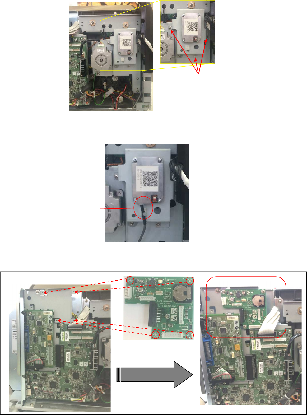
Image 11
11. Connect the Antenna cable to the RFID module clipping the cable into the mini clamp, note the cable is
keyed & will only fit in one orientation. See Image 12
Image 12
12. Fit the EXT PCB ASSY board (PN R28518001) to the printer using 4 of the 3x6mm screws supplied.
See image 13.
Image 13
13. Install the RFID Signal Cable set (PN:R29836001) from the RFID module to the EXT PCB ASSY board
-location CN5. The cable connectors are keyed so please observe the connector orientation. NOTE:
The connector with the loop wire is connected to the EXT PCB ASSY board. See Image 14
3 off 3x6mm Screws
EXT PCB ASSY board fitted to printer
Antenna cable
connected to the
RFID module

Micro Reader MR-1 OEM Installation Manual 11 090-01-002-DOC 02-Mar-16
Image 14
14. Connect the EXT Power cable set (PN:R28431000) from the EXT PCB ASSY – CN4 to the power
supply connector J4. See Image 15
Image 15
15. Fit the EXT SIGNAL CABLE SET (PN:R28824000) from the EXT PCB ASSY – CN3 to the printer main
board CN4. See Image 16
Image 16
16. Reconnect the 2 harnesses to locations CN17 & CN6 on the printer main board that were disconnected
at step 9. See Image 17
Loop wire end connects to
EXT PCB ASSY – CN5
EXT PCB
ASSY – CN4
Power
Supply J4
connector
behind
EXT PCB
ASSY
View from above the printer
EXT PCB
ASSY – CN4
EXT PCB ASSY – CN3
Printer main
board – CN4
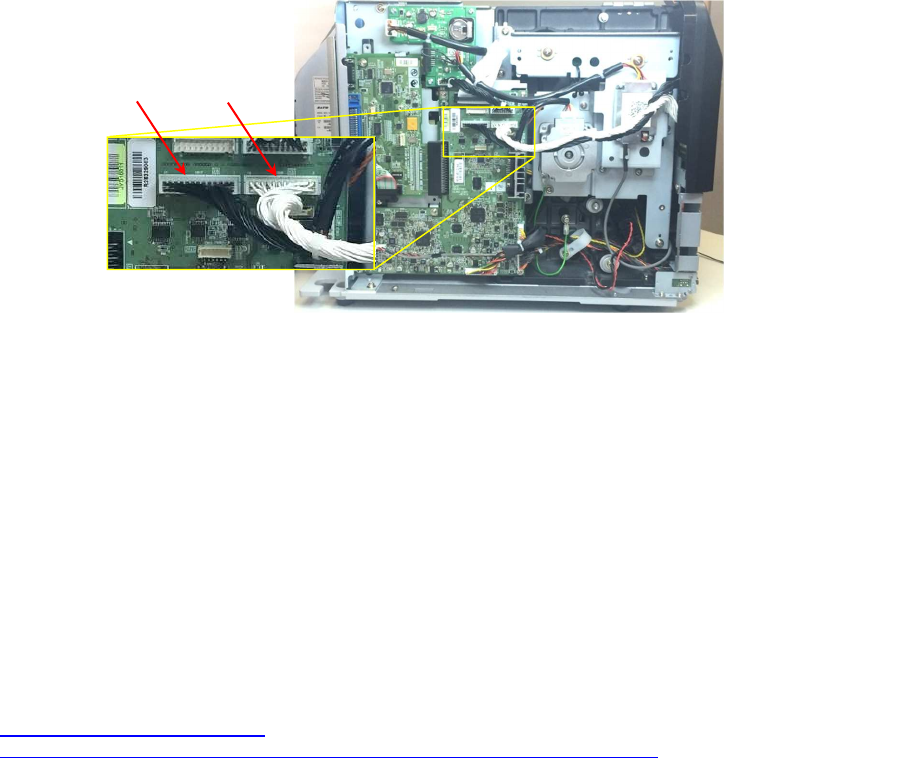
Micro Reader MR-1 OEM Installation Manual 12 090-01-002-DOC 02-Mar-16
Image 17
17. Re-fit the left side cover & the 2 front bottom covers to the printer.
Printer Firmware update:
The printer firmware will need to be updated to the current PJM RFID compatible version. T
he firmware
update process is a two step process as follows:-
Step 1) Update the printer base firmware to Version
1.4.1-r1 following the instructions found in SATO
document “STL00191PA5_FWアップデート手順書Firmware update manual”
Step 2)
The second step is to upgrade the base printer firmware using the PJM firmware package
“
update_s01_PJM_01A” again following the instructions found in SATO
document “STL00191PA5_FWアップデート手順書Firmware update manual”
The SATO firmware update manual as well as the firmware installation files (1.4.1-r1
& update_s01_PJM_01A) are available for download from the following link: -
https://drive.google.com/a/sato-
global.com/folderview?id=0B7okyWbH6BrNc1J1U1dMS2VvYzQ&usp=sharing
©2015 SATO Vicinity. All rights reserved. Specifications subject to change without notice. Any unauthorized reproduction of the contents
of this presentation, in part or whole, is strictly prohibited. SATO is a registered trademark of SATO Holdings Corporation and its
subsidiaries in Japan, the U.S. and other countries. All other trademarks are the property of their respective owners.
CN17 CN6