Sato Vicinity MARS-1 MARS-1 DESKTOP READER User Manual users manual
Sato Vicinity Pty Ltd MARS-1 DESKTOP READER users manual
Contents
- 1. reader manager guide
- 2. users manual
users manual
HF RFID System
User Manual
MARS-1-2-4-6
Multiple Antenna Reader-Writer Systems
Document Number : 64-70-017-DOC
Last Changed : 04 October 2006
Copyright Magellan Technology 2006
Commercial in Confidence

Content
1. INTRODUCTION ------------------------------------------------------------------------------------------------------------------- 3
1.1 REGULATION AND STANDARDS .......................................................................................................................................... 3
1.2 WARRANTY ................................................................................................................................................................... 4
1.3 LIMITATION OF LIABILITY ................................................................................................................................................. 4
1.4 CHANGES IN PRODUCT FAMILY, SPECIFICATIONS AND USER MANUALS/GUIDES ....................................................................... 4
1.5 COPYRIGHTS AND COPY PERMISSION .................................................................................................................................. 4
1.6 MEANING OF ALERT SYMBOLS AND SIGNAL WORDS ........................................................................................................... 5
1.7 GLOSSARY OF TERMS AND ABBREVIATIONS ........................................................................................................................ 6
2. PRODUCT OVERVIEW ---------------------------------------------------------------------------------------------------------- 8
2.1 MARS-1 ...................................................................................................................................................................... 8
2.2 MARS-2 ...................................................................................................................................................................... 8
2.3 MARS-4 ...................................................................................................................................................................... 9
2.4 MARS-6 ...................................................................................................................................................................... 9
3. BEFORE YOU BEGIN ----------------------------------------------------------------------------------------------------------- 10
3.1 UNPACKING AND INSPECTION .......................................................................................................................................... 10
3.2 INSTALLATION ENVIRONMENT ......................................................................................................................................... 12
3.3 RECOMMENDED SYSTEM REQUIREMENTS .......................................................................................................................... 12
3.4 INSTALLATION REQUIREMENTS ........................................................................................................................................ 13
3.5 ANTENNA MAINTENANCE (TUNING) ................................................................................................................................ 16
3.6 WORKING WITH TAGS .................................................................................................................................................... 18
3.7 TAG-TO-ANTENNA ORIENTATION .................................................................................................................................... 20
4. INSTALLATION ------------------------------------------------------------------------------------------------------------------ 21
4.1 HARDWARE INSTALLATION ............................................................................................................................................. 22
4.1.1 Connecting to a power supply ........................................................................................................................... 23
4.1.2 Connecting a Reader to a Computer using USB ............................................................................................... 24
4.1.3 Connecting a Reader to a Computer using Ethernet ........................................................................................ 24
4.1.4 Connecting Multiple Readers to a local network .............................................................................................. 25
4.1.5 Connecting External Antennas .......................................................................................................................... 25
4.1.6 Antenna Matching, Tuning and Testing ............................................................................................................ 26
4.2 READERMANAGER SOFTWARE INSTALLATION .................................................................................................................... 27
4.2.1 Installation and Functionality Test ................................................................................................................... 27
4.3 CONNECTING TO A READER USING READERMANAGER ........................................................................................................ 28
4.3.1 Connecting to a Reader via USB for the first time ............................................................................................ 32
4.3.2 Upgrading software ........................................................................................................................................... 34
4.4 COMMUNICATION TEST .................................................................................................................................................. 35
5. REPORTING A PROBLEM ---------------------------------------------------------------------------------------------------- 36
5.1 TROUBLESHOOTING ........................................................................................................................................................ 38
5.2 SERVICE FORM ............................................................................................................................................................. 40
6. CONTACT US ---------------------------------------------------------------------------------------------------------------------- 41
7. REVISION HISTORY ------------------------------------------------------------------------------------------------------------ 42
8. APPENDIX -------------------------------------------------------------------------------------------------------------------------- 43
8.1 SPECIFICATION .............................................................................................................................................................. 43
8.2 EXTERNAL ANTENNA TYPES ........................................................................................................................................... 44
8.3 READER-TAG COMPATIBILITY ......................................................................................................................................... 46
8.4 MAXIMUM READ-WRITE DISTANCE ................................................................................................................................ 47
MARS-1-2-4-6 USER MANUAL 64-70-017-DOC ver.1
1
Please read before proceeding
Please read and understand this document before
using Magellan’s Readers.
If you have any questions, comments or suggestions about the User Manual please contact
Magellan Technology.
Important Information
Installation Environment
For indoor use only unless otherwise specified.
Install Magellan’s Readers within the temperature and humidity range according to the product
specification.
The environment must not contain corrosive, flammable or explosive agents or be subject to
rapid changes in temperature, to direct vibration or shock.
Installation
Magellan’s RFID reader-writers communicate with data carriers (RFID inlets, labels and tags)
using the 13.56 MHz High Frequency (HF) band. Some industrial machines and electronic
devices can generate unwanted noise which may degrade communication. Make sure that
other equipment is properly installed, grounded and at a reasonable distance from the Reader
and/or Reader antennas.
Wireless communication can be degraded by high-voltage and high-current lines and other
sources of strong electric and magnetic fields. Installation in such locations should be avoided.
!Magellan’s RFID reader-writers are to be professionally installed by authorised,
qualified and service-trained installation personnel only.
Maintenance
All Magellan’s RFID readers-writers are low maintenance equipment. Except for externally
accessible fuses there are no user-serviceable parts in any Reader. There is no requirement to
remove the cover of the Reader.
!Removal of the Reader cover by unauthorised personnel will void the product
warranty.
Do not attempt to clean internally. Periodic cleaning of external case parts with a damp cloth is
advisable. Turn off the Reader before cleaning. Do not use a solvent of any kind.
Electrical Safety
In order to avoid electric shock do not remove the Reader cover
or attempt to repair. The Reader must be maintained by
authorised, qualified and service-trained personnel only.
Environmental
For disposal Readers should be treated as industrial waste.
This symbol on the product or on its packaging indicates that this product shall not be treated
as household waste. Instead it shall be handed over to an appropriate collection point for the
recycling of electrical and electronic equipment. By ensuring this product is disposed of
correctly, you will help prevent potential negative consequences for the environment and
human health, which could otherwise be caused by inappropriate waste handling of this
product. The recycling of materials will help to conserve natural resources. For more detailed
information about recycling of this product, please contact your local city office, your household
waste disposal service or the Magellan Technology regional sales office.
MARS-1-2-4-6 USER MANUAL 64-70-017-DOC ver.1
2
1.Introduction
Thank you for your recent purchase of a Magellan RFID reader-writer.
This User Manual will provide you with information to rapidly adopt
Magellan’s PJM technology for your needs, to install the Reader hardware
and ReaderManager software and get the Reader running.
Refer to the ReaderManager Guide (40-01-006-DOC) for a description of
the various tools and advanced options available in the ReaderManager
software.
Programming is covered in the Application Programmer’s Guide (40-01-000-
DOC).
1.1Regulation and Standards
RFID equipment is subject to national and international regulations.
FCC Radio Frequency Interference Statement (USA)
The FCC regards RFID equipment as low-power transmitting devices and,
therefore, does not require users of RFID devices to obtain a license to
operate them.
NOTE: This equipment has been tested and found to comply with the limits
for a Class B digital device, pursuant to Part 15 of the FCC Rules. These
limits are designed to provide reasonable protection against harmful
interference in a residential installation. This equipment generates, uses,
and can radiate radio frequency energy and, if not installed and used in
accordance with the instruction manual, may cause harmful interference to
radio communications. However, there is no guarantee that interference will
not occur in a particular installation. If this equipment does cause harmful
interference to radio or television reception, which can be determined by
turning the equipment off and on, the user is encouraged to try to correct the
interference by one or more of the following measures:
Reorient or relocate of receiving antenna
Increase the separation between the equipment and receiver
Connect the equipment into an outlet on a circuit different from that to
which the receiver is connected
Consult the dealer or an experienced radio/TV technician for help
!Any changes or modifications to the equipment that are not
expressly approved by the party responsible for compliance
could void the user’s authority granted under FCC Rules to
operate this equipment.
FCC ID: TVN-Mars-1
Industry Canada Radio Frequency Interference Declaration of Conformity (Canada)
This Class A digital apparatus complies with Canadian ICES-003.
Cet appareil numérique de la classe A est conforme à la norme NMB-003
du Canada.
ICES\NMB-003 IC: 6596A-Mars1
MARS-1-2-4-6 USER MANUAL 64-70-017-DOC ver.1
3
Other regulations
EU
ETSI EN 300 330-1 v.1.3.1 (2001-06)
ETSI EN 300 330-2 v.1.2.1 (2004-11)
ETSI EN 489-1 v.1.5.1 (2004-11)
ETSI EN 489-3 v.1.4.1 (2002-08)
EN 61000-3.2: 2002
EN 61000-3.3: 1995
Safety: IEC/EN 60950
Pending
AS/NZS CISPR 22: 2004
4268: 2003 Pending
ISO/IEC 18000 – 3 Mode 2 (Air Interface at 13.56 MHz) Compliance
Magellan’s Readers fully complies with the ISO/IEC 18000 Part 3 Mode 2
(Information technology – Radio frequency identification for item
management. Part 3: Parameters for air interface communications at 13.56
MHz) published in August, 2004.
1.2Warranty
Magellan’s warranty and liability with respect to products and/or services is
for a period of 12 months from date of delivery and is limited to the
rectification of faulty workmanship and/or non-compliance by Magellan.
Any liability with respect to components including purchased or free issued
items and other materials used in the manufacture of products are covered
by, and limited to, any warranty provided by the original manufacturer.
1.3Limitation of Liability
Magellan’s warranty excludes products that have been improperly installed
or maintained, modified or misused. Notification of claims must occur within
the warranty period.
End-users should contact the company from whom they purchase the
products for replacement, repair or refund.
If purchases the Reader directly from Magellan, contact Magellan for a
Return Authorization Number (RAN) before shipment.
1.4Changes in Product Family, Specifications and User
Manuals/Guides
This document is subject to change without notice in future editions.
Magellan reserves the rights to change its product design, specifications
and product range.
1.5Copyrights and Copy Permission
This document shall not be copied, reproduced or transmitted in any form or
by any means without written permission from Magellan Technology Pty
Limited. This document is protected by copyrights and is intended solely for
use in conjunctions with Magellan’s products only.
MARS-1-2-4-6 USER MANUAL 64-70-017-DOC ver.1
4
1.6Meaning of Alert Symbols and Signal Words
Notes and Tips. Application Notes.
!This part of the Manual requires your attention.
! CAUTION
Indicates a potentially hazardous situation which,
if not avoided, will result in minor or moderate
injury. Can cause property damage.
! WARNING
Indicates a potentially hazardous situation which,
if not avoided, will result in minor or moderate
injury, or may result in serious injury or death.
Can cause significant property damage.
Warning!
In order to avoid electric shock follow the
instructions provided.
MARS-1-2-4-6 USER MANUAL 64-70-017-DOC ver.1
5

1.7Glossary of Terms and Abbreviations
Antenna A Reader antenna that emits radio waves and
receives reply signals from tags. The Reader
antenna can be internal which is integrated into
the Reader and external which is connected to
the Reader via a cable.
Antenna axis The antenna port on the Reader antenna
interface the antenna is plugged into.
Antenna tuning Trimming a reader antenna to its highest
possible field strength which corresponds to the
highest operating voltage.
Create axis group Create an antenna group. It means to combine
antennas or antenna ports in one group that
serve the same purposes or applications.
Configure axis group Configure group antenna behaviour. It means to
set up all antennas in the group to the same
behavioural parameters which will be default
parameters for this group.
D/C Date Code (month/year)
DSB Digital Support Board
HDF High Density Fiberboard (for MARS only)
HF High Frequency
GUI Graphical Use Interface
IT ItemTag (chips, inlets and labels)
ItemTag tags (IT tags) Magellan’s labels and inlets for item tagging
(separated items) that work with Magellan’s
family of reader-writers
LAN Local Area Network
LED Light Emitting Diode
MDF Medium Density Fiberboard (for MARS only)
MLC Machine Level Control (System Configuration
Control)
MRD Maximum Read-Write Distance
Network Connections
window
In Windows XP open Start-> Control Panel->
Network Connections or open My Computer->
Other Places-> My Network Places-> View
Network Connections
OEM label Original Equipment Manufacture label is located
on the back of the equipment. It includes the
Model Number, P/N, D/C, S/N and MLC.
PJM Phase Jitter Modulation or PJM™ is a registered
Trade Mark of Magellan Technology Pty Limited.
PJM is a RFID communication technology
developed and patented by Magellan
Technology Pty Ltd and complies with ISO/IEC
18000-3 Mode 2. PJM technology products
include a range of RFID chips, inlets, tags and
Readers.
PJM ItemTag® Registered Trade Mark for Magellan’s ItemTag
tags
PJM StackTag® Registered Trade Mark for Magellan’s StackTag
tags
P/N Part Number
MARS-1-2-4-6 USER MANUAL 64-70-017-DOC ver.1
6

Power cycle the PC Shut up Windows and switch the PC off at the
wall and wait for 30 seconds before powering
the PC back up again. For laptops this means
removing the battery and waiting for 30 seconds.
This ensures that the USB host controller chips
on the motherboard have had a chance to be
fully reset.
Power cycle the
Reader
Turn off the power or unplug the power cable
(the power port on the Reader user interface).
Open the Network Connections window in
Windows. Wait for the Reader’ network
connection to be removed from the Network
Connections window. Plug the Reader back and
wait for the network connection to re-appear and
become Connected in the Network Connections
window. Connect to a Reader via the
ReaderManager’s Connection menu.
Reader/s Magellan’s RFID reader-writer/s
ReaderManager Graphical user application for Windows/Linux
which provides a platform for testing,
demonstrations and application development
ReaderServer Embedded application that provides the
standard Application Programmer Interface to
serve end-user applications. This application
runs on the Reader.
RFID Radio Frequency IDentification
RFID inlet A RFID device comprising a microchip and a
printed antenna (copper/aluminium/conductive
inks) on a flexible substrate (PET plastic film)
RFID label RFID inlet with adhesive backing (sticky label)
RFID tag 1. generic name for RFID inlet and label;
2. RFID inlet or label inserted into a
housing (glass, polycarbonate,
polyamid, epoxy, ABS, etc.)
RFID reader-writer Device for reading and writing to RFID tags
RMA Return Authorisation number
Setup axis Setup antenna. To setup an antenna means to
match the antenna with its corresponding
antenna port by choosing the antenna type from
list in the ReaderManager.
S/N Serial Number
ST StackTag (chips, inlets and labels)
StackTag tags
(ST tags)
Magellan’s labels and inlets for item tagging
(stacked, touched or overlapping items) that
work with Magellan’s family of reader-writers
MARS-1-2-4-6 USER MANUAL 64-70-017-DOC ver.1
7
2.Product Overview
Intended use of Magellan’s RFID Reader is to read and write information to
individual Magellan ItemTags and multiple Magellan StackTags.
The communication protocol used by the Reader is compliant with ISO/IEC
18000 - 3 Mode 2 (Air Interface at 13.56 MHz).
MARS-1-2-4-6 family of the Readers comprises MARS-1, MARS-2, MARS-4
and MARS-6 reader-writers.
2.1MARS-1
Multiple Antenna Reader System – 1
Operates with a single antenna
2 reply channels
2.2MARS-2
Multiple Antenna Reader System – 2
Operates with up to 2 antennas
2 reply channels
MARS-1-2-4-6 USER MANUAL 64-70-017-DOC ver.1
8
2.3MARS-4
Multiple Antenna Reader System – 4
Operates with up to 4 antennas
2 reply channels
2.4MARS-6
Multiple Antenna Reader System – 6
Operates with up to 6 antennas
2 reply channels
MARS-1-2-4-6 USER MANUAL 64-70-017-DOC ver.1
9
3.Before you begin
3.1Unpacking and Inspection
When you receive your system, inspect it for any
obvious damage that may have occurred during
shipment. If there is damage, notify the shipping
carrier and the supplier of the equipment or
Magellan if purchase directly from Magellan.
Until you have checked the system, save the
shipping carton and packaging materials in the
event the unit has to be returned.
The standard MARS package includes the following components:
Reader-writer
External antennas and connection RCA cables
MARS Model Name Number of External
Antennas
Number of RCA
Cables
MARS-1 1 1
MARS-2 Up to 2 Up to 2
MARS-4 Up to 4 Up to 4
MARS-6 Up to 6 Up to 6
Power adaptor
USB data communication cable
Quick Start Guide
CD-ROM
Test tag/s (required for Hardware Functionality Test and
Communication Test)
Magellan Antenna Tuning Kit (optional)
Power Pack
The Reader connection to the power source is realized via a low voltage
power pack (12VDC output).
!A power cable is not included. End-users should purchase a
power cable suitable for the country of use.
! CAUTION
Only power cables and adaptors that are
compliant with the regulations in the country of
use may be connected to Magellan’s equipment.
MARS-1-2-4-6 USER MANUAL 64-70-017-DOC ver.1
10
Data Communication Cables
Magellan supplies USB shielded cable (USB 2.0, 2 m long)
!USB cable should not be longer than 3m
!
As shielded cables are generally required in order to comply
with EMC emissions limits, the shielded cables recommended
by Magellan Technology must be used. Unshielded cabled
may be used where explicitly allowed in the Installation
Requirements section of this User Manual.
Ethernet cable is not included with the supply.
Magellan recommends CAT5 Ethernet cable.
CD-ROM
The CD-ROM contains the following files:
AdbeRdrxx_enu_full.exe Self-extracting installation kit for the
Adobe Acrobat reader, which is
required to read and print PDF files
40-01-000-DOC
Application Programmer
Guide.pdf
PDF document describing how to
program all of Magellan’s Readers
40-01-006-DOC
ReaderManager Guide
PDF document describing various tools
and advanced options available in
ReaderManager software
64-70-017-DOC
User Manual.pdf
PDF version of this document
ReaderManager-Install.exe Self-extracting installation kit for the
ReaderManager
Once you install the ReaderManager software the
User Manuals and Guides can be open in
Windows:
Start -> (All) Programs -> Magellan Technology ->
User Manuals.
MARS-1-2-4-6 USER MANUAL 64-70-017-DOC ver.1
11
3.2Installation Environment
Magellan’s Readers are designed to operate in indoor environments where
temperature and humidity are controlled unless other conditions are
specified for customised Readers.
For standard Readers the temperature range is from +10oC to +45oC. The
humidity range is from 10% to 80% (non-condensing humidity).
Install the Readers within the temperature and humidity ranges according to
the product specification.
The environment must not contain corrosive, flammable or explosive agents
and conductive dust or be subject to rapid changes in temperature, direct
vibration or shock.
! WARNING Do not operate this Reader in an environment
which contains flammable or explosives gases or
fumes.
Magellan’s RFID reader-writers communicate with data carriers (RFID inlets,
labels and tags) using the 13.56 MHz High Frequency (HF) band. Some
industrial machines and electronic devices can generate unwanted noise
which may degrade communication. Make sure that other equipment is
properly installed, grounded and are at a reasonable distance from the
Reader and/or Reader antennas.
Wireless communication can be degraded by high-voltage and high-current
lines and other sources of strong electric and magnetic fields. Installation in
such locations should be avoided.
In order to avoid electric shock do not remove the Reader
cover or attempt to repair. Magellan’s reader-writers are to
be maintained by authorised, qualified and service-trained
personnel only.
!Removal of the Reader cover by unauthorised personnel will
void the product warranty.
3.3Recommended System Requirements
Recommended minimum host computer requirements:
Operating System: Windows XP SP2
Memory: 128MB RAM
Hard Drive: 20 GB
CPU: Intel Celeron 500
Interface: USB or Ethernet
MARS-1-2-4-6 USER MANUAL 64-70-017-DOC ver.1
12
3.4Installation Requirements
Power supply requirements:
Mains input: 110 - 240 VAC @ 50/60 Hz
Low voltage input (MARS-1-2-4-6): 12 VDC @ 1.5 A
MARS Readers require special installation and tuning of external antenna/s.
Refer to the ReaderManager Guide (40-01-006-DOC) for the antenna
matching, tuning and testing instructions using the Reader Setup Wizard
tool.
The MARS model number corresponds with the maximum number of
external antennas that can be connected to the MARS Reader.
MARS’ external antennas are suitable for applications where one or many
reading points are required. They are designed to be embedded into desk
tops or shelves.
Once antennas are installed in the position they
are to be used, it is essential that they are fixed in
place and tuned. Tuning is done only once at
installation. All antennas (except the small round
antenna 30 mm radius) have an adjustable
capacitor that allows for tuning.
Materials
The affect of materials and antenna position on antenna operation may be
determined as follows:
Place an antenna on a Styrofoam block and tune
for maximum voltage at the antenna center using
an Antenna Tuning Probe, digital voltmeter and a
trimming tool. Then place the antenna on/into the
installation position, retune and measure the
maximum voltage again. Compare the voltage
values.
A difference of 10% or less is acceptable. If the
voltage reduces more than 10%, this indicates the
material is adversely affecting the antenna. The
user should determine if the reduction in
operation is acceptable by measuring read range
and stacking operation. If the reduction is not
acceptable the antenna may be relocated.
Alternatively use of a plastic spacer of 5 mm
between the mounting material and the antenna is
recommended where the mounting material is
adversely affecting the antenna.
Reader antenna performance may be affected by conductive and metallic
materials in the immediate vicinity of the antenna.
Metal, metallic or metallized objects placed next to the Reader antenna may
change the characteristics of the antenna affecting the tuning operation and
reducing the read range.
It’s recommended that the antenna not to be placed closer than 35 cm to
any metallic object that is of a similar or larger size to the antenna.
Small metallic objects such as jewelry or coins put on the antenna will have
almost no affect on the antenna performance.
MARS-1-2-4-6 USER MANUAL 64-70-017-DOC ver.1
13
If metallic conveyor rollers are a part of an application it’s advised to replace
them with plastic parts if possible or apply shielding techniques as required.
The materials that antennas are mounted on/into should not be metallic or
conductive.
Materials such as wood, laminated MDF, HDF or plywood have a limited
conductivity. If an antenna is mounted into these materials some drop in the
read range is expected in comparison with the equipment specification.
Plastics are the best materials to embed antenna into provided they are
graphite/carbon free.
Try to avoid using black plastics as they may be
conductive due to carbon/graphite based
colouring agents.
Clear glass is generally not conductive and can be used as a desk top
material. Smoked and tinted glass may be conductive and any affect on
antenna operation should be determined by measurement.
Distance
Antennas mounted in a close proximity to each other may interfere with
each other’s operation.
For antennas connected to the same MARS Reader the safe distance
between the antenna edges is antenna size dependent and varies from 5
cm (radius 30 mm round antenna) to 15 cm (202x352 mm antenna).
For antennas connected to two different MARS Readers the safe distance
between the antenna edges is also antenna size dependent and varies from
30 cm (radius 30 mm round antenna) to 60 cm (202x352 mm antenna).
Do not mount an antenna on a desktop surface if there is a MARS reader
immediately below and under the antenna. The distance between the
antenna and the MARS reader should be no less than 20 cm. Use extended
brackets to increase the distance if required. Alternatively the MARS can be
screened from the antenna by a purpose built ferrite shield.
!In general no electronic devices are to be placed within 20 cm
of the antenna in any direction.
Before such installations are attempted Magellan must be
consulted.
Cables
Do not run any cables under or near antenna. Maintain a minimum distance
of 15 cm.
!The cables that connect external antennas with the reader are
provided by Magellan. The MARS Readers should only
operate with antenna cables supplied by Magellan.
!Any changes or modifications to the equipment that are not
expressly approved by the party responsible for compliance
will void the product warranty.
MARS-1-2-4-6 USER MANUAL 64-70-017-DOC ver.1
14

How to shield antennas
Antennas may be shielded by a purpose built ferrite sheet only. In special
circumstances devices such as keyboards and computers may be placed
under antennas where a purpose built ferrite antenna shield (64-50-001) is
provide to protect the antenna.
A ferrite shield consists of a sheet of aluminium with ferrite tiles, minimum
thickness 5 mm.
Contact Magellan for further information on shielding antennas for you
specific application and the specification of the Ferrite Antenna Shield (64-
50-001) when planning your installation.
MARS-1-2-4-6 USER MANUAL 64-70-017-DOC ver.1
15
3.5Antenna Maintenance (Tuning)
Antennas may require periodic re-tuning and testing. Detuning of an
antenna may occur if physical environment around the antenna is changed.
For example when large metal objects are located near the antenna or
electronic devices or cables are placed in close proximity with the antenna.
The severity of detuning is dependent upon the size of the metal object and
can only be determined by measurement.
Before tuning make sure that metal objects, electronic devices and cables
are not closer that the recommended distances in any direction from the
antenna.
The purpose of the tuning procedure is to maintain an antenna at its correct
operating point. Tuning the antenna means to trim it to its highest possible
field strength which corresponds to the highest voltage as measured by a
voltmeter with an Antenna Tuning Probe.
Contact Magellan for further instructions for your specific application.
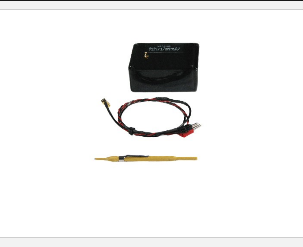
Equipment and Software Required for Antenna Tuning and Testing
1 x Antenna Tuning Probe with cable (Magellan Antenna Tuning Kit)
1 x RF Trimming Tool (Magellan Antenna Tuning Kit)
Antenna Tuning Kit: Antenna Tuning Probe with a cable and RF Trimming Tool
1 x Universal Digital Voltmeter (to measure DC voltages between 1
and 15 volts)
ReaderManager software– V2.05 or better
1 x Tag (fully powered tag)
Tuning Instructions
1. Connect the Antenna Tuning Probe terminals to the voltage and
input terminals of the digital voltmeter.
2. Set the voltmeter to measure a DC voltage range greater than 10
volts.
3. Place the Antenna Tuning Probe in the center of the antenna.
4. Using an RF trimming tool adjust the tuning capacitor on the
antenna for maximum voltage as measured by the tuning probe.
MARS-1-2-4-6 USER MANUAL 64-70-017-DOC ver.1
16

Quality Assurance/ Quality Control
If the maximum read distance is important for
your application then the antennas have to be
protected/shielded from the interference with a
mounting material firstly and then tuned at
maximum voltage.
In case the maximum read distance is not an
issue the antennas can work properly even at
lower voltage but at a reduced read range.
Method 1
To confirm optimum antenna operation measure the maximum read-write
distance.
1. Take a single tag and position it over the Reader antenna center.
Do not hold the tag antenna coil or tag inner area with you fingers.
Preferably hold the tag edges or use a non metallic carrier to hold
the tag.
2. Measure the maximum read distance in mm and compare with the
value for the same antenna-tag type in the Maximum Read-Write
Distance chart. Refer to this User Manual, Appendix.
3. If the maximum read-write distance is less than the chart value re-
tuning may be necessary. If the antenna is correctly tuned then the
user should determine if the reduction in read-write distance is
acceptable.
Method 2
During an initial tuning procedure measure the maximum voltage using an
Antenna Tuning Probe. Record the voltage value for every antenna in the
ReaderManager software. To confirm tuning at any time measure the
maximum voltage using the Antenna Tuning Probe and compare with the
recorded results. The voltage values should be identical otherwise the
antenna has to be tuned.
MARS-1-2-4-6 USER MANUAL 64-70-017-DOC ver.1
17
3.6Working with Tags
Do not stack ItemTags on top of each other. Only
StackTags can be stacked, overlapped or touch
each other.
Single-axis Readers are tag orientation sensitive.
Refer to the Tag-to-Reader/Tag-to-Antenna
section of this document.
Reading and writing speeds depend on reader-
tag communication speeds, the number of
receiver channels, amount of information to be
read and/or written and the number of tags
presented at a time. The additional number of
tags and information to be read and especially
written slows down the read-write communication
speed. Please consult Magellan or your support
organisation regarding these issues for your
specific application.
Be aware that tags and Readers can be
incompatible with each other. Larger tags can
work with all types of Readers. Smaller tags
require higher field strengths and as a result they
may not operate with some Readers or have to be
closer to a Reader antenna to operate. Refer to
the Reader-Tag Compatibility section of this
document.
StackTag tags delivered on a roll are always fully powered (ST normal
power mode or 6000 mode). Fully or normal powered tags are ON all the
time and reply to each Reader command providing they are in the field of
the Reader antenna.
To decrease tag clashing and increase anti-collision and stackability for
some applications the tags can be reconfigured by end-users to a ¼ low
power mode (ST ¼ normal power mode or 2000 mode). This means that
tags in the ¼ low power mode are muted ¾ of the time and do not to reply to
the Reader commands instantly.
Tags can be reconfigured individually (one by one) or on mass (many at
once).
Before reconfiguring tags make sure the
ReaderManager software has been installed and
upgraded to the latest version, the Reader is
running and the Reader is Connected to the
ReaderManager software.
How to reconfigure tags individually or on mass
1. In the ReaderManager go to Tools -> System -> Console. Click with
the right mouse button and tick Show Tag Replies.
2. Then go to Reader Configuration and choose
Config_Normal_Powered_Tag or Config_Quarter_Powered_Tag
(for the ReaderManager version 2.12 or higher).
3. Place a single tag or multiple tags into the reader antenna field.
4. Take the tag/tags off the reader.
5. Follow the step 3 to 4 for a new batch of tags.
6. Once completed go to Reader Configuration and click on Clear All.
MARS-1-2-4-6 USER MANUAL 64-70-017-DOC ver.1
18

How to check a tag configuration mode
1. In the ReaderManager go to Tools -> System -> Interrogate
Command.
2. In Reply select Normal and click Send.
3. Then go to Tools -> System -> Table of Tag Messages to see the
tag configuration in the Config column. The messages of all the tags
currently in the reader antenna field can be seen. 2000 means that
the tag has been reconfigured to ST ¼ normal power mode
configuration. 6000 means that a tag is in ST normal power mode.
MARS-1-2-4-6 USER MANUAL 64-70-017-DOC ver.1
19
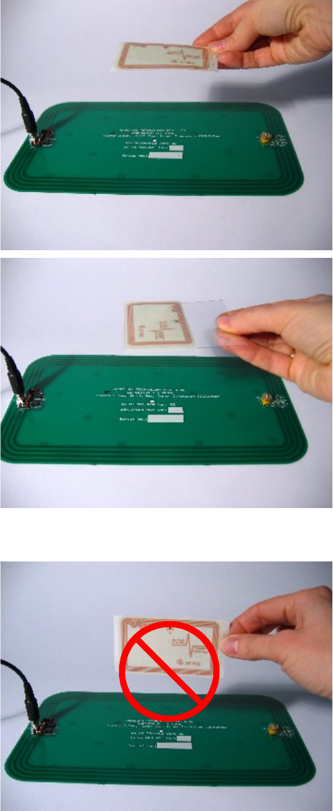
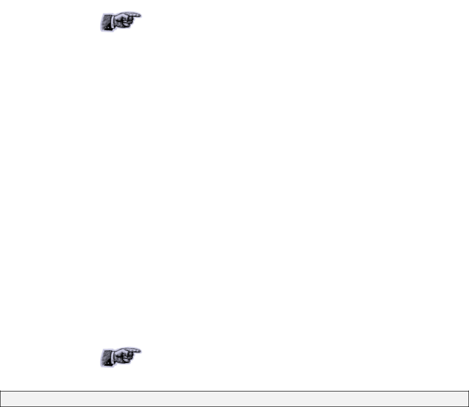
3.7Tag-to-Antenna Orientation
Tags should always be presented face on to the external antenna surface.
They may still work at some angle depending upon the distance between
the tag and the external antenna.
Correct orientation
Incorrect orientation (90o angle)
MARS-1-2-4-6 USER MANUAL 64-70-017-DOC ver.1
20
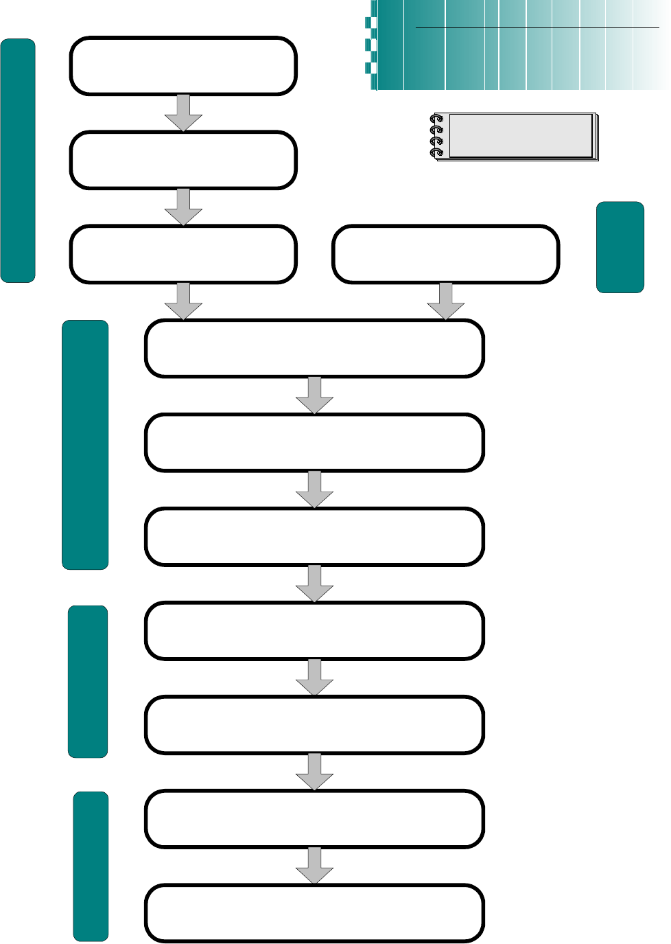
4.Installation
Connect external antenna/s to the
Reader
Install the ReaderManager software
from the supplied CD-ROM
Connect a power pack to the Reader
Open the ReaderManager
Turn on the Reader
Open the Connection menu in the ReaderManager.
Find and click on the Reader you want to connect to.
QUICK START GUIDE
MARS Readers
Open Tools->System->Reader Setup
Use the Reader Setup Wizard to setup Reader-
antenna connection, tune and test antenna/s.
(Refer to the ReaderManager Guide)
HF RFID Readers-Writers
PJM
®
Technology
ISO/IEC 18000-3 Mode 2
Open Tools->System->Grid of Tag Sight Counts.
Place tag/s onto the antenna/s.
Connect a communication cable
(USB or Ethernet) to the Reader
and host PC
Hardware Installation
(4.1 User Manual)
Software
Installation
(4.2 User Manual)
Antenna Matching, Tuning
and Testing
(4.1.6 User Manual)
Tag Reading
(4.4 User Manual)
Connecting to a Reader
using the ReaderManager
(4.3 User Manual)
The tag's ID and the number of times the tags were
sighted will be displayed
MARS-1-2-4-6 USER MANUAL 64-70-017-DOC ver.1
21
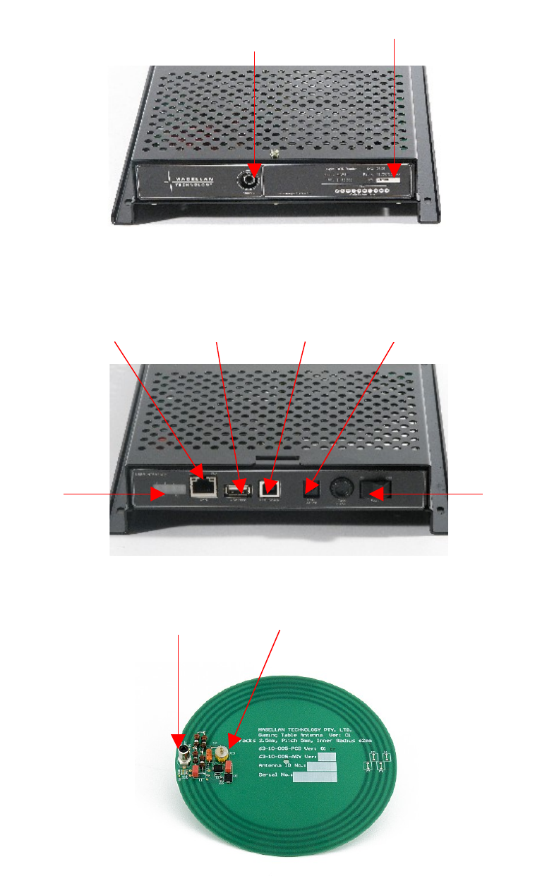
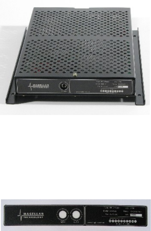
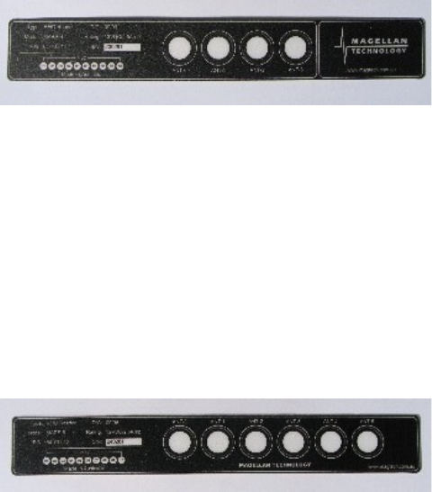
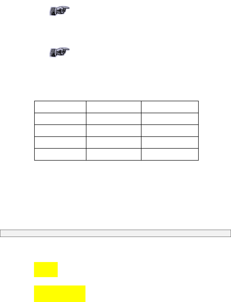
4.1Hardware Installation
MARS-1 Antenna Interface and OEM label panel
MARS User Interface panel
Round 60 mm antenna (63-10-005)
MARS-1-2-4-6 USER MANUAL 64-70-017-DOC ver.1
RJ45
(Ethernet port)
USB
device port
Power port
USB
host port
LEDs
Power
switch
Adjustable tuning capacitor
RCA connector
OEM Label
Antenna Port
22
4.1.1Connecting to a power supply
Step 1. Connect a low voltage power pack to the unit.
The connection to the power source is realized via a low voltage power
pack.
The power cable is not supplied with the Reader
and recommended to be purchased in the country
of use.
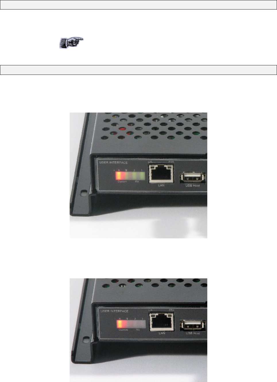
Step 2. Plug the power supply into AC power mains. LEDs will come on.
When power is applied to an MARS Reader the LEDs on the Reader should
operate as follows:
the red LED and green LED will immediately come on; both LEDs will
go off in about 1 minute
MARS with the red and green LEDs on
the red LED will come on again in 1-3 seconds indicating that the
Reader is in an operational mode; the green LED will be off
MARS with the red LED. The Reader is in an operational mode
MARS-1-2-4-6 USER MANUAL 64-70-017-DOC ver.1
23
once the unit is in an operational mode the red LED will remain lit the
green LED will flash every time a tag/tags is/are successfully read
LEDs are controlled by the MARS Reader
software
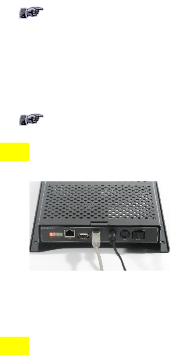
4.1.2Connecting a Reader to a Computer using USB
Connect the MARS Reader to a host computer using the USB data
communication cable by plugging the USB cable into the MARS USB device
port and the host computer USB port.
Only one Magellan Reader can be connected to
the PC via USB at a time (limited by Windows).
!When the USB connection is used only a screened USB cable
should be used.
MARS with the USB communication cable and power cable
4.1.3Connecting a Reader to a Computer using Ethernet
Connect the MARS Reader to a host computer using a cross over Ethernet
cable. Plug the Ethernet communication cable into the MARS RJ45 socket
(Ethernet port) and the network interface port on the PC.
!Always connect Ethernet cable before power is applied to the
Reader.
MARS-1-2-4-6 USER MANUAL 64-70-017-DOC ver.1
24
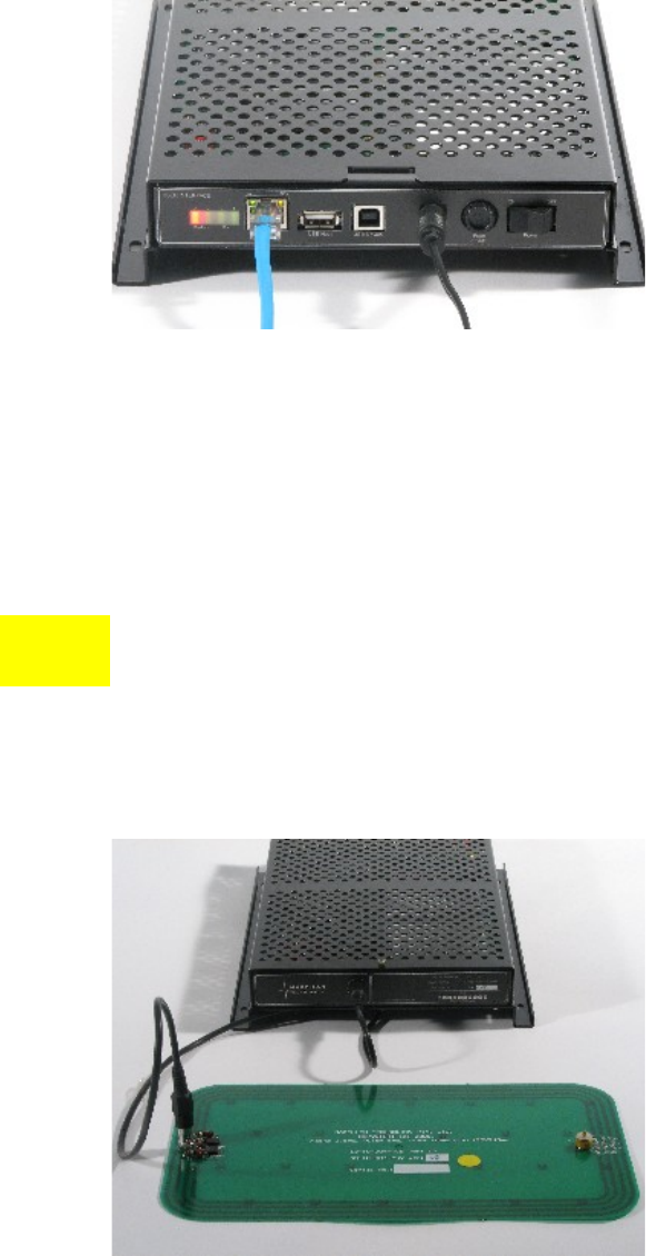
MARS-1 with the Ethernet communication cable and power cable
4.1.4Connecting Multiple Readers to a local network
Multiple Readers can be connected to a local network using an Ethernet
hub/switch. Plug the Ethernet communication cable into the MARS’s RJ45
socket (Ethernet port) and Ethernet Hub.
!Always connect Ethernet cable before power is applied to the
Reader.
4.1.5Connecting External Antennas
Connect each external antenna to a Reader’s Antenna Axis/port via a
supplied RCA connection cable.
MARS-1 with the external 120x240 mm antenna connected
MARS-1-2-4-6 USER MANUAL 64-70-017-DOC ver.1
25

4.1.6Antenna Matching, Tuning and Testing
Before you start tuning and testing the antennas
it’s required to install the ReaderManager
software and connect to a Reader in the
ReaderManager’s Connection menu.
Refer to the ReaderManager Guide (40-01-006-DOC) for the antenna
matching, tuning and testing instructions using the Wizard tool in Reader
Setup.
Follow the procedure, making sure that the
Magellan Antenna Tuning Probe and voltmeter
are used to measure when the tuning is correct.
The design of the antenna and the selection of
the correct cable length is a critical factor in the
reliability of a reader. Each antenna has unique
set up values associated with it that are used by
the software to ensure the reader and antenna
are matched to each other.
The most critical part of the setup of MARS-2, MARS-4 and MARS-6 is
telling the reader what type of antenna is connected to each antenna axis
(Setup Axis).
This is done using the Reader Setup tool in the Reader Manager. It provides
a fixed list of antennas with known set up values for that particular Reader.
If an antenna is not listed in this table it cannot be used with that Reader.
Unless correct set up values are measured by Magellan and recorded in the
list of known antennas, the antenna will not operate properly.
If you can not find your antenna on the list you
have to upgrade the ReaderManger software to
the latest version assuming that you purchased a
new antenna type recently to be used with the
Reader purchased some time before. You will
also need to upgrade the ReaderServer on your
Reader.
Update the ReaderManager from our website
first. Then you can upgrade the ReaderServer
using new version of the ReaderManager
installed.
Note that different release versions (MLC number) of the same Reader may
well have very different set up values, because of circuit changes. The
Reader selection system accounts for this and automatically manages
loading the correct values for a given version of the Reader.
MARS-1-2-4-6 USER MANUAL 64-70-017-DOC ver.1
26
4.2ReaderManager Software Installation
The ReaderManager application software allows tag data to be viewed and
programmed.
The ReaderManager can only connect to one Reader at a time. The
Connections menu allows the user to connect to other Readers by
disconnecting from the currently connected Reader and then establishing a
connection to a new Reader.
It is possible to run many ReaderManagers on the same computer at the
same time. Simply double click on the ReaderManager icon to open up
multiple instances of the ReaderManager.
Refer to the ReaderManager Guide (40-01-006-DOC) for various tools and
advanced options available in the ReaderManager.
4.2.1Installation and Functionality Test
Step 1. Insert the CD supplied with the Reader into the CD-ROM.
Step 2. Open Windows Explorer, double click on ReaderManager-Install.
Step 3. Ensure all the items in Install dialog are ticked, and then click the Install
button.
If Python is not installed on your computer, the installation program will
prompt you if you would like to install Python. Click the Yes button and
accept all the default options during installation.
When the ReaderManager and all the required libraries are installed the
dialog box will be displayed. Ensure the dialog box shows Completed and
no problems are reported.
There is an option to install only an Ethernet-over-
USB driver. Tick only the PJM Reader USB driver
(RNDIS Ethernet) box in Install dialog and press
Install.
Step 4. Click the Close button to continue.
If the ReaderManager is already installed, double click ReaderManager-
Upgrade. Follow steps 3 to 4 above.
If Python and PyQt are already installed, the installation program will not re-
install them. To force the installation program in re-install these libraries,
click the relevant check boxes.
Step 5. To start ReaderManager double click the ReaderManager icon or select
ReaderManager from the Programs Start menu.
Step 6. Functionality test.
From menu select Help>About ReaderManager to see the version of the
ReaderManager software and its status.
MARS-1-2-4-6 USER MANUAL 64-70-017-DOC ver.1
27
4.3Connecting to a Reader using ReaderManager
Magellan’s Readers are complex and powerful
network devices. As most network devices they
should be handled by well trained network
administrators.
A Reader provides Ethernet and USB device interfaces to allow for client
connection. The USB interface uses TCP/IP networking over USB as the
protocol. This allows you to connect to a Reader as if it was a normal
network. So all the usual services, such as telnet and FTP are available.
Step 1. Open the Reader Manager. Ensure a communication cable is plugged in and
a Reader is turned on.
ReaderManager will automatically detect all Readers on the local network.
When a Reader is connected for the first time to a network using an
Ethernet cable or a host computer using a USB cable, the Reader is
identified by its Model Name-Serial Number (recommended to keep).
Customers can replace or add additional
information to the Model Name-Serial Number
such as a physical location or customer ID
number.
Subsequently when a customer starts using the
Reader the new name will appear on the list of
Readers in the Connection menu.
Tip: If you want to use the new name
immediately, simply unplug the power connector
and plug in again to view the new name on the
Connection menu list.
MARS-1-2-4-6 USER MANUAL 64-70-017-DOC ver.1
28
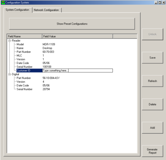
To change a Reader network name:
From the Tools menu, select System then Configuration System. The
window shown below will be displayed.
Click the column on the right of Customer ID and enter the name you would
like the Reader to be identified as. This is the name that will appear on the
Connection menu.
Click the Save button on the right to save your changes to the reader, or
click the Refresh button to restore the previously saved name.
MARS-1-2-4-6 USER MANUAL 64-70-017-DOC ver.1
29
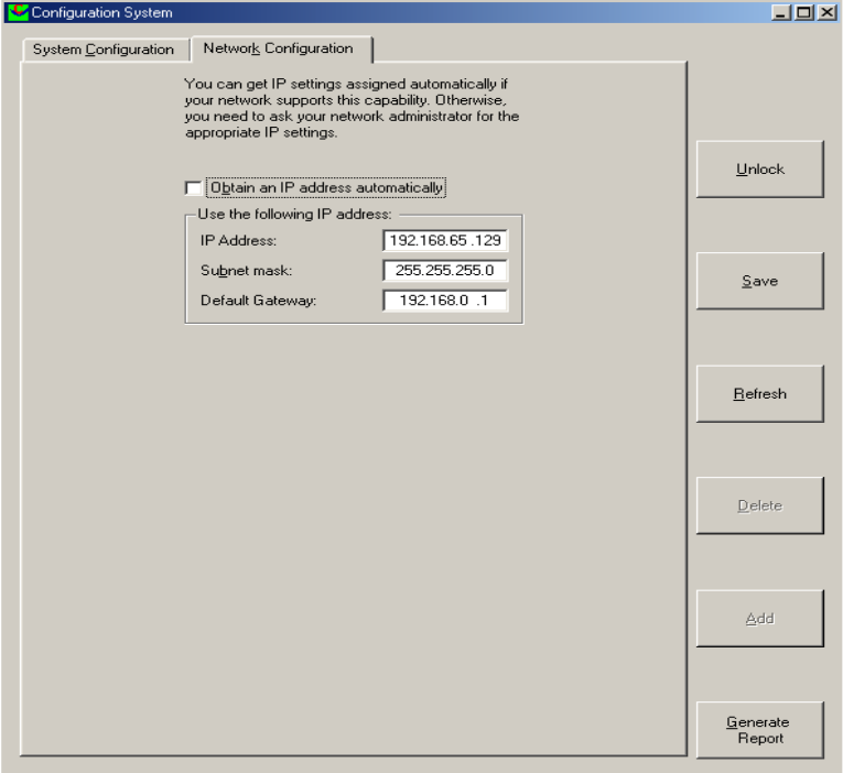
To change the Reader’s network settings:
Click the Network Configuration tab.
If the Reader is to be assigned an IP address from a DHCP server click the
Obtain an IP address automatically check box.
To assign a static IP address, uncheck the check box and enter the IP
address in the IP address text box. The box will turn red if the IP address is
not valid. Care should be taken not to duplicate IP addresses on your
network. If you are unsure what IP address to use consult your systems
administrator.
Enter the network Subnet mask and Default gateway addresses in the text
boxes provided.
Click the Save button to save these changes to the Reader, or click the
Refresh button to restore the last saved values.
Restart the Reader for these changes to take effect.
MARS-1-2-4-6 USER MANUAL 64-70-017-DOC ver.1
30
Here is a general guide to the way reader network
address assignment works:
The Ethernet interface is either served an IP address
via DHCP or is assigned a static IP address by the
user. If the reader is set to use a DHCP assigned
address and no DHCP server is available it will
automatically use a link local address of
169.254.0.0/16.
The reader must be powered up with the Ethernet
connected to get a DHCP assigned IP address.
These are the networking rules:
USB will always choose a subnet different to
Ethernet.
Both interfaces will try to obtain the 169.254.0.0
range, but Ethernet has priority.
172.16.0.0/16 is USB's fallover subnet if Ethernet
has already taken it by either: DHCP, fixed, or link-
local IP acquisition.
Step 2. Click the Connection menu item to view Readers found on the local
network.
The ReaderManager will use network broadcasts to look for active readers
via USB and Ethernet. If you click on the Connection menu, you can see
readers defined in there automatically.
A list of Readers will be displayed. The IP address and MAC address will be
shown on the status bar as you move the mouse over each Reader entry.
Step 3. To connect to a Reader, select the Reader you would like to connect to from
the Connection menu, then click the left mouse button.
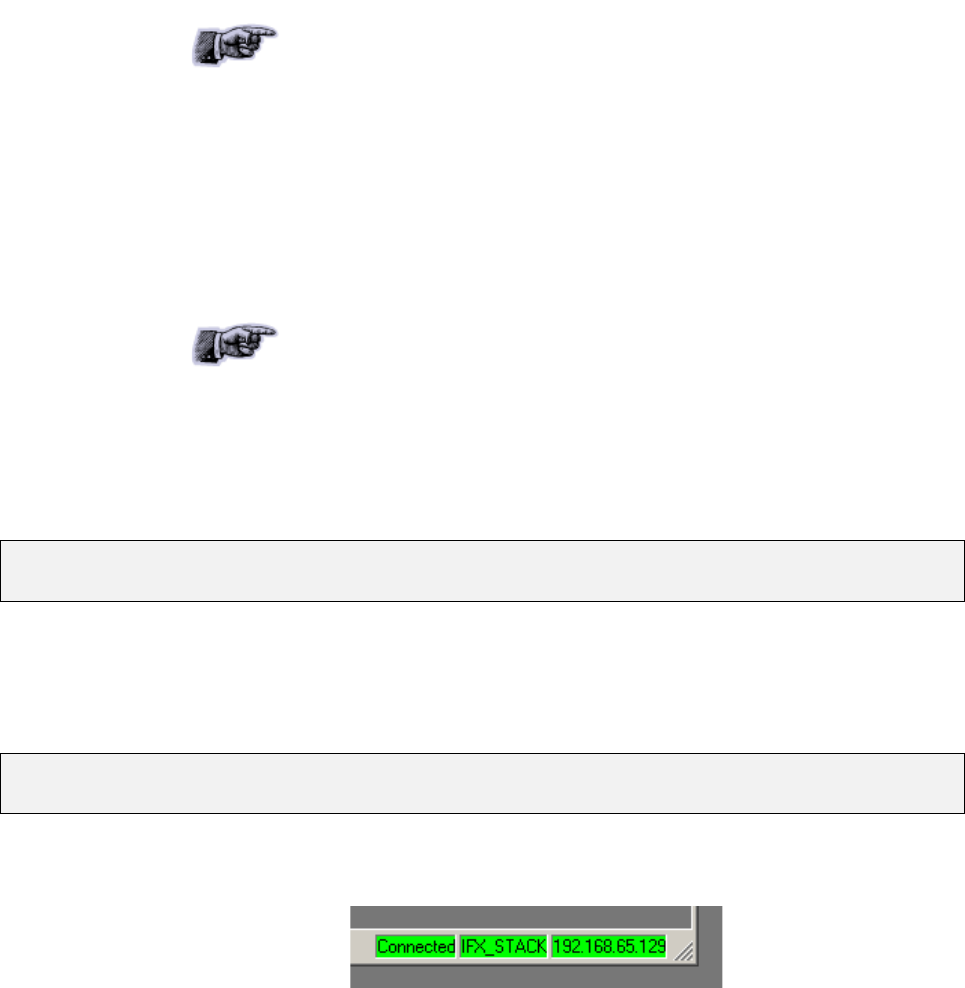
The status bar will change from a red to a green background to indicate that
the ReaderManager was able to connect to a Reader. The tag type and IP
address are also shown on the status bar.
To get more information how to setup static connections to Readers refer to
the ReaderManager Guide (40-01-006-DOC).
MARS-1-2-4-6 USER MANUAL 64-70-017-DOC ver.1
31

4.3.1Connecting to a Reader via USB for the first time
Any device hardware when it’s first connected to a PC via USB requires a
device driver. The device driver is provided by Microsoft. No USB device
drivers are available instantly. They have to be installed and require a
certain amount of configuration. The driver must be installed on the PC
before Windows can use the connection. The device driver is installed on
the PC via the ReaderManager.
When you install a new Reader for the first time it
can take from 1 to 5 minutes to create a network
connection before the ReaderManager is able to
recognize a new Reader.
Since every Reader has a unique serial number, Windows treats it as a new
device and you will have to install the device driver again for each new
Reader that you connect to the one PC. Since the device driver files are
already on the Reader, Windows can search for the driver automatically.
In order to connect to a Reader via USB for the first time follow the steps
below:
Step 1. Open Network Connections in Windows to view the network connection
process.
You can verify that the reader is connected by looking at the Network
Connections window. You can open this window from several places: Start
-> Control Panel -> Network Connections or My Computer -> Other Places
-> My Network Places -> View Network Connections.
Step 2. Open the ReaderManager. Plug in the USB and power cables. Turn on the
Reader. The Found New Hardware dialog box will be displayed.
When a Reader is connected to a host computer for the first time using a
USB, these are a few steps to go through before the ReaderManager is able
to identify a new Reader:
1. In Found New Hardware Wizard tick Yes, this time only to search
for software and press Next.
2. In What do you want wizard to do? tick Install the software
automatically and press Next.
3. Wait while the wizard installs the Linux USB Ethernet/RNDIS
Gadget device driver. Ignore other message and press Continue
anyway.
4. Press Finish.
Step 3. Wait until you see a new entry appears in the Network Connections list
called “Linux USB Ethernet/RNDIS Gadget”. This is the Reader.
If it says Acquiring IP address then you must wait until it says Connected.
The Reader’s network connection will say:
1. Local Area Connection X
2. Connected
3. Linux USB Ethernet/RNDIS Gadget
Once it says Connected in the Network Connections window (Windows XP
SP2) you can go to the Step 4.
MARS-1-2-4-6 USER MANUAL 64-70-017-DOC ver.1
32

If it says Disabled or Broken, then right click and select Repair or Enable to
try and fix the connection.
If this fails, disconnect the reader, reboot your PC and repeat from Step 1.
The Reader can disconnect in situations where the Reader has been
repeatedly plugged and unplugged before Windows has had a chance to
properly and completely process the network connection. In this situation it
is possible for the Reader to appear on the network for about a minute
before it is disconnected by the Windows networking system.
The solution is:
1. Unplug the Reader.
2. Wait for the Reader's network connection to be removed from the
Network Connections window.
Once the network connection has been removed:
1. Plug the Reader back in.
2. Wait for the network connection to re-appear and become
Connected.
3. Connect to the Reader via the ReaderManager.
Another solution is to try another USB port as USB ports can fail on PCs. As
with the previous case:
1. Unplug the Reader.
2. Wait for the network connection to be removed.
3. Plug the Reader into another USB port.
Windows networking can take some time (a few minutes) to create the
network connection if the Reader has been rapidly plugged and unplugged.
If the Reader network device does not disappear within 5 minutes of being
disconnected, reboot your PC because it is a problem with Windows
Networking or the USB port has locked up.
You should NEVER have to power cycle a Reader
because you are having problems with your PC or
with Windows. Power cycling can just cause more
problems with Windows and Windows networking.
It is important to understand that USB problems are usually caused by
Windows networking delays and Windows networking problems which
cause people to rapidly unplug and plug the USB cable and create even
more problems.
Step 4. Open the Connection menu in the ReaderManager to see a list of Readers
available on the network. The new Reader will be identified by its Model
Name-Serial Number.
MARS-1-2-4-6 USER MANUAL 64-70-017-DOC ver.1
33

4.3.2Upgrading software
Magellan recommends to upgrade the
ReaderManager software at least once a month
and ReaderServer software on network based
Readers every 3-4 months.
You can download the latest version of the
ReaderManager operating software from
Magellan’s website. Contact Magellan or its
representatives to receive a user name and
password.
Refer to the ReaderManager Guide (Upgrading
Reader Software) for more information about how
to upgrade the ReaderServer from the
ReaderManager File menu.
MARS-1-2-4-6 USER MANUAL 64-70-017-DOC ver.1
34
4.4Communication Test
Perform the tag reading test.
From the Tools menu, select System -> Grid of tags sight count.
Check some default settings in Tools -> System->
Reader Settings:
Tag Type. Default is
IFX_STACK. If you use
ItemTags the default
should be changed to
IFX_ITEM.
The Powering Field box
should be ticked.
Tag Reply Mode:
For 2 channel Readers, the default is:
CommandReplyChannelHoppin3_4muted
CommandReplyChannelHoppingUnmuted
FixedReplyChannel(G)
Using one of the test tag supplied with the Reader, place the tag on the
Reader antenna.
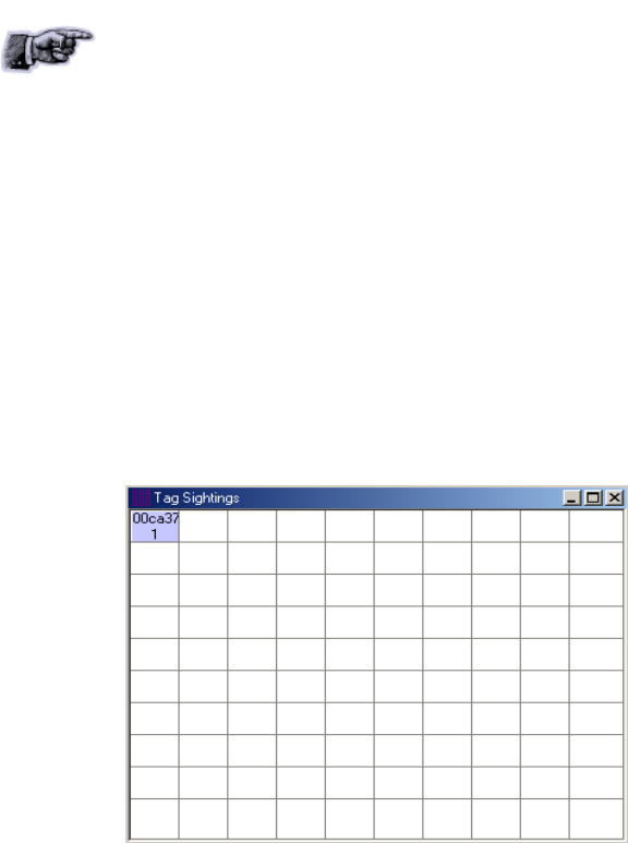
The first square in the grid should turn from white to blue and display the
tag’s ID number and the number of times the tag was sighted (should be
one). An example of this is shown below.
MARS-1-2-4-6 USER MANUAL 64-70-017-DOC ver.1
35

5. Reporting a Problem
If you are having a problem with a Magellan Reader, you will need to send a
report to your support organisation. To make the diagnosis quicker and
easier, please supply your problem report on a Service Form along with the
following information:
What kind of tags are you
using and how many are
you putting on the
Reader at one time?
Have this Reader and the
tags you are using
worked at any time in
the past?
Have you tried connecting
to the Reader with a
different PC?
Have you successfully
installed the
ReaderManager
application?
In the ReaderManager,
select the Help/About
ReaderManager menu
item and record on the
Service Form what
version numbers are
shown in the window
that appears.
The required information about Model Number, S/N, P/N and D/C is located
on OEM label on the back of the equipment.
Warranty Repairs
Before shipping any Reader a Return Authorisation number (RMA) must be
obtained.
End-users should contact the company from
whom they purchased the Reader for repair,
replacement or refund.
If you purchased the Reader directly from
Magellan, contact Magellan for a Return
Authorization number (RMA) before shipment.
The copy of the Service Form with RMA must be enclosed in the original or
equivalent packing with the RMA number clearly marked on the outside of
the box.
Non-Warranty Repairs
MARS-1-2-4-6 USER MANUAL 64-70-017-DOC ver.1
36
If a Reader needs repairing after one year warranty period expires, your
support organization or Magellan if you purchased directly from Magellan
will first provide an estimate of repair charges. Then upon receiving
approval from you the Reader can be sent for repair. Refer to above
Warranty Repairs information for return procedures.
MARS-1-2-4-6 USER MANUAL 64-70-017-DOC ver.1
37
5.1Troubleshooting
Problem Reason Solution
LEDs
Red LED is off Power cable not
connected
Ensure the power cable is connected correctly to both
the mains power and to the Reader
Power cable faulty Replace the cable
Power adaptor faulty Replace the power adaptor
Reader faulty Send a service report on the Service Form
Absence of the flashing
green LED during tag
reading
Incorrectly oriented
tag/tags
Ensure tag/tags are oriented correctly to the Reader
Antenna (see Tag-to-Reader/Tag-to-Antenna
Orientation).
Faulty tag/tags Replace tag/tags. Do not use tags with a black dot or
black square marking (faulty tags).
The Powering Field is off Ensure the powering field is on. Go to Tools>
System>Reader Setting. Tick the Powering Field box.
Reader faulty Send a service report on the Service Form.
Green LED flashes but I
can not see any tag
message in the
ReaderManager
USB or Ethernet
connection is not
functioning
Ensure the communication cable is connected
correctly.
The reader is not
Connected
Ensure the Reader is turned on and a communication
cable is plugged in. The status bar in bottom right
corner of the ReaderManager window has to show an
indication Connected, the tag type and the IP address.
The tag type is
incompatible with the
Reader
Use the appropriate tag type according to the chart in
the Reader-Tag Compatibility section.
A communication tool
has not been chosen
Choose Grid of tag sight counts or Table of Tag
Messages from Tools->System menu to view tag
replies.
Antenna installation
and maintenance
Antenna test failed Wrong tag. The tag used
for the test is in a low
power mode.
Make sure you use a normal/fully powered tag for
testing (refer to the Working with Tags section in the
Reader User Manual). Perform the test again.
Faulty tag Replace tag. Do not use a tag with a black dot or black
square marking (faulty tag).
Antenna is not on the list
of available antenna
types
You have purchased
new antenna type which
is not in your version of
the ReaderManager
Download the latest version of the ReaderManager
available from Magellan’s website. Then upgrade the
ReaderServer on your Reader using the
ReaderManager.
Antenna does not work
as good as before
(reduced read range,
etc.)
The Antenna has been
moved recently and was
not tuned
Once you change the antenna position, moved the
antenna or replaced the mounting material you should
understand first whether the antenna is affected by the
mounting material, put a plastic spacer if affected and
tuned the antenna again.
Metallic object/s,
electronic devices or
cables are in the close
vicinity of the antenna
and affect the antenna
performance
Move all metallic objects, electronic devices and cables
away from the antenna or shield the antenna by a
purpose built ferrite shield. Once you do so the antenna
should perform as before. Measure the maximum
voltage, compare with the voltage previously recorded
and tuned the antenna if it’s required.
Connecting a Reader
Can not find and connect
to the Reader as the
Reader is not shown on
the Connection menu list
The Reader was not in
the operational mode
when you connected a
communication cable
and/or opened the
Connection menu
Plug in the communication and power cables. Wait for
about 1 minute after you apply the power to the
Reader. The blue LED must to be permanently lit and
the green LEDs off. In the ReaderManager open the
Connection menu. Find the Reader you want to
connect to on the list.
MARS-1-2-4-6 USER MANUAL 64-70-017-DOC ver.1
38

The PC does not
recognise the Reader at
all
The USB port on the
PC is broken
Use another USB port known to be working.
USB port has
temporarily failed
Power cycle the PC.
The Reader is faulty Check the Reader on two other PCs. If no PC shows
any response at all to the USB cable being plugged in
then it’s faulty. Send a service report on the Service
Form.
USB cable faulty Change the USB cable.
The PC recognises the
Reader, but claims that it
is faulty in the Windows’
Device Manager and
does not create a
network connection
Windows has previously
marked the Reader as
faulty and will not try to
connect to it or load the
Reader driver. Usually
caused by rapidly
unplugging and plugging
of the USB cable.
Make sure that the USB cable is unplugged and the
Reader is turned off. Remove/Unistall the faulty device
from the Device Manager, then plug the USB in, turn
the Reader on and wait for a network connection again.
Alternatively you can connect a different Reader to the
PC as it will have a different serial number and
Windows will not flag it as faulty.
The Reader is connected,
and appears to be
working correctly but the
network connection drops
out after a few seconds
A Reader was replugged
too quickly before
Windows finished
processing the previous
network connection
Wait at least 30 seconds before replugging any Reader
into the same PC or wait until the network connection
disappears.
USB hub does not work
properly
Power cycle the PC. Try a rear USB port on PC to plug
a USB cable. Avoid using an external USB hub.
No network connection
can be made to a Reader
but the Network
Connections window
shows that the Reader is
connected and all other
network status
information indicates that
networking should be
working
The USB port on the PC
has stopped working for
an unknown reason.
Use another USB port. If this fails, power cycle the PC.
MARS-1-2-4-6 USER MANUAL 64-70-017-DOC ver.1
39

5.2Service Form
Always return a copy of this
form along with the product
CONTACT
Company _____________________________
Address ______________________________
Country ______________________________
Sales Order ___________________________
PO Number ___________________________
Purchase Date _________________________
Return Authorisation number (RMA) ______________
Date ________________________________________
Technical Contact _____________________________
Telephone ___________________________________
Fax _________________________________________
Email _______________________________________
PRODUCT
From OEM label on the back of the equipment:
Model __________________________
P/N ___________________________________
D/C ___________________________________
S/N ___________________________________
MLC __________________________________
(first number in order after black dots)
Describe any hardware modifications made to the unit and modification date:
______________________________________________________________________________________________________
______________________________________________________________________________________________________
______________________________________________________________________________________________________
______________________________________________________________________________________________________
______________________________________________________________________________________________________
______________________________________________________________________________________________________
REASON FOR RETURN
Describe problems (see Reporting a Problem):
______________________________________________________________________________________________________
______________________________________________________________________________________________________
______________________________________________________________________________________________________
______________________________________________________________________________________________________
______________________________________________________________________________________________________
______________________________________________________________________________________________________
______________________________________________________________________________________________________
______________________________________________________________________________________________________
______________________________________________________________________________________________________
______________________________________________________________________________________________________
______________________________________________________________________________________________________
______________________________________________________________________________________________________
______________________________________________________________________________________________________
______________________________________________________________________________________________________
______________________________________________________________________________________________________
______________________________________________________________________________________________________
RETURN TO*
If purchased from Magellan:
Magellan Technology Pty Limited
65 Johnston St.
Annandale
NSW 2038
Australia
Tel.: +61 2 9562 9800
Fax: +61 2 9518 7620
Email: info@magtech.com.au
Website: www.magtech.com.au
* End-users should contact the company from whom they purchased the Reader
MARS-1-2-4-6 USER MANUAL 64-70-017-DOC ver.1
40


7.Revision History
Version Date Person Reason
Ver.1 09.2006 Olga Kolesnik Initial User’s Guide (40-01-005-DOC) has been split into
separate User Manuals for each reader. New user-friendly
document layout/design, new logo, new sections added
(Alert Symbols, Glossary, Product Overview, Service
Form, Specifications, Revision History)
MARS-1-2-4-6 USER MANUAL 64-70-017-DOC ver.1
42

8.Appendix
8.1Specification
MARS-1-2-4-6
Multiple Antenna Reader Systems
Read and write operations
No user-serviceable parts
ISO/IEC Compliance 18000-3 Mode 2
Operating Frequency 13.56 MHz
Number of Reply Channels 2
Command Data Rate 424 kbit/s
Reply Data Rate 106 kbit/s per channel
Tag Type PJM StackTag® and PJM ItemTag®
External Dimensions (L x W x H): 300 x 213 x 46 mm with fixed mounting
brackets
Net Weight 3 kg (without external antennas)
Low Voltage Input 12 VDC @ 1.5 A
Operation environment Indoor use
Temperature range +10oC to +45oC
Humidity 10% to 80% (non-condensing)
Recommended Minimum Host Computer
Requirement Windows XP SP2/ 500 MHz CPU/ 128MB RAM
Host Interface USB and Ethernet
Number of External Antennas:
MARS-1 1
MARS-2 Up to 2
MARS-4 Up to 4
MARS-6 Up to 6
External Antennas
Single-axis antennas with inner coil
dimensions:
(custom design is available on request)
Round 60 mm diam. X 0.8 mm and 124 mm
diam. X 0.8 mm
Rectangular 60 x 420 x 0.8 mm, 120 x 240 x
0.8 mm, 202 x 352 x 0.8 mm and 202 x 353
x 3.2 mm
Antenna RCA Connection Cable Length 1.5 m
MARS-1-2-4-6 USER MANUAL 64-70-017-DOC ver.1
43
8.2External Antenna Types
These devices have been assigned to operate with the antennas listed
below, and having maximum gain of 3.5 dB. Antennas not included in this
list or having a gain greater than 3.5 dB are strictly prohibited for use with
these devices. The required antenna impedance is 4 ohms.
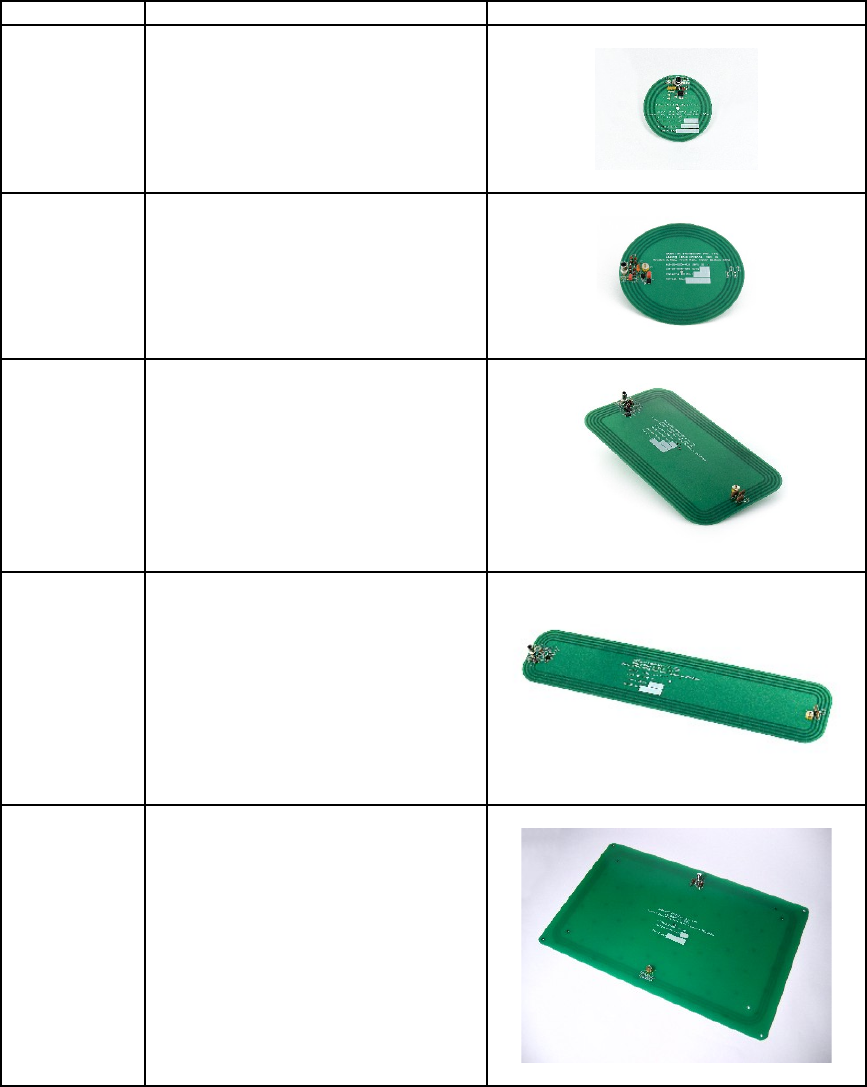
Part Number Description Photo
61-10-002 Round,
30 mm inner antenna coil radius,
thickness 0.8 mm,
single axis
63-10-005 Round,
60 mm inner antenna coil radius,
thickness 0.8 mm,
single axis
63-10-004 Rectangular,
inner antenna coil dimensions
120x240 mm,
thickness 0.8 mm,
single axis
63-10-003 Rectangular,
inner antenna coil dimensions
60x420 mm,
thickness 0.8 mm,
single axis
64-10-002 Rectangular,
inner antenna coil dimensions
202x352 mm,
thickness 3.2 mm,
single axis
MARS-1-2-4-6 USER MANUAL 64-70-017-DOC ver.1
44
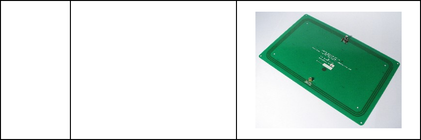
64-10-004 Rectangular,
inner antenna coil dimensions
202x352 mm,
thickness 0.8 mm,
single axis
MARS-1-2-4-6 USER MANUAL 64-70-017-DOC ver.1
45

8.3Reader-Tag Compatibility
Maximum Read-Write
Distance* (MRD), mm
READER-WRITERS
MPR- 5050
MARS and
round external
antenna
(60 mm radius)
MSTRP-
5050
MDOCR-
2505
MDR-
1109
MTR-
1310
S
T
A
C
K
T
A
G
S
Rectangular,
76 x 45 mm, 5 turns 315 235 60
Rectangular,
76 x 45 mm, 2.5 turns 160 170 30
Rectangular, 56 x 26 mm 280 220 55
Round, 35 mm diameter 145 170 40
Round, 25 mm diameter 115 15
Round, 20 mm diameter 100 10
Rectangular, 28 x 16 mm 120 15
Rectangular, 20 x 15 mm 95 10
I
T
E
M
T
A
G
S
Rectangular,
76 x 45 mm, 5 turns 540 370 110
Rectangular, 20 x 15 mm 135 25
* - Measured for a single tag
- Tags operate inside an internal volume or shrouded area
MARS-1-2-4-6 USER MANUAL 64-70-017-DOC ver.1
46
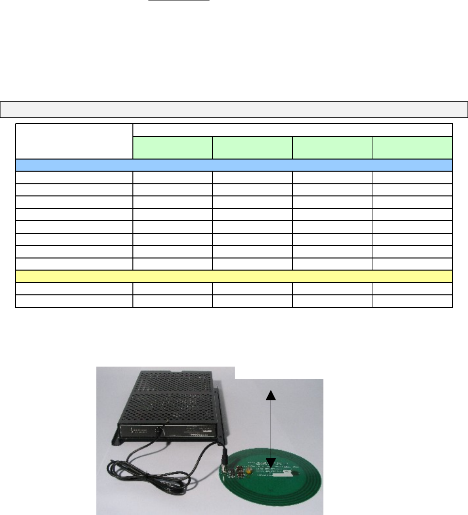
8.4Maximum Read-Write Distance
Maximum Read-Write Distance: MARS with External Antennas
Maximum Read-Write
Distance* (MRD), mm
External antenna type
60 mm radius 120x240 mm 60x420 mm 202x352 mm
StackTag tags
20x15 mm 95 95 60 65
28x16 mm 120 125 75 110
20 mm diameter 100 100 60 70
25 mm diameter 115 120 75 110
35 mm diameter 170 195 130 205
56x26 mm 220 250 185 280
76x45 mm, 2.5 turns 170 195 130 205
76x45 mm, 5 turns 235 270 200 300
ItemTag tags
20x15 mm 135 140 95 155
76x45 mm, 5 turns 370 440 350 505
* - Measured with a single tag
MARS-1-2-4-6 USER MANUAL 64-70-017-DOC ver.1
MRD ± 5 mm
47