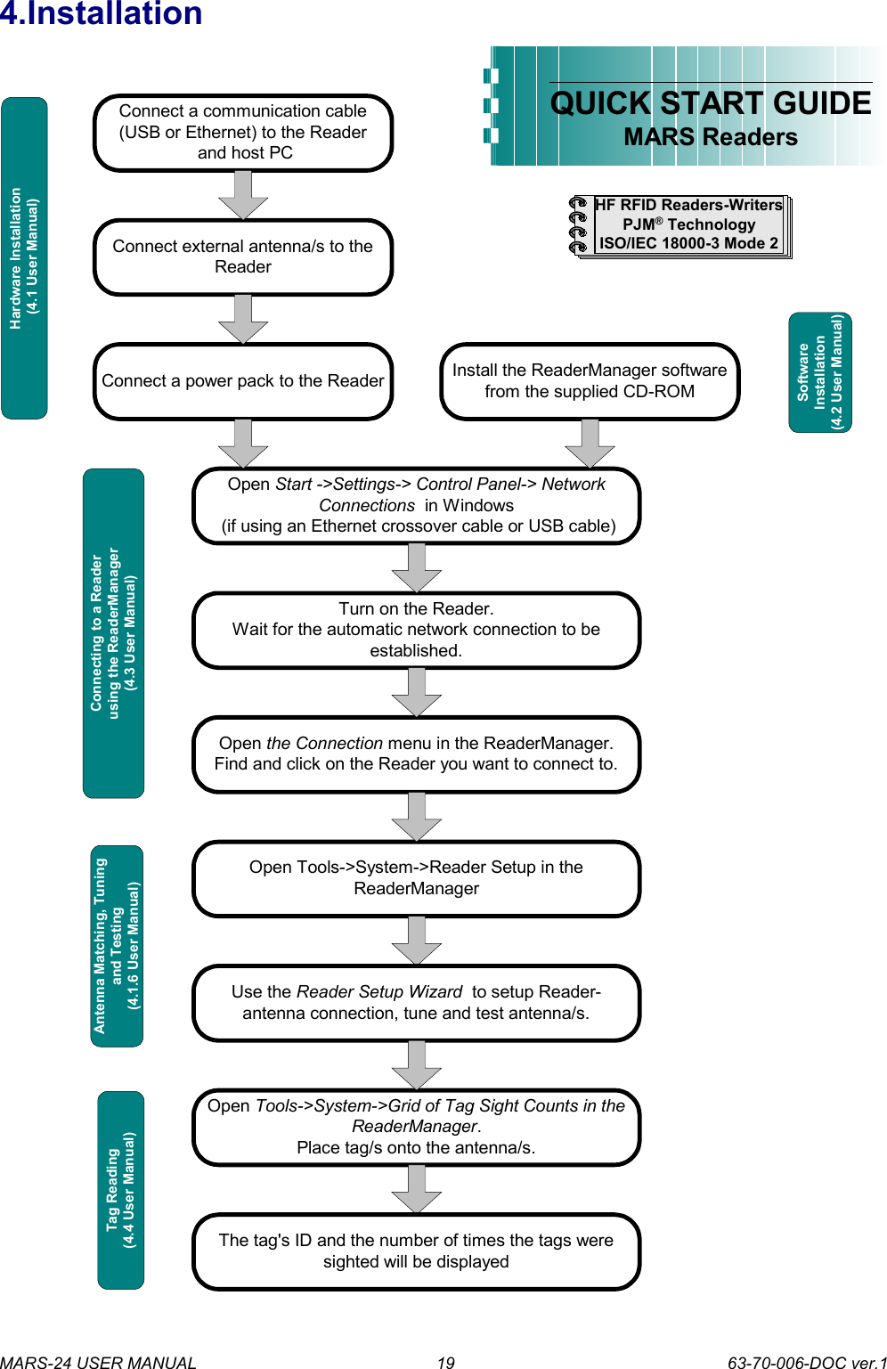
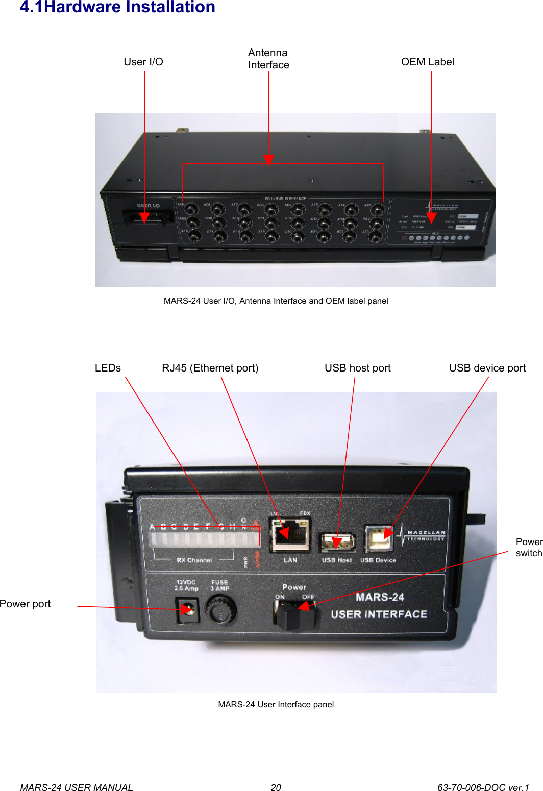
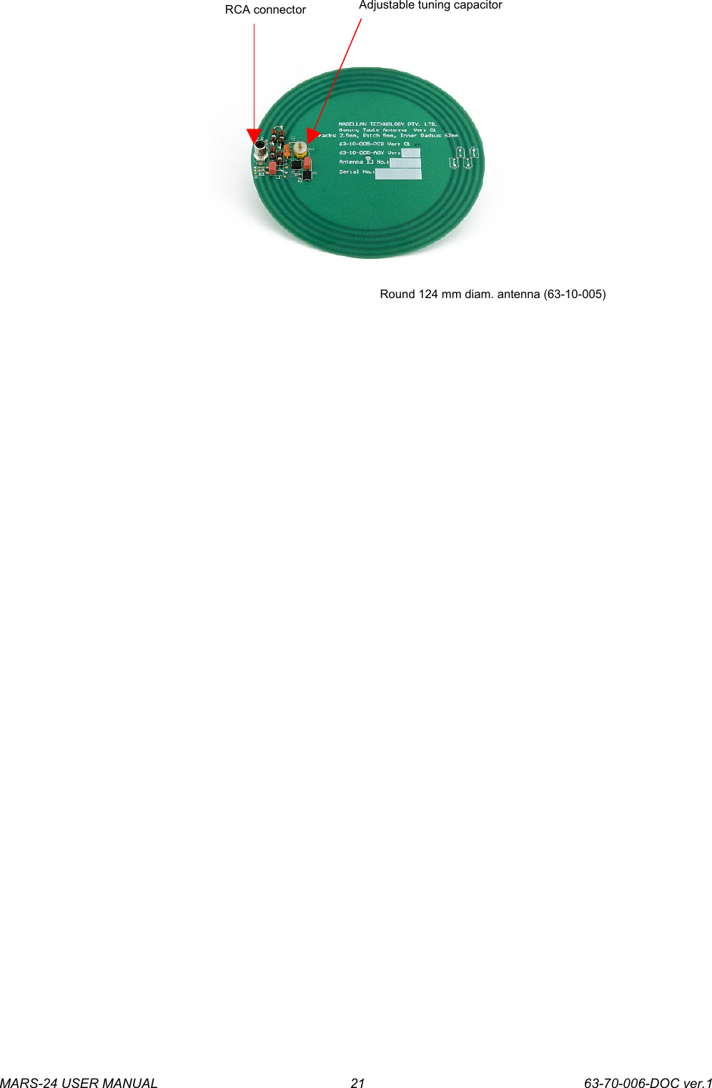
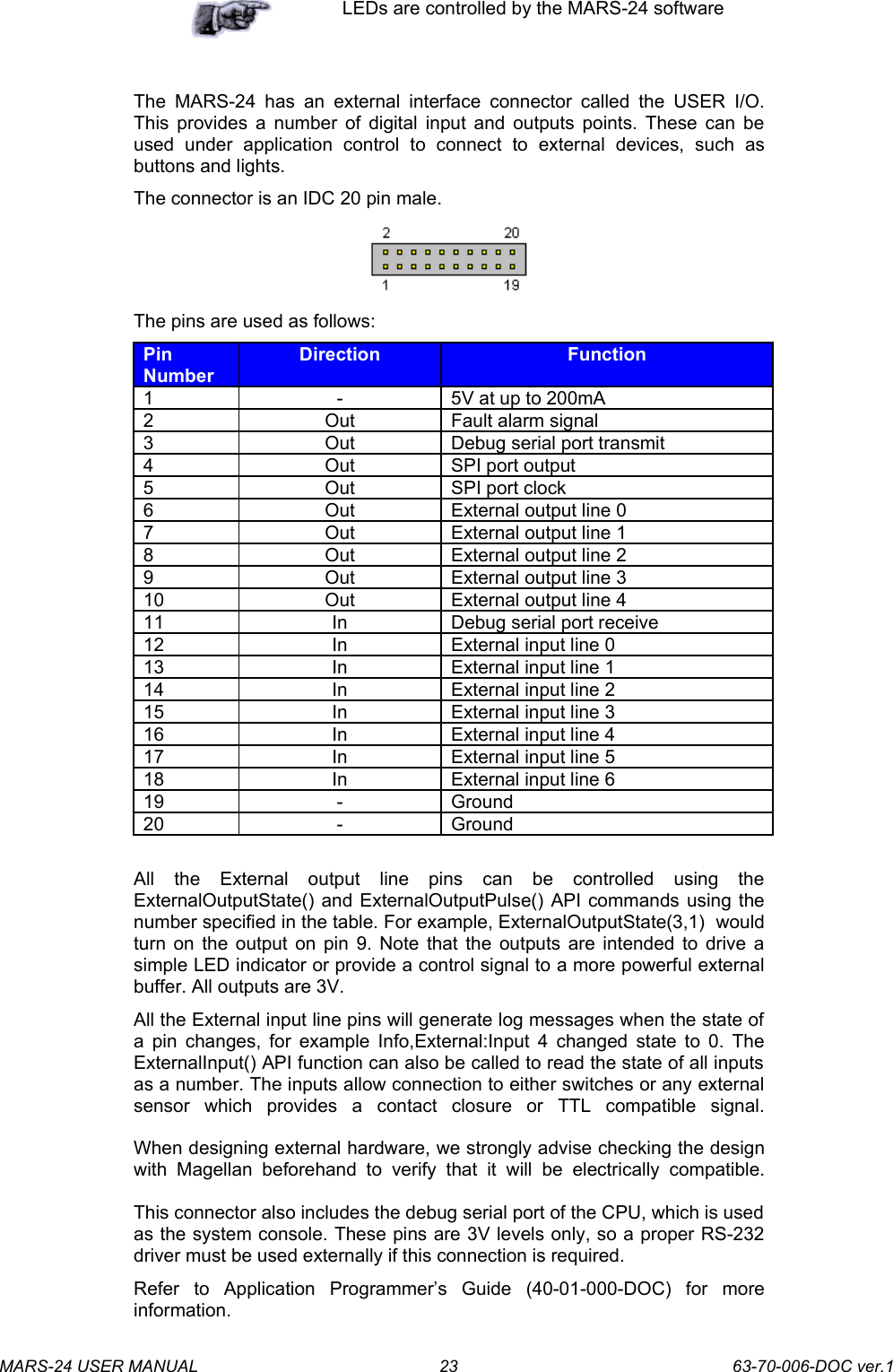
Sato Vicinity MARS-24 MARS-24 Desktop Reader User Manual APPENDIX L

Sato Vicinity Pty Ltd MARS-24 Desktop Reader APPENDIX L

users manual

 Page 1 of 116   EMC Technologies Pty LtdABN 82 057 105 549 Unit 3/87 Station Road Seven Hills NSW 2147 Australia  Telephone      +61 2 9624 2777 Facsimile       +61 2 9838 4050 Email         syd@emctech.com.au www.emctech.com.au  Melbourne 57 Assembly Drive Tullamarine Vic 3043 Tel:   +61 3 9335 3333 Fax:  +61 3 9338 9260 Sydney Unit 3/87 Station Road Seven Hills NSW 2147 Tel:   +61 2 9624 2777 Fax:  +61 2 9838 4050 Brisbane 1/15 Success Street Acacia Ridge Qld 4110 Tel:   +61 7 3875 2455 Fax:  +61 7 3875 2466 Auckland (NZ) 47 MacKelvie Street Grey Lynn Auckland Tel:   +64 9 360 0862 Fax:  +64 9 360 0861        APPENDIX L OF TEST REPORT T61218_F   USER MANUAL AND READER MANAGER GUIDE     FCC ID:  TVN-MARS-24 Manufacturer:  Magellan Technology Test Sample:  RFID Terminal Model:   MARS24 Serial Number:  Production Prototype    Date:  15th January 2007
 HF RFID System User Manual MARS-24 Multiple Antenna Reader-Writer System - 24Document Number : 63-70-006-DOC ver.1Last Changed : 16 January 2007Copyright  Magellan Technology 2007Commercial in Confidence
Content1. INTRODUCTION                                                                                                                                                               -------------------------------------------------------------------------------------------------------------------   2  1.1 REGULATION AND STANDARDS                                                                                                                                               ..........................................................................................................................................   2  1.2 WARRANTY                                                                                                                                                                         ...................................................................................................................................................................   3  1.3 LIMITATION OF LIABILITY                                                                                                                                                      .................................................................................................................................................   3  1.4 CHANGES IN PRODUCT FAMILY, SPECIFICATIONS AND USER MANUALS/GUIDES                                                                            .......................................................................   3  1.5 COPYRIGHTS AND COPY PERMISSION                                                                                                                                       ..................................................................................................................................   3  1.6 MEANING OF ALERT SYMBOLS AND SIGNAL WORDS                                                                                                                ...........................................................................................................   3  1.7 GLOSSARY OF TERMS AND ABBREVIATIONS                                                                                                                             ........................................................................................................................   5  2. PRODUCT OVERVIEW                                                                                                                                                    ----------------------------------------------------------------------------------------------------------   7  2.1 MARS-24                                                                                                                                                                         ....................................................................................................................................................................   7  3. BEFORE YOU BEGIN                                                                                                                                                       ------------------------------------------------------------------------------------------------------------   8  3.1 UNPACKING AND INSPECTION                                                                                                                                                 ............................................................................................................................................   8  3.2 INSTALLATION ENVIRONMENT                                                                                                                                              .........................................................................................................................................   10  3.3 RECOMMENDED SYSTEM REQUIREMENTS                                                                                                                               ..........................................................................................................................   10  3.4 INSTALLATION REQUIREMENTS                                                                                                                                             ........................................................................................................................................   11  3.5 ANTENNA MAINTENANCE (TUNING)                                                                                                                                     ................................................................................................................................   14  3.6 WORKING WITH TAGS                                                                                                                                                         ...................................................................................................................................................   16  3.7 TAG-TO-ANTENNA ORIENTATION                                                                                                                                         ....................................................................................................................................   18  4. INSTALLATION                                                                                                                                                              ------------------------------------------------------------------------------------------------------------------   19  4.1 HARDWARE INSTALLATION                                                                                                                                                  .............................................................................................................................................   20  4.1.1 Connecting to a power supply                                                                                                                                ...........................................................................................................................   22  4.1.2 Connecting a Reader to a Computer using USB                                                                                                    ...............................................................................................   24  4.1.3 Connecting a Reader to a Computer using Ethernet                                                                                             ........................................................................................   24  4.1.4 Connecting Multiple Readers to a local network                                                                                                   ..............................................................................................   25  4.1.5 Connecting External Antennas                                                                                                                               ..........................................................................................................................   25  4.1.6 Antenna Matching, Tuning and Testing                                                                                                                 ............................................................................................................   26  4.2 READERMANAGER SOFTWARE INSTALLATION                                                                                                                         ....................................................................................................................   27  4.2.1 Installation and Functionality Test                                                                                                                        ...................................................................................................................   27  4.2.2 Upgrading software                                                                                                                                                ...........................................................................................................................................   28  4.3 CONNECTING TO A READER USING READERMANAGER                                                                                                             ........................................................................................................   29  4.3.1 Getting an IP address using Ethernet                                                                                                                    ...............................................................................................................   31  4.3.2 Getting an IP address using USB                                                                                                                           ......................................................................................................................   33  4.3.3 Getting a Reader connected using the ReaderManager                                                                                        ...................................................................................   35  4.4 COMMUNICATION TEST                                                                                                                                                       ..................................................................................................................................................   37  5. REPORTING A PROBLEM                                                                                                                                            ----------------------------------------------------------------------------------------------------   38  5.1 TROUBLESHOOTING                                                                                                                                                             ........................................................................................................................................................   40  5.2 SERVICE FORM                                                                                                                                                                  .............................................................................................................................................................   42  6. CONTACT US                                                                                                                                                                   ----------------------------------------------------------------------------------------------------------------------   43  7. REVISION HISTORY                                                                                                                                                      ------------------------------------------------------------------------------------------------------------   44  8. APPENDIX                                                                                                                                                                        --------------------------------------------------------------------------------------------------------------------------   45  8.1 SPECIFICATION                                                                                                                                                                   ..............................................................................................................................................................   45  8.2 EXTERNAL ANTENNA TYPES                                                                                                                                                ...........................................................................................................................................   46  8.3 READER-TAG COMPATIBILITY                                                                                                                                              .........................................................................................................................................   48  8.4 MAXIMUM READ-WRITE DISTANCE                                                                                                                                     ................................................................................................................................   49
   Please read before proceedingPlease   read   and   understand   this   document   before using Magellan’s Readers.If you have any questions, comments or suggestions about the User Manual please contact Magellan Technology.  Important InformationInstallation EnvironmentFor indoor use only unless otherwise specified. Install Magellan’s Readers within the temperature and humidity range according to the product specification.The environment must not contain corrosive, flammable or explosive agents or be subject to rapid changes in temperature, to direct vibration or shock.InstallationMagellan’s RFID reader-writers communicate with data carriers (RFID inlets, labels and tags) using the 13.56  MHz  High Frequency  (HF)  band. Some  industrial machines and  electronic devices can  generate  unwanted  noise   which may   degrade  communication. Make  sure that other equipment is properly installed, grounded and at a reasonable distance from the Reader and/or Reader antennas.Wireless  communication  can be degraded  by high-voltage  and  high-current lines and other sources of strong electric and magnetic fields. Installation in such locations should be avoided.!Magellan’s RFID reader-writers are to be professionally installed by authorised, qualified and service-trained installation personnel only.MaintenanceAll   Magellan’s   RFID readers-writers   are   low   maintenance   equipment.   Except   for   externally accessible fuses there are no user-serviceable parts in any Reader. There is no requirement to remove the cover of the Reader.!Removal of the Reader cover by unauthorised personnel will void the product warranty.Do not attempt to clean internally. Periodic cleaning of external case parts with a damp cloth is advisable. Turn off the Reader before cleaning. Do not use a solvent of any kind.Electrical SafetyIn order to avoid electric shock do not remove the Reader cover or   attempt   to   repair.   The   Reader   must   be   maintained   by authorised, qualified and service-trained personnel only. EnvironmentalFor disposal readers should be treated as industrial waste.This symbol on the product or on its packaging indicates that this product shall not be treated as household waste. Instead it shall be handed over to an appropriate collection point for the recycling   of   electrical   and   electronic   equipment.   By   ensuring   this   product   is   disposed   of correctly,   you   will   help   prevent   potential   negative   consequences   for   the   environment   and human   health,  which   could   otherwise   be   caused   by   inappropriate   waste   handling   of   this product. The recycling of materials will help to conserve natural resources. For more detailed information about recycling of this product, please contact your local city office, your household waste disposal service or the Magellan Technology regional sales office.MARS-24 USER MANUAL              63-70-006-DOC ver.11
1.IntroductionThank you for your recent purchase of a Magellan RFID reader-writer.This   User   Manual   will   provide   you   with   information   to   rapidly   adopt Magellan’s PJM technology for your needs, to install the Reader hardware and ReaderManager software and get the Reader running.Refer to the ReaderManager Guide (40-01-006-DOC) for a description of the  various  tools   and  advanced  options  available  in   the  ReaderManager software.Programming is covered in the Application Programmer’s Guide (40-01-000-DOC).1.1Regulation and StandardsRFID equipment is subject to national and international regulations.FCC Radio Frequency Interference Statement (USA)The FCC regards RFID equipment as low-power transmitting devices and, therefore, does  not require  users of RFID devices to obtain a  license to operate them.NOTE: This equipment has been tested and found to comply with the limits for a Class B digital device, pursuant to Part 15 of the FCC Rules. These limits   are   designed   to   provide   reasonable   protection   against   harmful interference  in  a  residential  installation.  This  equipment  generates,  uses, and can radiate  radio frequency energy and, if not  installed and used in accordance with the instruction manual, may cause harmful interference to radio communications. However, there is no guarantee that interference will not occur in a particular installation. If this equipment does cause harmful interference to radio or television reception, which can be determined  by turning the equipment off and on, the user is encouraged to try to correct the interference by one or more of the following measures:Reorient or relocate of receiving antennaIncrease the separation between the equipment and receiverConnect the equipment into an outlet on a circuit different from that to which the receiver is connectedConsult the dealer or an experienced radio/TV technician for help!Any  changes or  modifications to   the  equipment that  are not expressly  approved  by   the  party   responsible  for   compliance could  void  the   user’s  authority   granted  under  FCC  Rules  to operate this equipment.       FCC ID: TVN-MARS-24Industry Canada Radio Frequency Interference Declaration of Conformity (Canada)This Class A digital apparatus complies with Canadian ICES-003.Cet appareil numérique de la classe A est conforme à la norme NMB-003 du Canada.ICES\NMB-003 IC: 6596A-MARS24MARS-24 USER MANUAL              63-70-006-DOC ver.12
Other RegulationsEUETSI EN 300 330-1 v.1.3.1 (2001-06)ETSI EN 300 330-2 v.1.2.1 (2004-11)ETSI EN 489-1 v.1.5.1 (2004-11)ETSI EN 489-3 v.1.4.1 (2002-08)EN 61000-3.2: 2002EN 61000-3.3: 1995Safety: IEC/EN 60950PendingAS/NZS CISPR 22: 20044268: 2003 PendingISO/IEC 18000 – 3 Mode 2 (Air Interface at 13.56 MHz) ComplianceMagellan’s Readers fully complies with the ISO/IEC 18000 Part 3 Mode 2 (Information   technology   –   Radio   frequency   identification   for   item management. Part 3: Parameters for air interface communications at 13.56 MHz) published in August, 2004.1.2WarrantyMagellan’s warranty and liability with respect to products and/or services is for   a   period   of   12   months   from   date   of   delivery   and   is   limited   to   the rectification of faulty workmanship and/or non-compliance by Magellan.Any liability with respect to components including purchased or free issued items and other materials used in the manufacture of products are covered by, and limited to, any warranty provided by the original manufacturer. 1.3Limitation of LiabilityMagellan’s warranty excludes products that have been improperly installed or maintained, modified or misused. Notification of claims must occur within the warranty period.End-users   should   contact   the   company   from   whom   they   purchase   the products for replacement, repair or refund.If   purchases   the   Reader   directly   from   Magellan,   contact  Magellan   for   a Return Authorization Number (RAN) before shipment.1.4Changes in Product Family, Specifications and User Manuals/GuidesThis document is subject to change without notice in future editions. Magellan  reserves the  rights  to  change  its product  design,  specifications and product range. 1.5Copyrights and Copy PermissionThis document shall not be copied, reproduced or transmitted in any form or by  any   means  without  written  permission  from   Magellan  Technology  Pty Limited. This document is protected by copyrights and is intended solely for use in conjunctions with Magellan’s products only. 1.6Meaning of Alert Symbols and Signal WordsNotes and Tips. Application Notes. MARS-24 USER MANUAL              63-70-006-DOC ver.13
!This part of the Manual requires your attention.!  CAUTIONIndicates a potentially hazardous situation which, if   not   avoided,   will   result  in   minor   or   moderate injury. Can cause property damage.!  WARNINGIndicates a potentially hazardous situation which, if   not   avoided,   will   result  in   minor   or   moderate injury,   or   may  result  in   serious   injury   or   death. Can cause significant property damage.Warning!In   order   to   avoid   electric   shock   follow   the instructions provided.MARS-24 USER MANUAL              63-70-006-DOC ver.14
1.7Glossary of Terms and AbbreviationsAntenna A  Reader antenna that emits  radio waves and receives   reply   signals   from   tags.   The   Reader antenna can be internal which is integrated into the Reader and external which is connected to the Reader via a cable. Antenna axis  The   antenna   port   on   the   Reader   antenna interface the antenna is plugged into.Antenna tuning Trimming   a   reader   antenna   to   its   highest possible field strength which corresponds to the highest operating voltage.Create axis group Create an antenna group. It means to combine antennas   or   antenna   ports   in   one   group   that serve the same purposes or applications.Configure axis group Configure group antenna behaviour. It means to set  up   all  antennas  in  the   group   to   the   same behavioural   parameters   which   will   be   default parameters for this group.D/C Date Code (month/year)DSB Digital Support BoardHDF High Density Fiberboard (for MARS only)HF High FrequencyGUI Graphical Use InterfaceIT ItemTag (chips, inlets and labels)ItemTag tags (IT tags) Magellan’s   labels   and   inlets   for   item   tagging (separated   items)   that   work   with   Magellan’s family of reader-writersLAN Local Area NetworkLED Light Emitting DiodeMDF Medium Density Fiberboard (for MARS only)MLC Machine   Level   Control   (System   Configuration Control)MRD Maximum Read-Write DistanceNetwork Connections windowIn   Windows   XP   open  Start->   Control   Panel-> Network  Connections  or  open  My   Computer-> Other   Places->   My   Network   Places->   View  Network ConnectionsOEM label Original Equipment Manufacture label is located on   the   back   of   the   equipment.  It   includes  the Model Number, P/N, D/C, S/N and MLC.PJM Phase Jitter Modulation or PJM™ is a registered Trade Mark of Magellan Technology Pty Limited.PJM   is   a   RFID   communication   technology developed   and   patented   by   Magellan Technology Pty Ltd and complies with ISO/IEC 18000-3   Mode   2.   PJM   technology   products include a range of RFID chips, inlets, tags and Readers. PJM ItemTag® Registered Trade Mark for Magellan’s ItemTag tagsPJM StackTag® Registered Trade Mark for Magellan’s StackTag tagsP/N Part NumberMARS-24 USER MANUAL              63-70-006-DOC ver.15
Power cycle the PC Shut up Windows and switch the PC off at the wall   and   wait  for  30   seconds   before   powering the PC back up again. For laptops this means removing the battery and waiting for 30 seconds. This ensures that the USB host controller chips on  the  motherboard  have  had a  chance  to  be fully reset.Power cycle the ReaderTurn  off  the  power  or  unplug  the  power  cable (the power port on  the Reader user  interface). Open   the  Network   Connections  window   in Windows.   Wait   for   the   Reader’   network connection   to   be   removed   from   the  Network Connections window. Plug the Reader back and wait for the network connection to re-appear and become Connected in the Network Connections window.   Connect   to   a   Reader   via   the ReaderManager’s Connection menu.Reader/s Magellan’s RFID reader-writer/sReaderManager Graphical   user   application   for   Windows/Linux which   provides   a   platform   for   testing, demonstrations and application developmentReaderServer Embedded   application   that   provides   the standard   Application   Programmer   Interface   to serve   end-user   applications.   This   application runs on the Reader.RFID Radio Frequency IDentificationRFID inlet A   RFID   device   comprising   a  microchip   and   a printed   antenna   (copper/aluminium/conductive inks) on a flexible substrate (PET plastic film)RFID label RFID inlet with adhesive backing (sticky label)RFID tag 1. generic name for RFID inlet and label;2. RFID   inlet   or   label   inserted   into   a housing   (glass,   polycarbonate, polyamid, epoxy, ABS, etc.)RFID reader-writer Device for reading and writing to RFID tagsRMA Return Authorisation numberSetup axis Setup antenna. To setup an antenna means to match   the   antenna   with   its   corresponding antenna port by choosing the antenna type from list in the ReaderManager.S/N Serial NumberST StackTag (chips, inlets and labels)StackTag tags(ST tags)Magellan’s   labels   and   inlets   for   item   tagging (stacked,   touched   or   overlapping   items)   that work with Magellan’s family of reader-writersMARS-24 USER MANUAL              63-70-006-DOC ver.16
2.Product OverviewIntended use of Magellan’s RFID Reader is to read and write information to individual Magellan ItemTags and multiple Magellan StackTags.The communication protocol used by the Reader is compliant with ISO/IEC 18000 - 3 Mode 2 (Air Interface at 13.56 MHz).2.1MARS-24Multiple Antenna Reader System – 24Multiple antenna system (up to 24 antennas) 8 reply channelsMARS-24 USER MANUAL              63-70-006-DOC ver.17
3.Before you begin3.1Unpacking and InspectionWhen you receive your system, inspect it for any obvious damage that may have occurred during shipment. If there is damage, notify the shipping carrier   and   the   supplier   of   the   equipment   or Magellan if purchase directly from Magellan.Until   you   have   checked   the   system,   save   the shipping   carton   and   packaging  materials   in   the event the unit has to be returned.The standard MARS-24 package includes the following components:Reader-writerExternal antennas (up to 24) and connection cables (up to 24)Power adaptorUSB data communication cable Quick Start Guide CD-ROMTest   tags   (required   for   Hardware   Functionality   Test   and Communication Test)Magellan Antenna Tuning Kit (optional)Power PackThe Reader connection to the power source is realized via a low voltage power pack (12VDC output).!A power cable is not included. End-users should purchase a power cable suitable for the country of use.!  CAUTION Only   power   cables   and   adaptors   that   are compliant  with  the   regulations  in   the  country  of use may be connected to Magellan’s equipment.Data Communication CablesMagellan supplies USB shielded cable (USB 2.0, 2 m long)!USB cable should not be longer than 3mMARS-24 USER MANUAL              63-70-006-DOC ver.18
!As shielded cables are generally required in order to comply with EMC emissions limits, the shielded cables recommended by   Magellan   Technology   must   be   used.   Unshielded   cabled may   be   used   where   explicitly   allowed   in   the   Installation Requirements section of this User Manual.Ethernet cable is not included with the supply.Magellan recommends CAT5 Ethernet cable.CD-ROMThe CD-ROM should contain the following files:AdbeRdrxx_enu_full.exe Self-extracting   installation   kit   for   the Adobe   Acrobat   reader,   which   is required to read and print PDF files.40-01-000-DOCApplication Programmer Guide.pdfPDF   document   describing   how   to program all of Magellan’s Readers.40-01-006-DOCReaderManager GuidePDF document describing various tools and   advanced   options   available   in ReaderManager software.63-70-006-DOCUser Manual.pdfPDF version of this document.ReaderManager-Install.exe Self-extracting installation kit for theReaderManager.Once you install the ReaderManager software the User   Manuals   and   Guides   can   be   open   in Windows:Start -> (All) Programs -> Magellan Technology -> User Manuals.MARS-24 USER MANUAL              63-70-006-DOC ver.19
3.2Installation EnvironmentMagellan’s Readers are designed to operate in indoor environments where temperature   and   humidity   are   controlled   unless   other   conditions   are specified for customised Readers.For standard Readers the temperature range is from +10oC to +45oC. The humidity range is from 10% to 80% (non-condensing humidity).Install the Readers within the temperature and humidity ranges according to the product specification.The environment must not contain corrosive, flammable or explosive agents and conductive dust or be subject to rapid changes in temperature, direct vibration or shock.!  WARNINGDo   not   operate   this   Reader   in   an   environment which contains flammable or explosives gases or fumes.Magellan’s RFID reader-writers communicate with data carriers (RFID inlets, labels and tags) using the 13.56 MHz High Frequency (HF) band. Some industrial  machines and  electronic devices   can  generate unwanted  noise which   may   degrade   communication.   Make   sure   that   other   equipment   is properly   installed,   grounded   and  are   at   a  reasonable   distance   from  the Reader and/or Reader antennas.Wireless communication can be degraded by high-voltage and high-current lines and other sources of strong electric and magnetic fields. Installation in such locations should be avoided.In order to avoid electric shock do not remove the Reader cover or attempt to repair. Magellan’s reader-writers are to be maintained by authorised, qualified and service-trained personnel only. !Removal of the Reader cover by unauthorised personnel will void the product warranty.3.3Recommended System RequirementsRecommended minimum host computer requirements:Operating System: Windows XP SP2Memory: 128MB RAMHard Drive: 20 GBCPU: Intel Celeron 500Interface: USB or EthernetMARS-24 USER MANUAL              63-70-006-DOC ver.110
3.4Installation RequirementsPower supply requirements:Mains input: 110 - 240 VAC @ 50/60 HzLow voltage input (MARS-24): 12 VDC @ 2 AMARS-24   requires   special   installation   and   tuning   of   external   antennas. Refer to the ReaderManager User Guide (40-01-006-DOC) for the antenna matching, tuning  and testing instructions using the  Reader Setup Wizard tool.MARS’ external antennas are suitable for applications where many reading points  are  required.   MARS-24  is  capable  of   operating  up  to   24  external antennas that can be embedded into desk tops or shelves.Once antennas are placed in the position they are to be used,  it is essential  that they are fixed  in place and tuned. The tuning  is to be done only once at installation. All antennas (except the small round antenna 30 mm radius) have an adjustable capacitor that allows for tuning. MaterialsThe affect of materials and antenna position on antenna operation may be determined as follows:Place an antenna on a Styrofoam block and tune for maximum voltage at the antenna center using an Antenna Tuning Probe, digital voltmeter and a trimming tool. Then place the antenna on/into the installation   position   and   measure   the   maximum voltage again. Compare the voltage values.A difference of 10% or less is acceptable. If the voltage reduces more than 10%, this indicates the material is  adversely affecting  the antenna. The user   should   determine   if   the   reduction   in operation is acceptable by measuring read range and   stacking   operation.   If   the   reduction   is   not acceptable the antenna may be relocated.Alternatively   use   of   a   plastic   spacer   of   5   mm between the mounting material and the antenna is recommended   where   the   mounting   material   is adversely affecting the antenna.Reader antenna performance may be affected by conductive and metallic materials in the immediate vicinity of the antenna.Metal, metallic or metallized objects placed next to the Reader antenna may change the characteristics of the antenna affecting the tuning operation and reducing the read range.It’s recommended that the antenna not to be placed closer than 35 cm to any metallic object that is of a similar or larger size to the antenna.Small metallic objects such as jewelry or coins put on the antenna will have almost no affect on the antenna performance. If metallic conveyor rollers are a part of an application it’s advised to replace them with plastic parts if possible or apply shielding techniques as required. MARS-24 USER MANUAL              63-70-006-DOC ver.111
The materials that antennas are mounted on/into should not be metallic or conductive.Materials such as wood, laminated MDF, HDF or plywood have a limited conductivity. If an antenna is mounted into these materials some drop in the read range is expected in comparison with the equipment specification.  Plastics are   the best  materials to  embed antenna into provided they are graphite/carbon free.Try to avoid using black plastics as they may be conductive   due   to   carbon/graphite   based colouring agents.Clear  glass  is  generally  not  conductive and can  be used  as  a  desk  top material. Smoked and tinted glass may  be conductive and any affect on antenna operation should be determined by measurement.DistanceAntennas mounted in  a  close  proximity  to each  other  may  interfere with each other’s operation.For   antennas   connected   to   the   same   MARS   Reader   the   safe   distance between the antenna edges is antenna size dependent and varies from 5 cm (radius 30 mm round antenna) to 15 cm (202x352 mm antenna). For antennas connected to two different MARS Readers the safe distance between the antenna edges is also antenna size dependent and varies from 30 cm (radius 30 mm round antenna) to 60 cm (202x352 mm antenna). Do not mount an antenna on a desktop surface if there is a MARS reader immediately   below   and   under   the   antenna.   The   distance   between   the antenna and the MARS reader should be no less than 20 cm. Use extended brackets to increase the distance if required. Alternatively the MARS can be screened from the antenna by a purpose built ferrite shield.!In general no electronic devices and power adaptors are to be placed within 20 cm of the antenna in any direction. Before   such   installations   are   attempted   Magellan   must   be consulted.CablesDo not run any cables under or near antenna. Maintain a minimum distance of 15 cm.!The cables that connect external antennas with the reader are provided   by   Magellan.   The   MARS   Readers   should   only operate with antenna cables supplied by Magellan.!Any  changes or  modifications to   the  equipment that  are not expressly  approved  by   the  party   responsible  for   compliance will void the product warranty.How to shield antennasMARS-24 USER MANUAL              63-70-006-DOC ver.112
Antennas may be shielded by a purpose built ferrite sheet only. In special circumstances devices such as keyboards and computers may be placed under antennas where a purpose built ferrite antenna shield (64-50-001) is provide to protect the antenna.A ferrite shield consists of a sheet of aluminium with ferrite tiles, minimum thickness 5 mm.Contact   Magellan   for   further   information   on   shielding   antennas   for   you specific application and the specification of the Ferrite Antenna Shield (64-50-001) when planning your installation.MARS-24 USER MANUAL              63-70-006-DOC ver.113
3.5Antenna Maintenance (Tuning)Antennas   may   require   periodic   re-tuning   and   testing.   Detuning   of   an antenna may occur if physical environment around the antenna is changed. For   example  when   large   metal   objects  are   located   near   the  antenna  or electronic devices or cables are placed in close proximity with the antenna. The severity of detuning is dependent upon the size of the metal object and can only be determined by measurement.Before tuning make sure that metal objects, electronic devices and cables are not closer that the recommended distances in any direction from the antenna.The purpose of the tuning procedure is to maintain an antenna at its correct operating point. Tuning the antenna means to trim it to its highest possible field strength which corresponds to the highest voltage as measured by a voltmeter with an Antenna Tuning Probe.Contact Magellan for further instructions for your specific application.Equipment and Software Required for Antenna Tuning and Testing1 x Antenna Tuning Probe with cable (Magellan Antenna Tuning Kit) 1 x RF Trimming Tool (Magellan Antenna Tuning Kit) Antenna Tuning Kit: Antenna Tuning Probe with a cable and RF Trimming Tool1 x Universal Digital Voltmeter (to measure DC voltages between 1 and 15 volts) ReaderManager software– V2.05 or better 1 x Tag (fully powered tag)Tuning Instructions1. Connect  the  Antenna  Tuning  Probe  terminals to  the voltage  and input terminals of the digital voltmeter.2. Set the voltmeter to measure a DC voltage range greater than 10 volts.3. Place the Antenna Tuning Probe in the center of the antenna.4. Using   an   RF   trimming   tool   adjust   the   tuning   capacitor   on   the antenna for maximum voltage as measured by the tuning probe.MARS-24 USER MANUAL              63-70-006-DOC ver.114
Quality Assurance/ Quality ControlIf   the   maximum   read   distance   is   important   for your   application   then   the   antennas   have   to   be protected/shielded   from   the   interference   with   a mounting   material   firstly   and   then   tuned   at maximum voltage.In   case   the   maximum   read   distance   is   not   an issue   the   antennas   can   work   properly   even   at lower voltage but at a reduced read range.Method 1To confirm optimum antenna operation measure  the maximum read-write distance. 1. Take a single tag and position it over the Reader antenna center. Do not hold the tag antenna coil or tag inner area with you fingers. Preferably hold the tag edges or use a non metallic carrier to hold the tag.2. Measure the maximum read distance in mm and compare with the value for the same antenna-tag type in the  Maximum Read-Write Distance chart. Refer to this User Manual, Appendix. 3. If the maximum read-write distance is less than the chart value re-tuning may be necessary. If the antenna is correctly tuned then the user   should   determine   if   the   reduction   in   read-write   distance   is acceptable.Method 2During an initial tuning procedure measure the maximum voltage using an Antenna  Tuning  Probe.   Record  the   voltage   value  for   every  antenna.  To confirm tuning at any time measure the maximum voltage using the Antenna Tuning Probe and compare with the recorded results. The voltage values should be identical otherwise the antenna has to be tuned.MARS-24 USER MANUAL              63-70-006-DOC ver.115
3.6Working with Tags Do not stack ItemTags on top of each other. Only StackTags can be stacked, overlapped or touch each other.Single-axis Readers are tag orientation sensitive. Refer   to   the   Tag-to-Reader/Tag-to-Antenna section of this document.Reading  and  writing   speeds  depend  on  reader-tag   communication   speeds,   the   number   of receiver   channels,   amount   of   information   to   be read   and/or   written   and   the   number   of   tags presented   at   a   time.   The   additional   number   of tags   and   information   to   be   read   and   especially written slows down the read-write communication speed.  Please consult Magellan or your support organisation   regarding   these   issues   for   your specific application.Be   aware   that   tags   and   Readers   can   be incompatible   with   each   other.     Larger   tags   can work   with   all   types   of   Readers.   Smaller   tags require higher field strengths and as a result they may not operate with some Readers or have to be closer to a Reader antenna to operate. Refer to the   Reader-Tag   Compatibility   section   of   this document.StackTag   tags  delivered  on   a   roll   are  always   fully   powered  (ST   normal power mode  or 6000 mode). Fully or normal powered tags are ON all the time and reply to each Reader command providing they are in the field of the Reader antenna.To   decrease   tag   clashing   and   increase   anti-collision   and  stackability  for some applications the tags can be reconfigured by end-users to a ¼ low power mode (ST ¼ normal power mode  or 2000 mode). This means that tags in the ¼ low power mode are muted ¾ of the time and do not to reply to the Reader commands instantly.Tags can be reconfigured individually (one by one) or on mass (many at once).Before   reconfiguring   tags   make   sure   the ReaderManager software has been installed and upgraded   to   the   latest   version,   the   Reader   is running   and   the   Reader   is  Connected  to   the ReaderManager software. How to reconfigure tags individually or on mass1. In the ReaderManager go to Tools -> System -> Console. Click with the right mouse button and tick Show Tag Replies.2. Then   go   to  Reader   Configuration  and   choose Config_Normal_Powered_Tag  or  Config_Quarter_Powered_Tag (for the ReaderManager version 2.12 or higher).3. Place a single tag or multiple tags into the reader antenna field.4. Take the tag/tags off the reader.5. Follow the step 3 to 4 for a new batch of tags. 6. Once completed go to Reader Configuration and click on Clear All.MARS-24 USER MANUAL              63-70-006-DOC ver.116
How to check a tag configuration mode1. In   the   ReaderManager   go   to  Tools   ->   System   ->   Interrogate Command.2. In Reply select Normal and click Send.3. Then go to Tools -> System -> Table of Tag Messages to see the tag configuration in the Config column. The messages of all the tags currently in the reader antenna field can be seen. 2000 means that the   tag   has   been   reconfigured   to  ST   ¼   normal   power   mode configuration. 6000 means that a tag is in ST normal power mode.MARS-24 USER MANUAL              63-70-006-DOC ver.117
3.7Tag-to-Antenna OrientationTags should always be presented face on to the external antenna surface. They may still work at some angle depending upon the distance between the tag and the external antenna.Correct orientationCorrect orientationIncorrect orientation (90o angle)MARS-24 USER MANUAL              63-70-006-DOC ver.118
4.InstallationConnect external antenna/s to theReaderInstall the ReaderManager softwarefrom the supplied CD-ROMConnect a power pack to the ReaderOpen Start ->Settings-> Control Panel-> NetworkConnections  in Windows (if using an Ethernet crossover cable or USB cable)Turn on the Reader.Wait for the automatic network connection to beestablished.Open the Connection menu in the ReaderManager.Find and click on the Reader you want to connect to.QUICK START GUIDEMARS ReadersOpen Tools->System->Reader Setup in theReaderManagerUse the Reader Setup Wizard  to setup Reader-antenna connection, tune and test antenna/s.HF RFID Readers-WritersPJM® TechnologyISO/IEC 18000-3 Mode 2Open Tools->System->Grid of Tag Sight Counts in theReaderManager.Place tag/s onto the antenna/s.Connect a communication cable(USB or Ethernet) to the Reader and host PCHardware Installation (4.1 User Manual)SoftwareInstallation(4.2 User Manual)Antenna Matching, Tuningand Testing(4.1.6 User Manual)Tag Reading(4.4 User Manual)Connecting to a Readerusing the ReaderManager(4.3 User Manual)The tag's ID and the number of times the tags weresighted will be displayedMARS-24 USER MANUAL              63-70-006-DOC ver.119
4.1Hardware Installation             MARS-24 User I/O, Antenna Interface and OEM label panelMARS-24 User Interface panelMARS-24 USER MANUAL              63-70-006-DOC ver.120RJ45 (Ethernet port)USB device portPower portUSB host portOEM LabelAntenna InterfaceUser I/OLEDsPower switch
Round 124 mm diam. antenna (63-10-005)MARS-24 USER MANUAL              63-70-006-DOC ver.121Adjustable tuning capacitorRCA connector
4.1.1Connecting to a power supplyStep 1.  Connect a low voltage power pack to the unit.The connection  to the   power source is  realized via  a low  voltage power pack. The power cable is not supplied with the Reader and recommended to be purchased in the country of use.Step 2. Plug the power supply into AC power mains. When  power is applied  to  a  MARS-24 Reader the  LEDs  on  the Reader should operate as follows:the blue LED and green LEDs will immediately come on; both LEDs will go off in about 1 minuteMARS-24 with the blue and green LEDs onthe  blue LED  will come on again in 1-3 seconds indicating that the unit is in an operational mode; the green LEDs will be off MARS-24 with the blue LED. The Reader is in an operational modeonce the unit is in an operational mode the blue LED will remain lit the  green LEDs  will flash every time a tag/tags is/are successfully readMARS-24 USER MANUAL              63-70-006-DOC ver.122
LEDs are controlled by the MARS-24 softwareThe  MARS-24 has  an external  interface  connector called  the  USER I/O. This provides a number of digital input and outputs points. These can be used   under   application   control   to   connect   to   external   devices,   such   as buttons and lights.The connector is an IDC 20 pin male. The pins are used as follows:Pin NumberDirection Function1 - 5V at up to 200mA2 Out Fault alarm signal3 Out Debug serial port transmit4 Out SPI port output5 Out SPI port clock6 Out External output line 07 Out External output line 18 Out External output line 29 Out External output line 310 Out External output line 411 In Debug serial port receive12 In External input line 013 In External input line 114 In External input line 215 In External input line 316 In External input line 417 In External input line 518 In External input line 619 - Ground20 - GroundAll   the   External   output   line   pins   can   be   controlled   using   the ExternalOutputState() and ExternalOutputPulse() API commands using the number specified in the table. For example, ExternalOutputState(3,1)  would turn on the output on pin 9. Note that the outputs are intended to drive a simple LED indicator or provide a control signal to a more powerful external buffer. All outputs are 3V.All the External input line pins will generate log messages when the state of a pin changes, for example Info,External:Input 4 changed state to 0. The ExternalInput() API function can also be called to read the state of all inputs as a number. The inputs allow connection to either switches or any external sensor   which   provides   a   contact   closure   or   TTL   compatible   signal.When designing external hardware, we strongly advise checking the design with   Magellan   beforehand   to   verify   that   it   will  be  electrically   compatible.This connector also includes the debug serial port of the CPU, which is used as the system console. These pins are 3V levels only, so a proper RS-232 driver must be used externally if this connection is required.Refer   to   Application   Programmer’s   Guide   (40-01-000-DOC)   for   more information.MARS-24 USER MANUAL              63-70-006-DOC ver.123
4.1.2Connecting a Reader to a Computer using USBConnect   the   MARS-24   Reader   to   a   host  computer   using   the   USB   data communication cable by plugging the USB cable into the MARS-24 USB device port and the host computer USB port.Only one Magellan Reader can be connected to the PC via USB at a time (limited by Windows).!When the USB connection is used only a screened USB cable should be used.MARS-24 with the USB communication cable and power cable4.1.3Connecting a Reader to a Computer using EthernetConnect   the   MARS-24   Reader   to   a   host   computer   using   a   cross   over Ethernet cable. Plug   the Ethernet cross  over cable into  the MARS RJ45 socket (Ethernet port) and the network interface port on the PC.!Always connect Ethernet cable before power is applied to the Reader. MARS-24 USER MANUAL              63-70-006-DOC ver.124
4.1.4Connecting Multiple Readers to a local networkMultiple Readers can be connected to a local network using an Ethernet hub/switch. Plug the Ethernet communication cable into the MARS’s RJ45 socket (Ethernet port) and Ethernet Hub.!Always connect Ethernet cable before power is applied to the Reader. MARS-24 with the Ethernet communication cable and power cable4.1.5Connecting External AntennasConnect   each   external   antenna   to   a   Reader’s   Antenna   Axis/port   via   a supplied connection cable.MARS-24 with the external 124 mm diam. antenna connectedMARS-24 USER MANUAL              63-70-006-DOC ver.125
4.1.6Antenna Matching, Tuning and TestingBefore you start tuning and testing the antennas it’s   required   to   install   the   ReaderManager software   and   connect   to   a   Reader   in   the ReaderManager’s Connection menu.Refer   to   the   ReaderManager   Guide   (40-01-006-DOC)   for   the   antenna matching, tuning and testing instructions using the  Wizard  tool in  Reader Setup.Follow   the   procedure,   making   sure   that   the Magellan   Antenna   Tuning   Probe   and   voltmeter are used to measure when the tuning is correct.The  design   of  the antenna  and the selection  of the correct cable length are critical factors in the reliability of a Reader. Each antenna has unique set up values associated with it that are used by the software to ensure the Reader and antenna are matched to each other.The most critical part of the setup of MARS-24 is telling the Reader what type of antenna is connected to each antenna axis (Setup Axis).This is done using the Reader Setup tool in the Reader Manager. It provides a fixed list of antennas with known set up values for that particular Reader.If an antenna is not listed in this table it cannot be used with that Reader. Unless correct set up values are measured by Magellan and recorded in the list of known antennas, the antenna will not operate properly.If you can not find your antenna on the list you have to  upgrade the  ReaderManger software to the latest version assuming that you purchased a new  antenna   type  recently   to  be  used  with  the Reader   purchased   some   time   before.   You   will also need to upgrade the ReaderServer on your Reader.Update   the   ReaderManager   from   our   website first.   Then   you   can   upgrade   the   ReaderServer using   new   version   of   the   ReaderManager installed.Note that different release versions (MLC number) of the same Reader may well   have   very   different  set   up  values,  because  of  circuit   changes.   The Reader   selection   system   accounts   for   this   and   automatically   manages loading the correct values for a given version of the Reader.MARS-24 USER MANUAL              63-70-006-DOC ver.126
4.2ReaderManager Software InstallationThe ReaderManager application software allows tag data to be viewed and programmed. The   ReaderManager   can   only   connect   to   one   Reader   at   a   time.   The Connections  menu   allows   the   user   to   connect   to   other   Readers   by disconnecting from the currently connected Reader and then establishing a connection to a new Reader.It is possible to run many ReaderManagers on the same computer at the same  time.  Simply  double  click  on  the  ReaderManager  icon  to  open  up multiple instances of the ReaderManager.Refer to the ReaderManager Guide (40-01-006-DOC) for various tools and advanced options available in the ReaderManager.4.2.1Installation and Functionality TestStep 1. Insert the CD supplied with the Reader into the CD-ROM.Step 2. Open Windows Explorer, double click on ReaderManager-Install.Step 3. Ensure all the items in Install dialog are ticked, and then click the Install button.If  Python   is  not   installed  on   your  computer,  the   installation  program   will prompt  you if  you  would   like  to install  Python.  Click  the  Yes  button and accept all the default options during installation.When  the  ReaderManager  and all  the required libraries  are installed the dialog box will be displayed. Ensure the dialog box shows Completed  and no problems are reported.There is an option to install only an Ethernet-over-USB driver. Tick only the PJM Reader USB driver (RNDIS Ethernet)  box in  Install  dialog and press Install.Step 4. Click the Close button to continue.If  the   ReaderManager  is  already  installed,  double  click  ReaderManager-Upgrade. Follow steps 3 to 4 above.If Python and PyQt are already installed, the installation program will not re-install them. To force the installation   program in re-install  these libraries, click the relevant check boxes.Step 5. To start ReaderManager double click the ReaderManager icon or select ReaderManager from the Programs Start menu.Step 6. Functionality test.From menu select  Help>About ReaderManager  to see the version of the ReaderManager software and its status.MARS-24 USER MANUAL              63-70-006-DOC ver.127
4.2.2Upgrading softwareMagellan   recommends   to   upgrade   the ReaderManager software  at least once a month and   ReaderServer   software   on   network   based Readers every 3-4 months.You   can   download   the   latest   version   of   the   ReaderManager   operating software from Magellan’s website. Contact Magellan or its representatives to receive a user name and password. Refer to the ReaderManager Guide (Upgrading Reader Software) for more information   about   how   to   upgrade   the   ReaderServer   from   the ReaderManager File menu.MARS-24 USER MANUAL              63-70-006-DOC ver.128
4.3Connecting to a Reader using ReaderManagerMagellan’s   Readers   are   complex   and   powerful network  devices.  As  most   network  devices  they should   be   handled   by   well   trained   network administrators.A Reader provides Ethernet and USB device  interfaces to allow for user connection. Before you open the ReaderManager and connect to a Reader using the ReaderManager you must obtain an Ethernet IP address if you are using a normal Ethernet cable or an Ethernet cross over cable or acquire a USB IP address if you are using the USB cable.These are the networking rules:USB   will   always   choose   a   subnet   different   to Ethernet.Both   interfaces   will   try   to   obtain   the   169.254.0.0 range, but Ethernet has priority. 172.16.0.0/16   is   USB's   fallover   subnet   if   Ethernet has already taken it by either: DHCP, fixed, or link-local IP acquisition.To change the Reader’s network settings:From   the  Tools  menu   in   the   ReaderManager   select  System  then Configuration System. Click the Network Configuration tab. MARS-24 USER MANUAL              63-70-006-DOC ver.129
If the Reader is to be assigned an IP address from a DHCP server click the Obtain an IP address automatically check box. To  assign  a  static  IP  address,  uncheck  the check box and  enter  the  IP address in the IP address text box. The box will turn red if the IP address is not valid. Care   should   be   taken   not   to   duplicate   IP addresses   on   your   network.   If   you   are   unsure what   IP   address   to   use   consult   your   systems administrator.Enter the network Subnet mask and Default gateway addresses in the text boxes provided.Click the  Save  button  to save these changes to the Reader, or click the Refresh button to restore the last saved values.Restart the Reader for these changes to take effect.MARS-24 USER MANUAL              63-70-006-DOC ver.130
4.3.1Getting an IP address using EthernetHere is a general guide to the way Reader network address assignment works:The Ethernet interface is either served an IP address via DHCP or is assigned a static IP address by the user. If the Reader is set to use a DHCP assigned address   and   no   DHCP   server   is   available   it   will automatically   use   a   link   local   address   of 169.254.0.0/16.The Reader must be powered up with the Ethernet connected to get a DHCP assigned IP address.By   default,   the   Readers   are   set   to  Obtain   an   IP   address  automatically, which means they look for a DHCP server. If one isn't present, for example when a crossover cable is used to connect to a single PC, the Reader will choose a Link Local address.A  Link Local  address  (also  known as  Automatic  Private  IP  Addressing  - APIPA)   is   one   chosen   at   random   in   the   range   169.254.0.1   to 169.254.255.254 with a netmask of 255.255.0.0. Windows   PCs   and   most   other   computers   by   default   will   use   the   same system,   which   allows   an   ad-hoc   network   of   computers   and   Readers   to automatically pick unique addresses. This can work for a crossover cable between a single Reader and a computer or a more complex setup involving multiple   Readers   and   multiple   PCs   using   a   normal   Ethernet   cable   and Ethernet hub/switch.This   system   is   very   good   to   use   because   it   requires   no   expertise   or intervention from users.The below process has been discussing automatic address negotiation only.In order to successfully connect a Reader via a crossover cable follow these steps:Step 1. In Windows, open the Start -> Settings -> Control Panel -> Network Connections window The PC's Ethernet connection should be marked as disconnectedStep 2. Plug in the crossover cable. Turn the Reader on. The user should instantly see the state of Ethernet change to Looking For An Address.This process may take up to a minute.Step  3.  Eventually   it  should  go   to   the   state  Limited  Or   No   Connectivity.  In  the desktop icon tray, the Ethernet will be marked with a yellow triangle.What this means is that Windows was looking for a DHCP server, but was unable   to   find   one,   so   it   used   a   Link   Local   address   (169.254.X.X)instead. Even though it looks like an error, this is what we would expect to see.Step 4. Left click on the Ethernet connection and look in the  Details  box on the bottom of the left hand side pane of the Network Connections window. You should see the IP address in here.MARS-24 USER MANUAL              63-70-006-DOC ver.131
If the address here is not 169.254 followed by 2 other numbers, then the user needs to check the following:1. Right click on the Ethernet connection in the Network Connections window. 2. Select the Properties menu option.3. In   the   properties   window,   look   in   the   list   of   items   for   Internet Protocol (TCP/IP).4. Double click on this item5. In   the  Internet   Properties  window,   click   on   the  Alternate Configuration tab6. Make sure that the Automatic private IP address radio button is the selected one.7. If it is not, then select it and click OK.In   some   PCs   this   setting   could   be   on   a   manual   address,   which   would prevent Link Local addressing from functioning.Note that older versions of Reader OS software used   a   different  system.  It   is   important   that   all Readers are upgraded to 2.03 or above in order to use this functionality.Step 4. Go to the section 4.3.3MARS-24 USER MANUAL              63-70-006-DOC ver.132
4.3.2Getting an IP address using USBThe USB interface uses TCP/IP networking over USB as the protocol. This allows you to connect to a Reader as if it was a normal network. So all the usual services, such as telnet and FTP are available.Any device hardware when it’s first connected to a PC via USB requires a device driver. The device driver is provided by Microsoft. No USB device drivers   are   available   instantly.   They   have   to   be   installed   and   require   a certain  amount  of   configuration.  The  driver  must   be  installed   on   the  PC before   Windows   can   use   the   connection.   The   device   driver   requires   a configuration   file   for   the   Reader   which   is   installed   on   the   PC   via   the ReaderManager.When you install a new Reader for the first time it can take from 1 to 5 minutes to create a network connection before the ReaderManager is able to recognize a new Reader.Since every Reader has a unique serial number, Windows treats it as a new device  and you  will have  to  install the  device driver   again for  each new Reader that you connect to the one PC. Since the device driver files  are already on the Reader, Windows can search for the driver automatically. In order to connect to a Reader via USB for the first time follow the steps below:Step   1.  Open  Network  Connections  in  Windows   (Windows  XP  SP2)  to   view  the network connection process.You   can   verify   that   the   reader   is  connected   by   looking   at   the  Network Connections window. You can open this window from several places: Start -> Settings -> Control Panel -> Network Connections  or  My Computer ->  Other Places -> My Network Places -> View Network Connections.Step  2.  Make  sure  that the  USB  and  power cables  are  plugged  in.  Turn on   the Reader. The Found New Hardware dialog box will be displayed.When a Reader is connected to a host computer for the first time using a USB, these are a few steps to go through before the ReaderManager is able to identify a new Reader:1. In  Found New Hardware Wizard  tick  Yes,  this time only  to search for software and press Next.2. In  What   do   you   want   wizard   to   do?  tick  Install   the   software automatically and press Next.3. Wait   while   the   wizard   installs   the  Linux   USB   Ethernet/RNDIS Gadget  device  driver. Ignore  other  message and  press  Continue anyway.4. Press Finish.Step 3. Wait until you see a new entry appears in the  Network Connections  list called “Linux USB Ethernet/RNDIS Gadget”. This is the Reader. If it says Acquiring IP address then you must wait until it says Connected.The Reader’s network connection will say:1. Local Area Connection X2. ConnectedMARS-24 USER MANUAL              63-70-006-DOC ver.133
3. Linux USB Ethernet/RNDIS GadgetOnce it says Connected in the Network Connections window (Windows XP SP2) you can go to the Step 4.If it says Disabled or Broken, then right click and select Repair or Enable to try and fix the connection.If this fails, disconnect the reader, reboot your PC and repeat from Step 1.The   Reader   can   disconnect  in   situations   where   the   Reader   has   been repeatedly plugged and unplugged  before Windows has had a chance to properly and completely process the network connection. In this situation it is  possible for the  Reader  to  appear  on the  network   for  about a  minute before it is disconnected by the Windows networking system.The solution is:1. Unplug the Reader.2. Wait for the Reader's network connection to be removed from the Network Connections window.Once the network connection has been removed:1. Plug the Reader back in.2. Wait   for   the   network   connection   to   re-appear   and   become Connected.3. Connect to the Reader via the ReaderManager.Another solution is to try another USB port as USB ports can fail on PCs. As with the previous case:1. Unplug the Reader.2. Wait for the network connection to be removed.3. Plug the Reader into another USB port.Windows   networking   can   take  some  time   (a   few   minutes)   to   create   the network connection if the Reader has been rapidly plugged and unplugged. If the Reader network device does not disappear within 5 minutes of being disconnected,   reboot   your   PC   because   it   is   a   problem   with   Windows Networking or the USB port has locked up.You should NEVER have to power cycle a Reader because you  are having problems  with your PC or with  Windows.  Power  cycling   can  just  cause  more problems with Windows and Windows networking.It   is   important   to   understand   that   USB   problems   are   usually   caused   by Windows   networking   delays   and   Windows   networking   problems   which cause people to rapidly unplug and plug the USB cable and create even more problems.Step 4. Go to the section 4.3.3.MARS-24 USER MANUAL              63-70-006-DOC ver.134
4.3.3Getting a Reader connected using the ReaderManagerStep 1. Open the Reader Manager. ReaderManager will automatically detect all Readers on the local network.When   a   Reader   is   connected   for   the   first   time   to   a   network   using   an Ethernet   cable   or   a   host   computer   using   a   USB   cable,   the   Reader   is identified by its Model Name-Serial Number (recommended to keep).Users  can  replace  or  add  additional  information   to the Model Name-Serial Number such as a physical location or customer ID number.Subsequently when a user starts using the Reader the new name will appear on the list of Readers in the Connection menu.Tip: If you want to use the new name immediately, simply unplug the power connector and plug in again to view the new name on the Connection menu list.To change a Reader network name:From   the  Tools  menu,   select  System  then  Configuration   System.   The window shown below will be displayed.Click the column on the right of Customer ID and enter the name you would like the Reader to be identified as. This is the name that will appear on the Connection menu. MARS-24 USER MANUAL              63-70-006-DOC ver.135
Click the  Save  button on the right to save your changes to the reader, or click the Refresh button to restore the previously saved name. Step 2. Click the Connection menu item to view Readers found on the local network. The ReaderManager will use network broadcasts to look for active readers via USB and Ethernet. If you click on the  Connection  menu, you can see readers defined in there automatically. A list of Readers will be displayed. The IP address and MAC address will be shown on the status bar as you move the mouse over each Reader entry.Step 3. To connect to a Reader, select the Reader you would like to connect to from the Connection menu, then click the left mouse button.The status bar will change from a red to a green background to indicate that the ReaderManager was able to connect to a Reader. The tag type and IP address are also shown on the status bar. To get more information how to setup static connections to Readers refer to the ReaderManager Guide (40-01-006-DOC).MARS-24 USER MANUAL              63-70-006-DOC ver.136
4.4Communication TestPerform the tag reading test.From the Tools menu, select System -> Grid of tags sight count.Check some  default  settings in  Tools  -> System->  Reader Settings: Tag   Type.   Default   is IFX_STACK.   If   you   use ItemTags   the   default should   be   changed   to IFX_ITEM.   If   you   want   to read   both   IT   and   ST   tags the  Tag   Type  should   be IFX_STACK.The  Powering   Field  box should be ticked.Tag Reply Mode:For 8 channel Readers, the default is: CommandReplyChannelHoppin7_8muted CommandReplyChannelHoppingUnmuted Using one of the test tag supplied with the Reader, place the tag on the Reader antenna. The first square in the grid should turn from white to blue and display the tag’s ID number and the number of times the tag was sighted (should be one). An example of this is shown below.MARS-24 USER MANUAL              63-70-006-DOC ver.137
5.Reporting a ProblemIf you are having a problem with a Magellan Reader, you will need to send a report   to   your   support  organisation.  To   make   the   diagnosis   quicker   and easier, please supply your problem report on a Service Form along with the following information:What kind of tags are you using and how many are you   putting   inside   the Reader at one time?Have this Reader and the tags   you   are   using worked   at   any   time   in the past?Have you tried connecting to   the   Reader   with   a different PC?Have   you   successfully installed   the ReaderManager application?In   the   ReaderManager, select   the   Help/About ReaderManager   menu item  and  record   on  the Service   Form   what version   numbers   are shown   in   the   window that appears.The required information about Model Number, S/N, P/N and D/C is located on OEM label on the back of the equipment.Warranty RepairsBefore shipping any Reader a Return Authorisation number (RMA) must be obtained.End-users   should   contact   the   company   from whom   they   purchased   the   Reader   for   repair, replacement or refund.If   you   purchased   the   Reader   directly   from Magellan,   contact   Magellan   for   a   Return Authorization number (RMA) before shipment.The copy of the Service Form with RMA must be enclosed in the original or equivalent packing with the RMA number clearly marked on the outside of the box. Non-Warranty RepairsMARS-24 USER MANUAL              63-70-006-DOC ver.138
If a Reader needs repairing after one year warranty  period expires, your support organization or Magellan if you purchased directly from Magellan will   first   provide   an   estimate   of   repair   charges.   Then   upon   receiving approval   from   you   the   Reader   can   be   sent   for   repair.   Refer   to   above Warranty Repairs information for return procedures.MARS-24 USER MANUAL              63-70-006-DOC ver.139
5.1TroubleshootingProblem Reason SolutionLEDsRed LED is off Power   cable   not connectedEnsure the power cable is connected correctly to both the mains power and to the ReaderPower cable faulty Replace the cablePower adaptor faulty Replace the power adaptorReader faulty Send a service report on the Service FormAbsence   of   the   flashing green   LED   during   tag readingIncorrectly   oriented tag/tagsEnsure  tag/tags  are  oriented  correctly  to   the  Reader Antenna   (see   Tag-to-Reader/Tag-to-Antenna Orientation).Faulty tag/tags Replace tag/tags. Do not use tags with a black dot or black square marking (faulty tags).The Powering Field is off Ensure   the   powering   field   is   on.   Go   to  Tools> System>Reader Setting. Tick the Powering Field box.Reader faulty Send a service report on the Service Form.Green LED  flashes  but I can   not   see   any   tag message   in   the ReaderManagerUSB   or   Ethernet connection   is   not functioningEnsure   the   communication   cable   is   connected correctly.The   reader   is   not ConnectedEnsure the Reader is turned on and a communication cable   is   plugged   in.   The   status   bar   in   bottom   right corner of the ReaderManager window has to show an indication Connected, the tag type and the IP address.The   tag   type   is incompatible   with   the ReaderUse the appropriate tag type according to the chart in the Reader-Tag Compatibility section.A   communication   tool has not been chosenChoose  Grid of   tag   sight   counts  or  Table   of   Tag Messages  from  Tools->System  menu   to   view   tag replies.Antenna   installation and maintenanceAntenna test failed Wrong tag. The tag used for   the   test   is   in   a   low power mode. Make   sure   you   use   a   normal/fully   powered   tag   for testing (refer to the Working with Tags section in the Reader User Manual). Perform the test again.Faulty tag Replace tag. Do not use a tag with a black dot or black square marking (faulty tag).Antenna is not on the list of   available   antenna types You   have   purchased new antenna type which is not in your version of the ReaderManagerDownload   the   latest   version   of   the   ReaderManager available from Magellan’s website. Then upgrade  the ReaderServer   on   your   Reader   using   the ReaderManager.Antenna   does   not   work as   good   as   before (reduced   read   range, etc.)The   Antenna   has   been moved recently and was not tunedOnce   you   change   the   antenna   position,   moved   the antenna or replaced the mounting material you should understand first whether the antenna is affected by the mounting material, put a plastic spacer if affected and tuned the antenna again.Metallic   object/s, electronic   devices   or cables   are   in   the   close vicinity   of   the   antenna and   affect   the   antenna performanceMove all metallic objects, electronic devices and cables away   from   the   antenna   or   shield   the   antenna   by   a purpose built ferrite shield. Once you do so the antenna should   perform   as   before.   Measure   the   maximum voltage, compare with the voltage previously recorded and tuned the antenna if it’s required.Connecting a ReaderCan not find and connect to   the   Reader   as   the Reader   is  not  shown  on the Connection menu listThe   Reader   was   not   in the   operational   mode when   you   connected   a communication   cable and/or   opened   the Connection menuPlug in the communication and power cables. Wait for about   1   minute   after   you   apply   the   power   to   the Reader. The blue LED must to be permanently lit and the green LEDs off. In the ReaderManager  open the Connection  menu.   Find   the   Reader   you   want   to connect to on the list.MARS-24 USER MANUAL              63-70-006-DOC ver.140
The   PC   does   not recognise   the   Reader   at allThe USB port on the PC is brokenUse another USB port known to be working.USB   port   has temporarily failedPower cycle the PC. The Reader is faulty Check the Reader on two other PCs. If no PC shows any response at all to the USB cable being plugged in then it’s faulty. Send a service report on the Service Form.USB cable faulty  Change the USB cable.The   PC   recognises   the Reader, but claims that it is faulty  in  the Windows’ Device   Manager  and does   not   create   a network connectionWindows has  previously marked   the   Reader   as faulty and will not try to connect to it or load the Reader   driver.   Usually caused   by   rapidly unplugging and plugging of the USB cable.Make sure that the USB cable is unplugged and the Reader is turned off. Remove/Unistall the faulty device from the  Device Manager, then plug the USB in, turn the Reader on and wait for a network connection again.Alternatively you can connect a different Reader to the PC   as   it   will   have   a   different   serial   number   and Windows will not flag it as faulty.The Reader is connected, and   appears   to   be working  correctly  but  the network connection drops out after a few secondsA Reader was replugged too   quickly   before Windows   finished processing   the   previous network connectionWait at least 30 seconds before replugging any Reader into the same PC or wait until the network connection disappears.USB hub does not work properlyPower cycle the PC. Try a rear USB port on PC to plug a USB cable. Avoid using an external USB hub.No   network   connection can be made to a Reader but   the  Network Connections  window shows that the Reader is connected   and   all   other network   status information indicates that networking   should   be workingThe USB port on the PC has stopped working for an unknown reason. Use another USB port. If this fails, power cycle the PC.MARS-24 USER MANUAL              63-70-006-DOC ver.141
5.2Service FormAlways return a copy of this form along with the productCONTACTCompany _____________________________Address ______________________________Country  ______________________________Sales Order ___________________________PO Number ___________________________Purchase Date _________________________Return Authorisation number (RMA)  ______________Date ________________________________________Technical Contact _____________________________Telephone ___________________________________Fax _________________________________________Email _______________________________________PRODUCTFrom OEM label on the back of the equipment:Model __________________________P/N ___________________________________D/C ___________________________________S/N ___________________________________MLC __________________________________        (first number in order after black dots)Describe any hardware modifications made to the unit and modification date: ____________________________________________________________________________________________________________________________________________________________________________________________________________________________________________________________________________________________________________________________________________________________________________________________________________________________________________________________________________________________________________________________________________________________________________________________________________________________________REASON FOR RETURNDescribe problems (see Reporting a Problem): ________________________________________________________________________________________________________________________________________________________________________________________________________________________________________________________________________________________________________________________________________________________________________________________________________________________________________________________________________________________________________________________________________________________________________________________________________________________________________________________________________________________________________________________________________________________________________________________________________________________________________________________________________________________________________________________________________________________________________________________________________________________________________________________________________________________________________________________________________________________________________________________________________________________________________________________________________________________________________________________________________________________________________________________________________________________________________________________________________________________________________________________________________________________________________________________________________________________________________________________________________________________________RETURN TO*If purchased from Magellan:Magellan Technology Pty Limited65 Johnston St.AnnandaleNSW 2038AustraliaTel.: +61 2 9562 9800Fax: +61 2 9518 7620Email: info@magtech.com.auWebsite: www.magtech.com.au* End-users should contact the company from whom they purchased the ReaderMARS-24 USER MANUAL              63-70-006-DOC ver.142
6.Contact UsMagellan Technology pty limited65 Johnston St.AnnandaleNSW 2038AustraliaTel.: +61 2 9562 9800Fax: +61 2 9518 7620Email: info@magtech.com.auWebsite: www.magtech.com.auMARS-24 USER MANUAL              63-70-006-DOC ver.143
7.Revision HistoryVersion Date Person ReasonVer.1 09.2006 Olga Kolesnik Initial User’s Guide (40-01-005-DOC) has been split  into separate User Manuals for each reader. New user-friendly document   layout/design,  new   logo,   new   sections   added (Alert   Symbols,   Glossary,   Product   Overview,   Service Form, Specifications, Revision History)MARS-24 USER MANUAL              63-70-006-DOC ver.144
8.Appendix8.1SpecificationMARS-24 Multiple Antenna Reader System – 24 Read and write operationsNo user-serviceable partsISO/IEC Compliance 18000-3 Mode 2Operating Frequency 13.56 MHzNumber of Reply Channels 8Command Data Rate 424 kbit/sReply Data Rate 106 kbit/s per channelTag Type PJM StackTag® and PJM ItemTag®External Dimensions (L x W x H):  without mounting brackets 380 x 170 x 80 mm with mounting brackets 380 x 205 x 120 mm Net Weight 3 kg (without external antennas)Low Voltage Input 12 VDC @ 2 AOperation environment Indoor useTemperature range +10oC to +45oCHumidity 10% to 80% (non-condensing)Recommended Minimum Host Computer Requirement Windows XP SP2/ 500 MHz CPU/ 128MB RAMHost Interface USB and EthernetNumber of External Antennas up to 24External AntennasSingle-axis antennas with inner coil dimensions:(custom design is available on request)Round 60 mm diam. x 0.8 mm and 124 mm diam. x 0.8 mmRectangular 60 x 420 x 0.8 mm, 120 x 240 x 0.8 mm, 202 x 352 x 0.8 mm and 202 x 353 x 3.2 mmAntenna Connection Cable Length 1.5 mMARS-24 USER MANUAL              63-70-006-DOC ver.145
8.2External Antenna TypesMagellan’s   MARS   Readers   have   been   designed   to   operate   with   the antennas   listed   below.   Each   antenna   is   connected   to   a   Reader   via   a supplied RCA cable. Each supplied RCA cable has a fixed length of 1.5 m. The antenna must be connected using the cable supplied by Magellan. The antenna operating volume is inside the antenna turns.All   antennas   have   a   maximum   gain   of   3.5   dB.   Antennas   that   are   not included   in   this   list   or   having   a   gain   greater   than   3.5   dB   are   strictly prohibited   for   use   with   the   MARS   Readers.   The   required   antenna impedance is 4 ohms.Part Number Description Photo61-10-002 Single axis, Round,60 mm inner antenna coil diameter, 85 mm overall diameter,thickness 0.8 mm63-10-005 Single axis, Round,124 mm inner antenna coil diameter,160 mm overall diameter,thickness 0.8 mm63-10-004 Single axis, Rectangular,120x240 mm inner antenna coil,158x277 mm overall dimensions,thickness 0.8 mm63-10-003 Single axis, Rectangular,60x420 mm inner antenna coil,88x448 mm overall dimensions,thickness 0.8 mm64-10-002 Single axis, Rectangular,202x352 mm inner antenna coil,250x400 mm overall dimensions,thickness 3.2 mmMARS-24 USER MANUAL              63-70-006-DOC ver.146
64-10-004 Single axis, Rectangular,202x352 mm inner antenna coil,250x400 mm overall dimensions,thickness 0.8 mmMARS-24 USER MANUAL              63-70-006-DOC ver.147
8.3Reader-Tag CompatibilityMaximum Read-Write Distance* (MRD), mmREADER-WRITERSMPR- 5050MARS and round external antenna (124 mm diam)MSTRP-5050MDOCR-2505MDR-1109MTR-1310STACKTAGSRectangular,76 x 45 mm, 5 turns 315 235   60 Rectangular,76 x 45 mm, 2.5 turns 160 170   30 Rectangular,73 x 37 mm, 3 turns 160   30 Rectangular, 56 x 26 mm 280 220   55 Round, 35 mm diameter 145 170   40 Round, 25 mm diameter 115 15 Round, 20 mm diameter 100 10Rectangular, 28 x 16 mm 120 15 Rectangular, 20 x 15 mm 95 10ITEMTAGSRectangular,76 x 45 mm, 5 turns 540 370 110 Rectangular, 20 x 15 mm 135 25 *   - Measured for a single tag - Tags operate inside an internal volume or shrouded areaMARS-24 USER MANUAL              63-70-006-DOC ver.148
8.4Maximum Read-Write DistanceMaximum Read-Write Distance: MARS with External AntennasMaximum Read-Write Distance* (MRD), mmExternal antenna type62 mm radius 120x240 mm 60x420 mm 202x352 mm StackTag tags20x15 mm 95 95 60 6528x16 mm  120 125 75 11020 mm diameter 100 100 60 7025 mm diameter 115 120 75 11035 mm diameter 170 195 130 20556x26 mm 220 250 185 28073x37 mm, 3 turns 160** 185 125 20076x45 mm, 2.5 turns 170** 195 130 20576x45 mm, 5 turns 235** 270 200 300ItemTag tags20x15 mm 135 140 95 15576x45 mm, 5 turns 370** 440 350 505* - Measured with a single tag** - Tags may work unreliably at a distance of less than 50 mm due to the microchip overheating. It is recommended not to use the tags with 62 mm (63-10-005) or 30 mm (61-10-002) round MARS antennas.                   MARS-24 USER MANUAL              63-70-006-DOC ver.149MRD ± 5 mm
   Magellan  Reader Manager  Guide       Document Number : 40-01-006-DOC Last Changed : 14 September 2006 Version: 2.01  Copyright  Magellan Technology 2005 Commercial in Confidence
 Reference Documents Document Number Description  Date   Version 40-01-000-DOC  Applications Programmer’s Guide  For Version 3 Reader Server 27 June 2006   45-00-001-SPC  BT and ST Chip Logical Specification  30 June 2003  Ver 2  Document History Date  Version Change Description  Author 14 Dec 2005  1  Jeff Gray original document  Jeff Gray 6 Sep. 06  2.00  Changed formatting, updated to show new tools.  Daryl Dusheiko 14 Sep. 06  2.01  Added more instructions to the axis test section.  Daryl Dusheiko
 Table of Contents  1 INTRODUCTION...................................................................................................................................................1 2 FREQUENTLY ASKED QUESTIONS ................................................................................................................2 2.1 HOW DO I INSTALL OR UPGRADE READERMANAGER? ......................................................................................2 2.2 HOW TO CONNECT READERMANAGER TO A READER?...................................................................................... 2 2.3 I HAVE A NEW READER, WHAT DO I DO NOW? ...................................................................................................2 2.4 HOW DO I CHANGE THE NETWORK SETTINGS ON A READER?.............................................................................2 2.5 HOW DO I SET A TAG TO NORMAL POWERED MODE?........................................................................................2 2.6 HOW DO I RESTORE THE READER TO ITS DEFAULT SETTINGS?........................................................................... 3 2.7 HOW DO I GET THE READERSERVER VERSION OF MY NETWORK BASED READER?............................................3 3 INSTALLATION ....................................................................................................................................................4 3.1 NEW INSTALLATION.........................................................................................................................................4 3.2 UPGRADING READERMANAGER SOFTWARE......................................................................................................4 3.3 STARTING READERMANAGER..........................................................................................................................5 3.4 GETTING SOFTWARE UPGRADES.......................................................................................................................5 4 THE READERMANAGER DESKTOP................................................................................................................7 4.1 READERMANAGER MENU BAR........................................................................................................................7 4.2 READER MANAGER STATUS BAR...................................................................................................................10 5 MANAGING CONNECTIONS...........................................................................................................................12 5.1 DEFINING A STATIC CONNECTION...................................................................................................................12 5.2 CLOSING A CONNECTION................................................................................................................................14 6 TOOLS...................................................................................................................................................................15 6.1 CONFIGURATION SYSTEM...............................................................................................................................16 6.2 CONSOLE........................................................................................................................................................18 6.3 GRID OF TAG SIGHT COUNTS..........................................................................................................................20 6.4 IMMEDIATE COMMAND..................................................................................................................................21 6.5 INTERROGATE COMMAND..............................................................................................................................23 6.6 MEMORY MAP................................................................................................................................................24 6.7 READER SETTINGS..........................................................................................................................................26 6.8 READER SETUP...............................................................................................................................................32 6.9 SIMPLE TAG TEST...........................................................................................................................................45 6.10 TABLE OF TAG MESSAGES..............................................................................................................................46 6.11 TAG TEST.......................................................................................................................................................47 7 READER CONFIGURATIONS..........................................................................................................................49 7.1 EDIT CONFIGURATIONS DIALOG.....................................................................................................................49 7.2 READER CONFIGURATION DIALOG..................................................................................................................49 8 UPGRADING READER SOFTWARE...............................................................................................................51 8.1 UPGRADING ARM AND X86 READERS............................................................................................................51 9 TROUBLESHOOTING........................................................................................................................................53 9.1 CAN’T SEE MY READER ON THE DYNAMIC CONNECTION LIST..........................................................................53 9.2 MY READER IS BEHAVING STRANGELY OR TAGS ARE TIMING OUT...................................................................53 9.3 MY ANTENNA IS NOT IN THE READER SETUP TOOL ANTENNA LIST..................................................................53 10 REPORTING A PROBLEM................................................................................................................................54 11 MINIMUM SYSTEM REQUIREMENTS..........................................................................................................55 12 GETTING MORE INFORMATION ..................................................................................................................56 13 APPENDIX A – AVR OPTIONS.........................................................................................................................57 13.1 UPGRADING AN AVR SERIES READER...........................................................................................................57 13.2 OPENING A CONNECTION USING THE COMMAND LINE..................................................................................57 13.3 TROUBLE SHOOTING AVR PROBLEMS............................................................................................................58
Reader Manager Guide   Page 1 of 62   40-10-006-DOC 15/09/2006 1  Introduction The ReaderManager is a graphical application for Windows and Unix. It provides a platform for reader setup, configuration, demonstrations, testing and application development. When it is run, the ReaderManager can connect to a single reader at one time. It can switch between multiple readers. Multiple copies of ReaderManager can be run, each of which can be connected to different readers. The program provides a set of tools, each of which is a particular demonstration, test or diagnostic window. All windows can be resized. This will be saved, so the next time you run the ReaderManager, all windows will retain the size you set the last time. The position of the application on the Windows desktop is also retained.
Reader Manager Guide   Page 2 of 62   40-10-006-DOC 15/09/2006 2  Frequently asked Questions This section provides a list of commonly asked questions.  2.1  How do I install or upgrade ReaderManager? 1. Run the install program ReaderManager-Install.exe. This can be downloaded from the Magellan website www.magtech.com.au, or run from the CD supplied with your reader. 2. If you already have ReaderManager installed run the program ReaderManager-Upgrade.exe. 3. Follow the installation instructions given in section 3 Installation. 2.2  How to connect ReaderManager to a reader? 1. Connect an Ethernet cable or USB cable to the reader as described in reader manual. Apply power to the reader. 2. Wait about 40 seconds for the reader to start up. 3. Either select the reader from the Dynamic Reader list on the Connection menu as described in 5.1.2 Opening a Dynamic Connections, or create a static connection as described in section 5 Managing Connections. 2.3  I have a new reader, what do I do now? 1. You will need the following equipment to setup a reader. • DC Voltmeter • Antenna tuning block and trim tool. • Normal powered tag. 2. Open the Reader Setup tool as described in section 6.8 Reader Setup. 3. Follow instructions provided by the wizard selecting and configuring the number of axis Groups, selecting, tuning and testing the antennas used with the reader. Save the configuration to the reader. 2.4  How do I change the network settings on a reader? 1. Open the Configuration System tool as descried in section 6.1 Configuration System. 2. Changing the Customer ID field will change the name of the reader as displayed on the dynamic connections menu. 3. Click the Network Settings tab to set a fixed IP address or to obtain an IP address from a DHCP server. 2.5  How do I set a tag to Normal Powered mode? 1. Open the Console. Right click in the Message log area and ensure that Show Tag Replies is ticked. 2. Place a tag on the reader, you should see a response from the tag. 3. From the Reader Configuration menu select Config_Normal_Powered_Tag. 4. You should get a response from the reader with the data value equal to 6000. A typical response looks as follows:  Info,Reply:Timestamp 7fff, LockPointer 0004, Manufacturing e005, SpecificID 000f8ff5, GroupID 2000, ConditionalID ffff, Configuration 6000, ReadAddress 0006, Data: 6000 5. Remove the tag from the antenna.
Reader Manager Guide   Page 3 of 62   40-10-006-DOC 15/09/2006 6. From the Reader Configuration menu select ClearAll. 2.6  How do I restore the reader to its default settings? 1. Open the Reader Settings tool. 2. Click the Clear Saved Settings button. 3. Power the reader off then on. 2.7  How do I get the ReaderServer version of my Network based reader? • Open the Console tool.  • Type Version() in the Command Entry area. • The ReaderServer and operating system will be shown in the Message Log area.
Reader Manager Guide   Page 4 of 62   40-10-006-DOC 15/09/2006 3  Installation This section describes how to install, upgrade and start ReaderManager and how to get ReaderManager updates.  Installation instructions are only given for installation on a computer running Microsoft Windows, for installation on computers running Linux please contact Magellan Technology. 3.1  New Installation All that needs to be done is to run ReaderManager-Install.exe. This contains the Python interpreter, the PyQt and Twisted libraries and the application itself. When it is run, the window shown as Figure 1 appears.   Figure 1  The installer looks on the system to determine which components are already present. Ticks will appear next to the items that are not currently installed. The Python, PyQt and Twisted libraries will automatically install if required.  The version numbers of the components are shown next to their names. If the installer finds that ReaderManager has already been installed with the current version, the user can force a reinstall by manually ticking the checkbox next to the application. The only directory selection that you are ever offered is when you install Python (which is part of ReaderManager-Install.exe). It offers a default directory of C:\Python23. This can be changed to C:\Program Files\Python23, for example, but you can put it anywhere you like.  When the ReaderManager application is installed, it is placed inside the Python directory. This is determined automatically by the installer. 3.2  Upgrading ReaderManager software Most of the time, software upgrades will not involve a change in the version of Python, PyQt and Twisted libraries. In this case, all that needs to be done is to get the new version of ReaderManager-Upgrade.exe and run this file. This file is much smaller than the full installation. The upgrade window is shown in Figure 2.
Reader Manager Guide   Page 5 of 62   40-10-006-DOC 15/09/2006  Figure 2 Like the -Install version, this installer will check the currently installed application versions and un-tick already installed components accordingly. The user can manually tick an application to force reinstallation. If the version of the Python, PyQt libraries or Twisted libraries is not present, is damaged or has changed, the installer will indicate that a full install is required.  In this case it will be necessary to follow these steps: 1. Run the Control Panel and select the Add Or Remove Programs item. 2. Uninstall Magellan ReaderManager if it is present. 3. Uninstall Python, PyQt and Twisted if it is present. 4. Close the Control Panel. 5. Using a file manager, such as My Computer, delete the Python directory if it remains. 6. Follow section 3.1 New Installation to install the full version. 3.3  Starting ReaderManager The installer will put an icon on the Windows desktop and add an application folder to the programs start bar. • To start ReaderManager from the desktop icon, double click the icon  . • To start Reader Manage from the Windows start menu; click Start then All Programs, then Magellan Technology, then click Reader Manager. 3.4  Getting Software Upgrades Magellan Technology releases periodic software updates via their Web site.   Users can use our Web site to get software update files. You will need to be running a browser such as Mozilla or Internet Explorer, then follow these steps:  1. The updates are stored on our Web site at the address http://www.magtech.com.au/downloads/  A username and password is required to access the downloads page. Please contact Magellan or the supplier of the equipment to arrange for an account to be setup. Once connected, click the link, Click here to continue to the page from which you came. You will see a list of files. Follow these steps for each file to download it. 2. Point the mouse at the file you want. This is shown as a disk icon  . 3. Press the right mouse button, so the context menu pops up. 4. Select the Save Target As... menu item. 5. A file save dialog box will then appear. Change directories to where you want to save the file. It does
Reader Manager Guide   Page 6 of 62   40-10-006-DOC 15/09/2006 not matter where you save it. Just note which directory it is in. Click the Save button to complete this action.  Installation files can be run from any directory, even directly off a CD-ROM.
Reader Manager Guide   Page 7 of 62   40-10-006-DOC 15/09/2006 4  The ReaderManager Desktop This section gives a brief overview of the main ReaderManager elements, such as the menu bar, desktop and status bar.  The ReaderManager desktop is shown in Figure 3 and consists of several items:  1. The menu bar, providing the primary user interface to ReaderManager. 2. The main window, which can contain one or more tool windows open at any given time. 3. A status line at the bottom used to show connection information between ReaderManager and the reader.   Figure 3  4.1  ReaderManager Menu Bar The ReaderManager menu bar consists of the following main menus items; File, Connection, Tools, Reader Configuration, Window and Help. These menu items are explained in more detail below. 4.1.1  File Menu To show the file menu click File on the main ReaderManager menu. The File menu items are described in Table 1.   1 2 3
Reader Manager Guide   Page 8 of 62   40-10-006-DOC 15/09/2006 Sub Menu  Description Preferences  Opens a dialog box which allows the user to change the font, user level, language and upgrade directory. Print  For tools which support this function, allows the user to print a text representation of the active tool. Print Preview  For tools which support this function, allows the user to preview a text representation of the active tool which can be printed. Upgrade There are two options available: Upgrade AVR readers – opens a dialog window which allows the user to upgrade the firmware or FPGA on an AVR type reader. Upgrade DSB or x86 readers – opens a dialog window which allows the user to upgrade network based readers. Quit  Exit the application. Table 1 4.1.2  Connection Menu To show the connection menu click Connection from the main ReaderManager menu.  The connection menu shows all readers which can be connected to using ReaderManager. The menu also provides options to edit static connections and close the connection to the reader. The Connection menu options are shown in Figure 4, the menu items are described in Table 2.   Figure 4  Index  Description Edit Connections - Allows the user to create and edit static connections to reader. 1  Close current connection  - Disconnect ReaderManager from the currently connected reader. 2  Static connections area  - This section shows static connections created using the Edit Connections menu option. Static menu options are saved when ReaderManager is closed.  3 Dynamic connection area - ReaderManager automatically detects readers connected on a network. These readers are shown in the dynamic connection area. This menu may look different on your installation. Table 2 1 2 3
Reader Manager Guide   Page 9 of 62   40-10-006-DOC 15/09/2006 4.1.3  Tools Menu From the main ReaderManager menu click Tools.  If ReaderManager is not connected to a reader only the Console tool is shown in this menu. When ReaderManager is connected to a reader there will be two sub menu items, Demonstrations and System. This document will only describe the System menu options. A detailed description of all System tools is given in section 6 Tools. The System tools menu is shown in Figure 5.   Figure 5  Sub Menu  Description  Configuration System Allows the user to view reader module part numbers, versions and serial numbers. Also provides an interface to change the readers networks setup.  Console Use this tool to send commands to the reader and view all reader messages.  Grid of tag sight counts  Use this tool to graphically view all tags sighted by the reader.  Immediate Command  Use this tool to construct an Immediate command.  Interrogate Command  Use this tool to construct an Interrogate command.  Memory Map  Use this tool to show and change tag memory.  Reader Settings  Use this tool to view and change various reader operating parameters.  Reader Setup  Use this tool to configure the reader to work with various antennas and to tune and test each antenna.   Simple Tag Test  Provides a tool used to read and write to various memory locations and verifies the data is written correctly.  Table of Tag messages  This tool displays a table of tag related messages received from the reader sorted by a timestamp. Tag Test  More advanced tags test. Used mainly by tag and chip manufactures. Table 3
Reader Manager Guide   Page 10 of 62   40-10-006-DOC 15/09/2006 4.1.4  Reader Configuration From the main ReaderManager menu click Reader Configuration. This menu item provides access to all user defined scripts and commands. The menu also provides an item to open a form which is used to create and edit scripts. The default menu is shown in Figure 6:   Figure 6  Sub Menu  Description Edit Configurations  Provides an interface to create and edit custom scripts and tag commands. Clear All  Clears Interrogate and Immediate commands. Config_Normal_Powered_Tag  This script sets an Action command to write 2000 to the configuration word. Use this script to set all the tags placed on a reader to Normal Powered Mode. Config_Quarter_Powered_Tag  This script sets an Action command to write 4000 to the configuration word. Use this script to set all the tags placed on a reader to Quarter Powered Mode. Table 4 4.1.5  Window This menu option allows the user to arrange various tools on the desktop. 4.1.6  Help This menu allows the user to get the version number of Reader Manager and Qt. To get the Reader Manager version click Help then click About ReaderManager  . To get the Qt library version click About Qt  . 4.2  Reader Manager Status Bar The status bar indicates various reader connection states and displays the active tag type. It is divided into four areas, these are shown in Figure 7 and described in Table 5.    Figure 7  Index Description 1  This area shows the following information: 1  2  3  4
Reader Manager Guide   Page 11 of 62   40-10-006-DOC 15/09/2006 Index Description The MAC address and IP address when the mouse is moved over a reader name in the dynamic connection menu.  Shows connection status – Connecting -> Getting Settings -> Connected -> Disconnected. 2  Indicates reader manager is connected / disconnected to / from the Reader Server. 3  On AVR reader indicates if the reader server is connected to the reader. On all other readers shows the tag type. 4  On AVR readers shows the tag type. On all other readers shows the IP address of the connected reader Table 5
Reader Manager Guide   Page 12 of 62   40-10-006-DOC 15/09/2006 5  Managing Connections This section details how to create static connection profiles, how to connect or disconnect ReaderManager from a reader.  The ReaderManager is capable of connecting to a variety of readers. Each reader is distinguished by a number of parameters which give it a unique address. The set of all these parameters is referred to as a connection profile. This includes connections to all kinds of readers across the network or AVR Series readers that are running on the same PC as the ReaderManager.  There are two ways to connect to a reader: 1. Defining a static connection or, 2. Using the dynamic reader discovery feature in ReaderManager. 5.1  Defining a Static Connection To access the Edit Connections dialog, select Connections->Edit Connections.  When you first start ReaderManager, you only have the Local connection configured, which is a default AVR Series reader connection. You may want to connect to a ReaderServer somewhere else on the network, or another local reader. The connection dialog is shown in Figure 8, its elements are described in Table 6.   Figure 8   1 2 3  4 5  6 7 8 9 10 11 12
Reader Manager Guide   Page 13 of 62   40-10-006-DOC 15/09/2006 Index Description 1 Shows the names of already defined static connections. To edit an already defined connection, click on the name and change the required fields on the right hand side of the dialog. 2 Title is the text that will appear in the Connection menu and in the list of connections in this dialog. This can be any name that can act as a brief summary of the reader being connected to. For example, the reader type, network address shortcut or location can be used. 3  For network based readers select DSB Series. For AVR type readers select AVR series. 4 For network based readers select Across the network. For AVR type readers select On this computer. The selection for this item will adjust the options that appear in the middle portion of this window. 5  This field defines the TCP port used to connect to the reader server. It should be left as 8023. 6 Automatically Connect On Startup can only be ticked for a single connection in the list. It defines which connection will be opened automatically when the ReaderManager is run. This can be convenient if only a single reader is ever used with this application. 7  When across a network is selected, Network Address is the address of the ReaderServer, either as a domain name or an IP address. e.g. 192.168.0.25. 8 Send Time/Date On Connect if ticked will generate a command to set a remote reader to the current time and date of the computer that ReaderManager is being run on. This is useful for readers that do not retain time and date information when powered off. 9 Open Tool On Connect will automatically open the specified item from the Tool menu that is selected when this program connects to this reader. Different connections may open different tools. This is convenient if a particular tool is commonly used with a given reader. 10  Click this button to create a new connection profile 11  Click this button to remove a connection profile. 12  Click this button to complete the connection editing or creation process. Connection as saved when you exit the ReaderManager application.  On AVR readers the following items are displayed in the middle portion of the form:  When on this computer is selected, Location of ReaderServer shows where the ReaderServer application can be found. It should automatically load the correct directory in most cases. If not, click on the Find ReaderServer... button and go to the <PythonPath>\Lib\ReaderServer\DTRHF\ directory. You do not need to select a file, just this directory.  The Serial Port drop down list allows the name of the serial port that the reader is connected to be selected. It is also possible to edit this line to enter a custom name. Table 6 5.1.1  Opening a Static Connection Select Connection from the main ReaderManager menu. The connection menu is shown in Figure 9.    Figure 9
Reader Manager Guide   Page 14 of 62   40-10-006-DOC 15/09/2006  Select the connection profile you would like to connect to. Statically defined connection profiles are shown below the Close Current Connection item. The message on the right of the status bar will change to Connected in green if the ReaderManager successfully connected to the reader.  For connections to a ReaderServer on the same computer, a status message will indicate that the server is being started automatically. This takes a little longer than a network connection because of this activity. 5.1.2  Opening a Dynamic Connections ReaderManager uses multicast addressing to discover readers on a network. Figure 10 shows a typical connection menu showing various readers detected on a network. It is not necessary to define a profile for readers to be discovered on a network.    Figure 10  Readers are labelled as either: <Reader Type> - <Serial Number> or as, <Reader Type> - <User defined name> or as, <Mac Address> - <IP address>.  When the menu item is highlighted the MAC and IP address is shown on the status bar. 5.2  Closing a Connection When connected to a reader, the menu item Close Current Connection can be selected in the Connection menu. If a local ReaderServer has been automatically started when the connection was established, it will be automatically shutdown as well.
Reader Manager Guide   Page 15 of 62   40-10-006-DOC 15/09/2006 6  Tools This section gives a more detailed explanation of the System tools available in the Tools menu.  It is possible to open more than one tool at the same time. They are shown overlapped in the main window area.  The Window menu contains options which allow the open windows to be cascaded or tiled. Also, any open tool can be selected, so it can be seen in the foreground.  Some tools will issue commands to the reader to change its operating state. Because of this, some tools cannot be used at the same time because they operate by expecting a particular mode of operation. In this case, closing the window or ReaderManager will not solve the problem, because the reader is still operating in whatever mode it was told to. If you think the reader has become confused in a case like this, the best way to resolve it is to shut down the ReaderManager and the reader, then start from scratch. Fortunately, most windows are passive and do not cause problems like this.
Reader Manager Guide   Page 16 of 62   40-10-006-DOC 15/09/2006 6.1  Configuration System This tool is used to view the reader’s hardware module part numbers and version numbers. The tool is also used to set the networks settings and to change the name of the reader as seen on the network. To access this tool, select Tools->System->Configuration System. The configuration system tool consists of two tab items: 1. System configuration – shows part and version numbers of various components which make up a reader. 2. Network configuration – shows the current reader network settings. 6.1.1  System Configuration Tab The configuration system tool is shown in Figure 11. Your section names, part and version numbers may be different to what is shown in this document, depending on what type of reader, ReaderManager is connected to. Most fields in the configuration system require a password to change the field value. The CustomerID field does not require a password and is provided for the user to assign a descriptive name to the reader. This name will appear in the multicast messages from the reader and will be shown in the dynamic connection area on the Connection menu. Table 7 describes the various elements of the tool.   Figure 11   2 3 4 5 6 7 8 9 1
Reader Manager Guide   Page 17 of 62   40-10-006-DOC 15/09/2006 Index Description 1  Click this tab to show the part numbers and version numbers of various components which make up a reader. 2  Click this tab to show the reader’s network settings. 3 This field allows the user to give the reader a descriptive name. This name will appear on the dynamic connection list and will be the hostname of the reader on the network.  1. Click the field column opposite Customer ID.  2. Enter the name you would like assigned to the reader. 3. Press Enter. 4  Click this button to unlock the password protected fields. The user will be prompted to enter a password. 5  Click this button to save any changes to the reader. 6  Click this button to refresh the list from the last saved values. 7  Click this button to delete a custom field. Only custom fields can be deleted. 8  Click this button to add a custom field name and value to any reader section. 9  Click this button to create a packing report prior to shipping a reader. Table 7 6.1.2  Network Configuration Tab The Network Configuration tab provides fields for the user to setup the reader to get an IP address from a DHCP server to use a static IP address. The network configuration tab is shown in Figure 12.   Figure 12  Index Description 1  Tick this to set the reader to get an IP address from a DHCP server. 2  If (1) is not ticked enter the IP address used by the reader. 3  Enter the subnet mask based on the IP address entered in (2) 4  Enter the default gateway IP address. (Optional) Table 8 2 3 4 1
Reader Manager Guide   Page 18 of 62   40-10-006-DOC 15/09/2006 6.2  Console  The console dialog provides a command line interface to a reader. Reader commands are described in the Application Programmers Guide (40-01-000-DOC). The Command Entry area also accepts Python code. The console tool is shown in Figure 14. Table 8 describes the various elements of the Console tool. To access this tool select, Tools->System->Console.   Figure 13  Index Description 1  Message Log window shows all message received from the reader. 2  Window size adjustment bar. Use this to change the size of the Message Log and Command Entry windows. 3  Command Entry window provides an area to enter command to send to the reader. Figure 14  Clicking the right mouse button in the Message Log brings up a menu. This is the means of controlling the behaviour of the console.  • If text has been selected in the Message Log window, it can be copied into the clipboard for pasting elsewhere. • Clear will remove all the text in this window. • Show Tag Replies enables the display of tag messages and tag expired message. By default, this is turned off, because in applications where large numbers of tags are being processed, it will bring the application to a halt updating this window with tag messages. Each time this option is selected, it will turn this option on or off. 1 2 3
Reader Manager Guide   Page 19 of 62   40-10-006-DOC 15/09/2006 • Show Commands Sent if ticked will enable the display of all commands sent from this application in any window to the reader. This is an excellent diagnostic tool if you are seeing error messages from the reader in response to a command or you just want to see how the various tools work by looking at what they send. • Show Messages enables the display of all other messages that the reader sends. This includes error messages, so normally it is advisable to never turn this option off. • Open Log File... controls the facility to record all the text that appears in this window into a file. When this option is selected, a file open dialog will appear, allowing you to select the directory and filename to use.  If the log filename you have selected already exists, you will be prompted to either Replace (overwrite) or Keep (append to the end of the file) the log file. This message also shows how large the file currently is in bytes. While the log file is open, this menu item will change to Close Log File(xxxx) with the name of the log file shown within the parenthesis. Selecting this option will close the log file. When running this application under Windows, the log file contents will not appear complete if viewed with an outside application until the file is closed or the application exited. This is the behaviour of Windows itself with open files. This does not occur when run under Unix systems. Note that if a log file is open when the ReaderManager is exited, it will be reopened when it is started the next time.
Reader Manager Guide   Page 20 of 62   40-10-006-DOC 15/09/2006 6.3  Grid of Tag Sight Counts  This tool shows a graphical representation of tag sighted by the reader.  To access this tool select, Tools->System->Grid of tag sight counts. This tool is shown in Figure 15. When a tag is placed on the reader the cells turn light blue and shows the specific ID. The tool can also be setup to show the number of times the tag has been sighted and show data read from the tag. Expired tags are shown as a grey cell. Right click on the grid to bring up a menu which provides several options to configure the grid, these are: Clear: - Allows the user to clear the table and select preferences. Note that Del can be used as a shortcut to clear the table. Show Counter: - When ticked shows the number of times a tag has been sighted. Show Data: - When ticked shows the data reader from the last command the tag responded to. Rows and Columns: - Provides a dialog to set up the number or rows and column in the grid. Font: - Shows a dialog which can be used to change the font.   Figure 15
Reader Manager Guide   Page 21 of 62   40-10-006-DOC 15/09/2006 6.4  Immediate Command This tool is useful to construct an Immediate command.  To access this tool, select Tools->System->Immediate Command. Immediate commands are sent to tags after the initial interrogate cycle. These commands can be sent to specific tags or to groups of tags. A more detailed of description of immediate commands is given in the Application Programmer’s Guide (40-01-000-DOC). The tool is shown in Figure 16, the elements are described in Table 9.   Figure 16  Index Description  Index Description 1 The Command group box is used to select if the command is a read command or a read and write command. 10 Click to preview the complete Immediate Command. No command is sent to the reader. 2  Not used  11  Click this to send the command to the reader. 3 The Reply group box is used to select if the reply is a Short reply or a Normal reply. Normal replies contain more detailed information about the tag being read. 12 Select the channel on which the reply will be received.   4 Enter the start address being read from the tag. This field accepts a single word decimal value.  13 Enter the command number sent with the Immediate command. This value is returned in the Timestamp field of the reply. This field accepts a single word hexadecimal value. 5 Enter the number of words to read. This field accepts a single word decimal value 14 Enter the Specific ID of the tag being read from or written to. Leaving this field blank means all tags will respond to the command. This field accepts a two word hexadecimal value. This is useful to read or write to a single tag in a stack of tags. 1 2 3 4  5 6 7 8 9 10  11 12 13 14 15 16 17
Reader Manager Guide   Page 22 of 62   40-10-006-DOC 15/09/2006 Index Description  Index Description 6 Enter the start write address or used the scroll arrows to set the start write address. 15 Enter the Group ID of tags you would like to be affected by the command. Only tags with a matching Group ID will respond to the command. Leaving this field blank means all tags will respond to the command. This field accepts a single word hexadecimal value. 7 Enter the data to write to the tag. The number of data fields depends on the start address. Write data should be entered from left to write. It is not necessary to enter data into all the fields. Entering no data will set the lock pointer. 16 Enter the Conditional ID used in the command. Only tags with a Conditional ID equal to or less than the value in this field will respond. Leaving this field blank means all tags will respond. This field accepts a single word hexadecimal value. 8 Select this option to write ASCII text. 17 This field is used to enter a password for tags which are password protected. This field should be left blank for tags which are not password protected. This field accepts a three word hexadecimal value. 9  Select this option to write hexadecimal data.     Table 9 Typical usage of this tool is as follows: To read two words from address 10 do the following: 1. Select Read in the Command group box. 2. Select Short reply in the Reply group box. 3. Enter 10 in the Address field in the Read group box. 4. Enter 2 in the Length field in the Read group box. 5. Click Send.  To write two hexadecimal words 1234 and 5678 to address 12 and 13 and read the response do the following: 1. Select Read/Write in the Command group box. 2. Select Short reply in the Reply group box. 3. Enter 12 in the Address field in the Read group box. 4. Enter 2 in the Length field in the Read group box. 5. Enter 12 in the Address field in the Write group box. 6. Select the Hex option button in the Write group box. 7. Enter 1234 in the Data field under the 12 label, enter 5678 in the data field under the 13 label. Leave all other value as ####. 8. Click Send.
Reader Manager Guide   Page 23 of 62   40-10-006-DOC 15/09/2006 6.5  Interrogate Command  This tool used to set the Interrogation command.  To access this tool, select Tools->System->Interrogate Command This tool is shown in Figure 17. This is the command that is sent continuously in an effort to identify new tags entering the reader. If you do not want to specify a read address and length, then put an address of 10 (for example) and a length of 0 (zero). Once the settings are made, press Send to transmit the command to the reader. The fields operate in the same way as the fields on the Immediate command tool. There are two additional fields, namely Pre Script and Post Script. These fields are used to define Python scripts which are run before the command (Pre Script) and after the command (Post Script).    Figure 17
Reader Manager Guide   Page 24 of 62   40-10-006-DOC 15/09/2006 6.6  Memory Map This tool allows the entire memory of tags to be examined and changed. It also supports creation of tag configurations that define a series of writes that can be applied to any tag.  To access this tool, select Tools->System->Memory Map Whenever a tag is clicked once, the memory panes will be updated to reflect that tag. This tool is shown in Figure 18, its elements are described in Table 10.   Figure 18  Index Description 1 List of all current tags and tag configurations. Whenever a new tag is placed on the reader, it will appear in this list. Each tag is identified by its specific ID. The colour of this ID changes according to context: • Green for a new tag. It will remain in this colour until all the tag's memory has been read. • Blue for a tag that has been completely read. This is an active tag that is ready to be written to. • Grey when a tag has expired. This indicates the tag has left the field or has been muted indefinitely.  • Red when writes to the tag are being attempted. Usually, a tag will remain in this state for a short time while the writes are being performed. 2  Select this tab to view / change tag system memory. 3  Select this tab to view / change tag user memory. 2 1 3 4 6 5 7 8 11 9 12 13
Reader Manager Guide   Page 25 of 62   40-10-006-DOC 15/09/2006 Index Description 4 Shows system tag memory: • The Lock column shows the position of the lock pointer. If the check box is ticked the address is locked. Once changed the Lock pointer can’t be undone. • To change the data at a system memory address, edit the number in the Value column. • To change the Configuration word, select the configuration from drop down list in the details column at address 6. • To set the Configuration word to set the tag to password protected, check the Password Required checkbox. 5  Shows various information about the selected tag. 6 If there is a need to write the same data to multiple tags, then configurations make this easy.  Click New Configuration to enter the name to remember this configuration by. Then click on the configuration. All the memory is shown as FFFF. Simply change the memory locations required. To apply these changes to a real tag, click on the configuration name, keeping the mouse button held down, move the mouse and drag it over the tag you wish to apply the changes to. When the mouse button is released, the changes will be applied to the tag. They will not be writen to the tag, but changes the tag representation so that the changes are represented in red as if the user had manually entered them. Click buttongs (13) or (14) to write to the tag. 7  Click this to refresh the tag list – all tags will be re-sighted.  8  Click this button to delete the selected configuration. 9  Click this to clear the tag list. 10  Click this to revert to the selected tags current state. 11  Click this to write to all tags in the tag list. 12  Click this to write only to the selected tag. Table 10  To change the value of a memory location, click once on any cell in User Memory or the Value column of System Memory and edit the hexadecimal value. Any changed value from what is on the tag will be shown in red. It is also possible to enter text in the As Text column of User Memory, though this should be used with caution. Only plain text can be entered in this way and care must be taken to move to the correct address. When changes to a tag are complete, make sure the tag is in the reader field, then click Write To Tag. After a brief period in red while the writes are occurring, the tag memory should change to black for all the changed values indicating success. If the user decides not to write to the tag, Clear Changes will revert to the tag's current state. Clear Tags will remove all current tags from the list.
Reader Manager Guide   Page 26 of 62   40-10-006-DOC 15/09/2006 6.7  Reader Settings This tool provides controls for the user to change operating parameters on the reader.  To access this tool, select Tools->System->Reader Settings The tool has two tabs User Settings and System Settings.  The user settings form is shown in Figure 20 and the various controls described in Table 10. The system settings form is shown in Figure 21 and the various controls described in Table 11.  The parameter values are reader dependent the forms shown in this document may be different to what is shown on your reader.  Changing reader settings incorrectly could cause the reader to malfunction or operate below normal efficiency. If you are unsure what you are doing contact Magellan Technology for advice.  To restore the reader is its default settings click the Clear Saved Settings button, and then power cycle the reader.  The reader commands which are affected by the controls on the settings tool are shown in bold, the reader commands are described in the Programmers API document (40-10-000-DOC).  When changing a text field, enter the value in the text box then press Enter to send the command to the reader.
Reader Manager Guide   Page 27 of 62   40-10-006-DOC 15/09/2006 6.7.1  User Settings   Figure 19  Index Description / Command  Index  Description / Command 1 When multiple groups have been defined this drop down list can be used to display the settings for a specific group.  20 ShowExpired() Tick this to enable tag expired message to be sent from the reader. 2 GroupPriority()  Drop down list provides options for the user to change the Group Priority for the current group. Selecting disabled indicates that this group will only be polled manually. 21 AgeTags() Tick this to enable tag aging on the reader. 3 Shows the axis ports which are part of the group selected in (1). This field is read only. Use the Reader Setup tool to edit axis groups. 22 AutoMute() Tick this to enable mute commands to be sent to tags after all the action commands have been completed by the reader. 4 Click this tab to select the User Settings form.  23 TagType() Use this drop down list to select the tag type being used on the reader. 5  Click this tab to select the System Settings form.  24  Power() Tick this to enable the powering field on the reader. 3 4 6 9 8 12 14 16 18 20 22 24 25 28 27 31 33 36 37 38 1 2 5 7 10 11 13 15 17 19 21 23  26 29 30 32 34 35
Reader Manager Guide   Page 28 of 62   40-10-006-DOC 15/09/2006 Index Description / Command  Index  Description / Command 6 ToggleReaderID() Tick this enable the reader to change the Reader ID periodically. 25 AxisPeriod()1 Sets the number of milliseconds to spend on an axis. 7 TimeStamp() Change the TimeStamp sent to the reader. 26 AxisOffPeriod() Sets the minimum number of milliseconds to switch the power off between axes. 8 InterrogateBreak()1 Set the number of small power breaks to send to the reader when operating in stack mode. 27 AxisCount() Use this drop down list to select the number of axes used by the reader. 9 UnmuteCount() Set the number Interrogate Commands per break to unmute tags during the unmute phase of an ID cycle. 28 IDCycleExpiryCount() Sets the number of axis ID cycles to wait before expiring a tag. 10 ReaderID() Change the ReaderID sent to the reader in an interrogate command. Only valid when Toggle Reader ID is disabled. 29 TagTimeout()1 Set the number of milliseconds to wait before timing out the tag. 11 TimeStampScalingFactor() Set the rate at which the timestamp field of the command number in the interrogation command changes. 30 CurrentAxis() and AxisLabels() To change the current axis: 1. Uncheck the Switching checkbox (35) 2. Select the axis you would like to power using the drop down list. To change the axis name: 1. Select the axis you would like to rename from the dropdown list 2. Delete the current name and enter the new axis name. 3. Press enter when done. 12 InterrogateCount()  Sets the number of interrogate commands sent per break. The sliding check box should be left ticked. 31 AxisMinPeriod() Set the minimum number of milliseconds to spend on an antenna. Settings this parameter to zero means operate at the fastest possible speed. 13 BreakCount() Sets how many small power breaks are sent when the reader is operating in stack tag mode. 32 AxisMaxPeriod() Set the maximum number of milliseconds to spend on an antenna. Settings this parameter to zero means operate with no maximum. 14 DefaultReplyActions() If ticked sets default actions for post scripts. 33 NoReplyAxisCount()1 Sets the number of axis periods with no replies before performing the necessary actions. 15 FullReplyFormat() If ticked the reply includes extra information related to the tags configuration and reply channel. 34 AxisColdPowerUp() Not used 16 ShowHardCode() If ticked tag replies will include the tags HardCode value. 35 Switching() If ticked will enable axis switching.
Reader Manager Guide   Page 29 of 62   40-10-006-DOC 15/09/2006 Index Description / Command  Index  Description / Command 17 WithTime() If ticked the time and date will be added to the tags reply. 36 Refresh the displayed settings 18 FastReplyDecode() If ticked the reader will decode all tag replies as soon as they are received. In most cases this should be left un-ticked. 37 Clear the settings on the reader which are loaded when the reader is powered. When the reader is next powered up it will load the factory default settings. 19 TagReplyMode() To add a reply mode: 1. Click the mode you would like to add from the left list.  2. Click the right pointing arrow. To remove a reply mode: 1. Click the mode you would like to remove from the right list.  2. Click the left pointing arrow. To change the order of the active reply mode parameters: 1. Click the mode you would like to re-order from the right list.  2. Click the up arrow to move the mode to the top of the list.  3. Click the down arrow to move the mode to the end of the list. 38 Save the current settings to the reader. These settings will be loaded when the reader is powered on. Figure 20 Notes:  1. For AVR readers only.
Reader Manager Guide   Page 30 of 62   40-10-006-DOC 15/09/2006 6.7.2  System Settings   Figure 21  These settings should be left at their default values. Index Description / Command  Index  Description / Command 1 IndependentAxis() Tick this to make all axes in a group behave as separate antennas. If not ticked, antennas in the same group are treated as one antenna – tags will not expire when moved between them. 8 PostBreakDelay() Sets the delay between a small power break in the command sent to a tag. 2 AxisCycleEnabled() When ticked the reader will power off periodically and switch axes. This setting should always be ticked. 9 IdleModulation() On readers which support this command it changes what bits are sent to the reader when no command is sent. 3 BreakCycleEnabled() When ticked the reader will send small power breaks to stack tags. In Item Tag mode this is disabled otherwise it should always be ticked. 10 SpecificRetryMax() Sets how many times to send a tag specific command when no reply is received. 7 8 9 10 1 2 3 4 5 11 12 13 14 6
Reader Manager Guide   Page 31 of 62   40-10-006-DOC 15/09/2006 Index Description / Command  Index  Description / Command 4 CommandCycleEnabled() When ticked the reader will send tag commands. This should always be ticked. 11 SpecificPhaseMax() Sets how many tag specific commands are sent per interrogate / break phase. 5 AxisBreak()1 When ticked the reader will power off periodically and switch axes. The setting should always be ticked. 12 TuneAxisEvery()2 Controls how frequently the reader runs the auto tune sequence. 6 PreCommandDelay() This is the fixed delay after an axis start before the command is sent.  13 DiplexerPowerMode()1 Sets the power field level.  7 PreCommandDelayRandom() This behaves like the PreCommandDelay function except that the time before the first command is variable and causes the tag to randomly hop to a different channel. 14 Time() Sets the reader system time.  Table 11 Notes:  1. For AVR readers only. 2. For readers which have a diplexer with an auto tune circuit.
Reader Manager Guide   Page 32 of 62   40-10-006-DOC 15/09/2006 6.8  Reader Setup This tool provides a wizard which is used to: • Create, edit and delete axis groups • Configure axis groups • Select the antennas which are connected to each axis port. • Configure each axis. • Tune each antenna. • Test each antenna. • Report the antenna configuration.  Readers can not be used reliably without correct antenna setup. It is vital for correct operation that this tool is used to setup a reader and the setup is saved to the reader.  Equipment required: Quantity  Description 1  Antenna tuning block. 1  Voltmeter - Must be able to measure DC volts between 100mV and 12V. 1  Trim tool. 1 Stack tag configured in Normal Powered mode.  See section 2.5 How do I set a tag to Normal Powered mode? for details on how to configure this tag.  To access this tool, select Tools->System->Reader Setup  The flow chart shown in Figure 22 describes the typical setup steps which must be followed when using this tool.
Reader Manager Guide   Page 33 of 62   40-10-006-DOC 15/09/2006 SelectTools->System->Reader setupTick Use WizardClick GoSelectLoad settings from the Reader.ClickLoad SettingsAcknowledge setting have beenloadedClick OKClickEdit groupsEnsure only onegroup is shown.ClickConfigure groupsThis setup flow chart makes the following assumptions:1. The settings in the reader are set to the factory default.2. Only one axis group is required.3. ReaderManager is connected to the reader.Before starting the setup procedure ensure you have the following:1. DC voltmeter able to measure 100mV to 12V.2. Tuning block.3. Trim tool.4. A stack tag set to Normal Powered ModeEnsureIndependent Axes is ticked.Toggle Reader ID is ticked.Group Priority is 1.Tag Reply Mode is set tothe readers default setting.From the Antenna Type list selectthe antenna which is connected tothe Axis port shown at the top ofthe form.Click Next to setup the next Axis.Is this the lastaxis?ClickSave ConfigurationClickConfigure axisClickSave to ReaderClickTune AxisFollow the tuning instructionsdisplayed on the formMove the tuning block to the nextantenna.Click Next to setup the next Axis.Is this the lastaxis?ClickTest axisPlace a Normal powered stack tagon the antenna.Click StartIs this the lastaxis?ClickDisplay summaryMove the tag to the next antennaClick Next to setup the next Axis.Does the testPASSConsult the trouble shootingsection in the your Reader's userguide and in the antenna tuningguide.EndSave the settings to the reader byclicking YesNYNYNYNYAcknowledge setting have beensavedClick OKFigure 22
Reader Manager Guide   Page 34 of 62   40-10-006-DOC 15/09/2006  The reader setup tool is designed to take the user through a sequence of steps to setup a reader. Each step must be completed for all axes / antennas before the next step is started. When a setup stage is complete a green tick is shown next to the setup stage description in the Reader setup progress frame. Ensure the Use Wizard check box is ticked, then click Go. 6.8.1  Load Configuration This form is used to initialise the tool by loading the current reader configuration from the reader or by loading a previously saved configuration from a file saved on disk.  The configuration must be loaded each time this tool is opened. The Load a configuration form is shown in Figure 23 and the various elements are described in Table 12.   Figure 23   Index Description 1  Setup progress 2  Form instructions 3  Select this to initialise the tool from the current reader configuration. 4  Select this to initialise the tool from a file saved on the disk 5  Click this to load the selected configuration. 6  Once the configuration is loaded click this to go to the next form. Table 12  Typically the sequence of events when using this form is: 1. Select the configuration you want to load. 1 2 3 6 5 4
Reader Manager Guide   Page 35 of 62   40-10-006-DOC 15/09/2006 2. Click Load settings. 3. Acknowledge the configuration has been loaded when the message box is shown. 4. Click Edit groups. 6.8.2  Create axis groups This form provides an interface for users to create or delete axis groups and to move antennas between groups. Groups are used to define different behaviours for groups of antennas. The concept of grouping antennas is described in more detail in the Programmers Guide (40-00-000-DOC). In most cases one group containing all antennas is sufficient.  The Create axis group form is shown in Figure 24 and the elements are detailed in Table 13.   Figure 24  Index Description 1  Setup progress – should show Load a configuration as being complete. 2  Axis group workspace. When more than one group is defined, click on an antenna icon then drag and drop it onto the group box. 3  Create a new empty group. 4  Not used. 5  Delete an empty group 6  Go back to the Load a configuration form. The tool configuration will be cleared and a new configuration will need to be loaded. 7  Go to the Configure axis group form. Table 13  1 3 5 7 2 4 6
Reader Manager Guide   Page 36 of 62   40-10-006-DOC 15/09/2006 Typical the sequence of events when using this form is (when more than one group is needed): 1. Click Add Active Group. 2. Move antennas from group 0 into the new group. 3. Click Configure groups. 6.8.3  Configure axis groups This form is used to configure reader settings for the groups created in the previous step. The following group parameters are setup using this form. • Independent axis – ticked if the antennas in the group do not operate as one axis. • Toggle reader ID – Ticked if the reader ID is toggled when the reader polls the axes in this group. • Group Priority – Set the group priority for all axes in this group. The group priority determines how often the antennas in this group are polled. Setting the group to disabled will result in none of the antennas in this group being polled during the normal axis switching cycle. The Programmers Guide (40-01-000-DOC) describes how to manually poll axes in a disabled group. • Tag Reply Mode – Set the reply mode for all axes in this group.  The Configure axis groups form is shown in Figure 25, its elements are described in Table 14.   Figure 25  Index Description 1  Setup progress – should show Create axis groups as being complete. 2  Current group indicator. 3  Tick this to enable Independent axis setting for this group 4  Tick this to enable Toggle Reader ID for this group. 1 2 3 4 5 6 7 8 9 10
Reader Manager Guide   Page 37 of 62   40-10-006-DOC 15/09/2006 Index Description 5  Select the Group priority or disable all axis selections for axes in this group. 6 Set the reply mode for all axes in this group. To add a reply mode: 1. Click the mode you would like to add from the left list.  2. Click the right pointing arrow. To remove a reply mode: 1. Click the mode you would like to remove from the right list.  2. Click the left pointing arrow. To change the order of the active reply mode parameters: 1. Click the mode you would like to re-order from the right list.  2. Click the up arrow to move the mode to the top of the list.  3. Click the down arrow to move the mode to the end of the list. 7  Click Edit groups to go back to the previous form and edit the groups. 8  Click this to configure the previous group’s settings. 9  Click this to go to the next group and edit its group’s settings. 10  Click this to go to the Setup axis form. Table 14 The typical usage of this form is as follows: 1. Set Independent axis, Toggle Reader ID, Group Priority and Tag Reply Mode to the required settings, the default settings are normally sufficient. 2. Click Next to edit the next group’s settings. 3. Click Configure axis. 6.8.4  Setup axis This form provides an interface for the user to select what type of antenna is connected to each reader axis port.  This step in the setup is crucial for correct reader operation. If the correct antenna is not selected reader performance can be significantly degraded.   The Setup axis form is shown in Figure 26, its elements are detailed in Table 15.
Reader Manager Guide   Page 38 of 62   40-10-006-DOC 15/09/2006  Figure 26  Index Description 1  Setup progress – should show Configure axis groups as being complete. 2  Current axis indicator. 3  Enter the label for this axis. 4  Drop down list showing antennas which are compatible for the reader being configured. The version number indicated the minimum version which is compatible. 5  Selected antenna details shows: the part number, description and version. 6  Go back to the Configure axis group form. 7  Click this to setup the previous axis. 8  Click this to setup the next axis. 9  Click this to go to the Save configuration form. Table 15 The typical usage of this form is as follows: 1. Select the antenna connected to the current port from the Antenna type drop down list. 2. Click Next to setup the next axis. 3. Repeat until all axis ports are configured with an antenna. If less than the available axis ports are used setting the antenna to default is a safe configuration to use. It is still necessary to iterate through all antennas.  6.8.5  Save configuration This form is used to write the configuration to the reader and also to save the configuration to disk. Saving the configuration to disk provides a way to setup other readers to use the same antenna configuration.  1 2 3 4 5 6 7 8 9 10
Reader Manager Guide   Page 39 of 62   40-10-006-DOC 15/09/2006  No configuration is written to the reader until this point.  If you click Save Configuration to save the configuration as a file on the hard disk, you must also click Save to Reader to write the configuration to the reader. If you do not click Save to Reader the reader will remain in an un-configured state.  This form is shown in Figure 28 and the elements are described in Table 15.   Figure 27   Index Description 1  Setup progress – should show Setup axis as being complete. 2  Form instructions. 3  Click this to write the configuration to the reader. 4  Click this to save the configuration to a file which is saved on the hard disk. 5  Click this to go back to the Setup axis form. 6  Click this to go to the Setup tuning form. Figure 28  The typical usage of this form is as follows: 1. Click Save to Reader. 2. Click Yes when asked to save to the reader. 3. Acknowledge the configuration has been saved when the message box is shown. 1 2 3 4 5 6
Reader Manager Guide   Page 40 of 62   40-10-006-DOC 15/09/2006 4. Click Tune Axis. 6.8.6  Setup axis tuning This form provides instructions for tuning the antenna connected to each axis port. The Setup axis tuning form is shown in Figure 29 and its elements are detailed in Table 16.    Figure 29  Index Description 1  Setup progress – should show Save configuration as being complete. 2  Current axis indicator. 3  Tuning instructions for the current axis / antenna. 4  Enter the voltage measured on the tuning block. This is not saved to the reader or to disk it is included only as information which is shown on the final summary form. 5  Click this to go back to the Save configuration form. 6  Click this to setup the previous axis. 7  Click this to setup the next axis. 8  Click this to go to the Test axis form. Table 16 Typical usage of this form is: 1. Follow the tuning instructions. 2. Enter the maximum voltage measured when tuning the antenna. 3. Click Next to tune the next switch to the next antenna. 4. Repeat until all antennas have been tuned. 1 2 3 5 7 8 6 4
Reader Manager Guide   Page 41 of 62   40-10-006-DOC 15/09/2006 5. Click Test Axis. 6.8.7  Test axis This form shows how well each axis / antenna pair is working. The test sends 10 tag commands and expects all commands to be received on each receiver stream.  Readers such as the Mars-24 and Mars-8 have eight receiver streams; the axis test expects to receive replies on all eight streams. The form shown in Figure 30 shows the results of a successful antenna test for an eight stream reader.  Readers such as the Mars-1, Mars-2, Mars-4, Mars-6 and MDR-1109 have two receiver steams, for these types of readers’ only receiver streams G and H should show replies. Channel G should show 10 replies and channel H should show more than 7 replies the other channels can be ignored. The form shown in Figure 31 shows the results of a successful test for a two steam reader.  The form elements are described in Table 17.  • This test must be done using a single tag placed on the antenna under test.  • The tag must be configured as a Normal powered tag.  • For all antenna types except the panel antenna we recommend using a 25mm round tag or one of equivalent size. For panel antennas we recommend using a credit card sized antenna.  If your reader does not pass this test it will not read and write to tags reliably. Check there are no metal other sources of interference near the antenna.  It is important that the test is stopped before this window is closed as this test configures the reader to operate in a different mode to what it would be set to when just reading and writing to tags. If the form is closed by accident disconnect ReaderManager from the reader and power cycle the reader.
Reader Manager Guide   Page 42 of 62   40-10-006-DOC 15/09/2006  Figure 30  Figure 31 1 2 4 5 6 7 8 9 3 10 11
Reader Manager Guide   Page 43 of 62   40-10-006-DOC 15/09/2006  Index Description 1  Setup progress – should show Setup axis tuning as being complete. 2  Current axis indicator. 3 The table shows the number of replies received per channel. Each cell shows how commands have been received on that channel. All cells should be green and should show 10 replies received. The column on the right shows the total percent received for all channels. 4  Click this button to start or stop a test. 5  Select the number of test iterations. Select continuous to run the test until the stop button is clicked. 6 Enter the group ID of the tag used to preform the test. Leaving the group ID set to 0xFFFF will allow any tag to respond to test commands. This option is used when there is more than one tag on the antenna and the test tag has been configured with a group ID which is different to the other tags group IDs. 7  Test result indicator. This will display PASS at the end of the test if all replies are received. 8  Click this to go back to the Tune axis form 9  Click this to test the previous axis. 10  Click this to test the next axis. 11  Click this button to go to the Display summary form. Table 17  The typical usage of this form is: 1. Place the test tag on the antenna under test. 2. Click the Start button. 3. Wait for the test to complete and indicate a pass. 4. Move the tag to the next antenna, click the Next button. 5. Repeat until all antennas have been tested. 6.8.8  Display summary   This form displays the reader setup, tuning and test results for each axis / antenna. The left column shows the group configuration, the right column displays all the axes in the group, antenna details, tune voltage and test results. This form is shown in Figure 32, the form elements are shown in Table 18.
Reader Manager Guide   Page 44 of 62   40-10-006-DOC 15/09/2006  Figure 32  Index  Description 1  Setup progress – should show Test axis as being complete. 2  Show group and axis setup details. 3  Click this to go back to Test axis. Table 18 This form can be printed by selecting print from the file menu on the main reader manager menu. 1 2 3
Reader Manager Guide   Page 45 of 62   40-10-006-DOC 15/09/2006 6.9  Simple Tag Test This tool is provided to test a number of tags.  To access this tool, select Tools->System->Simple Tag Test The test writes a checker board pattern from address 10 to 31 to each tag sighted by the reader. All data is read and verified. All tests must be read and written to and verified within 20 seconds for the test to pass. This tool is shown in Figure 33, the tool elements are described in Table 19   Figure 33  Index  Description 1  Enter the total number of tags placed on all antennas. 2  Shows the number of tags sighed on all antennas. 3  Shows any fail messages at the end of the test 4 Test result indicator. Green – Test pass Yellow – Test in progress Red – Test failed. 5  Click this to start or stop the test. Table 19 1 2 3 4 5
Reader Manager Guide   Page 46 of 62   40-10-006-DOC 15/09/2006 6.10  Table of Tag Messages Shows the tag messages that come from the reader in a table.  To access this tool, select Tools->System->Table of tag messages The columns in the table depend on the message received by the reader. Figure 34 shows a typical response to an InterrogateAction command which reads two words from address. InterrogateAction(readAddress=10, readLength=2) A tag reply field will be placed under the corresponding table label and a column number. Only the columns that receive data will be displayed, thus creating an auto-adjusting table.    Figure 34
Reader Manager Guide   Page 47 of 62   40-10-006-DOC 15/09/2006 6.11  Tag Test The tag test tool can be used to test the reliability of tags.  To access this tool, select Tools->System->Tag Test This is of use to tag manufacturers only. All tags in the field will have already been through this process. Each tag is sent 10 read commands and the number of replies is counted. If the tag passes a threshold, then a write command is sent. There are also optional additional write commands to configure the tag's behaviour. This tool is shown in Figure 35 and its controls described in Table 20.   Figure 35  Index Description 1  Shows tag messages as they are being tested. It is advisable to resize the window so that a complete test of a single tag can be seen at once. 2 Turn off power between tests will keep reader power off, except when a tag is being tested. This is useful for cases where the tag must be positioned before the test is performed. In this case, the Run Test button is enabled. This must be clicked each time a test is to be run. 3 Fail double zero ID if ticked will reject tags with 00 for the lower byte of the specific ID. This was needed to handle a batch of tags that accidentally included 2 tags with the same ID of 00 in every batch of 256 tags. This is not needed for all tags other than those with this problem. 4  Write to group ID and conditional ID writes values to 2 common tag configuration areas. The values are in hexadecimal. 5  Write to configuration word writes to the tag configuration. See 3.7 of Chip Logical Specification document for details. 6  Lock to word sets the tags lock pointer. 7  Replies out of 10 to pass tag controls the pass/fail criteria. In most cases, the default 8/10 is a good value to use. 8  The Number of successes field shows how many tags have been tested and passed successfully. This count can be reset by the Reset Success Count button. 1 2 3 4 5 6 7 8 9 10 11
Reader Manager Guide   Page 48 of 62   40-10-006-DOC 15/09/2006 Index Description 9  Resets the test success counter. 10  The Save To Log button opens a dialog to save the messages displayed to a log file 11  When Turn off power between tests is ticked, click this to start the test. Table 20
Reader Manager Guide   Page 49 of 62   40-10-006-DOC 15/09/2006 7  Reader Configurations This section describes ReaderManager’s script building tool. It is provided for users to create custom scripts and commands which are accessed from the main ReaderManager menu.   A reader configuration is a collection of a combination of the following items: • A script which is run immediately. This is a number of any valid API commands and Python syntax. • A number of tag commands, which may be applied to interrogation, specific or immediate actions. • A number of action scripts, which may be applied to interrogation, specific or immediate actions. A given configuration may consist of just a single instance of one of these 3 things, or it may be a complex application involving multiple scripts and commands. This menu is used to create, edit and run reader configurations. It is intended to act as an aid for programmers who are building applications, by making the development process much easier. Building up complex scripts, in particular, can be a tricky process. It can also be used by anyone working with a reader to build up a set of custom commands and scripts which can be sent to the reader to put it into a particular operating mode. As reader configurations are defined, they are added to this menu, in a similar fashion to the way the Connection menu works. 7.1  Edit Configurations Dialog The first item in the Reader Configuration menu is Edit Configurations..., which opens up a dialog window where reader configurations can be created and edited. It shows a list of titles of reader configurations that have currently been defined. Pressing the right mouse button makes a local menu appear. Some of the items in this menu are specific to the configuration that was clicked on, while others apply generally. • New Configuration creates a new reader configuration. You will be prompted which tag type this configuration applies to. You will then be taken to an empty Reader Configuration window. • New Folder creates a new subdirectory into which configurations may be created. This allows them to be grouped into sub categories that make management easier if there are a lot of scripts. • Edit opens the Reader Configuration window for the currently selected item. • Cut, Copy & Paste allows you to make copies of existing configurations under a new name. This is very useful is there are a number of configurations that are very similar. • Rename opens up a small dialog that allows you to rename the currently selected configuration. • Delete deletes the currently selected configuration. 7.2  Reader Configuration Dialog The Reader Configuration dialog has 4 tabs that can be selected along the top. Reader Configuration is the overview, Scripts and Tag Commands defines the pieces that go to make up the configuration, and Assembly ties the pieces together into the order desired. The Reader Configuration tab shows the title, tag and reader types for this configuration. Note that the tag type cannot be changed because this affects other parts of the configuration in ways that are difficult to automate. The Preview button opens a window showing the complete configuration as it would be sent to the reader. Lines wraparound so long commands don't get hard to read.
Reader Manager Guide   Page 50 of 62   40-10-006-DOC 15/09/2006 The Scripts tab shows a list of titles of all of the Python scripts that have been defined for this configuration. Click on a title to view it. Right click and Edit... to change the script contents.  The scripts used may contain optional markers of the form %(Parameter)s indicating the location of a parameter to be substituted. The user will be asked to provide parameter values when running the script. This is done through a dialog which has a list of parameter name and value pairs. The values entered are substituted into the scripts before it is sent to the reader.  The Tag Commands tab shows a list of titles of commands that have been defined for this configuration. The Assembly tab allows all the scripts and tag commands that have been defined to be tied together in the desired way.  The Title field of these items is used in combo boxes to identify the item in question. With the Immediate Configuration Change the script is sent to the reader in raw format with real newline characters. The Interrogation command sets the action tuple for the interrogation command.  The Tag Specific Actions table shows 3 columns headed Pre Script, Tag Command & Post Script. This declares the action list to take with new tag. This list will be compiled and placed in an Actions() construct. The Add and Delete buttons allows the user to add and remove configurations, scripts and tag commands.  The Save button starts disabled and is only enabled when a change is made. When it is clicked, the configuration details are saved in the configuration file.
Reader Manager Guide   Page 51 of 62   40-10-006-DOC 15/09/2006 8  Upgrading Reader software Upgrading AVR type readers is described in section 13.1 Upgrading An AVR Series Reader. 8.1  Upgrading ARM and x86 Readers This form is used to update the reader server or operating system on network based readers.  The Upgrade form is accessed from the File menu item on the main reader manager menu. From the main reader manager menu, select File->Upgrade->Upgrade AReaderManager or x86 Readers. The upgrade form is shown in Figure 36. The form elements are shown in Table 21. The upgrade is applied to the reader when the reader is power cycled or the reader is reset. When a reader is applying the upgrade the start up time will be longer than normal, it could take up to two minutes for the reader to restart.  DO NOT REMOVE THE POWER TO THE READER WHILE AN UPDATE IS IN PROGRESS.  If both an operating system and reader server upgrade is required it is recommended to upgrade the operating first, reset the reader and then do the reader server upgrade.  The upgrade form uses package files saved in the Upgrade directory. The default path for the Upgrade directory is a sub-directory under the Reader Manager install directory. To change the default Upgrade path use the Preferences menu item in the file menu (See section 4.1.1 File Menu).  There should only be one package file per upgrade component.  When an upgrade is released delete the older package file in the upgrade directory and replace with the new package file. Typical package names are: Filename  Description os.magtiny.arm-2.02.pkg.tgz  Arm reader operating system version 2.02 upgrade package file. os.x86-2.03.pkg.tgz  X86 reader operating system version 2.03 upgrade package file. reader.arm-3.13.pkg.tgz  Arm reader server version 3.13 upgrade package file. reader.x86-3.12.pkg.tgz  X86 reader server version 3.13 upgrade package file.
Reader Manager Guide   Page 52 of 62   40-10-006-DOC 15/09/2006  Figure 36  Index Description 1 This frame shows all x86 and ARM based readers detected on the network. If ReaderManager is connected to a reader, this reader will be shown as the first item in the list and will be highlighted in red. ReaderManager does not need to be connected to a reader to use this dialog, multiple readers can be upgraded at the same time. 2  Tick this to reset the reader after the upgrade package is copied to the reader. If this is ticked when the package is transferred to the reader, ReaderManager will be disconnected from the reader. 3  Select the package to transfer to the reader. Select Reader server to upgrade the reader server application, select OS to upgrade the operation system. 4  This text box shows the available upgrades to apply to the reader. If the package shows None as the version number there is no package available. Check the package filenames in the Upgrade directory. 5  Click this to start the upgrade 6  Once the upgrade is complete, click this to close the form and return to ReaderManager. 7  Status area shows upgrade states and transfer progress. Error message are also displayed in this area. Table 21 1 2 3 4 5 6 7
Reader Manager Guide   Page 53 of 62   40-10-006-DOC 15/09/2006 9  Troubleshooting 9.1  Can’t see my reader on the dynamic connection list • The computer IP address on the computer running ReaderManager must be in the same subnet as the reader. • The reader must be running ReaderServer 3.xx or better. • AVR readers can not be discovered on the network. 9.2  My reader is behaving strangely or tags are timing out. • Have you setup the reader to use the antenna you are using? Use the Reader Setup tool. • Is the antenna tuned correctly and has the antenna passed the antenna test in the Reader Setup tool? • Restore the reader to its default settings using the Reader Settings tool. 9.3  My antenna is not in the Reader Setup tool antenna list. • Log onto the Magellan Technology website, get and install the latest versions of ReaderManager and ReaderServer. If your antenna is still not in the list then the antenna is not meant to be used with the type of reader you are using.
Reader Manager Guide   Page 54 of 62   40-10-006-DOC 15/09/2006 10  Reporting a Problem If you are having a problem with the ReaderManager, you will need to send a report describing your problem. To make diagnosis easier, please try and supply this information with any problem report.  • Have you tried connecting to the reader with a different PC? • Have you successfully installed the ReaderManager application? • In the ReaderManager, select the Help/About ReaderManager menu item and record what version numbers are shown in the window that appears. • What type of reader are you using? • Has the reader worked in the past and has just stopped working? • Please be a descriptive as possible: • Saying, “I’ve placed a stack of 10 gaming chip tags on antenna XX four tags timeout every 3 seconds.” is better than saying, “My tags timeout.” • Send as much information about the reader as possible, please do the following: • Connect to the reader. • Open the Console. • Type Settings() then press enter. •  Type Settings() then press enter. • Type config.data then press enter. • Type AntennaSettings() then press enter. • Right click in the Message Log area of the Console and click Select All. • Right click in the Message Log area of the Console and click Copy. • Paste all the information into an email and send it to Magellan Technology.
Reader Manager Guide   Page 55 of 62   40-10-006-DOC 15/09/2006 11  Minimum System Requirements This section defines the minimum computer system recommended to run ReaderManager.  Computer / Processor  133 MHz or higher Pentium-compatible CPU. Memory  At least 64 megabytes (MB) of RAM Hard Disk  50 MB. Optical Drive  Required for installation only. Display  1024 x 768 resolution or better. Keyboard  Required Mouse  Required Ethernet  10/100 Mbps USB  1.10 Operating System  Windows 2000 SP4, or Windows XP professional with SP2.
Reader Manager Guide   Page 56 of 62   40-10-006-DOC 15/09/2006 12  Getting more information If you require any further information about a reader or associated software, please contact Magellan, or the supplier of the equipment. Magellan’s contact details are: Magellan Technology Pty Limited 65 Johnston Street Annandale Sydney  NSW  2038 AUSTRALIA   Phone:............+61 2 9562 9800 Fax:................+61 2 9518 7620 Email: ............info@magtech.com.au Website:.........www.magtech.com.au
Reader Manager Guide   Page 57 of 62   40-10-006-DOC 15/09/2006 13  Appendix A – AVR Options 13.1  Upgrading An AVR Series Reader To upgrade the firmware in the reader, follow this sequence of steps: • Make sure that the ReaderServer is NOT running. In most environments, just disconnect and the server will be shut down. If you have selected Start server when computer boots in the Connection settings or manually started it, closing the connection will not close the ReaderServer. In this case, connect and type Exit() into the console window and press Enter to terminate the server and close the connection. • Select the File menu then select the Upgrade AVR Readers... menu option. The upgrade window appears. • The previous serial port used in this window is automatically reselected. If this is the first time this application has been run, the first available port detected will be used. Make sure the correct serial port for the reader is selected from the drop down list of serial port names. If you do not know which serial port number to use, see SS. Ports detected by Windows are shown with a + next to them. Note that Windows sometimes reports ports that are not actually there. • Unplug the power from any AVR Series Reader, which is most simply done by removing the power jack plug from its socket in the cover plate on the underside of the unit. • Plug the power in and the software should indicate the connection has been made When the connection has been established, the icon changes and the text changes in the middle of the window and on the status line. If this does not happen, check the port number being used and make sure the serial cable is correctly plugged in. • Click on the Firmware Upgrade tab. Follow step 1 and select the file to upload. For current AVR Series readers, it is 40-70-016-SFW_Firmware.hex. To get this file, see SS. The file can be located anywhere on the system. • Click on Program under step 2. The loading process will begin, with progress being continuously displayed in a progress bar on the screen, and indicated by rapid flickering of the green LED on the reader. • When the upload has finished, close the upgrade window. Remove power from the reader and reapply to reset it. The ReaderServer can now be started and connection with the upgraded reader established. The Altera Upgrade tab follows a similar procedure to upgrade the programmable logic device on the board. There are a number of data files that can be used depending on the type of reader being used. Check with technical support that the correct RBF file has been supplied for the reader. There are a number of other controls on this window, but they are primarily for testing and manufacturing purposes. 13.2  Opening A Connection Using The Command Line The Automatically Connect On Startup option works well if only a single copy of ReaderManager needs to run at the same on a single computer. But if there is a need to run multiple copies, then the software doesn't know which connection to make automatically with  each copy that is started. To resolve this dilemma, ReaderManager can accept the connection name as a command line parameter. For example, this could be put in a batch/script file: python ReaderManager.py "New 1310"  This application will not return to the command prompt until the ReaderManager has exited. To run multiple copies, it is necessary to run each from separate command windows (or batch files). In this example, python is given without a path, but in many cases, it will be necessary to supply the path to the Python interpreter, for example, C:\Program Files\Python23\Python.
Reader Manager Guide   Page 58 of 62   40-10-006-DOC 15/09/2006 This command line execution must always be run in the directory where the ReaderManager.py file resides, which on Windows is <Python>\Lib\ReaderManager\. The connection names given in this example must exactly match the name that appears in the Connection menu, including case. If the connection name contains spaces, it must be surrounded by quotes as shown. 13.3  Trouble shooting AVR problems  When reporting problems with a Reader, it is important to be able to say what the version of software is used for the ReaderManager, the ReaderServer, and if using an AVR series reader, the firmware.  To find out, select the Help/About Reader Manager menu item. It should open a window that contains multiple application version numbers, depending on the kind of reader being used. In this example, the top two lines show the version numbers of the currently installed ReaderManager and ReaderServer applications. The next line shows the version of the reader that is currently connected. If it is a local ReaderServer, as in this example, the version number will be the same as the installed ReaderServer. Finally, the embedded reader firmware version is shown if it is an AVR Series reader.  If the numbers do not appear as expected, shutdown the ReaderManager, turn the reader off, then on and restart the application. Then try this procedure again. Starting A Local ReaderServer Problem When the ReaderServer is started, a log file is generated. It is called reader.log and is saved in the <PythonPath>\Lib\ReaderServer\DTRHF\ directory.  If there is no problem, the log file is not shown, but if there is a problem, it is automatically shown to the user after timing out. For example, a typical log file for a successful connection would look like this: Magellan Monitor Server started on port 8023 Incoming monitor connection from 127.0.0.1:1296 on channel 1900  While an unsuccessful start could generate an error message like this: An error has occurred. Please copy this message and submit with a problem report Traceback (most recent call last):   File "DTRHF.py", line 17, in ?     ApplicationEntry(tagName) # run the main application entry point   File "../DTR\DTRApplication.py", line 223, in ApplicationEntry     application._Initialise()   File "../DTR\DTRApplication.py", line 78, in _Initialise     Globals.serial.Enable() IOError: Unable to open serial port : Access is denied.  Sometimes the final line of this error report can give a clue as to the nature of the problem. In the above example, another application had opened the serial port, so the ReaderServer was unable to gain access to it. In an error message is received and you believe it indicates a bug or some problem whose nature is not clear, send the error message in an email to your technical support contact.
Reader Manager Guide   Page 59 of 62   40-10-006-DOC 15/09/2006  Notes:

Navigation menu