Savant Technologies GE Lighting a Savant 90003 Lightgrid Wireless Outdoor Light Control Node User Manual
GE Lighting Lightgrid Wireless Outdoor Light Control Node
User Manual
GE Installation Guide
Lighting
LightGrid
Wireless Outdoor Lighting Control
FCC statements:
This device complies with part 15 of the FCC Rules.
Operation is subject to the following two conditions:
This device may not cause harmful interference, and
this device must accept any interference received,
including interference that may cause undesired
operation.
Caution:
Changes or modifications not expressly approved by the
party responsible for compliance could void the user's
authority to operate this equipment.
IC Statements:
This device complies with Industry Canada licence-
exempt RSS standards.
Operation is subject to the following two conditions:
This device may not cause harmful interference, and
this device must accept any interference received,
including interference that may cause undesired
operation.
Cet appareil est conforme aux normes RSS exemptees de
licence de Industrie Canada. Son fonctionnement est
soumis aux deux conditions suivantes:
Cet appareil ne doit pas provoquer d'interférences et
cet appareil doit accepter toute interférence, y
compris celles pouvant causer un mauvais
fonctionnement de l'appareil.
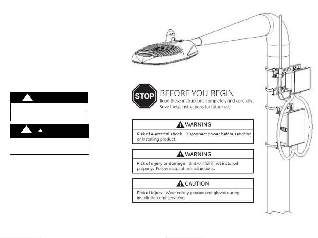
RISK OF ELECTRIC SHOCK
WARNING
INSTALL IN ACCORDANCE WITH
NATIONAL ELECTRIC CODE
WANING
WARNING
!
!
!
!
RISK OF INJURY. The gateway or cellular should be
mounted securely upon pole so that it will not move
or rotate freely.
Contents
Components ................................................................................................................................................. 3
Specifications ................................................................................................................................................ 4
Electrical Connections .................................................................................................................................. 5
Mounting Gateway and Cellular ................................................................................................................... 6
Powering Gateway & System Check ............................................................................................................. 7
Troubleshooting Cellular Modem ............................................................................................................... 10
Controller Installation ................................................................................................................................. 11
Components
The Gateway and Cellular Units have been packed so that no parts should have been damaged during transit,
inspect to confirm.
Gateway Package Includes:
ELWG0CXXGC – 120/277vac or ELWGHCXXGC – 347-480vac Gateway Unit (1pc)
Conduit fitting (2pcs) – mounted to enclosure;
Grey Gland (3pcs),
Antenna cable (1pc), - mounted to gland;
Antenna Pole (1pc), - to be installed;
Pole mounting bracket (2pcs), -mounted to enclosures;
Cellular Package (optional) Includes:
ELWM0CXV – Cellular Unit – 120/277v (1pc)
Conduit fittings 30” (2pcs), - mounted to enclosure;
Ethernet cable 42” (1pcs), mounted to fitting;
Power Cable 36” (1pc), mounted to fitting;
Pole mounting bracket (2pcs), mounted to enclosure;
Additional parts/tools (customer supplied)
Customer may require parts listed below:
o Conduit: Nonmetallic Type B liquid-tight ¾” Dia.
(e.g. Cooper LTCOND75NM100);
o Power Cable: 12AWG~18AWG per cord;
o Ethernet Cable: Cat5e outdoor Ethernet cable;
o Tools:
- Philips Head Screw driver;
- Steel Strap Cutter;
Optional:
o Caps over gland/conduit fittings;
o RIPLEY Ancillary Power Tap #5731

Specifications
Gateway
Gateway
Cellular
Part Number
ELWG0CXXGC
ELWGHCXXGC
ELWM0CXV
Input Voltage
120-277vac
347-480VAC
120-277VAC
Weight
7 lbs (3.18kg)
7 lbs (3.18kg)
8 lbs (3.63kg)
Dimensions (L x W x H)
7.6"x16"x11"
(193x406x280mm)
7.6"x16"x11"
(193x406x280mm)
15"x13"x7"
(381x330x178mm)
FCC ID
PUU90002
PUU90002
-
FCC Compliance
Part 15 Subpart C (Class B)
Part 15 Subpart C (Class B)
Part 15 Subpart C (Class B)
Mounting Height
24 ft. - 40 ft (8.2 m-12.2 m)
24 ft. - 40 ft (8.2 m-12.2 m)
24 ft. - 40 ft (8.2 m-12.2 m)
Temperature
-40°- 120°F (-40 - 50C)
-40°- 120°F (-40 - 50C)
-40°- 120°F (-40 - 50C)
Controller
Part Number
ELWN0A_._._1B_._AD
Input Voltage
120-277VAC
Weight
1 lb (0.45kg)
Dimensions (L x W x H)
1.5"x0.6"x0.6" (38.1x15.24x15.24mm)
FCC ID
PUU90003
FCC Compliance
FCC 47 CFR Part 15 C.247 (Class B)
IC ID
10798A-PUU90003
IC Compliance
RSS-247, Section 5
Mounting Height
Temperature
-40° to 120°F (-40 to 50C)
Controller Standard
ANSI 7 Pin
Controller Meter
0.5% Utility Grade
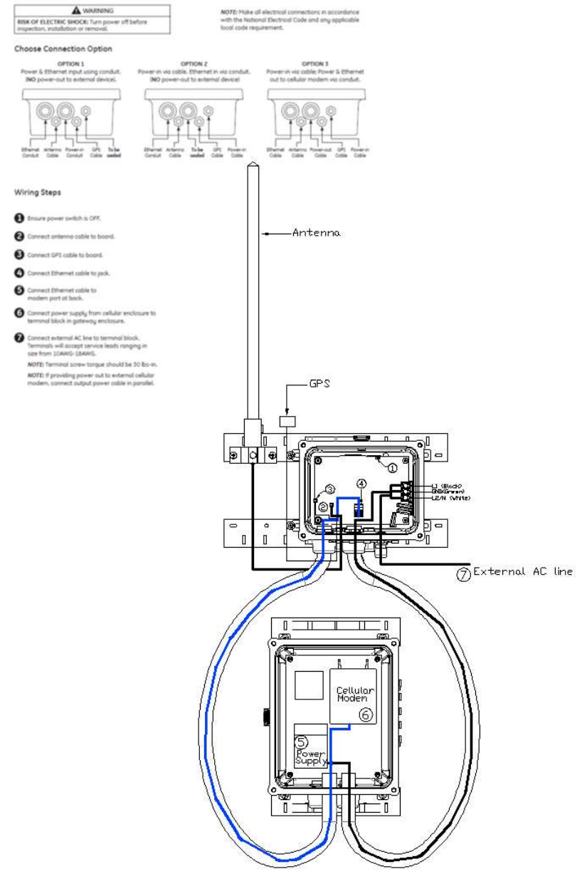
Electrical Connections
Depending on configuration of your LightGrid™ system select best option for making connections.
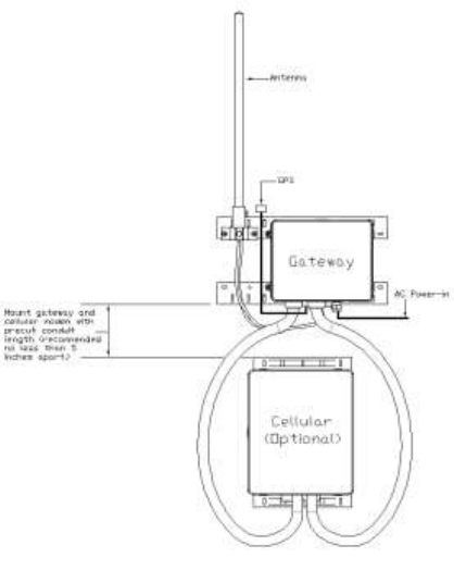
Mounting Gateway and Cellular
NOTE: Before mounting gateway to pole, ensure circuit powering the gateway is constant power and not
switched. Powering gateway with switched circuit will result in damaging gateway and unstable web application
for customer. If you have any questions during installation please contact our support team at 1-877-843-5590
or at lightgridsupport@ge.com
NOTE: Mount Gateway and Cellular Units securely in horizontal orientation to a vertical pole and inspect
periodically.
Carefully unpack unit from its packing. Properly inspect for defects before installing.
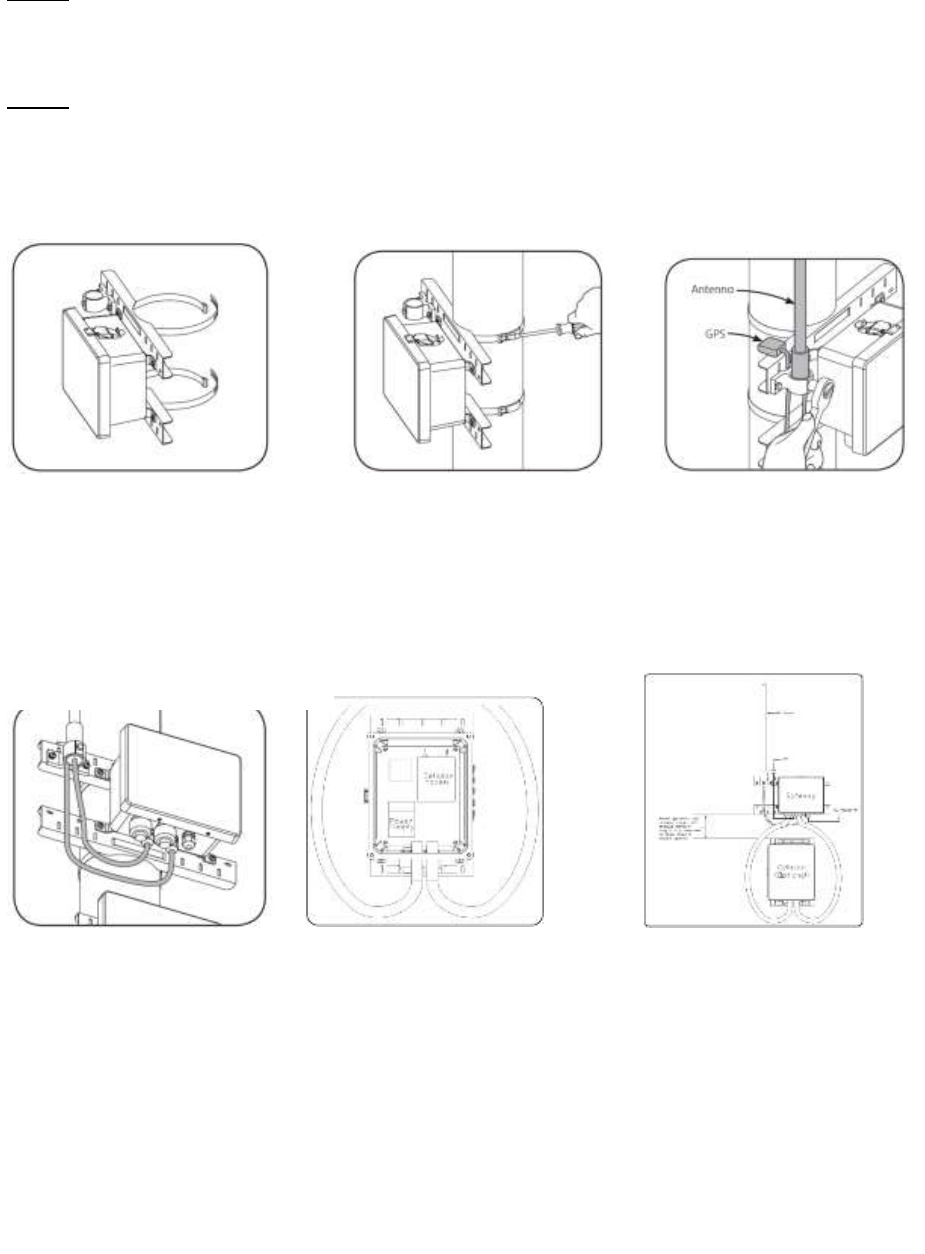
1. Before attaching gateway
enclosure to pole, ensure the
mounting band clams are correctly
oriented.
NOTE: Adjustable steel band allows
mounting on pole diameters up to
15 inches.
2. Attach gateway enclosure
to pole by tightening steel
band clamps. Fold or trim
excess metal band if needed.
3. Insert the antenna in the
mounting bracket and tighten
the mounting bolt (45 lbs-in
torque). Attach the GPS onto
the bracket.
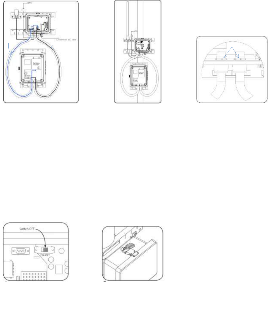
4. Insert GPS and antenna
wires through two glands
in bottom of gateway
enclosures.
5. Before mounting cellular
box to the pole, untighten the
conduit nut and insert the two
nonmetallic Type B liquid tight
conduits into the conduit
fittings. Using your hands
tighten the conduit fitting nut.
NOTE: Insert the conduit
completely into the conduit
fitting, no visible gaps should
be seen with conduit inserted
into conduit fitting.
6. Mount cellular unit
following the same practice as
mounting the Gateway Unit
over the same pole. Ensure
other end of the flexible
conduit fits into conduit fitting
hole of gateway.
Ethernet Cable
Power Cable
7. Insert Ethernet and Power
cable from gateway into
flexible conduit and terminate
Ethernet cable to modem, and
power cable to transformer.
See powering gateway and
system check for termination
information.
NOTE: Ensure you use
separate conduit for Ethernet
and power cable, do not mix
them in same conduit.
8. Untighten the conduit nut
on the gateway and insert the
two conduits from the
attached cellular modem box
to the gateway conduit fitting.
Using your hands tighten the
conduit fitting nut.
NOTE: Insert the conduit
completely into the conduit
fitting, no visible gaps should
be seen with conduit inserted
into conduit fitting. Failure of
installing the conduit correctly
will result in damage of
outside elements entering the
enclosures.
10. Locate the power switch
inside the gateway enclosure
and move to OFF position.
9. Inside the cellular modem
box check both ring nuts are
tight and the conduit fitting
does not rotate.
Metallic ring nut
11. Reattach cellular and
gateway enclosures covers.
Ensure the latches are
securely engaged securely
engaged.
Powering Gateway & System Check
NOTE: Confirm Gateway ON/OFF switch at OFF position.
NOTE: Ensure circuit powering Gateway is constant power and not switched. Powering gateway with switched
circuit will result in damaging gateway and unstable web application for customer. The system should be
powered on by following sequence as below: If you have any questions during system check please contact our
support team at 1-877-843-5590 or at lightgridsupport@ge.com
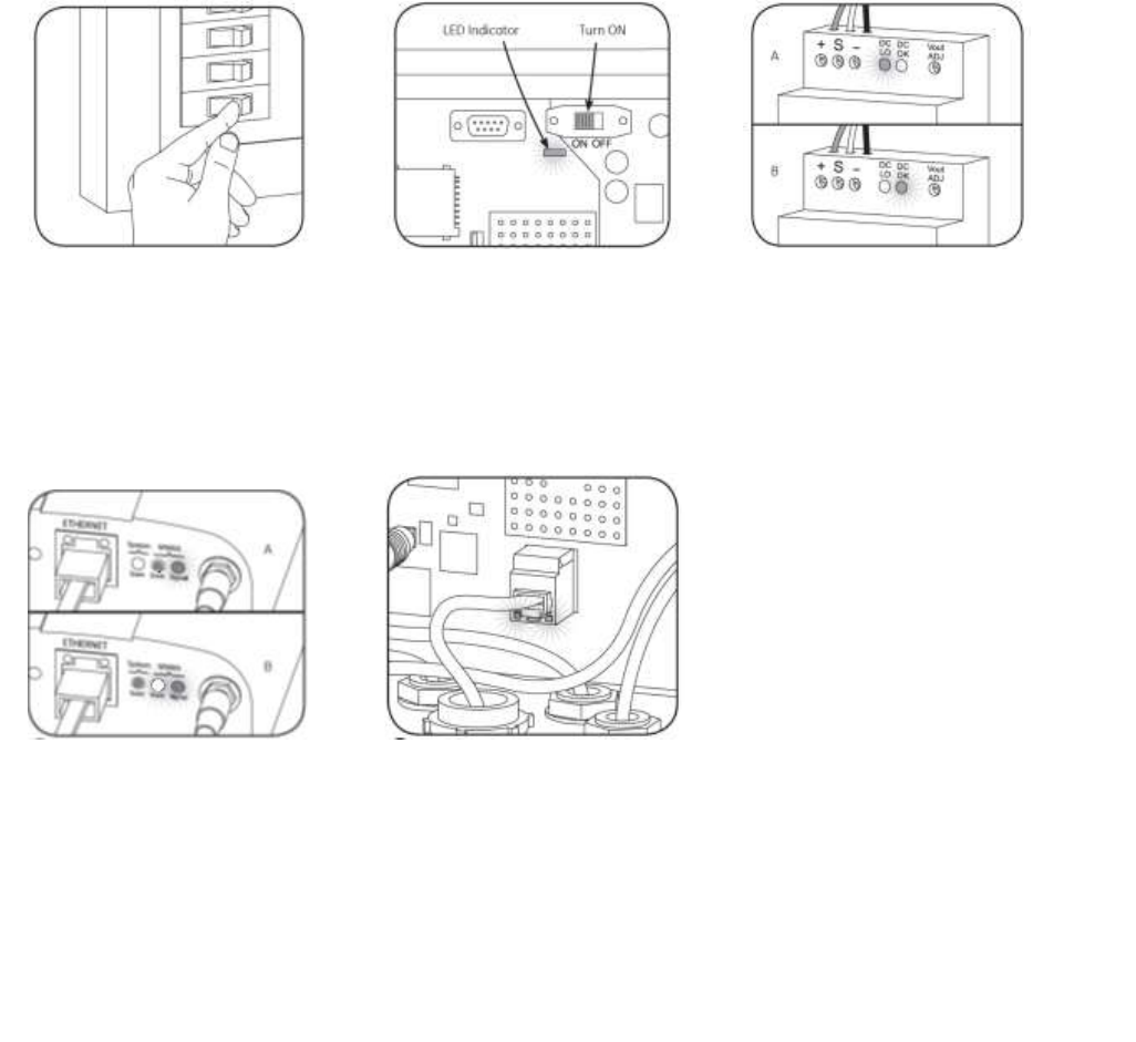
2. Turn the ON/OFF switch to ON
position. The LED indicator will
turn solid green indicating good
connection. Otherwise check all
wiring or consult with GE
Engineering Team.
1. Verify that power-in voltage is
120-277v. Turn on external
power source.
3. Inside the cellular enclosure,
check the power supply. A) DC/LO
will illuminate solid RED after
power up. B) DC/OK will
illuminate solid GREEN after
power stabilizes.
4. After 3 to 5 minutes, check the
Ethernet status of the modem
inside the cellular enclosure. A)
Two LED will be Yellow/Orange
indicates antenna signal reaches
midrange. B) Solid GREEN and
Orange combined indicate
antenna signal reaches wide
range.
5. Inside the gateway enclosure,
check Ethernet port connected
with YELLOW port LED blinking.
8. Reattach cellular and gateway
enclosures covers. Ensure the
latches are securely engaged.
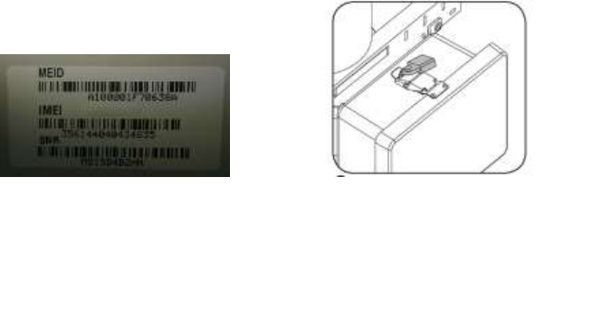
7. Locate cellular modem
MEID inside cellular modem
box door. Email all MEID to
LightGridSupport@ge.com
Troubleshooting Cellular Modem
In the event that technical support is unable to communicate to the cellular modem we will need to
troubleshoot the cellular modem as outlined below. During the troubleshooting process please contact our
technical support team at 1-877-843-5590.
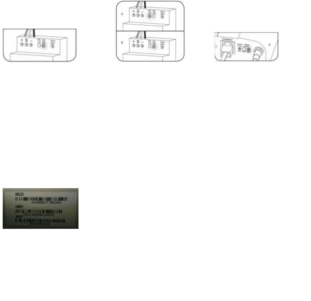
1. Inside the cellular enclosure,
check the power supply, the
DC/OK will be illuminated solid
GREEN. If LED is not illuminated
GREEN, check power source
and connections to power
supply terminal are secure.
Proceed to step two if power is
restored or reset to power
supply. If power supply DC/OK
is solid GREEN proceed to step
three.
2. If power source has been
restored or reset. A) DC/LO will
illuminate solid RED after power
up. B) DC/OK will illuminate solid
GREEN after power stabilizes.
3. Solid GREEN and ORANGE LED
combined indicate antenna signal
reaches wide range. If antenna
signal hasn’t reached wide range,
check if cellular modem antenna
is securely connected.
4. If all LED are correct, reset the
power to the cellular power
supply as outlined in step two.
Contact the technical support
team and supply them with the
MEID of the cellular modem
located inside door of the cellular
box.
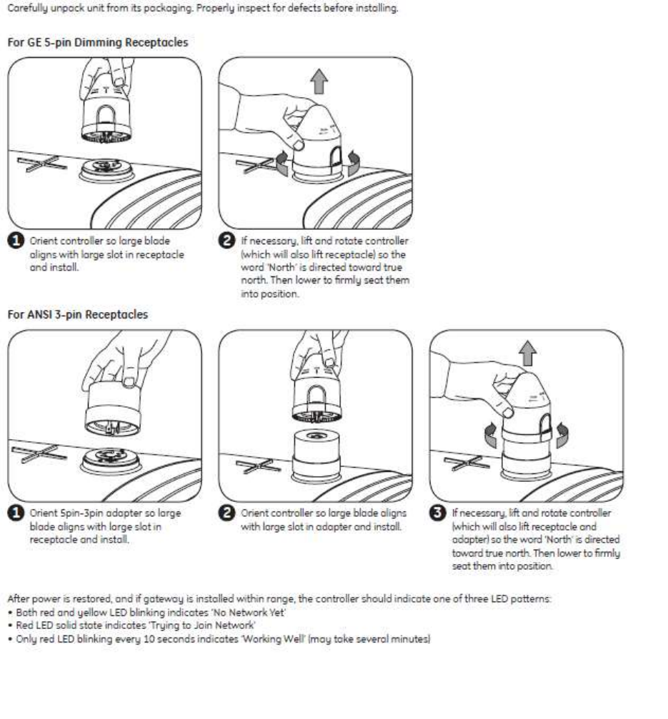
Controller Installation