Savi Technology 650R-V1 EchoPoint Reader User Manual EchoPointSR650 101
Savi Technology Inc EchoPoint Reader EchoPointSR650 101
Contents
- 1. Users Manual Revised
- 2. FCC Statements
Users Manual Revised

Savi Fixed Reader
SR-650-101
Installation Guide
Version 1.0
First edition February 2004
Part number 805-04399-001 Rev A
Documentation for Savi Fixed Reader SR-650-101, version 1.0
Copyright © 2004 Savi Technology, Inc. All rights reserved.
Information in this manual is subject to change without notice and does not represent a
commitment from the vendor. The software and/or databases described in this
document are furnished under a license agreement or nondisclosure agreement. The
software and/or databases may be used or copied only in accordance with the terms of
the agreement. It is against the law to copy the software on any medium except as
specifically allowed in the license or nondisclosure agreement.
Savi, Savi SmartChain, and Batch Collection are registered trademarks, and
EchoPoint, Savi GateReader, Savi MobileReader, Savi Retriever, SaviReader,
SaviTag, Savi Technology, SmartChain, SmartSeal, UDAP, and Universal Data
Appliance Protocol and are trademarks of Savi Technology, Inc.
Other product names mentioned in this guide may be trademarks or registered
trademarks of their respective owners and are hereby acknowledged.
Savi Technology, Inc.
615 Tasman Drive
Sunnyvale, CA 94089-1707
Phone: 1-408-743-8000
Facsimile: 1-408-543-8650
www.savi.com

Savi Fixed Reader SR-650 Installation Guide 3
Contents
1Introduction
Features . . . . . . . . . . . . . . . . . . . . . . . . . . . . . . . . . . . . . . . . . . . . . 6
Reader Description . . . . . . . . . . . . . . . . . . . . . . . . . . . . . . . . . . . . . 6
Tag Communication . . . . . . . . . . . . . . . . . . . . . . . . . . . . . . . . . . 6
Specifications . . . . . . . . . . . . . . . . . . . . . . . . . . . . . . . . . . . . . . . 7
Models and Options . . . . . . . . . . . . . . . . . . . . . . . . . . . . . . . . . 10
Contacting Customer Support . . . . . . . . . . . . . . . . . . . . . . . . . . . 12
2Savi Fixed Reader SR-650-101 Installation
Planning a Site . . . . . . . . . . . . . . . . . . . . . . . . . . . . . . . . . . . . . . . 13
Positioning Savi Fixed Readers . . . . . . . . . . . . . . . . . . . . . . . . . . 13
Mounting the Savi Fixed Reader . . . . . . . . . . . . . . . . . . . . . . . . . 15
Connecting Power Cables to the Savi Fixed Reader . . . . . . . . . . 16
Connecting the Network Cables . . . . . . . . . . . . . . . . . . . . . . . . . 17
Ethernet Connection . . . . . . . . . . . . . . . . . . . . . . . . . . . . . . . . . 17
Applying Power to the Savi Fixed Reader . . . . . . . . . . . . . . . . . . 19
Setting Up the Savi Fixed Reader SR-650-101 . . . . . . . . . . . . . . 20
Configuring Your PC’s IP Address . . . . . . . . . . . . . . . . . . . . . 20
Pinging the Savi Fixed Reader SR-650-101 . . . . . . . . . . . . . . 24
Configuring the Savi Fixed Reader SR-650-01 Parameters . . 26
Verifying Reader Communication . . . . . . . . . . . . . . . . . . . . . . . . 35

CHAPTER 1
Savi Fixed Reader SR-650 Installation Guide 5
Introduction
1
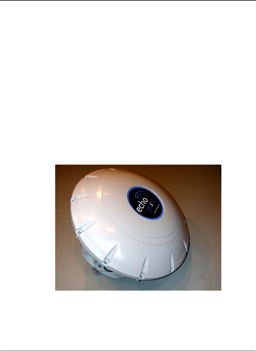
You can use the Savi® Fixed Reader SR-650-101 to scan, detect, and
collect tag information. The SR-650-101 Reader is designed to
communicate with all models of SaviTags, and forward the collected data to
the SmartChain™ Site Manager or Client Tools host platforms. You can
network multiple readers to cover large facilities.
Working with Savi Signposts, SR-650-101 Readers provide a complete
RFID solution for real-time, end-to-end visibility of goods and critical
assets moving through the supply chain.
Figure 1-1 Savi Fixed Reader SR-650

CHAPTER 1
Introduction
6
Features
◆Long-range, omnidirectional communication enables effective
monitoring of thousands of tagged items over a 100-meter radius—ideal
for yards, terminals, and warehouses.
◆Ethernet network connectivity supports wired and wireless installations,
allowing multiple readers to be easily networked together.
◆Universal Data Appliance Protocol (UDAP™) network protocol
provides interoperability with other data collection devices, including
bar code scanners and other RFID readers.
◆Seamless interface to Savi SmartChain® platform and applications
through the SmartChain Site Manager.
◆Rugged, weatherproof packaging for indoor and outdoor use.
Reader Description
The Savi Fixed Reader SR-650-101 has an omnidirectional read pattern
with an adjustable range of up to 300 feet (91.44 meters), and can be
networked to provide cellular coverage of a nearly unlimited area. Its power
source can be 92 to 250 VAC or 12 to 24 VDC. A portable tripod mount,
a solar power unit, or a cable for powering the reader from a vehicle are all
available for use with the SR-650-101 Reader.
The Savi Fixed Reader SR-650-101 operates at 433.92 MHz.
Tag Communication
The Savi Fixed Reader SR-650-101 can transmit control commands and
data over a UHF link to SaviTags. In return, the SaviTags transmit status
information, recognition codes, and data over the UHF link to the reader,
depending on the commands the tag received.

Reader Description
Savi Fixed Reader SR-650 Installation Guide 7
Specifications
The Savi Fixed Reader SR-650-101 can be mounted in permanent or
semipermanent sites, as well as in a mobile vehicle. SR-650-101 Readers
are designed for indoor or outdoor use.
Specification Description
Tag compatibility
All Savi RFID tags
UHF transceiver (uplink
and downlink)
Long-range, omni directional RF communication enables
effective monitoring of thousands of tagged items over a
100-meter radius
UHF operation UHF receiver for receiving the following information from
tags: status information, tag alarm messages, beacons,
UHF-initiated collection command responses or Signpost
initiated wakeup responses. Capable of receiving
recognition codes and data over a UHF link to ST-41x,
ST-645, and ST-65x tags
UHF transmitter capable of transmitting control
commands and data over a UHF link to ST-41x, ST-645,
and ST-65x tags
Architecture Single UHF board with two channels
Frequency 433.92 MHz
UHF Antennas Internal: Orthogonal (Omni) Dual Loop Antennas
Modulation
Data rate
Data coding
FSK, deviation +/- 35KHz for receive, +/- 50KHz for
transmit
27.8Kbps
Manchester
Communication range Typical transmit range is approximately 328 feet or 100
meters line of sight from the reader to ST-65x and ST-41x
tags. Typical transmit range is approximately 100 feet line
of sight from the reader to ST-645 tag
Typical receive range is approximately 328 feet or 100
meters line of sight from all Savi tags
Rx Signal Strength
Indicator (RSSI)
Supported

CHAPTER 1
Introduction
8
Maximum transmit power 0.1mW
-7 dBM after antenna gain
1 dBM before antenna gain
UHF air protocol BCS Commands, EBCS Commands (refer to Convergence
RFID Air Protocol document)
EchoPoint Air Protocol 2.1 (refer to EchoPoint Air
Protocol document)
✦Two-way UHF commands
✦Seal extension commands
Memory
Non-volatile On board non-volatile memory of 512Kbytes for interim
tag data
Power
AC Source Universal Power Supply
92-250 VAC, 50/60 Hz, 100 mA max
DC Source 12-24 VDC, 500 mA average (internally regulated)
Physical Enclosure
Size 30 cm (12 in.) diameter x 14 cm (5.5 in.)
Weight 1.9 kg (4.2 lbs)
Color Charcoal gray
Case material Polypropylene with UV inhibitors
Ty p e Rugged, weatherproof packaging for indoor and outdoor
use. Sealed to IP42, protection against objects larger than
1mm (.04 inches) in diameter and protection from water
falling as much as 15 degrees from vertical
Markings SR-650-101 Reader:
✦Savi name
✦Model Number
✦Serial ID (HRI and bar code)
✦Compliance label
✦HERO Label
Specification Description

Reader Description
Savi Fixed Reader SR-650 Installation Guide 9
Interfaces
Network interface ✦UDAP protocol over Ethernet 10Base-T.
✦Reader network supports wireless connectivity to host
computer via external 802.11b communications
Interfaces ✦Captive cable with RS232C interface and DB-9 female
connector
✦RS-485
✦RJ-45 10 Base-T Ethernet interface
RS232
✦Data rate
✦Flow control
✦Data format
✦RS232 signals
SMP Serial Communication Protocol
19.2 Kbps
CTS, half duplex communication
8 data bits, none parity, 1 stop bit
TXD, RXD, DTR, CTS
RS485
✦Data rate
✦Data format
✦RS485 signals
SMP Serial Communication Protocol
38.4 Kbps
8 data bits, none parity, 1 stop bit
2 wire differential
Indicators
LED displays Standard seven-segment LED display
Accessories
Mounting Savi Mounting Kit SRA-1001 (not included)
Savi Heavy Duty Mounting Kit SRA-1024 (not included)
Environment
Te m p e r a t u r e -32°C to +60°C operating
-40°C to +70°C storage
Humidity 100% condensing
Shock and Vibration
Vibration
Shock
MIL STD 810E Method 514.4, Category 10
MIL STD 810E Method 514.4, Category 10
Specification Description

CHAPTER 1
Introduction
10
Models and Options
Savi Readers are supplied with cables necessary for operation. Available
accessories include a solar power unit, a vehicle power cable, AC power
adapter and cables, spare batteries, a battery charger, and mounting
hardware. Contact your Savi Technical Service representative for
information about ordering additional equipment or accessories.
The table shows the Savi Fixed Reader models and options. All product
options are based on a common hardware and software platform with a
universal power supply. The difference between the product options is the
Regulatory Requirements
Radiated emission
(intentional)
U.S. emission standards as contained in FCC Part 15
Canada RSS210
European Community emission standards as contained in
EN 300 220 (433 MHz)
Electromagnetic Immunity ESD compliance
Exposed to 8 kV air discharge or 4 kV contact discharge in
accordance with EN 301 489-1
Radiated emission
(unintentional)
U.S. emissions standards as contained in FCC Part 15
Medical Device EMC, IEC 60601-1-2
European Community emission standards as contained in
EN 301 489-1
Safety approval U.S UL 1950
European EN 60950
Hazardous Location: Europe–EN50020
Ordnance safety HERO rated for 24” minimum safe separation distance
Markings Savi Logo
Product model and serial number
Safety (ETL/CE)
EMC Compliance (FCC/CE/IC)
Ordnance/HERO
Specification Description
Reader Description
Savi Fixed Reader SR-650 Installation Guide 11
type of power plug with which the unit is shipped. All models operate at
433.92 MHz.
Tabl e 1-1 Savi Fixed Reader SR-650-101 Reader models
Model Description Power/Plug
SR-650-101 Savi Fixed Reader SR-650-101 92-250 VAC 50/60 Hz, U.S. Plug
SR-650-101-2 Savi Fixed Reader SR-650-101 92-250 VAC 50/60 Hz, European
Plug
SR-650-101-3 Savi Fixed Reader SR-650-101 92-250 VAC 50/60 Hz, Japan Plug
SR-650-101-6 Savi Fixed Reader SR-650-101 92-250 VAC 50/60 Hz, Type 2
Plug
SR-650-101-7 Savi Fixed Reader SR-650-101 92-250 VAC 50/60 Hz, U.K. Plug
SR-650-101-8 Savi Fixed Reader SR-650-101 92-250 VAC 50/60 Hz, China Plug
SR-650-101-D Savi Fixed Reader SR-650-101 12 VDC
Pigtail wires
SR-650-101-T Savi Fixed Reader SR-650-101 Solar DC Input, Transportable

CHAPTER 1
Introduction
12
Contacting Customer Support
If you cannot find the information you need in this guide, contact Savi
Customer Support.
◆Call 1-888-994-SAVI (North America only) or 1-408-743-8888 between
9 a.m. and 5 p.m. Pacific time.
◆Send email to help@savi.com.
◆Check www.savi.com/support for information.
When you contact Savi Customer Support by telephone or email, have the
following information available:
◆Site location
◆Incident description
◆Estimated severity level of the incident
◆Model number and version
◆Serial number
◆Computer type (Gateway, Dell, etc.) and model
◆Operating system and service pack level
◆Network protocol

CHAPTER 2
Savi Fixed Reader SR-650 Installation Guide 13
Savi Fixed Reader
SR-650-101 Installation
2
Installing the Savi Fixed Reader SR-650-101 is a four-step process.
◆First, consult a site plan to determine the reader’s installation location.
◆Second, position the reader to enable the most efficient communication
range.
◆Third, connect power cables and network cables, and supply power.
◆Finally, verify network communication between the reader and the
computer.
Planning a Site
To plan a site you must conduct a site survey and plan the RFID network
configuration. Once the site plan is in place, refer to it to determine where to
install Savi Readers. Follow the directions in this manual to ensure proper
installation of each Savi Fixed Reader SR-650-101.
Positioning Savi Fixed Readers
Savi Fixed Readers are designed to operate in a wide variety of
environments. They are housed in rugged, weatherproof enclosures. In ideal
conditions (large, open, and unobstructed areas), Savi Readers can collect
tags up to 300 feet (91.44 meters) away.
An area can contain factors that limit the Savi Reader collection range,
including:
◆Asymmetrical shape to the collection area
◆Obstructions such as multiple walls, chained areas, solid-core doors, and
enclosures
CHAPTER 2
Savi Fixed Reader SR-650-101 Installation
14
◆RF interference from other equipment such as computers, walkie-talkies,
cellular phones, elevators, electrical motors, or other RF-emitting
devices
◆Savi Fixed Reader SR-650-101 mounting height of less than 15–30 feet
(4.572–9.144 meters)
◆Metal or RF-absorbent surface on the tracked item
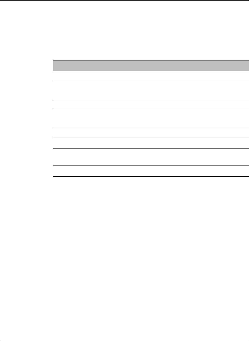
◆Tag location relative to the Savi Reader, such as behind a metal
obstruction (as illustrated in Figure 2-1) or stacked under multiple layers
Some of these factors may be beyond your control. The goal when
positioning the Savi Fixed Reader SR-650-101 is to optimize advantages
and reduce limitations to make the collection range as efficient as possible.
Figure 2-1 Impediment limiting the Savi Fixed Reader SR-650-101 collection range
If the location forces you to use a less-than-ideal position for the reader, the
collection range could be reduced, requiring additional readers.
Note:
If you must mount a Savi Fixed Reader on a wall, the collection
range may not extend to the opposite side of the wall. You may need a
second Savi Reader to monitor the area behind the wall.
Area of
limited
collection
ability
Metal wall
Savi Fixed Reader
mounted near a
ceiling

Mounting the Savi Fixed Reader
Savi Fixed Reader SR-650 Installation Guide 15
The collection range of the equipment depends on surrounding obstructions
that may shield tags from receiving reader signals or cause reflections into
locations outside the line-of-sight. As a first step, it is best to identify reader
installation locations using a line-of-sight model to any assets equipped
with tags. You may need to experiment to cover the desired area.
To optimize performance:
◆Locate the reader approximately 15 to 30 feet above the ground.
◆Avoid installations within 6 feet (2 meters) of metal surfaces, such as
temporary buildings or large steel doors.
Caution:
The Reader must be mounted in a horizontal plane with its dome
directed downwards, as shown in Figure 2-1. Other orientations will
distort the field patterns and make performance unpredictable. Maintain
the horizontal orientation when using the wall mount kit, tripod, or other
mounting hardware.
Mounting the Savi Fixed Reader
You can mount the Savi Fixed Reader SR-650-101 using any of the
associated mounting hardware available from Savi Technology. However,
you might want to be sure that the reader is operational and verified on the
network before mounting it in any hard-to-reach position.
The mounting kit available from Savi Technology includes hardware to
mount a Savi Fixed Reader on a pole (wooden, metal, or concrete), I-beam,
wall, or a tripod. Refer to the instructions included with the mounting kit for
proper installation.
RFID hardware can be physically attached in any position or location. If
your installation requires a special attachment, Savi can develop and
manufacture a custom fixture.
If you have problems communicating with the Savi Fixed Reader during or
after the installation, refer to Chapter 3, “Maintenance,” for troubleshooting
procedures.

CHAPTER 2
Savi Fixed Reader SR-650-101 Installation
16
Connecting Power Cables to the
Savi Fixed Reader
Note:
While the Savi Fixed Reader SR-650-101 is rated for use in severe
environments, the power and network connector seals may deteriorate
with repeated installation and removal. Therefore, Savi recommends the
use of heat shrink tubing (Savi part number 680-02423-001) for units
subject to outdoor use.
When connecting the Savi Fixed Reader’s power cable, be sure to check
any relevant configuration or wiring diagrams beforehand.
The power source can be 12 to 24 VDC or 92 to 250 VAC. The socket-
outlet should be installed near the equipment and should be easily
accessible. The Savi Fixed Reader SR-650-101 does not require adjustment
or modification for different power sources. An appropriate power cable is
supplied, based on the requirements specified when the order was placed.
You can also power the Savi Fixed Reader SR-650-101 from a Savi Solar
Power Module or by vehicle power. A fixed-length, molded cable is
supplied with the Solar Power Module. You can purchase the Vehicle
Power Cable as an accessory item.
The appropriate power cable for the AC power source should be included
with the reader.
To connect the power cable to the reader:
1. If installing the Savi Fixed Reader SR-650-101 in an outdoor location,
slide heat shrink tubing onto the power cable before connecting the
cable to the reader. Follow the instructions included with the heat shrink
kit to apply the tubing to the cable.
2. On the Savi Fixed Reader, plug the cable’s female connector into the
power input socket. See Figure 2-2.
a. Turn the connector to align its notch on the side nearest the Savi
Fixed Reader’s dome.
b. Firmly push the locking ring forward and rotate it clockwise to lock
the connector.
Connecting the Network Cables
Savi Fixed Reader SR-650 Installation Guide 17
Figure 2-2 Power Connector
Connecting the Network Cables
Before you connect the Savi Fixed Reader’s network cables, check any
relevant configuration or wiring diagrams.
Note:
While the Savi Fixed Reader SR-650-101 is rated for use in severe
environments, the power and network connector seals may deteriorate
with repeated installation and removal. Savi recommends the use of heat
shrink tubing (Savi part number 680-02423-001) for units subject to
outdoor use.
Ethernet Connection
You can connect the Savi Fixed Reader SR-650-101 directly to a network
hub via the built-in Ethernet connection. The Readers are the source of
RFID tag read and service events. SmartChain Site Manager records, stores,
and forwards these events to Savi SmartChain application software.
SmartChain Site Manager also sends commands for reader management or
control logic. The readers communicate with SmartChain Site Manager
using Universal Data Appliance Protocol (UDAP).
CHAPTER 2
Savi Fixed Reader SR-650-101 Installation
18
SmartChain Site Manager and applications are available separately from
Savi Technology.
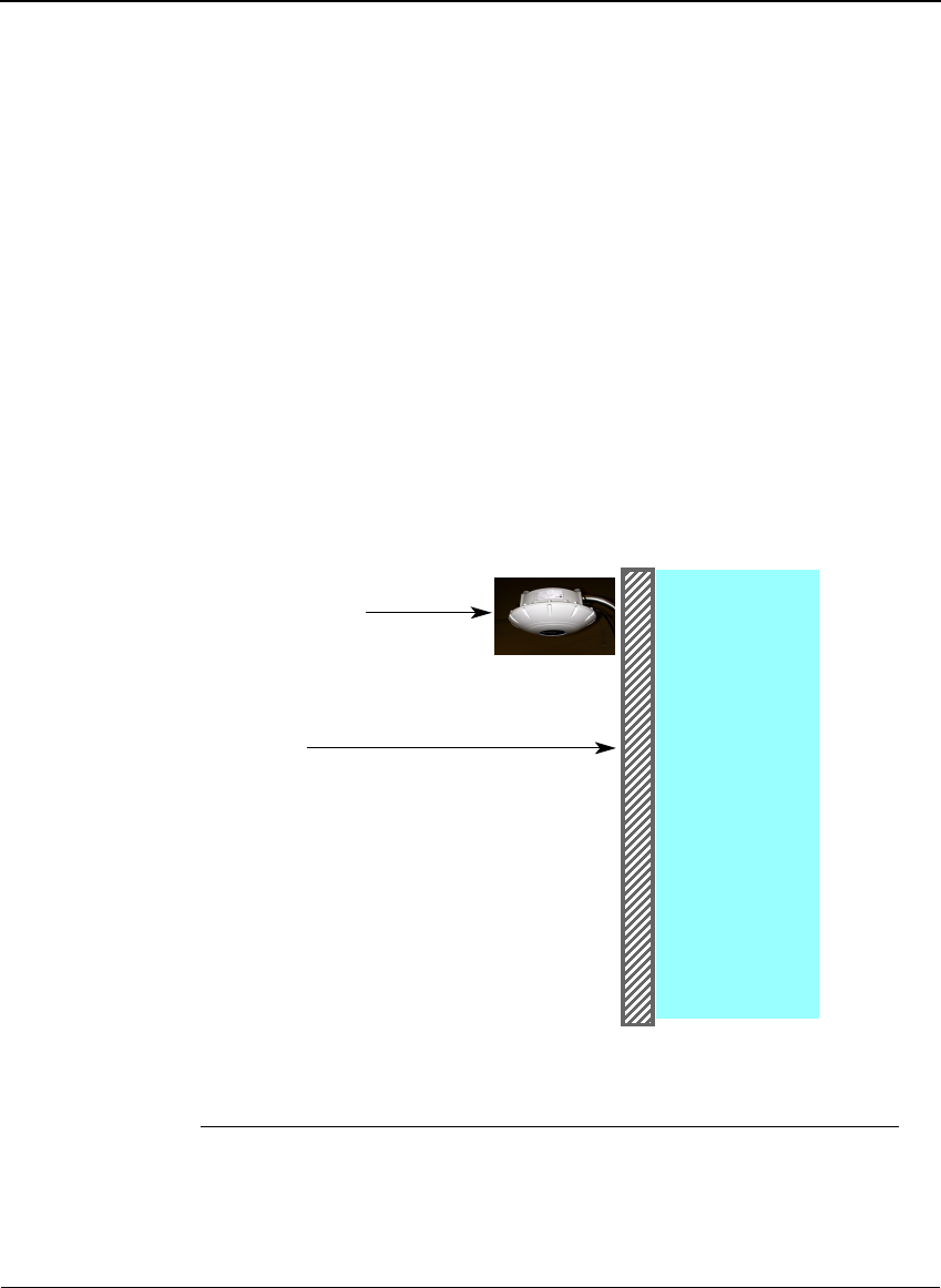
Connect the RJ-45 connector of the Ethernet cable from the SR-650-101
Reader to the Ethernet hub.
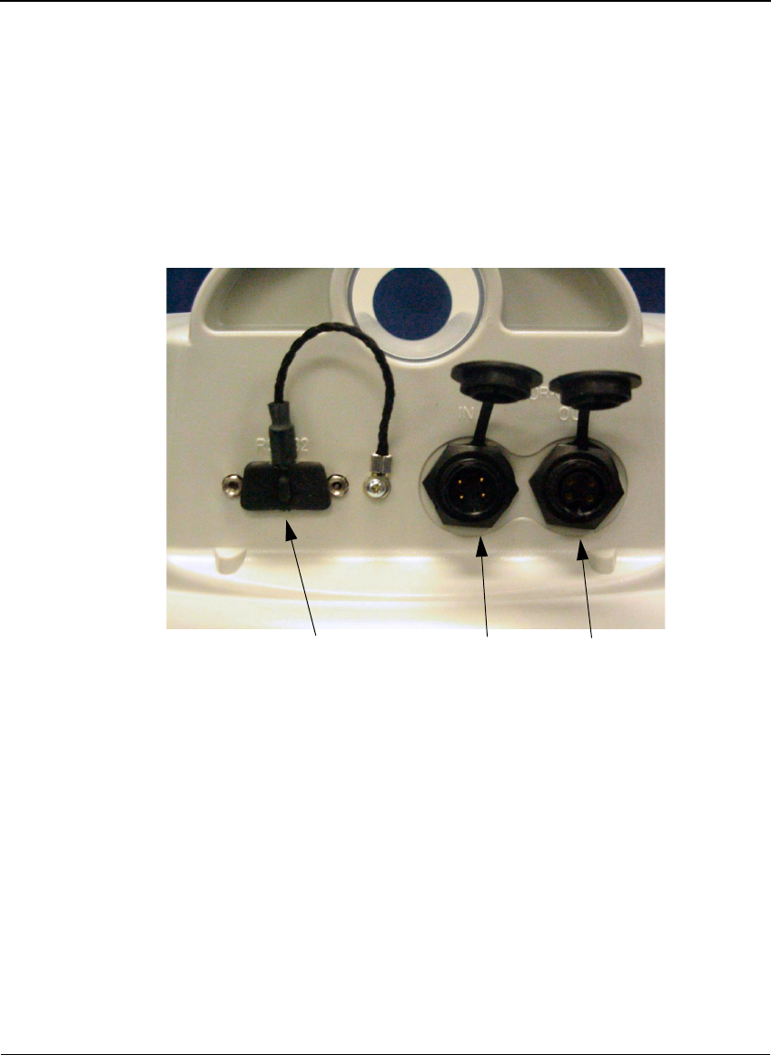
Figure 2-3 Network connector and RS-232 ports
RS-232 port Network In Network Out
Applying Power to the Savi Fixed Reader
Savi Fixed Reader SR-650 Installation Guide 19
Applying Power to the Savi Fixed
Reader
After connecting power and network cables, apply power to the Savi Fixed
Reader by connecting the male connector end of the power cable to the
appropriate power source, such as the Savi Solar Power Module or an AC
outlet.
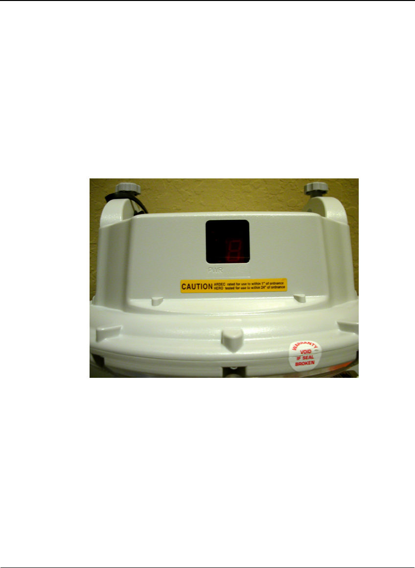
Figure 2-4 Savi Fixed Reader SR-650-101 LED display panel
To confirm that power is present in the Reader:
1. Observe the indicators and the seven-segment display on the LED
display panel. The power indicator should be illuminated whenever
power is present.
a. During the initial power-on sequence, the Savi Fixed Reader displays
its identification number (ID) in the LED display as a sequence of
five digits.
Savi Fixed Reader ID number 1234 displays the numbers 0, then 1,
then 2, then 3, and then 4 in sequence during the initialization
process.

CHAPTER 2
Savi Fixed Reader SR-650-101 Installation
20
b. After the ID display, two indicators flash at different rates. One is the
center bar of the segmented display and the other is a small indicator
within the segmented display. If the indicators fail to flash, the Savi
Fixed Reader is non-operational.
2. If at any time you are not sure that the Savi Fixed Reader is operating
properly, reset the reader by disconnecting and then reconnecting the
power source.
After resetting the Savi Fixed Reader SR-650-101, it should repeat the
power-on sequence described above.
The Savi Fixed Reader is now ready for you to verify communication
functions.
Note:
The Savi Fixed Reader SR-650-101 has a watchdog sensor that
automatically resets the reader if power fluctuations or other interruptions
occur that might affect the reader’s performance.
Setting Up the Savi Fixed Reader
SR-650-101
The Savi Fixed Reader SR-650-101 has an integrated network interface.
Note:
Keep in mind that if you connect multiple readers to the same
network, they will all have the same default IP address of 10.7.19.11 and
may create network conflicts.
Once the hardware is installed, you set the IP address for the Savi Fixed
Reader SR-650-101, ping the reader to verify its connection, and configure
the Savi Fixed Reader SR-650-101 parameters.
Configuring Your PC’s IP Address
To set up the proper IP addresses, you must first configure the host
computer to be able to communicate with the Savi Fixed Reader
SR-650-101.
To specify the IP Address:
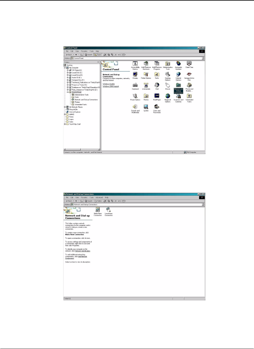
1. At the host computer desktop, select Start > Settings > Control Panel.
Setting Up the Savi Fixed Reader SR-650-101
Savi Fixed Reader SR-650 Installation Guide 21
Figure 2-5 Control Panel window
2. Double-click the Network and Dial-Up Connections icon to display
the Network and Dial-Up Connections window.
Figure 2-6 Network and Dial-Up Connections window
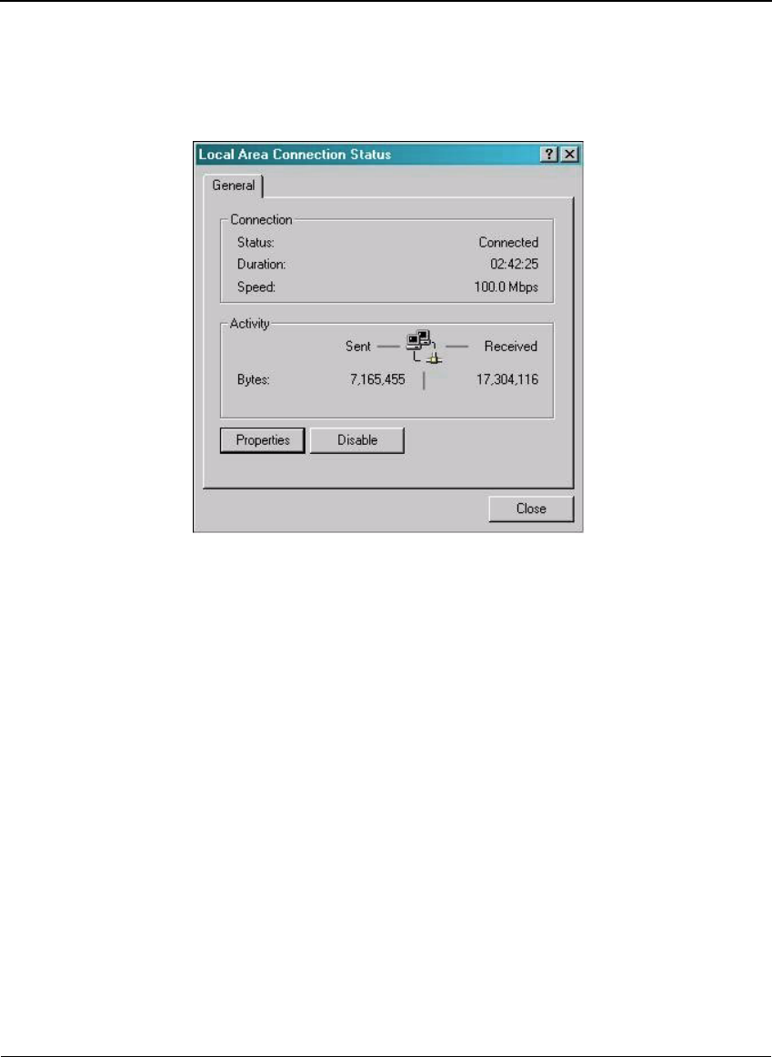
3. Double-click the Local Area Connection icon.
The Local Area Connection Status window appears.
CHAPTER 2
Savi Fixed Reader SR-650-101 Installation
22
Figure 2-7 Local Area Connection Status window
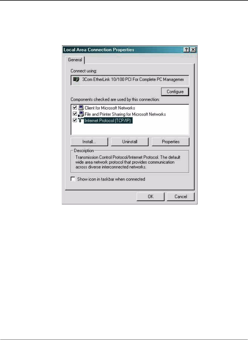
4. Click Properties to display the Local Area Connection Properties
window.
Setting Up the Savi Fixed Reader SR-650-101
Savi Fixed Reader SR-650 Installation Guide 23
Figure 2-8 Local Area Connection Properties window
5. Double-click Internet Protocol (TCP/IP).
CHAPTER 2
Savi Fixed Reader SR-650-101 Installation
24
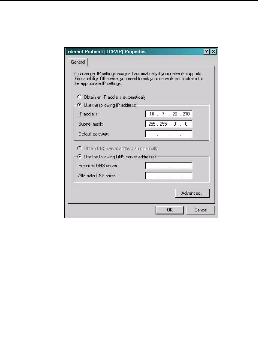
Figure 2-9 Internet Protocol TCP/IP Properties window
6. Make the necessary changes to the IP address and Subnet mask
addresses and click OK.
The default IP address for the Savi Fixed Reader SR-650-101 is
10.7.19.11. You can set the host IP address as 10.7.20.218, the Subnet
mask to 255.255.0.0, and leave all others blank.
7. Close all windows and return to the desktop.
Pinging the Savi Fixed Reader SR-650-101
You need to check the network connection from your computer to the Savi
Fixed Reader SR-650-101. You can either use an Ethernet cross connect
cable from your PC’s Ethernet port to the Ethernet cable from the Savi
Fixed Reader SR-650-101 (with a coupler) or connect both your PC and the
Setting Up the Savi Fixed Reader SR-650-101
Savi Fixed Reader SR-650 Installation Guide 25
Savi Fixed Reader SR-650-101 to a live local area network. You use
the command prompt to ping the reader.
To ping the reader:
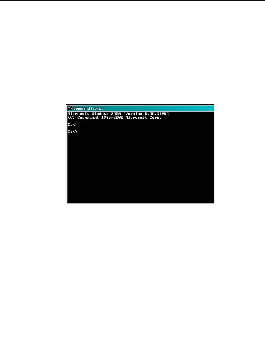
1. At the host computer desktop, select Start > Programs > Accessories >
Command Prompt to open a DOS session.
Figure 2-10 Command Prompt window
2. Type ping 10.7.19.11 (this is the default IP address of the reader) and
press Enter.
Pinging proceeds until it completes all cycles.
CHAPTER 2
Savi Fixed Reader SR-650-101 Installation
26
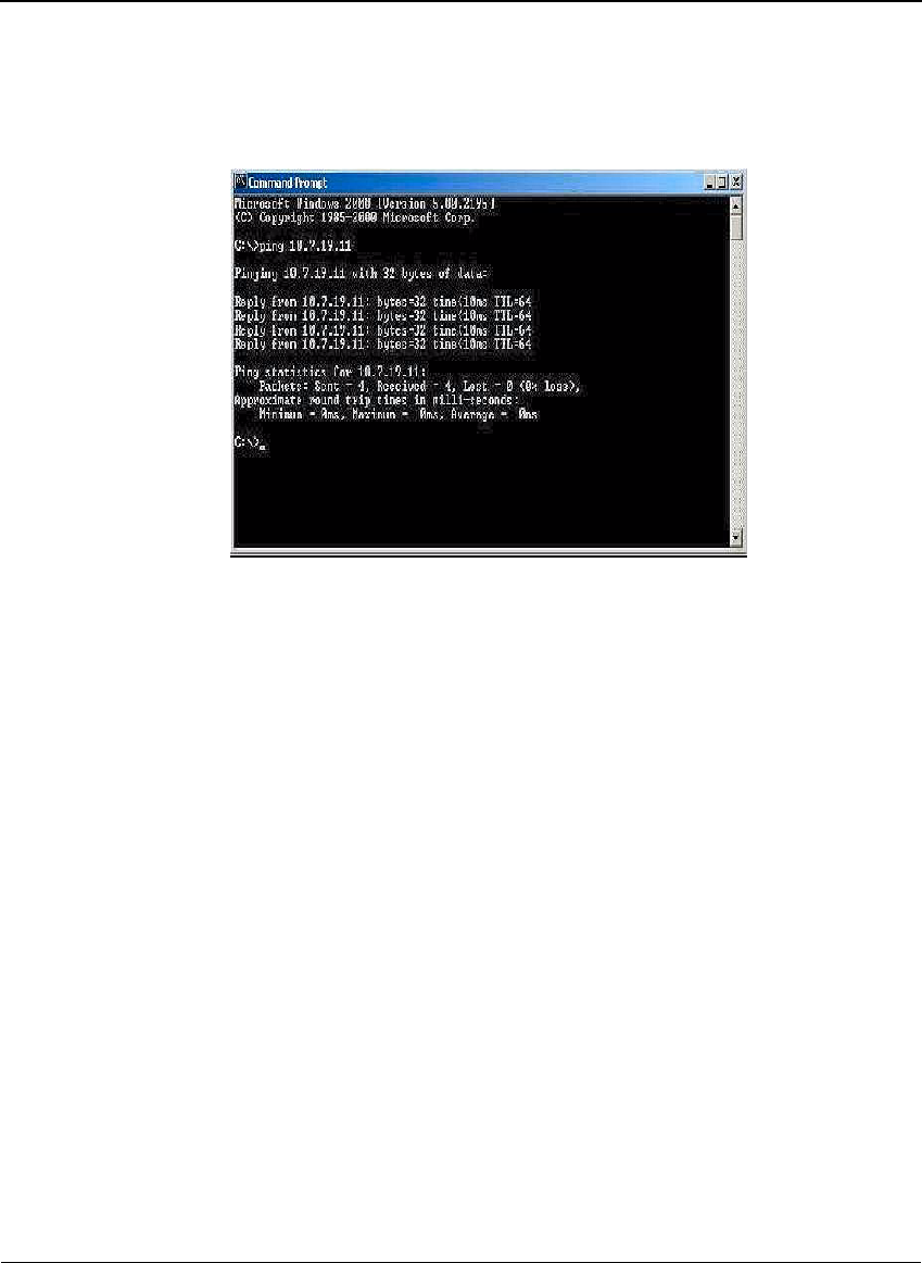
Figure 2-11 Command Prompt window with completed ping
3. Upon successfully pinging the reader, close the Command Prompt
window and begin the Savi Fixed Reader SR-650-101 setup process.
Configuring the Savi Fixed Reader SR-650-01
Parameters
In this section you use Microsoft Telnet Client to connect to the reader and
set up the reader parameters. Telnet Client software allows a computer to
connect to a remote Telnet server and run applications on that server.
To connect to the reader and set up the parameters:
1. At the host computer desktop, select Start > Programs > Accessories >
Command Prompt to open a DOS session.
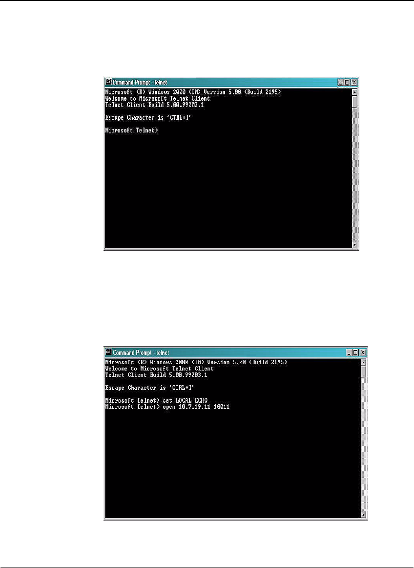
2. At the C:\ prompt, type telnet and press Enter to open a Telnet session.
Setting Up the Savi Fixed Reader SR-650-101
Savi Fixed Reader SR-650 Installation Guide 27
Figure 2-12 Telnet Client window
3. At the first prompt, type set LOCAL_ECHO and press Enter to enable
the echo so you can verify key entries.
4. At the second prompt, type open 10.7.19.11 10011 and press Enter to
connect to the reader.
Figure 2-13 Telnet connection commands
CHAPTER 2
Savi Fixed Reader SR-650-101 Installation
28
You see a blank Command Prompt - telnet window if the telnet
connection is successful.
Now you can run commands to modify the properties of the reader.
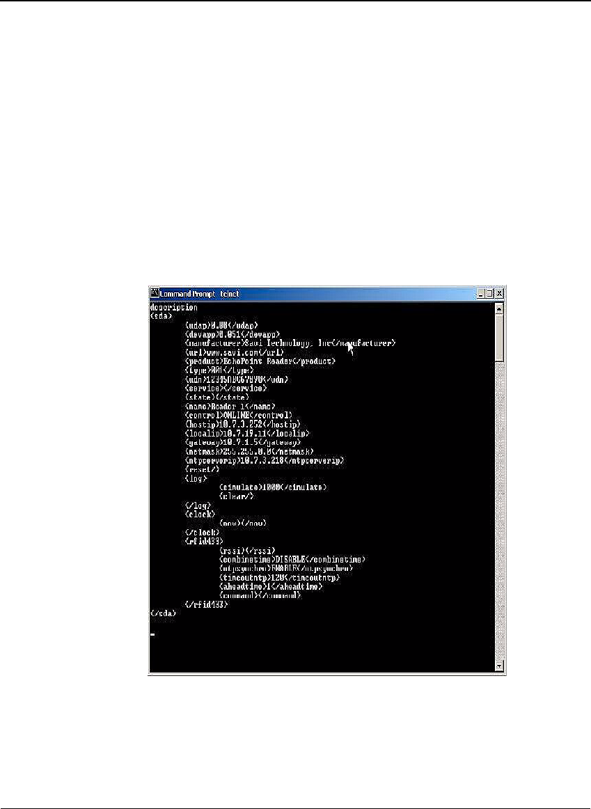
To view existing reader properties:
1. At the cursor, type description and press Enter.
The current properties of the reader appear that you can view or modify.
Not all properties can be modified.
Figure 2-14 Description of reader properties
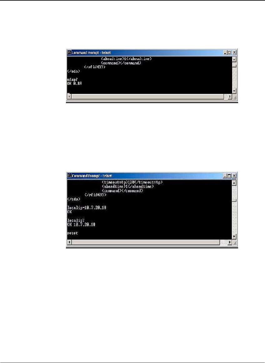
2. At the cursor, type udap? and press Enter to display the UDAP
firmware’s value.
The property udap is a read-only property; you cannot modify it.
Setting Up the Savi Fixed Reader SR-650-101
Savi Fixed Reader SR-650 Installation Guide 29
Figure 2-15 Telnet UDAP value display
To assign a new local IP address to the reader and modify gateway and
netmask addresses:
1. At the cursor, type localip=10.7.20.118 (or whatever valid IP address
you want to assign) and press Enter to set the reader IP address to the
input one.
Figure 2-16 Telnet local IP address display
2. Type reset and press Enter to cause the IP address to take effect.
Now you can use Telnet to connect to the reader at the new IP address.
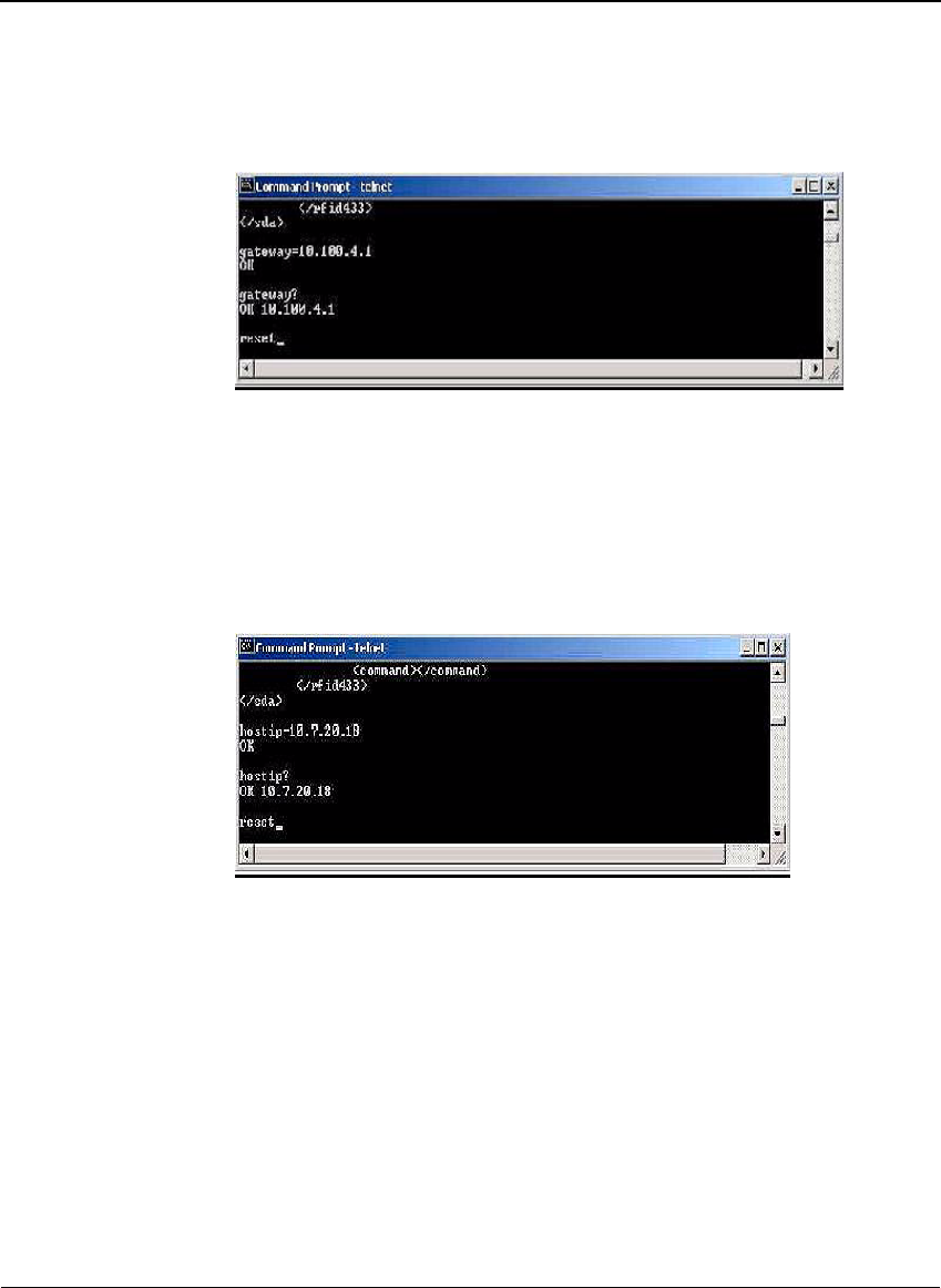
3. Type gateway=10.100.4.1 (or whatever valid IP address you want to
assign) and press Enter to set the reader gateway IP address to the input
one.
CHAPTER 2
Savi Fixed Reader SR-650-101 Installation
30
Figure 2-17 Telnet Gateway IP address display
4. Type reset and press Enter to make the gateway IP address take effect.
5. Type hostip=10.7.20.18 (or whatever valid IP address you want to
assign to the SmartChain Site Manager) and press Enter to set the
reader host IP address to the input one. This will point the Savi Fixed
Reader SR-650-101 to the Site Manager’s IP address.
Figure 2-18 Telnet Host IP address display
6. Type reset and press Enter to apply the host IP address.
The host is the computer to which the reader sends the event data.
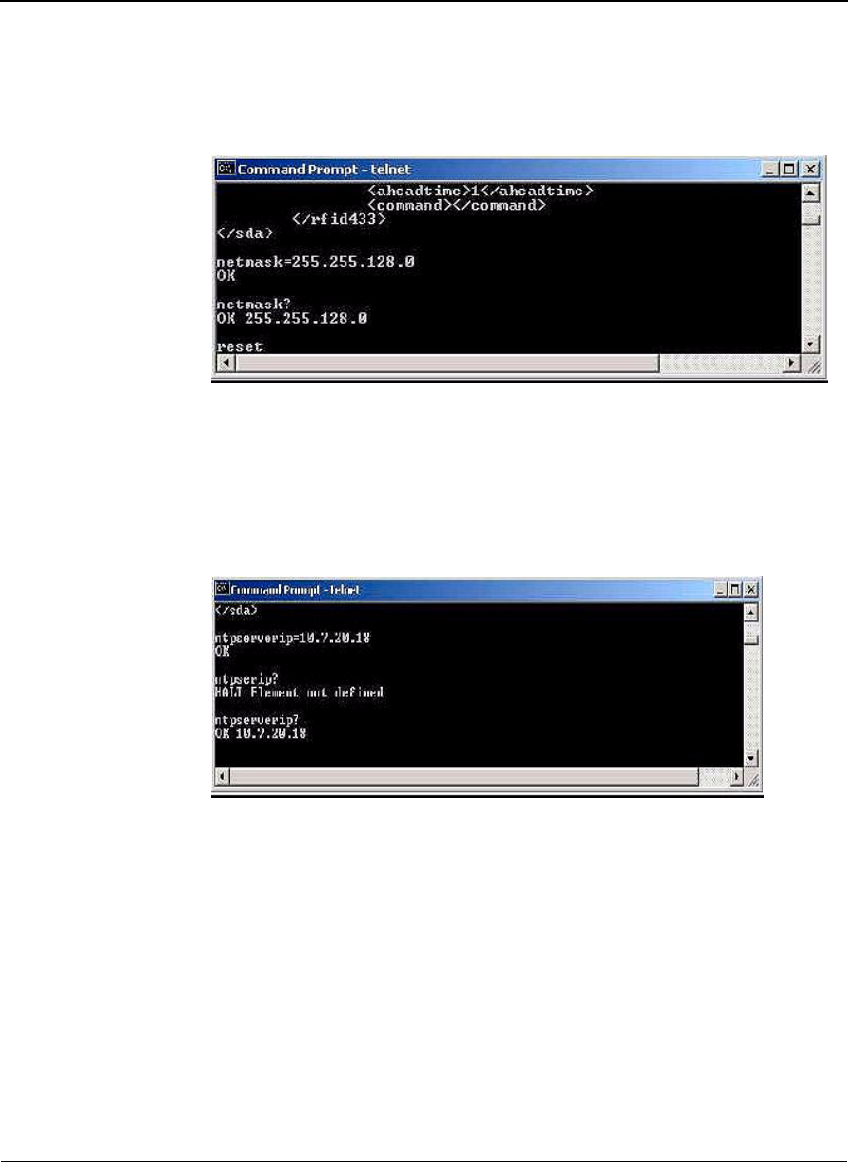
7. Type netmask=255.255.128.0 (or whatever valid mask you want to
assign) and press Enter to set the reader network mask to the input one
as depicted in Figure 2-19.
Setting Up the Savi Fixed Reader SR-650-101
Savi Fixed Reader SR-650 Installation Guide 31
Figure 2-19 Telnet network mask display
8. Type reset and press Enter to make the netmask take effect.
9. Type ntpserverip=10.7.20.18 (or whatever valid NTP address you want
to assign) and press Enter to set the NTP server IP address that the
reader will listen to.
Figure 2-20 Telnet NTP server IP address display
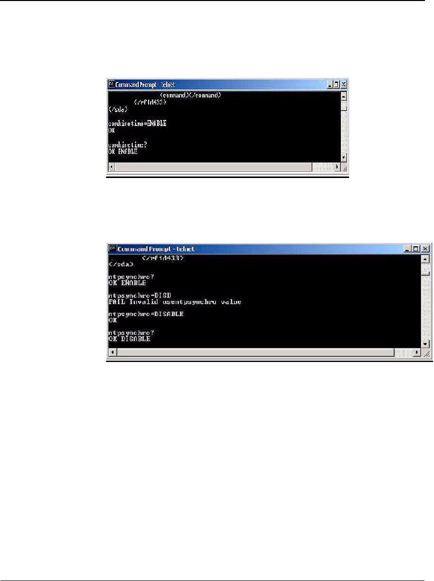
To set reader parameters:
1. Type combinetime=ENABLE (DISABLE) and press Enter to enable
(disable) the time of event data from the reader to combine with the time
of the tag received from the Signpost.
CHAPTER 2
Savi Fixed Reader SR-650-101 Installation
32
Figure 2-21 Telnet combine tme command
2. Type ntpsynchro=ENABLE (DISABLE) and press Enter to enable
(disable) the reader time and date to synchronize with the NTP server.
Figure 2-22 Telnet NTP server synchronization command
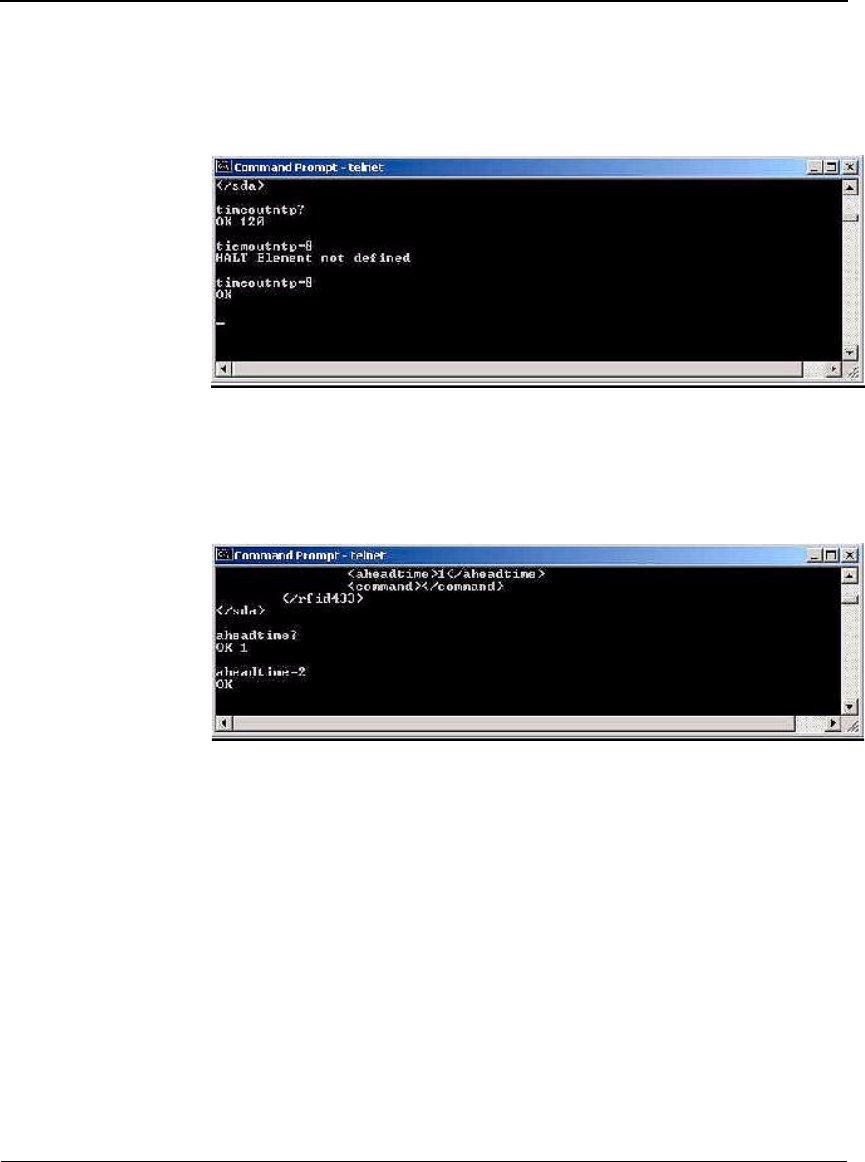
3. Type timeoutntp=8 (unit: minutes) and press Enter to set the period (in
minutes) for which, if the reader has not received time information, it
will assume it has lost time synchronization with the NTP server.
Setting Up the Savi Fixed Reader SR-650-101
Savi Fixed Reader SR-650 Installation Guide 33
Figure 2-23 Telnet NTP server time out command
4. Type aheadtime=2 (unit: seconds) and press Enter to set the time (in
seconds) that the reader will take ahead of the synchronized NTP server
time.
Figure 2-24 Telnet reader ahead time command
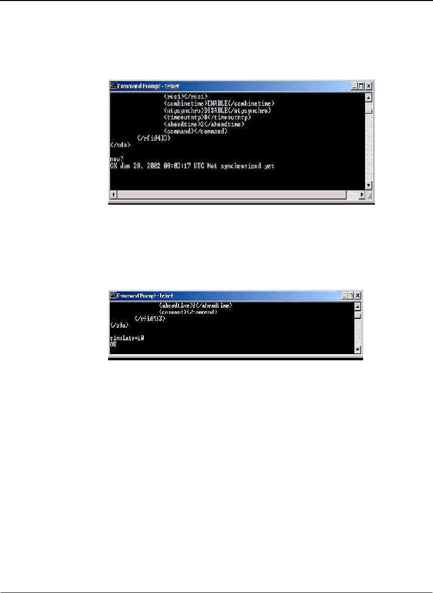
5. Type now? and press Enter to display the current time.
If the reader is not set to synchronize with an NTP server then you can
also set the time with this command.
CHAPTER 2
Savi Fixed Reader SR-650-101 Installation
34
Figure 2-25 Telnet time command
6. Type simulate=10 and press Enter to generate 10 simulated events.
If you have a daemon listening to the event on the host computer, it will
receive the events.
Figure 2-26 Telnet simulate command
7. Type reset and press Enter to reset the Savi Fixed Reader SR-650-101
with all the new parameters.

Verifying Reader Communication
Savi Fixed Reader SR-650 Installation Guide 35
Verifying Reader Communication
To confirm that an Savi Fixed Reader SR-650-101 is installed and
functioning correctly, it is necessary to verify that the reader:
◆Can communicate with the SmartChain Site Manager (verifies that the
reader is detected on the network)
◆Can collect tags in the collection area
Once the Savi Fixed Reader is installed, refer to the Guide to
SmartChain Site Manager for instructions on testing the operation of the
reader.

CHAPTER 2
Savi Fixed Reader SR-650-101 Installation
36

CHAPTER 3
Savi Fixed Reader SR-650 Installation Guide 37
Maintenance
3
With minimal care, a Savi Fixed Reader SR-650-101 should perform
flawlessly. However, in the event that a problem with a Savi Fixed Reader
occurs, the procedures in this chapter should help you troubleshoot it.
Warning:
Changes or modifications to the equipment that are not
expressly approved by Savi Technology could void the warranty and the
authority to operate the equipment.
Using the equipment in a manner not specified by the manufacturer might
impair the protection that the equipment provides.
Savi Technology is not responsible for radio/TV interference caused by
using unauthorized cable or by making unauthorized changes to this
equipment.
Repair and Maintenance
The Savi Fixed Reader SR-650-101 is designed to be maintenance-free. It is
manufactured with the highest-quality components and is thoroughly tested
before delivery.
Troubleshooting
The table in this section lists causes and solutions to problems that could
occur with the Savi Fixed Reader SR-650-101.
In the unlikely event that a Savi Fixed Reader fails or problems occur that
simple troubleshooting cannot solve, Savi Technical Support may
recommend that the Reader be returned to Savi Technology.

CHAPTER 3
Maintenance
38
Problem Solution
No power
(indicator light is not
blinking)
✦Confirm that power is available by checking any
circuit breakers, power switches, or safety switches.
✦If AC-powered, verify the presence and voltage of
the power by connecting a test unit to the power
source. Check the AC fuses.
✦If DC-powered or solar powered, verify that the
external supply is supplying 12 to 24 VDC.
✦Verify that the power cable is securely plugged into
the power source and the Fixed Reader input.
✦Try a different power source.
✦Replace the power cable.
Network cables
damaged or
disconnected
✦Verify that the network cable is securely plugged
into the Fixed Reader.
✦Verify that the network cable is securely plugged
into the SR-650-101.
✦Check cables for physical damage.
ID needs confirmation ✦Reset the power (by disconnecting and then
reconnecting the live power source) to view the
Fixed Reader serial number, which flashes in
sequence after the reader is reset. See “Applying
Power to the Savi Fixed Reader” on page 19
✦Compare the Fixed Reader serial number to the
ID used in the management software and on the
printed label.
Unknown ✦Turn power off and then back on.
✦Call Savi Technical Support.

Technical Support
Savi Fixed Reader SR-650 Installation Guide 39
Technical Support
If your Savi Fixed Reader SR-650-101 presents a problem that neither this
manual nor troubleshooting tips can help you solve, you can contact Savi
Technical Support in either of two ways:
◆Telephone 1-888-994-SAVI (7284) between 8:00 a.m. and 5:00 p.m.,
Pacific Time
◆Or send e-mail to help@savi.com at any time
Whether you contact Savi by telephone or e-mail, please have the exact
sequence of operations (if possible) that caused the problem and the
following information available:
◆Site location
◆Incident description
◆Estimated severity level of the incident
◆Model number and version
◆Serial number
◆Computer type (Gateway, Dell, etc.) and model
◆Operating system and service pack level
◆Network protocol

CHAPTER 3
Maintenance
40