Savi Technology 650R-V2 RFID Tag Interrogator User Manual EchoPointSR650 101
Savi Technology Inc RFID Tag Interrogator EchoPointSR650 101
UserManual.wiki
>
Savi Technology
>
650R-V2 User Manual
>
user manual pt 2
Contents
1.
user manual pt 1
2.
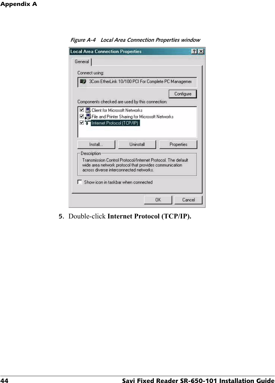
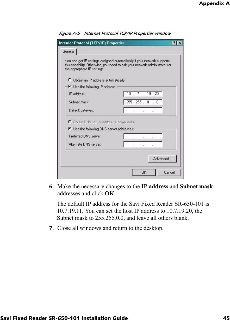
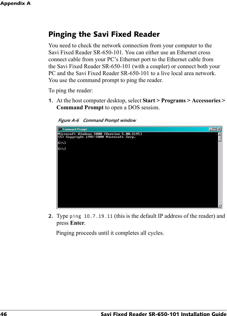
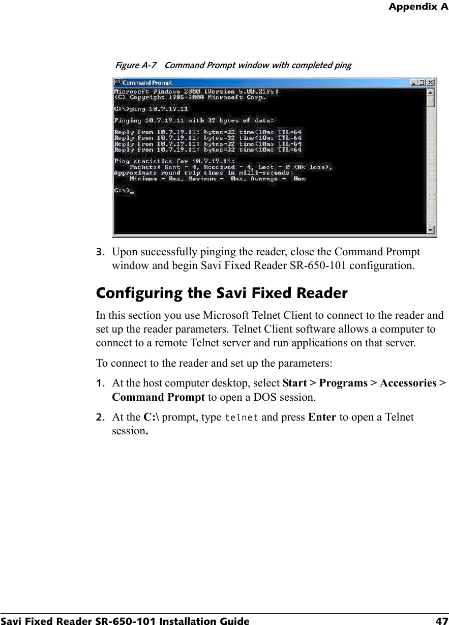
user manual pt 2
3.
user manual compliance statement
user manual pt 2
Navigation menu
Upload a User Manual
Namespaces
Wiki Guide
HTML
PDF
Info
Views
User Manual
Discussion / Help
Navigation