Savi Technology 650R-V2 RFID Tag Interrogator User Manual EchoPointSR650 101
Savi Technology Inc RFID Tag Interrogator EchoPointSR650 101
Contents
- 1. user manual pt 1
- 2. user manual pt 2
- 3. user manual compliance statement
user manual pt 2
CHAPTER 3
Managing the Reader Network
28 Savi Fixed Reader SR-650-101 Installation Guide
Identifying the Savi Fixed Reader
in SmartChain Site Manager
You must identify the reader in SmartChain Site Manager before you can
add and configure the reader. You can obtain the identification information
from the label on the reader.
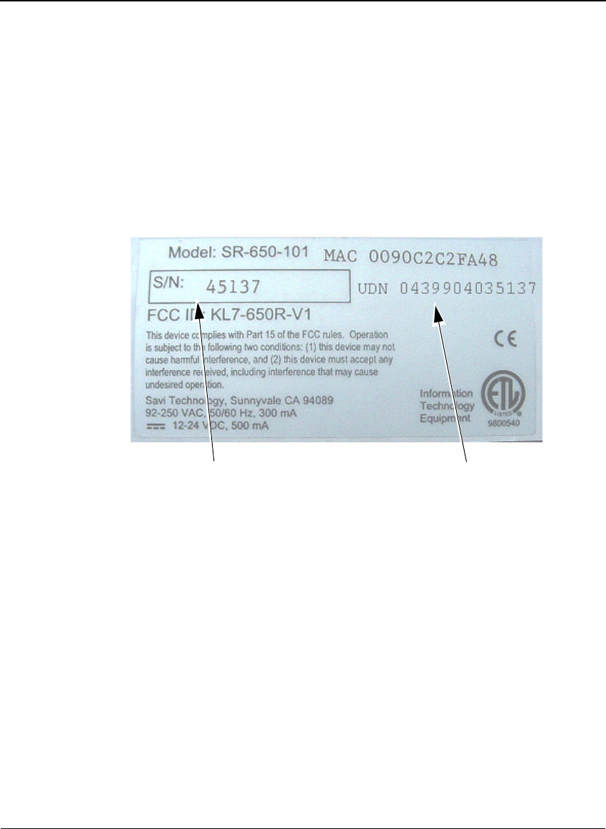
Figure 3-1 Label on the Savi Fixed Reader SR-650-101
For Ethernet networks, you use the unique device number (UDN) to
identify the reader. For SaviNet (RS-485) networks, you use the serial
number (also referred to as the SaviNet device number) to identify the
Savi Fixed Reader SR-650-101. You can also obtain the reader’s serial
number from the LED display when you apply power to the reader.
The first five digits of the UDN
are unique, followed by the
format of: YYMMNNNN. YY is
the year, MM is the month, and
NNNN is the last four digits of
the reader serial number
Reader serial number

Adding and Configuring the Reader in SmartChain Site Manager
Savi Fixed Reader SR-650-101 Installation Guide 29
Adding and Configuring the Reader
in SmartChain Site Manager
To add a device to the network, you can use auto-discovery or add a reader
manually. Whenever possible, Savi recommends using auto-discovery to
add a device.
Discovering a Reader Using an
Ethernet Connection
A Savi Fixed Reader SR-650-101 that is plugged into an Ethernet
broadcasts discovery packets. When you start a SmartChain Site Manager
that is connected to the Ethernet, it recognizes these broadcasts and
responds to the reader that a SmartChain Site Manager at a given IP address
is available for connection. The Savi Fixed Reader SR-650-101 must reside
on the same subnet mask as the SmartChain Site Manager to be managed
properly.
When a DHCP server is connected to the same network as the SmartChain
Site Manager and Savi Fixed Reader SR-650-101, the reader initiates a
DHCP operation to obtain a valid IP address to replace its default IP address
(10.7.19.11). If you are installing multiple readers, it is a good idea to
connect one reader to the network at a time to avoid IP address conflicts.
When a BOOTP domain server is connected to the same network as the
SmartChain Site Manager and Savi Fixed Reader SR-650-101, the BOOTP
server automatically assigns an IP address to the reader. The following four
parameters must be changed in SmartChain Site Manager to set up the
BOOTP server.

CHAPTER 3
Managing the Reader Network
30 Savi Fixed Reader SR-650-101 Installation Guide
To change the parameters for the BOOTP server:
1. Change the value of BootP from 0 to 1.
This activates the BOOTP server.
2. Obtain an IP address or group of IP addresses from your Network
Administrator to change the value(s) of the BootpIpAddress(es) for
your reader(s).
3. Set the subnet mask and gateway IP.
Name (Key) Type Range Default Description
Bootp Integer 0 or 1 0 Determines whether
BOOTP server is enabled
or not
0 = No
1 = Yes
BootpIpAddress String 0.0.0.0 Beginning IP address for
BOOTP IP address
assignments. The BOOTP
server begins assigning IP
addresses with this
address and increments
by one for each additional
address to be assigned
BootpSubnetMask String 255.255.128.0 Subnet mask to be
assigned to devices that
are also assigned an IP
address through the
BOOTP server
BootpGatewayIP String 0.0.0.0 IP address of the default
gateway to be assigned
to devices that are also
assigned an IP address
through the BOOTP
server

Adding and Configuring the Reader in SmartChain Site Manager
Savi Fixed Reader SR-650-101 Installation Guide 31
Discovering a Reader Using a
SaviNet Connection (RS-485)
If you are adding the reader to an RS-485 network where SmartChain
Site Manager is already running, you must force the discovery process.
1. On the Windows desktop, click the Site Manager Console icon.
2. In the Network area of the console, right-click a protocol and select
Discover All.
3. Select Refresh to see the new readers.
Note:
You can also initiate discovery from the Network Management
window. Click Network Management on the toolbar, right-click, and
select Discover All.
Note:
If you connect your RS-485 to RS-232 converter into a serial port
on SmartChain Site Manager that is not COM1, you must change the
value of the SaviNet\PortNumber parameter to the appropriate COM
port and then restart SmartChain Site Manager.
Adding a Reader Manually Using an
Ethernet Connection
You can manually add a Savi Fixed Reader SR-650-101 that is plugged into
an Ethernet by assigning a static IP address. SmartChain Site Manager must
have a TCP/IP subnet that is compatible with the reader’s default IP address
(10.7.19.11). The reader should be connected to SmartChain Site Manager
through a hub, switch, or cross-over cable.
1. On the Windows desktop, click the Site Manager Console icon.
2. In the Network area of the console, right-click a protocol and select
Add Device.
3. Fill in the device properties.

CHAPTER 3
Managing the Reader Network
32 Savi Fixed Reader SR-650-101 Installation Guide
Setting the Host IP and Synchronizing Time
You use the Network Manager to set the host IP and synchronize time
between the Savi Fixed Reader SR-650-101 and SmartChain Site Manager.
To set the host IP and time synchronization parameters:
1. On the desktop, click the Site Manager Console icon.
2. Click the Network Management button.
3. Select the device you want to configure.
4. Click Actions > Configure.
Note:
If the device was detected by auto-discovery, be sure to change the
local IP address.
Configuring the Reader with Savi Retriever Using a SaviNet Connection (RS-485)
Savi Fixed Reader SR-650-101 Installation Guide 33
Configuring the Reader with
Savi Retriever Using a SaviNet
Connection (RS-485)
A Savi Fixed Reader SR-650-101 that is connected to a Savi Retriever
through SaviNet connection (RS-485) requires updating the network.
Use the Network Menu commands to check or update the network.
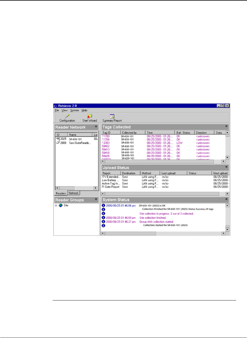
Figure 3-2 Savi Retriever main window
1. To open this window, right-click the icon of the host computer in the
Reader Network area.
2. Click Check Status to verify the computer status.
3. Click Verify Networks to verify the operation of the network.
4. Click Update Networks to find new readers and update the network.
The results of these commands appear in the System Status area.
Note:
The update network event happens automatically only when you
first install the system. After that, make sure you update the network
whenever you attach a new Savi Fixed Reader SR-650-101.

CHAPTER 3
Managing the Reader Network
34 Savi Fixed Reader SR-650-101 Installation Guide
Verifying Reader Communication
To confirm that a Savi Fixed Reader SR-650-101 is installed and
functioning correctly, you must verify that the reader can:
◆Communicate with the SmartChain Site Manager (verifies that
the reader is detected on the network)
◆Collect tags in the collection area
Once the Savi fixed reader is installed, refer to the Guide to SmartChain
Site Manager for information about testing the operation of the reader.

CHAPTER 4
Savi Fixed Reader SR-650-101 Installation Guide 35
Installing the Savi
Fixed Reader
4
Installing the Savi Fixed Reader SR-650-101 is a two-step process.
In sequential order, you must:
1. Position the reader to enable the most efficient communication range.
2. Mount the reader on the mounting bracket.
Positioning the Savi Fixed Reader
The Savi Fixed Reader SR-650-101 is designed to operate in a wide variety
of environments. The reader is housed in a rugged, weatherproof enclosure.
In ideal conditions (large, open, and unobstructed areas), the Savi Fixed
Reader SR-650-101 can collect tags up to 300 feet (91.44 meters) away.
However, a variety of factors can limit the Savi fixed reader collection
range, including:
◆Obstructions such as multiple walls, chained areas, solid-core doors,
and enclosures
◆RF interference from other equipment such as computers, walkie-talkies,
cellular phones, elevators, electrical motors, or other RF-emitting
devices
◆Savi Fixed Reader SR-650-101 mounting height of at least 20 feet
(6.1 meters)
◆Metal or RF-absorbent surface on the tracked item
◆Tag location relative to the Savi fixed reader, such as behind a metal
obstruction (as illustrated in Figure 4-1) or stacked under multiple layers
Some of these factors may be beyond your control. The goal when
positioning the Savi Fixed Reader SR-650-101 is to optimize advantages
and reduce limitations to make the collection range as efficient as possible.
CHAPTER 4
Installing the Savi Fixed Reader
36 Savi Fixed Reader SR-650-101 Installation Guide
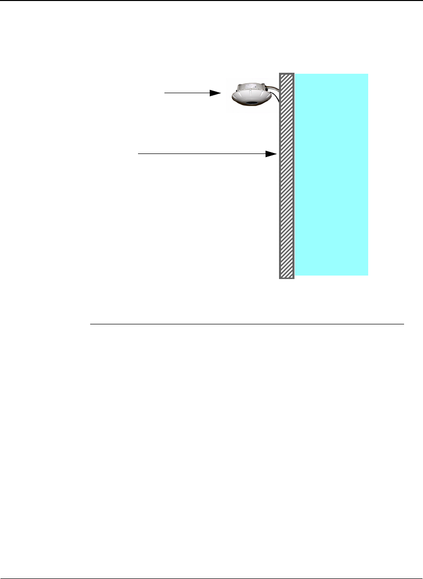
Figure 4-1 Impediment limiting the Savi Fixed Reader SR-650-101 collection range
If the location forces you to use a less-than-ideal position for the reader,
the collection range could be reduced, requiring additional readers.
Note:
If you must mount a Savi fixed reader on a wall, the collection range
may not extend to the opposite side of the wall. You may need a second
Savi fixed reader to monitor the area behind the wall.
The collection range of the equipment depends on surrounding obstructions
that may shield tags from receiving reader signals or cause reflections into
locations outside the line of sight. As a first step, it is best to identify reader
installation locations using a line of sight model to any assets equipped with
tags. You may need to experiment to cover the desired area.
To optimize performance:
◆Locate the reader at least 20 feet (6.1 meters) above the ground.
◆Avoid installations within 6 feet (2 meters) of metal surfaces, such as
temporary buildings or large steel doors.
Area of
limited
collection
ability
Metal wall
Savi fixed reader
mounted near a
ceiling

Mounting the Savi Fixed Reader
Savi Fixed Reader SR-650-101 Installation Guide 37
Caution:
The reader must be mounted in a horizontal plane with its dome
directed downward, as shown in Figure 4-1. Other orientations will distort
the field patterns and make performance unpredictable. Maintain the
horizontal orientation when using the wall mount kit, tripod, or other
mounting hardware.
Mounting the Savi Fixed Reader
You can mount the Savi Fixed Reader SR-650-101 using any of the
associated mounting hardware available from Savi Technology.
The mounting kit available from Savi Technology includes hardware to
mount a Savi fixed reader on a pole (wooden, metal, or concrete), I-beam,
wall, or a tripod. Refer to the instructions included with the mounting kit
for proper installation.
RFID hardware can be physically attached in any position or location.
If your installation requires a special attachment, Savi can develop and
manufacture a custom fixture.
If you have problems communicating with the Savi fixed reader during
or after the installation, refer to Chapter 5, “Reader Sustainment and
Maintenance,” for troubleshooting procedures.

CHAPTER 4
Installing the Savi Fixed Reader
38 Savi Fixed Reader SR-650-101 Installation Guide
CHAPTER 5
Savi Fixed Reader SR-650-101 Installation Guide 39
Reader Sustainment and
Maintenance
5
With minimal care, a Savi Fixed Reader SR-650-101 should perform
flawlessly. However, if a problem with a Savi fixed reader occurs, the
procedures in this chapter should help you solve it.
Warning:
Changes or modifications to the equipment that are not
expressly approved by Savi Technology could void the warranty and the
authority to operate the equipment.
Using the equipment in a manner not specified by the manufacturer might
impair the protection that the equipment provides.
Savi Technology is not responsible for radio/TV interference caused by
using unauthorized cable or by making unauthorized changes to this
equipment.
Repair and Maintenance
The DB-9 connector on the Savi Fixed Reader SR-650-101 provides
RS-232 serial access for Savi software maintenance tools that are used in
manufacturing or for diagnostic purposes. The RS-232 connection is not for
network connectivity.
To directly connect the Savi Fixed Reader SR-650-101 to the host computer
using the RS-232 port and a DB-9 serial cable:
1. Plug the cable’s female connector into the reader’s DB-9 input socket.
2. Connect the other end of the cable to a host computer.
CHAPTER 5
Reader Sustainment and Maintenance
40 Savi Fixed Reader SR-650-101 Installation Guide
Troubleshooting
The table in this section lists problems that could occur with the Savi Fixed
Reader SR-650-101 and potential solutions.
In the unlikely event that a Savi fixed reader fails or problems occur that
simple troubleshooting cannot solve, Savi Customer Support may
recommend that the reader be returned to Savi Technology.
Problem Solution
No power
(indicator light is not
blinking)
✦Confirm that power is available by checking circuit
breakers, power switches, or safety switches.
✦If AC-powered, verify the presence and voltage of
the power by connecting a test unit to the power
source. Check the AC fuses.
✦If DC-powered or solar powered, verify that the
external supply is supplying 12 to 24 VDC.
✦Verify that the power cable is securely plugged into
the power source and the Fixed Reader input.
✦Try a different power source.
✦Replace the power cable.
Network cables
damaged or
disconnected
✦Verify that the network cable is securely plugged
into the Fixed Reader.
✦Verify that the network cable is securely plugged
into the SR-650-101.
✦Check cables for physical damage.
ID needs confirmation ✦Reset the power (by disconnecting and then
reconnecting the live power source) to view the
Fixed Reader serial number, which flashes in
sequence after the reader is reset. See “Applying
Power to the Savi Fixed Reader” on page 25
✦Compare the Fixed Reader serial number to the
ID used in the management software and on the
printed label.
Unknown ✦Turn power off and then back on.
✦Call Savi Customer Support.

APPENDIX A
Savi Fixed Reader SR-650-101 Installation Guide 41
Using Telnet to Connect
to a Savi Fixed Reader
A
In this appendix, you configure your PC’s IP address and use Microsoft
Telnet client to connect the host computer to the Savi Fixed Reader
SR-650-101. Typically, you use SmartChain Site Manager auto-discovery
to connect to the reader.
Setting Up the Savi Fixed Reader
The Savi Fixed Reader SR-650-101 has an integrated network interface.
Note:
Note that if you connect multiple readers to the same network, they
will all have the same default IP address of 10.7.19.11 and may create
network conflicts.
Once the hardware is installed, you set the IP address for the Savi Fixed
Reader SR-650-101, ping the reader to verify its connection, and configure
the Savi Fixed Reader SR-650-101 parameters.
Configuring Your PC’s IP Address
To set up the proper IP addresses, you must first configure the host
computer to communicate with the Savi Fixed Reader SR-650-101.
To specify the IP address:
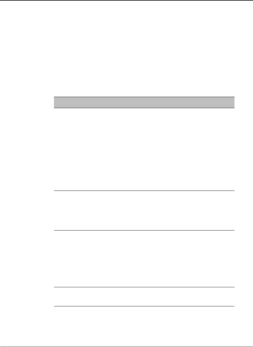
1. At the host computer desktop, select Start > Settings > Control Panel.
Appendix A
42 Savi Fixed Reader SR-650-101 Installation Guide
Figure A-1 Control Panel window
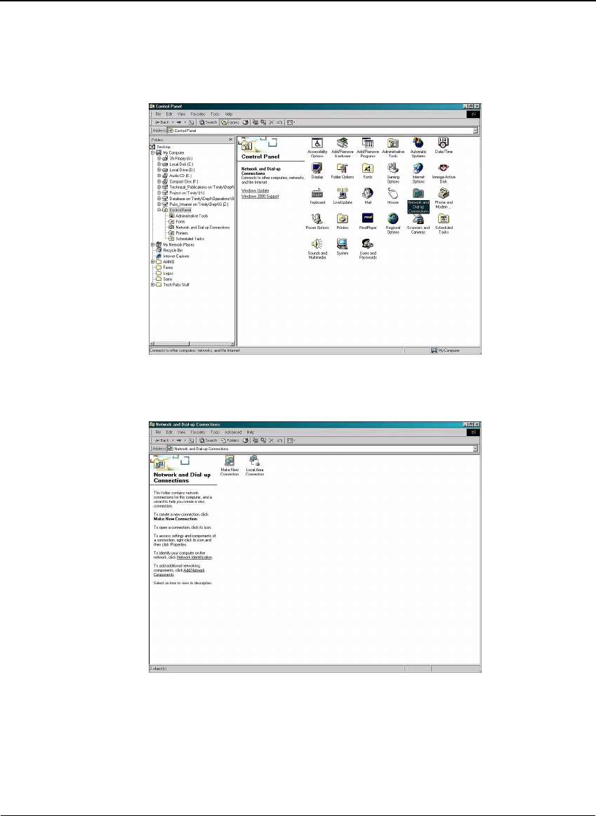
2. Double-click the Network and Dial-Up Connections icon.
Figure A-2 Network and Dial-Up Connections window
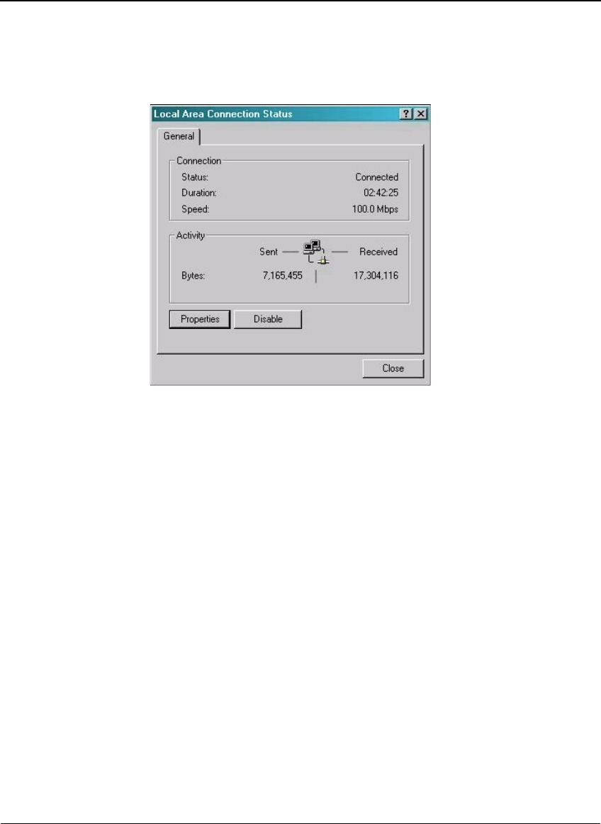
3. Double-click the Local Area Connection icon.
Appendix A
Savi Fixed Reader SR-650-101 Installation Guide 43
Figure A-3 Local Area Connection Status window
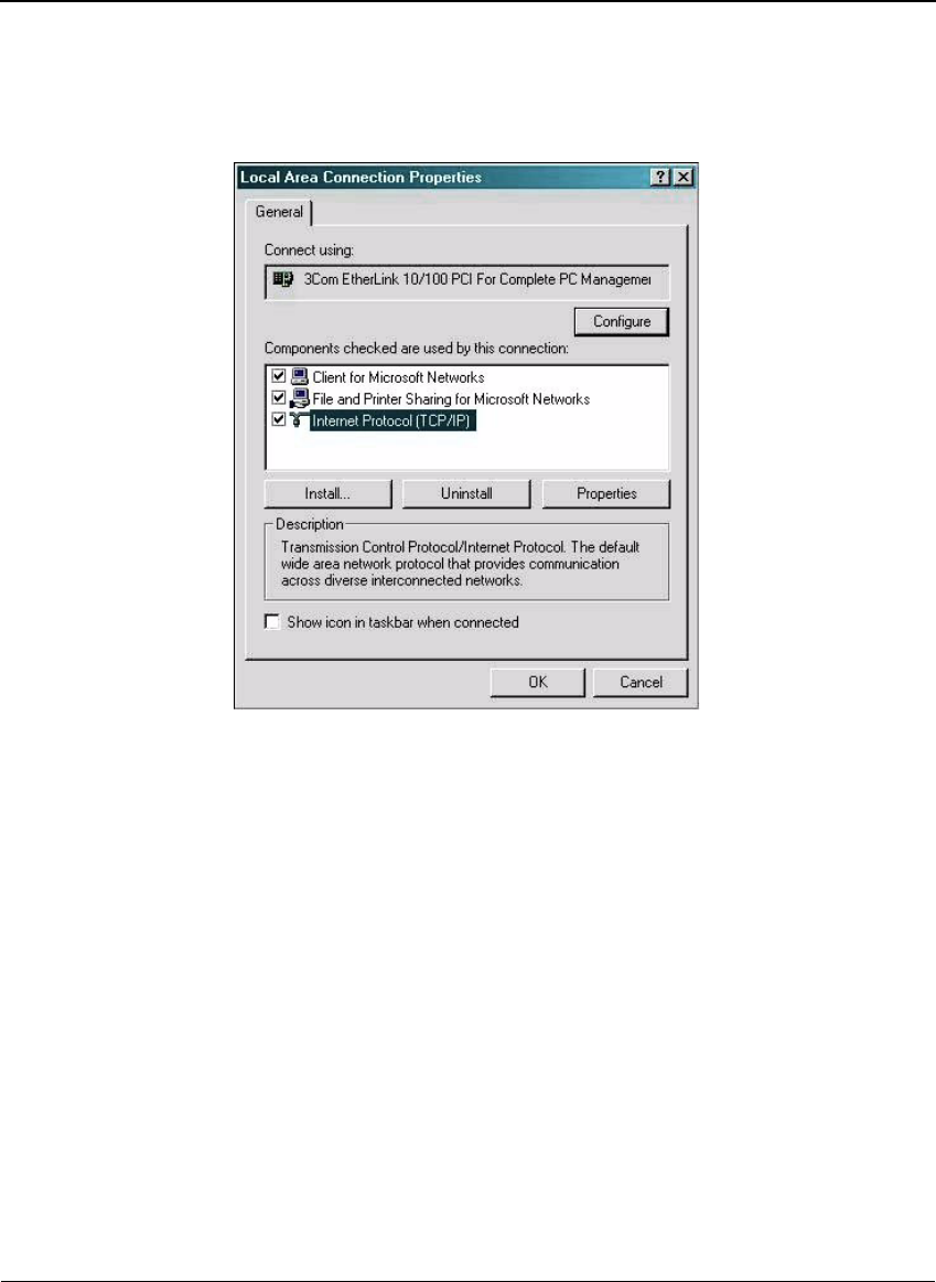
4. Click Properties.
Appendix A
44 Savi Fixed Reader SR-650-101 Installation Guide
Figure A-4 Local Area Connection Properties window
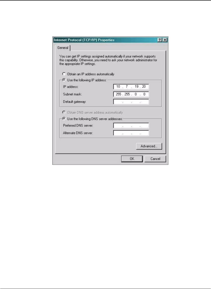
5. Double-click Internet Protocol (TCP/IP).
Appendix A
Savi Fixed Reader SR-650-101 Installation Guide 45
Figure A-5 Internet Protocol TCP/IP Properties window
6. Make the necessary changes to the IP address and Subnet mask
addresses and click OK.
The default IP address for the Savi Fixed Reader SR-650-101 is
10.7.19.11. You can set the host IP address to 10.7.19.20, the
Subnet mask to 255.255.0.0, and leave all others blank.
7. Close all windows and return to the desktop.
Appendix A
46 Savi Fixed Reader SR-650-101 Installation Guide
Pinging the Savi Fixed Reader
You need to check the network connection from your computer to the
Savi Fixed Reader SR-650-101. You can either use an Ethernet cross
connect cable from your PC’s Ethernet port to the Ethernet cable from
the Savi Fixed Reader SR-650-101 (with a coupler) or connect both your
PC and the Savi Fixed Reader SR-650-101 to a live local area network.
You use the command prompt to ping the reader.
To ping the reader:
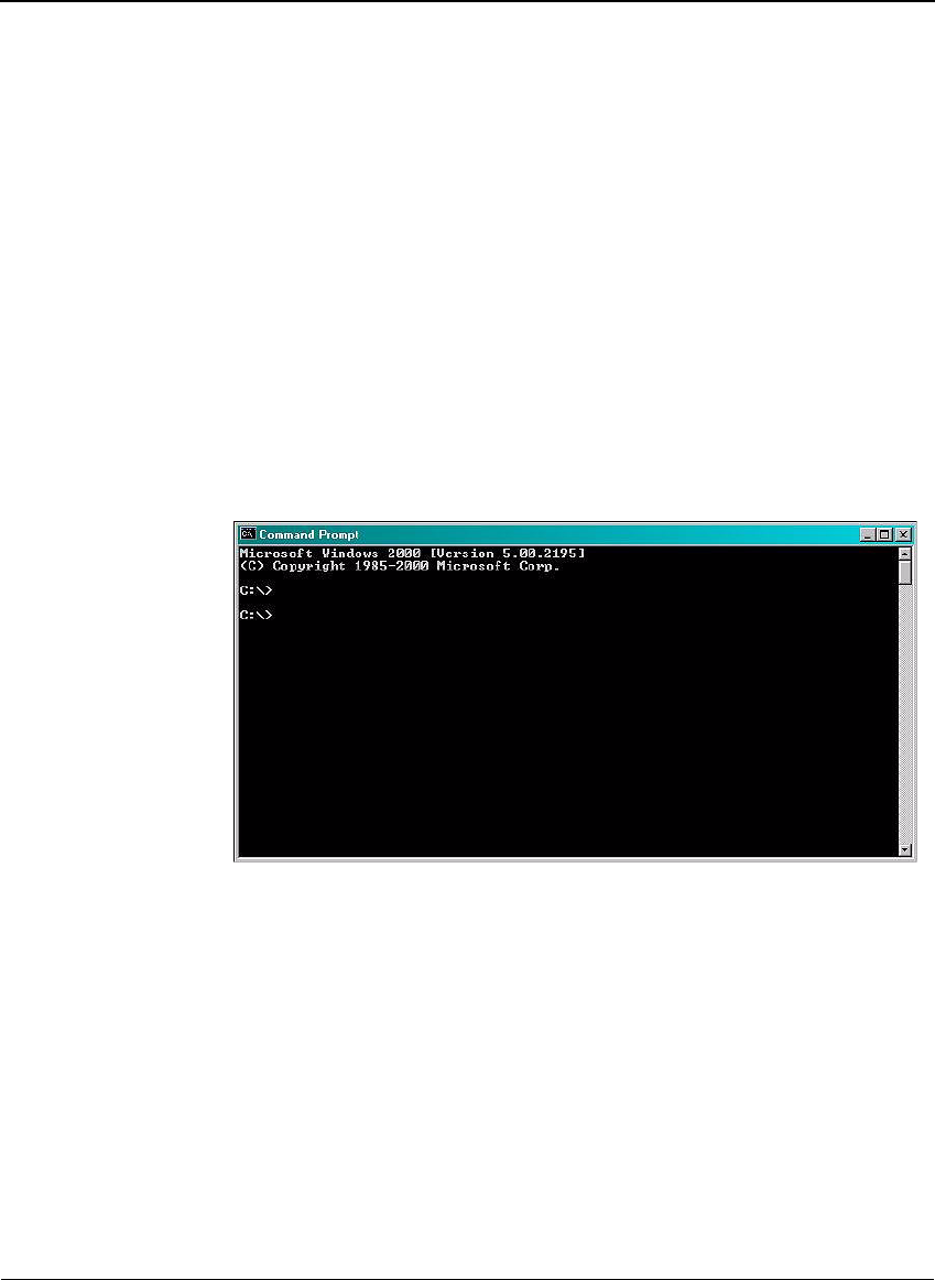
1. At the host computer desktop, select Start > Programs > Accessories >
Command Prompt to open a DOS session.
Figure A-6 Command Prompt window
2. Type ping 10.7.19.11 (this is the default IP address of the reader) and
press Enter.
Pinging proceeds until it completes all cycles.
Appendix A
Savi Fixed Reader SR-650-101 Installation Guide 47
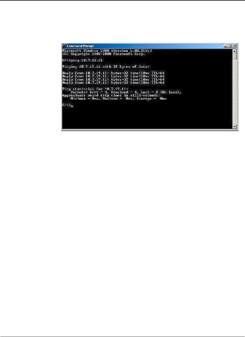
Figure A-7 Command Prompt window with completed ping
3. Upon successfully pinging the reader, close the Command Prompt
window and begin Savi Fixed Reader SR-650-101 configuration.
Configuring the Savi Fixed Reader
In this section you use Microsoft Telnet Client to connect to the reader and
set up the reader parameters. Telnet Client software allows a computer to
connect to a remote Telnet server and run applications on that server.
To connect to the reader and set up the parameters:
1. At the host computer desktop, select Start > Programs > Accessories >
Command Prompt to open a DOS session.
2. At the C:\ prompt, type telnet and press Enter to open a Telnet
session.
Appendix A
48 Savi Fixed Reader SR-650-101 Installation Guide
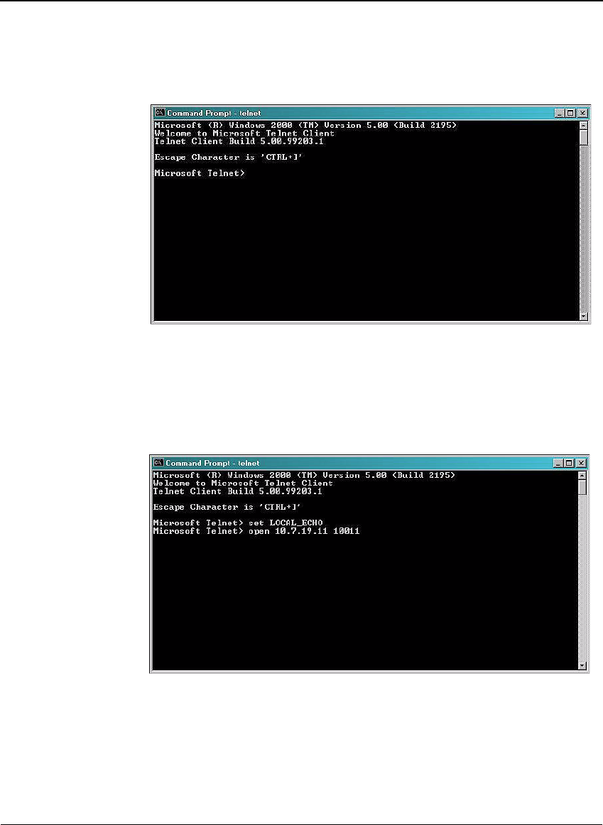
Figure A-8 Telnet Client window
3. At the first prompt, type set LOCAL_ECHO and press Enter to enable the
echo so you can verify key entries.
4. At the second prompt, type open 10.7.19.11 10011 (this is the
CADTP port number) and press Enter to connect to the reader.
Figure A-9 Telnet connection commands
You see a blank Command Prompt - telnet window if the telnet
connection is successful.
Now you can run commands to modify the properties of the reader.
Appendix A
Savi Fixed Reader SR-650-101 Installation Guide 49
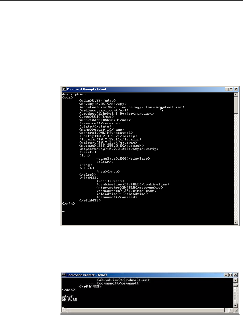
To view existing reader properties:
1. At the cursor, type description and press Enter.
The current properties of the reader appear. Not all properties can be
modified.
Figure A-10 Description of reader properties
2. At the cursor, type udap? and press Enter to display the UDAP
firmware’s value.
The property udap is a read-only property; you cannot modify it.
Figure A-11 Telnet UDAP value display
Appendix A
50 Savi Fixed Reader SR-650-101 Installation Guide
3. Type rssi? and press Enter to display the reader’s residual signal
strength indicator values.
4. Type diags and press Enter to record the MAC address, temperature,
and battery voltage.
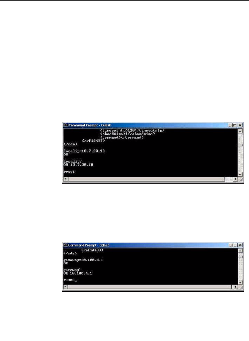
To assign a new local IP address to the reader and modify gateway and
netmask addresses:
1. At the cursor, type localip=10.7.20.118 (or whatever valid IP address
you want to assign) and press Enter to set the reader IP address.
Figure A-12 Telnet local IP address display
2. Type reset and press Enter to cause the IP address to take effect.
Now you can use Telnet to connect to the reader at the new IP address.
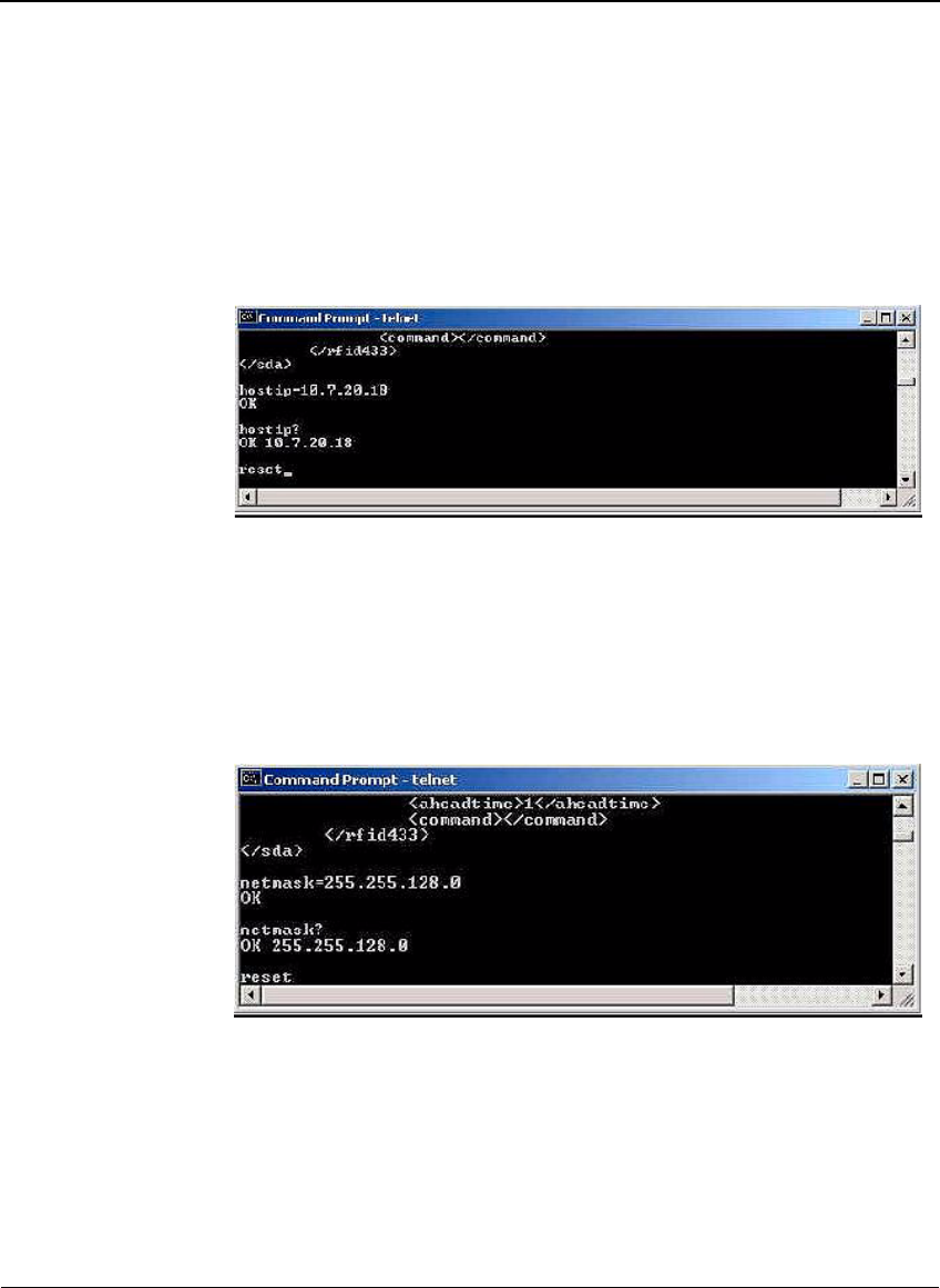
3. Type gateway=10.100.4.1 (or whatever valid IP address you want to
assign) and press Enter to set the reader gateway IP address.
Figure A-13 Telnet Gateway IP address display
4. Type reset and press Enter to make the gateway IP address take effect.
Appendix A
Savi Fixed Reader SR-650-101 Installation Guide 51
5. Type hostip=10.7.20.18 (or whatever valid IP address you want to
assign to the SmartChain Site Manager) and press Enter to set the
reader host IP address. This will point the Savi Fixed Reader SR-650-
101 to the SmartChain Site Manager’s IP address.
Figure A-14 Telnet Host IP address display
6. Type reset and press Enter to apply the host IP address.
The host is the computer to which the reader sends the event data.
7. Type netmask=255.255.128.0 (or whatever valid mask you want to
assign) and press Enter to set the reader network mask as depicted in
Figure A-15.
Figure A-15 Telnet network mask display
8. Type reset and press Enter to make the netmask take effect.
9. Type ntpserverip=10.7.20.18 (or whatever valid NTP address you
want to assign) and press Enter to set the NTP server IP address that the
reader will listen to.
Appendix A
52 Savi Fixed Reader SR-650-101 Installation Guide
Figure A-16 Telnet NTP server IP address display
To set reader parameters:
1. Type combinetime=ENABLE (or type combinetime=DISABLE), and press
Enter to enable (or disable) the time of event data from the reader to
combine with the time of the tag received from the Signpost.
Figure A-17 Telnet combine time command
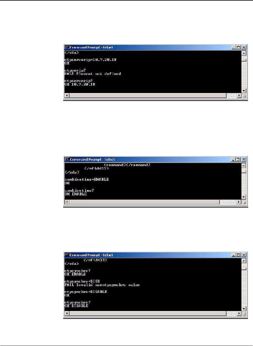
2. Type ntpsynchro=ENABLE (or type ntpsynchro=DISABLE), and press
Enter to enable (or disable) the reader time and date to synchronize with
the NTP server.
Figure A-18 Telnet NTP server synchronization command
Appendix A
Savi Fixed Reader SR-650-101 Installation Guide 53
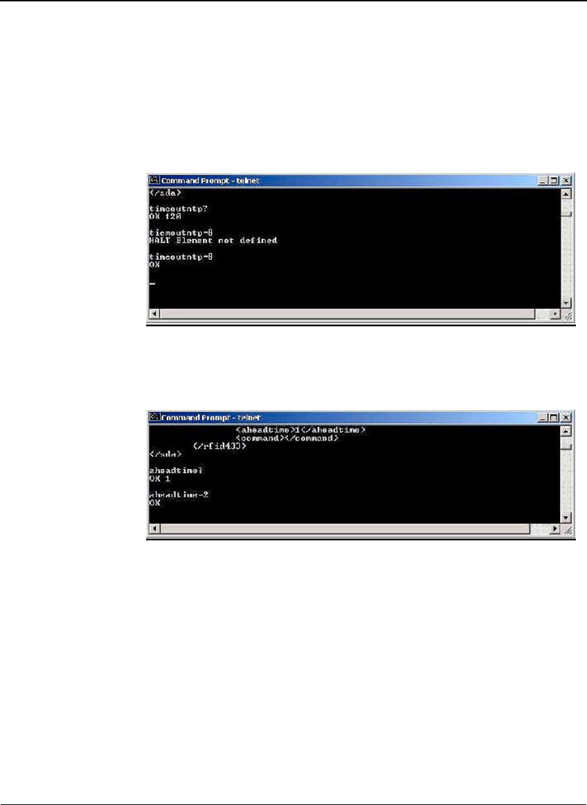
3. Type timeoutntp=8 (unit: minutes) and press Enter to set the period
(in minutes) for which, if the reader has not received time information,
it will assume it has lost time synchronization with the NTP server.
Figure A-19 Telnet NTP server time out command
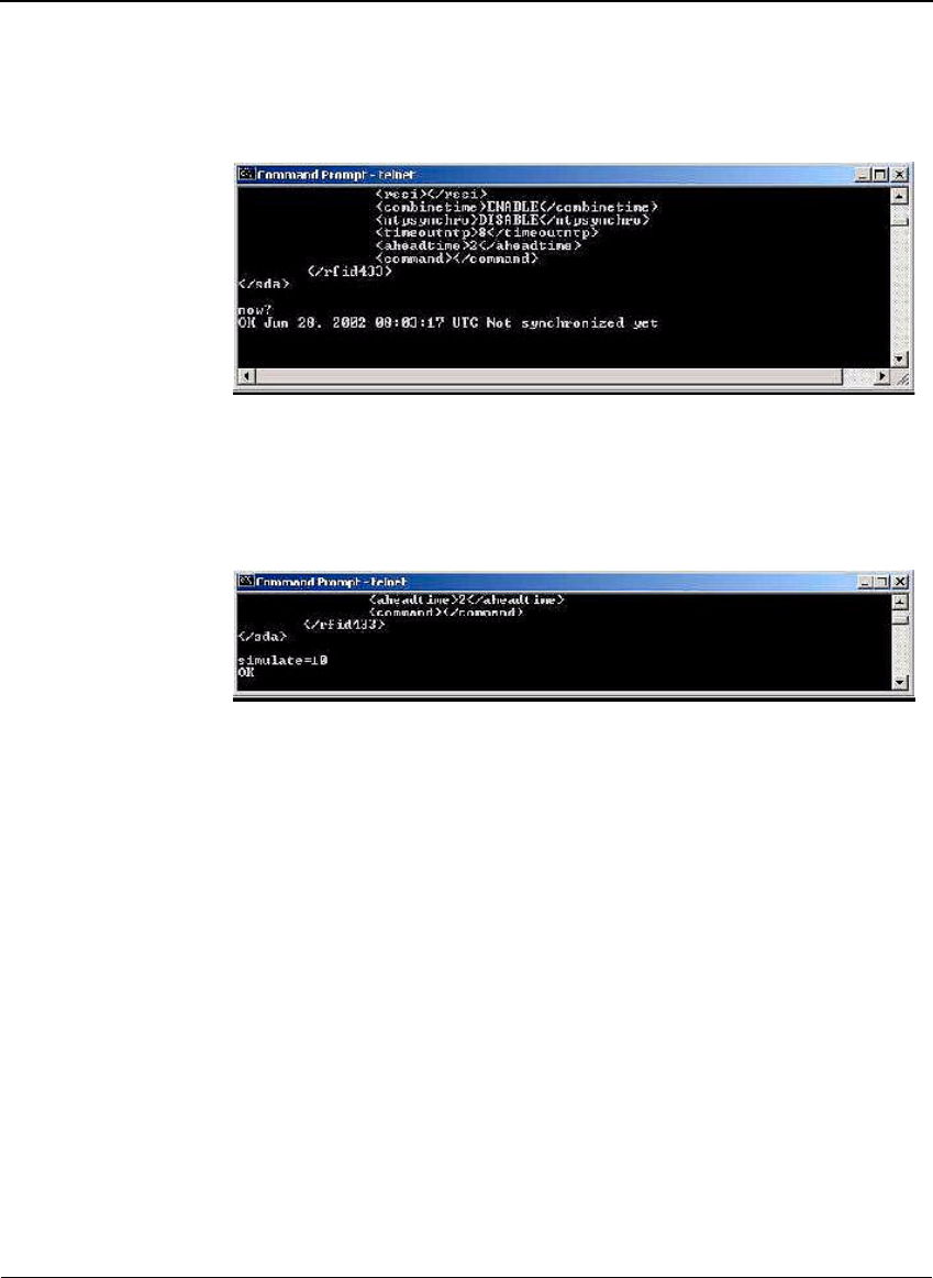
4. Type aheadtime=2 (unit: seconds) and press Enter to set the time
(in seconds) of the reader ahead of the synchronized NTP server time.
Figure A-20 Telnet reader ahead time command
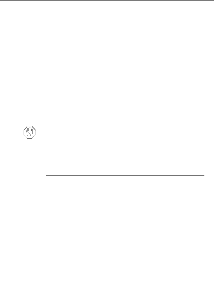
5. Type now? and press Enter to display the current time.
If the reader is not set to synchronize with an NTP server, then you can
also set the time with this command.
Appendix A
54 Savi Fixed Reader SR-650-101 Installation Guide
Figure A-21 Telnet time command
6. Type simulate=10 and press Enter to generate 10 simulated events.
If you have a daemon listening to the event on the host computer, it will
receive the events.
Figure A-22 Telnet simulate command
7. Type reset and press Enter to reset the Savi Fixed Reader SR-650-101
with all the new parameters.
APPENDIX B
Savi Fixed Reader SR-650-101 Installation Guide 55
Installing and Removing
Heat Shrink Tubing
B
Although Savi products are rated for use in severe environments, power and
network connectors on Savi Readers and RF links that are subject to
repeated installation and removal can erode. Savi recommends using heat
shrink tubing to minimize deterioration. Follow these steps to safely install
and remove heat shrink tubing to protect cables and connectors from rain
and harsh weather conditions.
Warning:
Installing heat shrink tubing requires using a hair dryer with
nozzle temperatures in excess of 257°F (125°C). Exercise care during
installation to prevent serious burns.
Removing heat shrink tubing requires using an object with a sharp edge,
such as a box cutter or pocketknife. Handle the sharp object with care to
prevent potential cuts.
Caution:
When installing heat shrink tubing, connectors can be damaged
under temperatures in excess of 500°F (260°C). Use the lowest heat
setting possible; the minimum temperature at which the heat shrink
tubing will contract is 257°F (125°C). Use hair dryers with small nozzles
and aim the direct air flow to the heat shrink only.
When removing heat shrink tubing, take notice to not cut too deeply as
cutting the cable or damaging the connector will require replacing the
entire cord assembly.

Appendix B
56 Savi Fixed Reader SR-650-101 Installation Guide
Installing Heat Shrink Tubing
1. Place the heat shrink over the cable, and then mate the connectors.
The connectors are fully mated when the detent is engaged.
2. Position the heat shrink tubing so it is not completely against the
reader’s connector panel and covering the entire connector shell but is
.25 of an inch (6.35 mm) from the connector panel.
3. Use a hair dryer to shrink the heat shrink tubing.
Heat shrink tubing conforms to the connector shell when fully shrunk.
Removing Heat Shrink Tubing
1. Disconnect power from the unit prior to removing heat shrink tubing.
The heat shrink tubing must be at room temperature before removal.
2. Using a box cutter or pocketknife, carefully score the heat shrink tubing
along its full length. Score the heat shrink tubing only deep enough to
peel the tubing off the cable.
3. Lift a scored corner and peel back the heat shrink tubing. Use a small
pair of long-nosed pliers for assistance, if necessary.