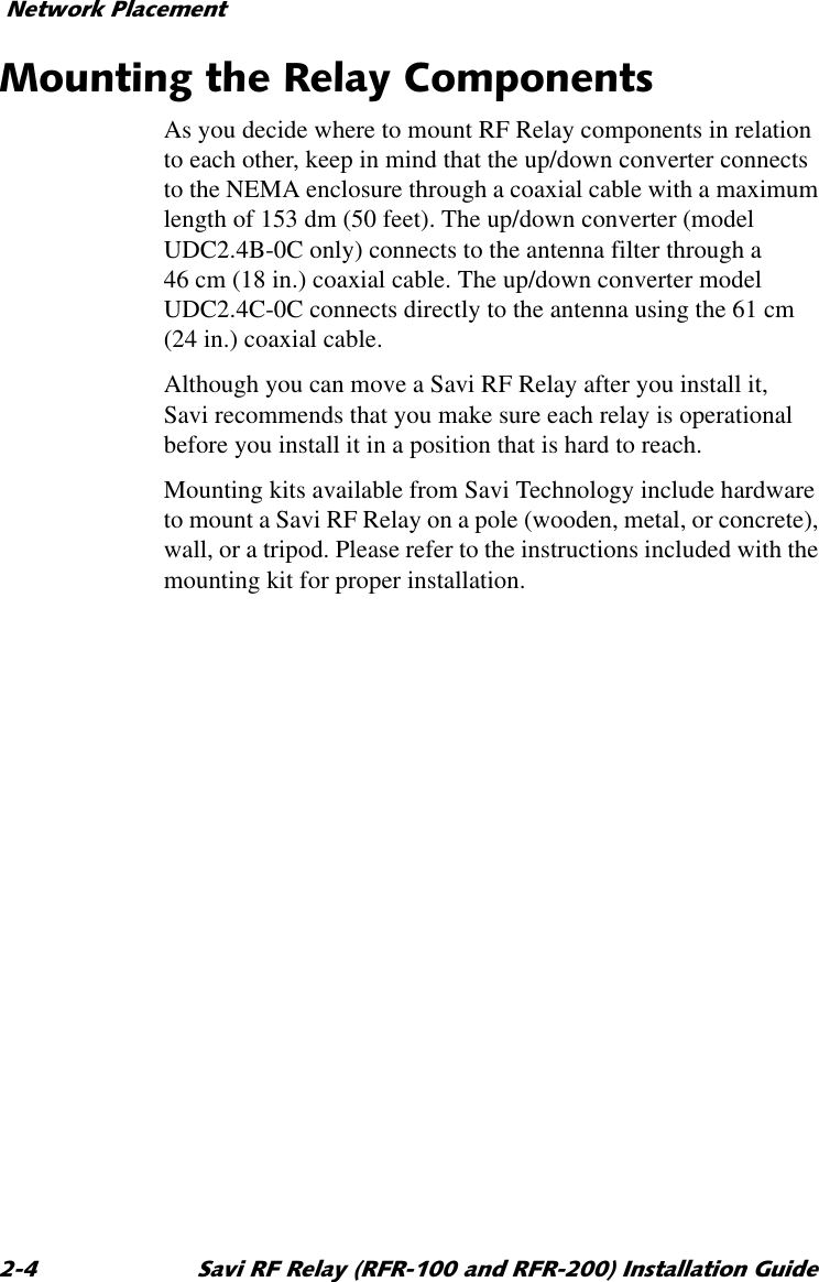
Savi Technology RELAY-V2 2.4GHz UP/Down Converter User Manual
Savi Technology Inc 2.4GHz UP/Down Converter
UserManual.wiki
>
Savi Technology
>
RELAY V2 User Manual
User Manual
Navigation menu
Upload a User Manual
Namespaces
Wiki Guide
HTML
PDF
Info
Views
User Manual
Discussion / Help
Navigation


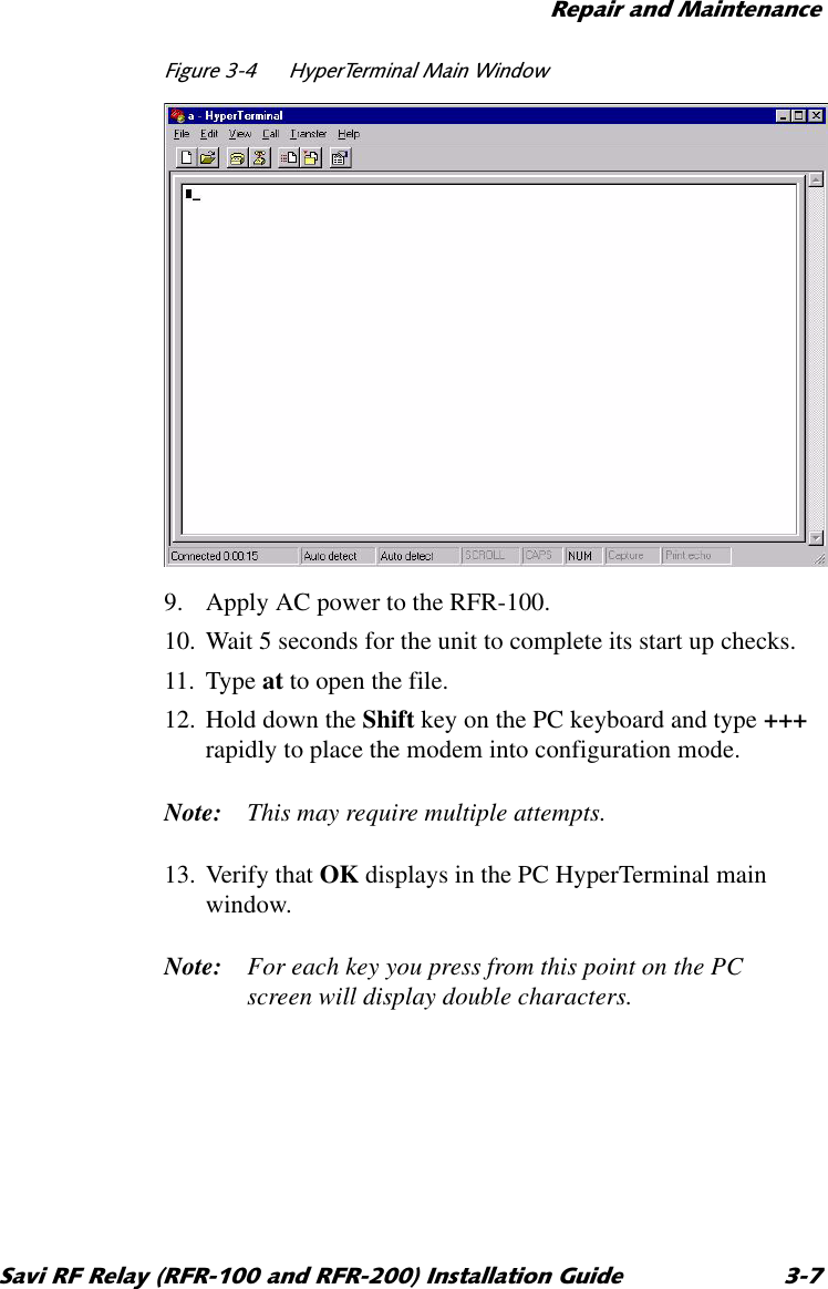
![5HSDLUDQG0DLQWHQDQFH 6DYL5)5HOD\5)5DQG5)5,QVWDOODWLRQ*XLGH14. From the range of 10 to 250 (the factory setting is CH 100), determine the channel to use. The new channel should be at least twenty channels from the factory setting in order to prevent interference.15. Type ATS61=[insert new channel number] and press Enter to set the new transmit channel.16. Type ATS62=[insert new channel number] and press Enter to set the new receive channel.17. Type AT&V1 and press Enter to display the S Register settings on the screen.18. Verify that S Registers 61 and 62 are set to the channel that you selected in Step 14. If not, repeat Steps 15 through 17.19. Type AT&W to store the new configuration.20. Remove the RS-485 adapter cable.21. Disconnect and reconnect the power to the RFR-100 to return it to data mode.](https://usermanual.wiki/Savi-Technology/RELAY-V2/User-Guide-153727-Page-32.png)
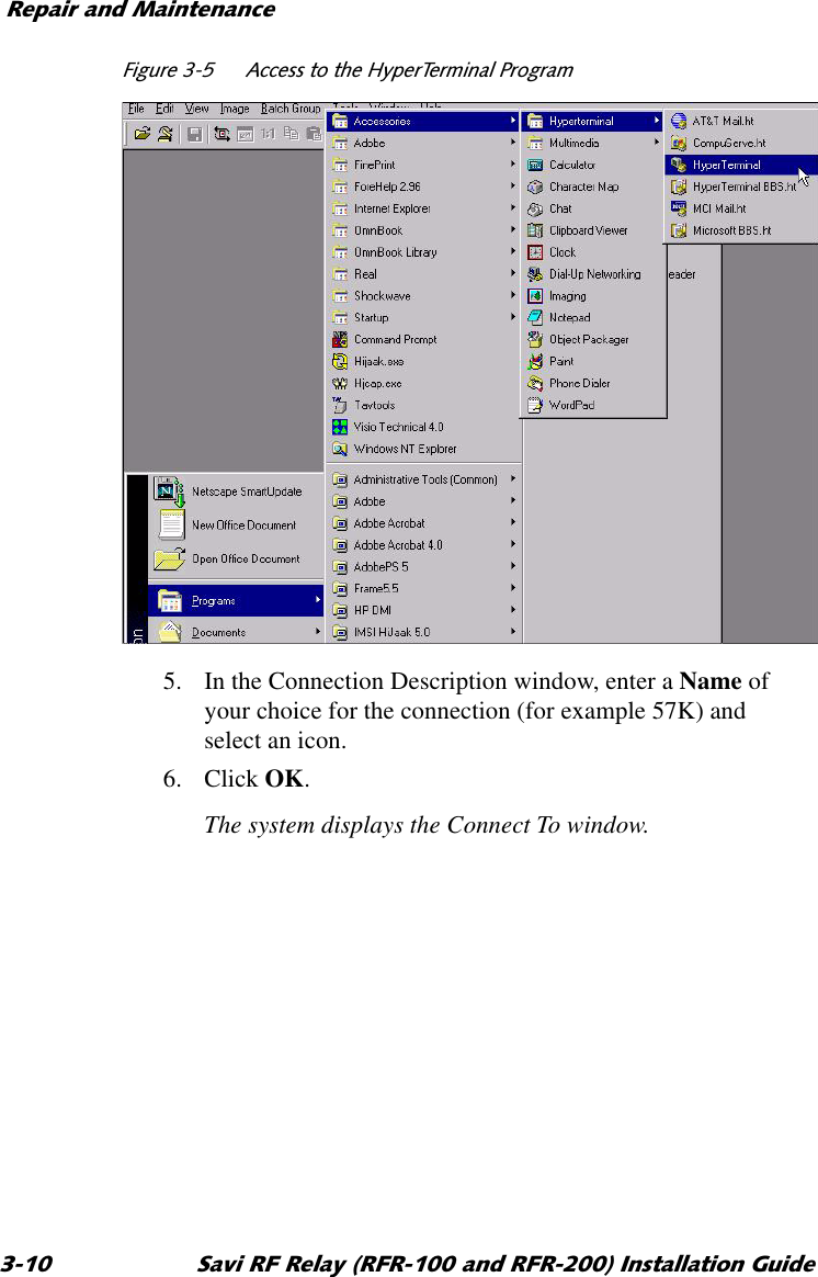


![5HSDLUDQG0DLQWHQDQFH 6DYL5)5HOD\5)5DQG5)5,QVWDOODWLRQ*XLGH19. From the range of 10 to 250 (factory setting is CH 100), determine the channel to use.The new channel should be at least twenty channels from the factory setting in order to prevent interference.20. Type ATS61=[insert new channel number] and press Enter to set the new transmit channel.21. Type ATS62=[insert new channel number] and press Enter to set the new receive channel.22. Type AT&V1 and press Enter to display the S Register settings on the screen.23. Verify that S Registers 61 and 62 are set to the channel that you selected in Step 19. If not, repeat Steps 20 through 22.24. Type AT&W to store the new configuration.25. Remove the RS-232 cable from the RF Modem and replace the RS-232 cable from the LonWorks module.26. Disconnect and reconnect the power to the RFR-200 to return it to data mode.27. Close the cover to the RF Relay and secure it shut.](https://usermanual.wiki/Savi-Technology/RELAY-V2/User-Guide-153727-Page-38.png)