Savi Technology RELAY-V2 2.4GHz UP/Down Converter User Manual
Savi Technology Inc 2.4GHz UP/Down Converter
User Manual

6DYL5)5HOD\
5)5DQG5)5
,QVWDOODWLRQ*XLGH
9HUVLRQ
LL 6DYL5)5HOD\5)5DQG5)5,QVWDOODWLRQ*XLGH
First edition (November 1997)
Order number DOC-2008
Part number 805-01709-001 Rev. G
Copyright © 2001 Savi Technology, Inc. All rights reserved. Printed in the United States of
America.
Information in this manual is subject to change without notice and does not represent a commitment
from the vendor. The software and/or databases described in this document are furnished under a
license agreement or nondisclosure agreement. The software and/or databases may be used or copied
only in accordance with the terms of the agreement. It is against the law to copy the software on any
medium except as specifically allowed in the license or nondisclosure agreement.
Savi, Batch Collection, and TyTag are registered trademarks and Adaptive Routing, Enhanced Batch
Collection, Hand Held Interrogator (HHI), Savi Asset Manager, Savi Fixed Interrogator,
Savi GateReader, Savi Mobile Manager, Savi MobileReader, Savi Retriever, Savi SDK, Savi
SmartChain, Savi System, Savi Tools, SaviReader, SaviTag, and SealTag are trademarks of Savi
Technology, Inc.
Other product names mentioned in this guide may be trademarks or registered trademarks of their
respective owners and are hereby acknowledged.
This manual was produced by the Savi Technology Publications Group. Please address any
comments or requests for updates to:
Savi Technology, Inc.
Publications Manager
615 Tasman Drive
Sunnyvale, CA 94089-1707
Phone: 1-408-743-8000
Facsimile 1-408-543-8650
Web Site: http: //www.savi.com
Author: Marlowe Conde
Contributors: Eugene Schlindwein
Layout Design and Production: Marlowe Conde

6DYL5)5HOD\5)5DQG5)5,QVWDOODWLRQ*XLGH LLL
5HJXODWRU\$SSURYDOV
)HGHUDO&RPPXQLFDWLRQV&RPPLVVLRQ
)&&1RWLFH
The Federal Communications Commission has established technical standards regarding radio
frequency energy emitted by computer devices. This equipment has been tested and found to comply
with the limits for a Class A digital device, pursuant to Part 15 of the FCC Rules. These limits are
designed to provide reasonable protection against harmful interference when the equipment is
operated in a commercial environment. This equipment generates, uses, and can radiate radio
frequency energy and, if not installed and used in accordance with the instruction manual, may cause
harmful interference with radio/TV reception. Operation of this equipment in a residential area is
likely to cause harmful interference in which case the user will be required to correct the interference
at his own expense.
Changes or modifications to this equipment that are not expressly approved by
Savi Technology could void the warranty and the authority to operate this
equipment.
Savi Technology is not responsible for radio/TV interference caused by using
unauthorized cable or by making unauthorized changes to this equipment.
3URGXFW6DIHW\
The RFR-100 and RFR-200 are ETL listed (UL 1950).
LY 6DYL5)5HOD\5)5DQG5)5,QVWDOODWLRQ*XLGH
&RQYHQWLRQVLQWKLV*XLGH
The following table explains guide conventions and typography usage.
*XLGH&RQYHQWLRQV
Example Meaning and Use
Note: Notes call attention to facts or advice that deserve
special attention.
Caution notices call attention to the possibility of
damaging the product, the system, or your work
(for example, potential loss of data).
Warning notices call attention to the possibility
of injury to people.
Examples provide a scenario to further explain
the preceding direction or procedure.
7HUPLQDO/RFNHG Bold type is used for prompts, field names, and other
text as displayed on the screen.
$?,167$// Bold type is also used for text you enter exactly as
shown.
'$7$ Monospaced type is used for system messages, examples
of data files, program code, and other text where column
alignment is important.
name.bmp or tag_id Italic type is used for emphasis of a word or phrase that
is new or especially important.
&WUO + =Used for a keyboard control codes or manual keystrokes.
This example tells you to hold the &WUO key while you
press the =key.
Example
7DEOHRI&RQWHQWV
6DYL5)5HOD\5)5DQG5)5,QVWDOODWLRQ*XLGH Y
Regulatory Approvals . . . . . . . . . . . . . . . . . . . . . . . . . . . . . . . iii
Federal Communications Commission (FCC) Notice . . . iii
Product Safety . . . . . . . . . . . . . . . . . . . . . . . . . . . . . . . . . iii
Conventions in this Guide. . . . . . . . . . . . . . . . . . . . . . . . . . . . iv
Chapter 1: Overview
The RF Relay . . . . . . . . . . . . . . . . . . . . . . . . . . . . . . . . . . . . 1-2
RF Relay Specifications . . . . . . . . . . . . . . . . . . . . . . . . . . . . 1-4
Chapter 2: Installation
Network Placement. . . . . . . . . . . . . . . . . . . . . . . . . . . . . . . . 2-2
Mounting the Relay Components. . . . . . . . . . . . . . . . . . 2-4
Physical Connections . . . . . . . . . . . . . . . . . . . . . . . . . . . . . . 2-6
Attaching the Filter to the Antenna . . . . . . . . . . . . . . . . 2-6
Interconnecting the Relay Components . . . . . . . . . . . . . 2-7
Connecting the Power Cable . . . . . . . . . . . . . . . . . . . . . 2-9
Connecting the Network Cable(s) . . . . . . . . . . . . . . . . 2-10
Verification . . . . . . . . . . . . . . . . . . . . . . . . . . . . . . . . . . . . . 2-11
Chapter 3: Maintenance
Repair and Maintenance . . . . . . . . . . . . . . . . . . . . . . . . . . . . 3-2
Replacing the Fuse . . . . . . . . . . . . . . . . . . . . . . . . . . . . . 3-2
Changing Channels. . . . . . . . . . . . . . . . . . . . . . . . . . . . . 3-3
Troubleshooting . . . . . . . . . . . . . . . . . . . . . . . . . . . . . . . . . 3-18
Getting Assistance. . . . . . . . . . . . . . . . . . . . . . . . . . . . . . . . 3-19
Technical Support. . . . . . . . . . . . . . . . . . . . . . . . . . . . . 3-19
6DYL5)5HOD\5)5DQG5)5,QVWDOODWLRQ*XLGH YLL
/LVWRI)LJXUHV
)LJXUH 3DJH
1-1 Savi RF Relay Components . . . . . . . . . . . . . . . . . . . . . . . . . . . . . . 1-3
2-1 Two RF Relays Linking a Computer with a Wired Network. . . . . 2-2
2-2 Savi RF Relays Linking Two SaviReader Wired Networks. . . . . . 2-3
2-3 Mounted Antenna with Model UDC2.4C-0C Converter . . . . . . . . 2-5
2-4 Mounting the Antenna with Filter . . . . . . . . . . . . . . . . . . . . . . . . . 2-7
2-5 RF Relay, Bottom View . . . . . . . . . . . . . . . . . . . . . . . . . . . . . . . . . 2-8
3-1 Access to the HyperTerminal Program. . . . . . . . . . . . . . . . . . . . . . 3-4
3-2 HyperTerminal Connect To Window . . . . . . . . . . . . . . . . . . . . . . . 3-5
3-3 HyperTerminal COM Properties Window . . . . . . . . . . . . . . . . . . . 3-6
3-4 HyperTerminal Main Window . . . . . . . . . . . . . . . . . . . . . . . . . . . . 3-7
3-5 Access to the HyperTerminal Program. . . . . . . . . . . . . . . . . . . . . 3-10
3-6 HyperTerminal Connect To Window . . . . . . . . . . . . . . . . . . . . . . 3-11
3-7 HyperTerminal COM Properties Window . . . . . . . . . . . . . . . . . . 3-12
3-8 HyperTerminal Main Window . . . . . . . . . . . . . . . . . . . . . . . . . . . 3-13

6DYL5)5HOD\5)5DQG5)5,QVWDOODWLRQ*XLGH
2YHUYLHZ 1
This manual describes how to install both the Savi RF Relay model
100 (RFR-100) and the Savi RF Relay model 200 (RFR-200). Both
models provide wireless links among readers or between readers
and a host computer. The RFR-100 connects to RS-485 networks,
while the RFR-200 connects to LonWorks® networks.
7KH5)5HOD\
6DYL5)5HOD\5)5DQG5)5,QVWDOODWLRQ*XLGH
7KH5)5HOD\
In situations where wired connection is impractical between a
host computer and a network of SaviReaders (or between two
sub-networks of SaviReaders), two Savi RF Relays can create a
wireless connection. This connection allows one host computer
to control readers that monitor a much larger physical area than
is possible using only wired connections.
The Savi RF Relay is available in two models, both of which are
described in this manual:
•The RFR-100 model provides a long-distance wireless link
in an RS-485 network, using an RF modem.
•The RFR-200 model provides a long-distance wireless link
in a LonWorks network, using an RF modem.
Both models of the Savi RF Relay have four basic components:
•The RF Relay itself, which includes a wireless transceiver
and network interface in a weatherproof NEMA enclosure
•An up/down converter (two models), which provides
necessary frequency conversion between the RF Relay and
the antenna
•A bandpass filter that attaches to the end of the antenna
(up/down converter model UDC2.4B-0C only)
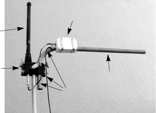
•An omnidirectional 2.4 GHz antenna
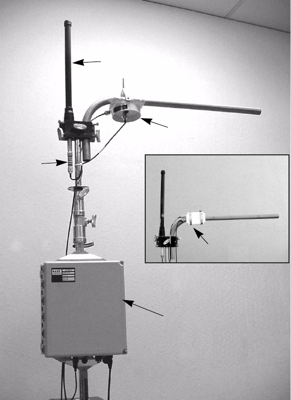
Figure 1-1 shows a Savi RF Relay with its antenna and up/down
converter mounted on the same mast.
7KH5)5HOD\
6DYL5)5HOD\5)5DQG5)5,QVWDOODWLRQ*XLGH
)LJXUH 6DYL5)5HOD\&RPSRQHQWV
Antenna
Up/down
RF Relay
Converter
in NEMA case
Filter
(Model UDC2.4B-0C)
Up/down
Converter
(Model UDC2.4C-0C)

5)5HOD\6SHFLILFDWLRQV
6DYL5)5HOD\5)5DQG5)5,QVWDOODWLRQ*XLGH
5)5HOD\6SHFLILFDWLRQV
The Savi RF Relay is designed for indoor or outdoor use.
Table 1-2 describes its specifications.
7DEOH 5)5DQG5)5VSHFLILFDWLRQV
Physical
Dimensions: 32 cm (12.5 in.) x 28 cm (11 in.) x 15 cm
(6 in.)
Material: Molded fiberglass
Weight: 45 kg (10 lb)
Environmental
Temperature: –32ºC to +70ºC (operating)
–40ºC to +70ºC (storage)
Wireless
Frequency: 2.450–2.474 GHz (transmit and receive)
Range: 2.4 kilometers (1.5 miles) minimum,
line-of-sight
Transmission Power: 500 mW (27 dBm) max. ERP
Modulation: BPSK
Antenna 2.4 GHz Omnidirectional, 9dBi
Receiver Sensitivity: –101 dBm
Type: Triple Conversion Superheterodyne
IF Frequency: 902–928 MHz
Approval: Unlicensed operation under FCC part 15.247
Digital
Data Rate: 64.516 Kbps (Transmit/Receive RF Data
Mode)
38.4 Kbps (RS-485 network communication,
Model 100)
78 Kbps (LonWorks network communication,
Model 200)
Power
AC Source: 100–240 VAC, 50/60 Hz, 1.2–0.6 A
DC Source: 12–24 VDC, 3 A
Approval: UL 1950

6DYL5)5HOD\5)5DQG5)5,QVWDOODWLRQ*XLGH
,QVWDOODWLRQ 2
Installing the Savi RF Relay requires pre-planning your hardware
needs to match your site and application. Discuss site-specific
issues with your Savi customer service representative. The Savi
System Installation Guide (Savi part number 805-00968-010/
order number JDM-1004) describes the overall process of
planning an RFID network.
This chapter describes the RF Relay installation process.
To comply with FCC Section 1.1307 for RF exposure
requirements, a minimum separation distance of 2m
(79 inches) is required between the antenna and all
persons.
Note: The Savi RF Relay is used in sophisticated wireless data
networks. The RF Relay is not sold to the general public.
Unless installation is performed by knowledgeable
personnel with both software and RF experience, nodes
in the WLAN are likely to be incorrectly configured, with
the result that the entire network is compromised or
rendered inoperable.
1HWZRUN3ODFHPHQW
6DYL5)5HOD\5)5DQG5)5,QVWDOODWLRQ*XLGH
1HWZRUN3ODFHPHQW
Two Savi RF Relays bridge a minimum distance of 2.4 kilometers
(1.5 miles) line-of-site as a wireless connection between a host
computer and a SaviReader network, or between two
sub-networks of SaviReaders within a network.
Determine in advance where you will need to use Savi RF Relays
to complete your Savi System, and then identify power sources,
installation locations, and where to run cables.
Note: To ensure the best RF range, do not install the Savi
RF Relay where its antenna will be obstructed by
metal surfaces.
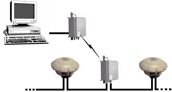
Figure 2-1 illustrates a Savi RF Relay connected to a host
computer that communicates by RF with a wired network
of remote SaviReaders.
)LJXUH 7ZR5)5HOD\V/LQNLQJD &RPSXWHUZLWKD:LUHG1HWZRUN
RF Relay
1001
SaviReader #31 SaviReader #32
RF Relay
1003
1HWZRUN3ODFHPHQW
6DYL5)5HOD\5)5DQG5)5,QVWDOODWLRQ*XLGH
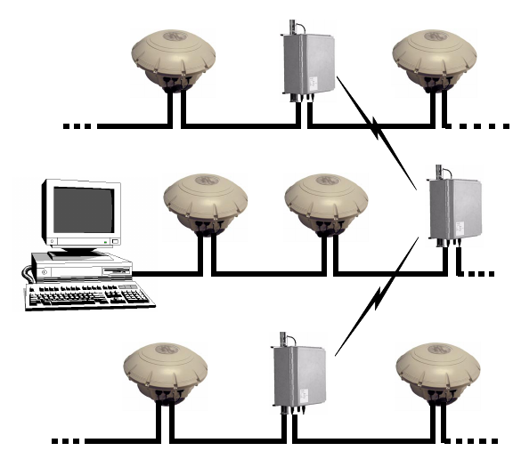
Figure 2-2 illustrates Savi RF Relays that make connections
among a wired network of SaviReaders attached to a host
computer and two other wired networks of SaviReaders.
)LJXUH 6DYL5)5HOD\V/LQNLQJ7ZR6DYL5HDGHU:LUHG1HWZRUNV
SaviReader #32SaviReader #31
SaviReader #12SaviReader #11
SaviReader #42
5)5HOD\
5)5HOD\
SaviReader #41 5)5HOD\
1HWZRUN3ODFHPHQW
6DYL5)5HOD\5)5DQG5)5,QVWDOODWLRQ*XLGH
0RXQWLQJWKH5HOD\&RPSRQHQWV
As you decide where to mount RF Relay components in relation
to each other, keep in mind that the up/down converter connects
to the NEMA enclosure through a coaxial cable with a maximum
length of 153 dm (50 feet). The up/down converter (model
UDC2.4B-0C only) connects to the antenna filter through a
46 cm (18 in.) coaxial cable. The up/down converter model
UDC2.4C-0C connects directly to the antenna using the 61 cm
(24 in.) coaxial cable.
Although you can move a Savi RF Relay after you install it,
Savi recommends that you make sure each relay is operational
before you install it in a position that is hard to reach.
Mounting kits available from Savi Technology include hardware
to mount a Savi RF Relay on a pole (wooden, metal, or concrete),
wall, or a tripod. Please refer to the instructions included with the
mounting kit for proper installation.
1HWZRUN3ODFHPHQW
6DYL5)5HOD\5)5DQG5)5,QVWDOODWLRQ*XLGH
0RXQWLQJWKH$QWHQQD
Be sure to mount the antenna so that its radiating element is clear
of obstructions.
Note: Note that the antenna is not grounded; therefore Savi
recommends that you install a lightning-protection
device in your system. Since the antenna has vertical
gain, it is very important to mount it so that the
radiating element is vertical.
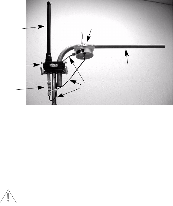
)LJXUH 0RXQWHG$QWHQQDZLWK0RGHO8'&&&&RQYHUWHU
Up/down Converter
Universal
Savi Mount Tube
Antenna
Radiating
Element
Mounting
Block
Coaxial Cables
(Model UDC2.4C-0C)
3K\VLFDO&RQQHFWLRQV
6DYL5)5HOD\5)5DQG5)5,QVWDOODWLRQ*XLGH
3K\VLFDO&RQQHFWLRQV
The rest of this chapter provides instructions about how to install
an RF Relay and verify that your installation is correct.
» To install an RF Relay:
1. Attach the filter to the antenna if you are using an up/down
converter model UDC2.4B-0C.
2. Mount the RF Relay, antenna or antenna/filter combination,
and up/down converter.
Refer to the instructions provided in the Savi Mounting Kit.
3. Connect the RF Relay, antenna or antenna/filter combination,
and up/down converter to each other using the provided
coaxial cables.
4. Connect the power cable to the RF Relay.
5. Connect the network cable(s) to a computer or to a
SaviReader in a daisy-chain configuration.
Note: After you have installed at least two RF Relays,
you can verify that they are installed correctly
as described in “Verification” on page 2-11.
$WWDFKLQJWKH)LOWHUWRWKH$QWHQQD
Note: The filter is used only with the up/down converter
model UDC2.4B-0C.
The filter is designed to fit onto the connector end of the antenna.
Attach the filter by screwing it onto the antenna. The coaxial
cable that will run between the up/down converter and the
antenna will then attach directly to the filter.
3K\VLFDO&RQQHFWLRQV
6DYL5)5HOD\5)5DQG5)5,QVWDOODWLRQ*XLGH
»To connect the antenna/filter to the up/down converter:
1. Attach the male connector of the 46 cm (18 in.) cable to
the port on the end of the filter.
2. Turn the connector clockwise until it is firmly attached
to the filter.
3. Attach the cable’s female connector to the port that is near
the center of the up/down converter.
)LJXUH 0RXQWLQJWKH$QWHQQDZLWK)LOWHU
4. Turn the connector clockwise until it is firmly attached to the
up/down converter.
,QWHUFRQQHFWLQJWKH5HOD\&RPSRQHQWV
To connect the components of the RF Relay to each other, you
must connect the RF Relay itself to the up/down converter. The
system does not function if you connect the RF Relay directly
to the filter (or to the antenna).
Do not connect or disconnect the up/down
converter while the RF Relay is connected to
a power supply.
Up/down Converter
Universal
Savi Mount Tube
Antenna
Radiating
Element
Mounting
Block
Coaxial Cables
(Model UDC2.4B-0C)
Filter
3K\VLFDO&RQQHFWLRQV
6DYL5)5HOD\5)5DQG5)5,QVWDOODWLRQ*XLGH
»To connect the up/down converter to the NEMA enclosure:
1. Using the 153 dm (50 ft.) cable, which has a male connector
at each end, attach the smaller of the connectors to the
antenna-cable port on the RF Relay.
The antenna-cable port is the farthest to the left side on the
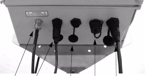
bottom of the relay NEMA enclosure, as shown in Figure 2-5.
)LJXUH 5)5HOD\%RWWRP9LHZ
2. Turn the connector clockwise until it is firmly attached to
the antenna-cable port.
3. For the Model UDC2.4B-0C converter: Attach the other
connector to the female port on the side of the up/down
converter.
4. For the Model UDC2.4C-0C converter: Attach the other
connector to the converter port marked IU (indoor unit).
5. Turn the connector clockwise until it is firmly attached to
the up/down converter.
Antenna
Cable
Network In Network Out AC Fuse
Holder
Power
Cable

3K\VLFDO&RQQHFWLRQV
6DYL5)5HOD\5)5DQG5)5,QVWDOODWLRQ*XLGH
&RQQHFWLQJWKH3RZHU&DEOH
The power source can be 12 to 24 VDC, 110 VAC, or 220 VAC.
The RF Relay does not require modifications for different power
sources. An appropriate power cable is supplied, depending on
the requirements specified when the order was placed:
•The 220 VAC cable terminates in a European connector.
•The 110 VAC cable terminates in a North American
connector.
You can also power the RF Relay from a Savi Solar Power
Module, or by vehicle power. A fixed-length, molded cable
is supplied with the Solar Power Module. The Vehicle Power
Cable can be purchased as an accessory item.
Make sure that the antenna (with filter for the
model UDC2.4B-0C up/down converter) is
connected before you connect the power cable.
»To connect the power cable:
1. On the bottom of the Relay NEMA enclosure, plug the
power cable’s female connector into the POWER socket
located next to the AC fuse holder. See Figure 2-5 on
page 2-8.
2. Push the locking ring forward and rotate it clockwise
until you feel resistance.
3. Then rotate the connector slightly further in the same
direction until you distinctly feel it “click” into place
as it locks.
4. Connect the other end of the power cable to an appropriate
power source, such as the Savi Solar Power Module or an
AC outlet.
3K\VLFDO&RQQHFWLRQV
6DYL5)5HOD\5)5DQG5)5,QVWDOODWLRQ*XLGH
&RQQHFWLQJWKH1HWZRUN&DEOHV
Two network cables connect a Savi RF Relay to a SaviReader
or to a host computer through a network data cable.
&RQQHFWLQJWKH1HWZRUN&DEOHV
WR WKH5) 5HOD\
Note: You will use the same Savi-supplied network cables
whether you are installing a SaviNet or a LonWorks
network configuration (unless you are connecting to
a host computer).
»To connect the network cables:
1. While aligning the notch, plug the cable’s female connector
into the NETWORK IN port on the RF Relay.
(See Figure 2-5 on page 2-8.)
2. Push the locking ring forward and rotate it clockwise until
you feel resistance. Then rotate the connector slightly further
until you distinctly feel it “click” into place as it locks.
3. Connect the other end of the cable either to a SaviReader
in a serial configuration or to a host computer.
If you are connecting to a computer, make sure you are using
the proper adapter cable.
If the RF Relay is installed between two readers in a wired network,
use the NETWORK OUT port to connect to the second reader.
9HULILFDWLRQ
6DYL5)5HOD\5)5DQG5)5,QVWDOODWLRQ*XLGH
9HULILFDWLRQ
To determine whether RF Relays have been installed correctly,
follow the steps below to perform a simple test.
»To verify installation:
1. Following the procedure described in the previous section,
connect one RF Relay to a SaviReader.
2. Connect a second RF Relay to a host computer.
3. From the host computer, use Savi Asset Manager (SAM)
software to perform a check-status event.
If the relays are installed properly, the reader will return its
status to the host computer.

6DYL5)5HOD\5)5DQG5)5,QVWDOODWLRQ*XLGH
0DLQWHQDQFH 3
With minimal care, a Savi RF Relay should perform flawlessly.
However, in the event that a problem with an RF Relay occurs,
the procedures in this chapter should help you troubleshoot it.
Changes or modifications to the equipment that are
not expressly approved by Savi Technology could
void the warranty and the authority to operate the
equipment.
Using the equipment in a manner not specified by
the manufacturer might impair the protection that
the equipment provides.
5HSDLUDQG0DLQWHQDQFH
6DYL5)5HOD\5)5DQG5)5,QVWDOODWLRQ*XLGH
5HSDLUDQG0DLQWHQDQFH
The Savi RF Relay is designed to need very little maintenance.
Savi RF Relays are manufactured with quality components and
are thoroughly tested before delivery.
As in any outdoor networked system, exposed RF Relay
components need to be checked occasionally for physical
damage. Periodically check cables and enclosures that are
exposed to the elements to make sure they have not been
damaged.
5HSODFLQJWKH)XVH
If the RF Relay power fails, follow the troubleshooting tips found
in Table 3-10. You may need to change the AC fuse.
»To replace the fuse:
1. Unscrew the fuse holder cover, which is attached to the
RF Relay by a short chain.
The fuse holder is located on the bottom of the RF Relay
and to the left of the POWER socket, as shown in Figure 2-5
on page 2-8.
2. Push in the fuse holder cap and unscrew it counter-clockwise.
3. Remove the fuse from the fuse holder cap and replace it.
The RF Relay uses a 4-amp, 250-volt fuse.
4. While aligning the notches in the fuse holder cap, push it into
the receptacle and screw it clockwise.
5. Screw the fuse holder cover back into place on the RF Relay.
5HSDLUDQG0DLQWHQDQFH
6DYL5)5HOD\5)5DQG5)5,QVWDOODWLRQ*XLGH
&KDQJLQJ&KDQQHOV
Savi RF Relays have been factory configured for operation; no
settings or adjustments are required. However, it may become
necessary to change the transmit and receive channels because
of other equipment within the same area operating at the same
frequency. The RF Modem inside the RF Relay can be set to
transmit and receive at any one of 240 frequencies (channels).
Frequency codes 10–250 are assigned to these channels.
Table 3-9 on page 3-15 lists the frequency codes and their
corresponding frequency. The steps following describe how to
configure the RF Relay for operation at a different frequency.
Note: RF Relays are preset at the factory to channel 100.
0RGHO5)52QO\
5HTXLUHG(TXLSPHQW
The following equipment is required to reconfigure channels:
•RS-485 Adapter Cable (Savi P/N 830-00911-001 or
830-00911-002)
•DB25M to DB9F Adapter (to connect to the PC serial port)
•PC with a HyperTerminal program
Note: It is not necessary to open the relay cover to change
transmit and receive frequencies for the RFR-100.

5HSDLUDQG0DLQWHQDQFH
6DYL5)5HOD\5)5DQG5)5,QVWDOODWLRQ*XLGH
»To change channels for the RFR-100:
1. Connect the RS-485 adapter cable to the RS-485 port on
the RFR-100 and to the RS-232 port on the PC using the
DB25M to DB9F adapter.
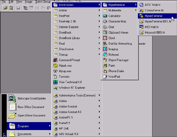
2. From the Windows Start menu, select
Programs>Accessories>Hyperterminal>HyperTerminal.
The system displays the Connection Description window.
Note: If your screen displays a Hyperterminal program
folder, double-click the Hypertrm.exe icon.
)LJXUH $FFHVVWRWKH+\SHU7HUPLQDO3URJUDP
3. In the Connection Description window, enter a Name of your
choice for the connection (for example 38K) and select an
icon.
4. Click OK.
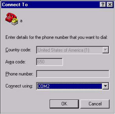
The system displays the Connect To window.

5HSDLUDQG0DLQWHQDQFH
6DYL5)5HOD\5)5DQG5)5,QVWDOODWLRQ*XLGH
)LJXUH +\SHU7HUPLQDO&RQQHFW7R:LQGRZ
5. Click the down arrow at the right of the Connect using field
to display the list of connections and select the COM port
that corresponds to the port to which the RF Relay is
connected.
6. Click OK.
The system displays the COM Properties window.
5HSDLUDQG0DLQWHQDQFH
6DYL5)5HOD\5)5DQG5)5,QVWDOODWLRQ*XLGH
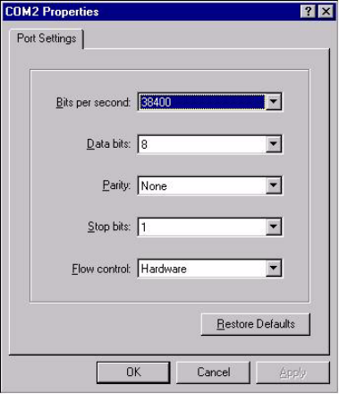
)LJXUH +\SHU7HUPLQDO&203URSHUWLHV:LQGRZ
7. Enter the port configuration settings as follows:
a. Bits per second - 38400
b. Data bits - 8
c. Parity - None
d. Stop bits - 1
e. Flow control - Hardware
Note: You can type the settings or click on the down arrow
to the right of each field to display a list from which
you select the appropriate setting.
8. Click OK.
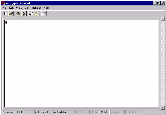
The system displays the HyperTerminal main window.
5HSDLUDQG0DLQWHQDQFH
6DYL5)5HOD\5)5DQG5)5,QVWDOODWLRQ*XLGH
)LJXUH +\SHU7HUPLQDO0DLQ:LQGRZ
9. Apply AC power to the RFR-100.
10. Wait 5 seconds for the unit to complete its start up checks.
11. Type at to open the file.
12. Hold down the Shift key on the PC keyboard and type +++
rapidly to place the modem into configuration mode.
Note: This may require multiple attempts.
13. Verify that OK displays in the PC HyperTerminal main
window.
Note: For each key you press from this point on the PC
screen will display double characters.

5HSDLUDQG0DLQWHQDQFH
6DYL5)5HOD\5)5DQG5)5,QVWDOODWLRQ*XLGH
14. From the range of 10 to 250 (the factory setting is CH 100),
determine the channel to use.
The new channel should be at least twenty
channels from the factory setting in order to
prevent interference.
15. Type ATS61=[insert new channel number] and press
Enter to set the new transmit channel.
16. Type ATS62=[insert new channel number] and press
Enter to set the new receive channel.
17. Type AT&V1 and press Enter to display the S Register
settings on the screen.
18. Verify that S Registers 61 and 62 are set to the channel that
you selected in Step 14. If not, repeat Steps 15 through 17.
19. Type AT&W to store the new configuration.
20. Remove the RS-485 adapter cable.
21. Disconnect and reconnect the power to the RFR-100 to return
it to data mode.

5HSDLUDQG0DLQWHQDQFH
6DYL5)5HOD\5)5DQG5)5,QVWDOODWLRQ*XLGH
0RGHO5)52QO\
5HTXLUHG(TXLSPHQW
The following equipment is required to reconfigure channels:
•RS-232 Cable, DB25F
•DB25M to DB9F Adapter (to connect to the PC serial port)
•PC with a HyperTerminal program and Windows 98 or NT
In order to change transmit and receive
frequencies, it is necessary to open the cover of the
RFR-200. To prevent voiding the warranty, do not
attempt any other modifications or maintenance.
»To change channels for the RFR-200:
1. Open the cover of the RF Relay.
2. Remove the DB25M RS-232 cable connector from the
RF modem.
3. Connect the RS-232 cable to the RS-232 port on the
RF modem and to the RS-232 port on the PC using the
DB25M to DB9F adapter.
4. From the Windows Start menu, select
Programs>Accessories>Hyperterminal>HyperTerminal.
The system displays the Connection Description window.
Note: If your screen displays a Hyperterminal program
folder, double-click the Hypertrm.exe icon.
5HSDLUDQG0DLQWHQDQFH
6DYL5)5HOD\5)5DQG5)5,QVWDOODWLRQ*XLGH
)LJXUH $FFHVVWRWKH+\SHU7HUPLQDO3URJUDP
5. In the Connection Description window, enter a Name of
your choice for the connection (for example 57K) and
select an icon.
6. Click OK.
The system displays the Connect To window.
5HSDLUDQG0DLQWHQDQFH
6DYL5)5HOD\5)5DQG5)5,QVWDOODWLRQ*XLGH
)LJXUH +\SHU7HUPLQDO&RQQHFW7R:LQGRZ
7. Click the down arrow at the right of the Connect using field
to display the list of connections and select the COM port
that corresponds to the port to which the RF Relay is
connected.
8. Click OK.
The system displays the COM Properties window.

5HSDLUDQG0DLQWHQDQFH
6DYL5)5HOD\5)5DQG5)5,QVWDOODWLRQ*XLGH
)LJXUH +\SHU7HUPLQDO&203URSHUWLHV:LQGRZ
9. Enter the port configuration settings as follows:
a. Bits per second - 57600
b. Data bits - 8
c. Parity - None
d. Stop bits - 1
e. Flow control - Hardware
Note: You can type the settings or click on the down arrow
to the right of each field to display a list from which
you select the appropriate setting.
10. Click OK.
The system displays the HyperTerminal main window.

5HSDLUDQG0DLQWHQDQFH
6DYL5)5HOD\5)5DQG5)5,QVWDOODWLRQ*XLGH
)LJXUH +\SHU7HUPLQDO0DLQ:LQGRZ
11. Apply AC power to the RFR-100.
12. Wait 5 seconds for the unit to complete its start up checks.
13. Click on Properties and verify proper COM port setting.
14. Click on Configure and verify port settings per Figure 3-7.
15. Click OK.
16. Click OK.
17. Hold down the Shift key on the PC keyboard and type +++
rapidly to place the modem into configuration mode.
Note: This may require multiple attempts.
18. Verify that OK displays in the PC HyperTerminal main
window.
Note: For each key you press from this point on the PC
screen will display double characters.

5HSDLUDQG0DLQWHQDQFH
6DYL5)5HOD\5)5DQG5)5,QVWDOODWLRQ*XLGH
19. From the range of 10 to 250 (factory setting is CH 100),
determine the channel to use.
The new channel should be at least twenty
channels from the factory setting in order
to prevent interference.
20. Type ATS61=[insert new channel number] and press
Enter to set the new transmit channel.
21. Type ATS62=[insert new channel number] and press
Enter to set the new receive channel.
22. Type AT&V1 and press Enter to display the S Register
settings on the screen.
23. Verify that S Registers 61 and 62 are set to the channel that
you selected in Step 19. If not, repeat Steps 20 through 22.
24. Type AT&W to store the new configuration.
25. Remove the RS-232 cable from the RF Modem and replace
the RS-232 cable from the LonWorks module.
26. Disconnect and reconnect the power to the RFR-200 to return
it to data mode.
27. Close the cover to the RF Relay and secure it shut.

5HSDLUDQG0DLQWHQDQFH
6DYL5)5HOD\5)5DQG5)5,QVWDOODWLRQ*XLGH
7DEOH )UHTXHQF\&RGH$VVLJQPHQWV0RGHO,60&
Freq.
Code
Up/Down
Converter
“C” Freq.
(GHz) Freq.
Code
Up/Down
Converter
“C” Freq.
(GHz) Freq.
Code
Up/Down
Converter
“C” Freq.
(GHz)
10 2.4500 40 2.4530 70 2.4560
11 2.4501 41 2.4531 71 2.4561
12 2.4502 42 2.4532 72 2.4562
13 2.4503 43 2.4533 73 2.4563
14 2.4504 44 2.4534 74 2.4564
15 2.4505 45 2.4535 75 2.4565
16 2.4506 46 2.4536 76 2.4566
17 2.4507 47 2.4537 77 2.4567
18 2.4508 48 2.4538 78 2.4568
19 2.4509 49 2.4539 79 2.4569
20 2.4510 50 2.4540 80 2.4570
21 2.4511 51 2.4541 81 2.4571
22 2.4512 52 2.4542 82 2.4572
23 2.4513 53 2.4543 83 2.4573
24 2.4514 54 2.4544 84 2.4574
25 2.4515 55 2.4545 85 2.4575
26 2.4516 56 2.4546 86 2.4576
27 2.4517 57 2.4547 87 2.4577
28 2.4518 58 2.4548 88 2.4578
29 2.4519 59 2.4549 89 2.4579
30 2.4520 60 2.4550 90 2.4580
31 2.4521 61 2.4551 91 2.4581
32 2.4522 62 2.4552 92 2.4582
33 2.4523 63 2.4553 93 2.4583
34 2.4524 64 2.4554 94 2.4584
35 2.4525 65 2.4555 95 2.4585
36 2.4526 66 2.4556 96 2.4586
37 2.4527 67 2.4557 97 2.4587
38 2.4528 68 2.4558 98 2.4588
5HSDLUDQG0DLQWHQDQFH
6DYL5)5HOD\5)5DQG5)5,QVWDOODWLRQ*XLGH
39 2.4529 69 2.4559 99 2.4589
100 2.4590 130 2.4620 160 2.4650
101 2.4591 131 2.4621 161 2.4651
102 2.4592 132 2.4622 162 2.4652
103 2.4593 133 2.4623 163 2.4653
104 2.4594 134 2.4624 164 2.4654
105 2.4595 135 2.4625 165 2.4655
106 2.4596 136 2.4626 166 2.4656
107 2.4597 137 2.4627 167 2.4657
108 2.4598 138 2.4628 168 2.4658
109 2.4599 139 2.4629 169 2.4659
110 2.4600 140 2.4630 170 2.4660
111 2.4601 141 2.4631 171 2.4661
112 2.4602 142 2.4632 172 2.4662
113 2.4603 143 2.4633 173 2.4663
114 2.4604 144 2.4634 174 2.4664
115 2.4605 145 2.4635 175 2.4665
116 2.4606 146 2.4636 176 2.4666
117 2.4607 147 2.4637 177 2.4667
118 2.4608 148 2.4638 178 2.4668
119 2.4609 149 2.4639 179 2.4669
120 2.4610 150 2.4640 180 2.4670
121 2.4611 151 2.4641 181 2.4671
122 2.4612 152 2.4642 182 2.4672
123 2.4613 153 2.4643 183 2.4673
124 2.4614 154 2.4644 184 2.4674
125 2.4615 155 2.4645 185 2.4675
126 2.4616 156 2.4646 186 2.4676
127 2.4617 157 2.4647 187 2.4677
7DEOH )UHTXHQF\&RGH$VVLJQPHQWV0RGHO,60&
Freq.
Code
Up/Down
Converter
“C” Freq.
(GHz) Freq.
Code
Up/Down
Converter
“C” Freq.
(GHz) Freq.
Code
Up/Down
Converter
“C” Freq.
(GHz)
5HSDLUDQG0DLQWHQDQFH
6DYL5)5HOD\5)5DQG5)5,QVWDOODWLRQ*XLGH
128 2.4618 158 2.4648 188 2.4678
129 2.4619 159 2.4649 189 2.4679
190 2.4680 211 2.4701 232 2.4722
191 2.4681 212 2.4702 233 2.4723
192 2.4682 213 2.4703 234 2.4724
193 2.4683 214 2.4704 235 2.4725
194 2.4684 215 2.4705 236 2.4726
195 2.4685 216 2.4706 237 2.4727
196 2.4686 217 2.4707 238 2.4728
197 2.4687 218 2.4708 239 2.4729
198 2.4688 219 2.4709 240 2.4730
199 2.4689 220 2.4710 241 2.4731
200 2.4690 221 2.4711 242 2.4732
201 2.4691 222 2.4712 243 2.4733
202 2.4692 223 2.4713 244 2.4734
203 2.4693 224 2.4714 245 2.4735
204 2.4694 225 2.4715 246 2.4736
205 2.4695 226 2.4716 247 2.4737
206 2.4696 227 2.4717 248 2.4738
207 2.4697 228 2.4718 249 2.4739
208 2.4698 229 2.4719 250 2.4740
209 2.4699 230 2.4720
210 2.4700 231 2.4721
7DEOH )UHTXHQF\&RGH$VVLJQPHQWV0RGHO,60&
Freq.
Code
Up/Down
Converter
“C” Freq.
(GHz) Freq.
Code
Up/Down
Converter
“C” Freq.
(GHz) Freq.
Code
Up/Down
Converter
“C” Freq.
(GHz)

7URXEOHVKRRWLQJ
6DYL5)5HOD\5)5DQG5)5,QVWDOODWLRQ*XLGH
7URXEOHVKRRWLQJ
Table 3-10 following lists problems that could occur with the
Savi RF Relay, along with possible solutions.
In the unlikely event that a Savi RF Relay fails or problems
occur that simple troubleshooting cannot solve, Savi Technical
Support may recommend that you return the Savi RF Relay to
Savi Technology.
7DEOH 3RVVLEOH3UREOHPVDQG6ROXWLRQV
Problem Solution
No power –Confirm that power is available to the RF Relay
by checking all circuit breakers, power switches,
and safety switches.
–If AC- powered, verify the presence and voltage
of the power by connecting a test unit to the power
source. Check the AC fuse. (See “Replacing the
Fuse” on page 3-2.)
–If solar-powered, verify the output voltage of the
module to be 12 VDC.
–Verify that the power cable is securely plugged
into the power source and the RF Relay input.
–Try a different power source.
–Replace the power cable.
No data communication –Verify that the network cable is securely plugged
into the RF Relay.
–Verify that the network cable is securely plugged
into the correct COM port on the computer.
COM1 is usually a DB9 connector. COM2 may
be a DB9 or DB25 connector.
–Verify that the cable itself is not damaged.
COM port unavailable
(possibly used for
another device such
as a mouse)
–Connect the RF Relay cable to another COM port.
–Verify that the software setting matches the COM
port where the RF Relay is connected.
Unknown –Turn the RF Relay power off and then back on.
–Call Savi Technical Support.
*HWWLQJ$VVLVWDQFH
6DYL5)5HOD\5)5DQG5)5,QVWDOODWLRQ*XLGH
*HWWLQJ$VVLVWDQFH
If you have trouble with the product, after you have checked your
connections and the Savi RF Relay (RFR-100 and RFR-200)
Installation Guide, contact Savi Technical Support.
7HFKQLFDO6XSSRUW
To contact Savi Technical Support:
•Telephone 1-888-994-SAVI (7284) between 5:00 a.m.
and5:00p.m.
, Pacific Time
•Or send e-mail to help@savi.com at any time
Whether you contact Savi by telephone or e-mail, please have
the exact sequence of operations (if possible) that caused the
problem and the following information available:
•Site location
•Incident description
•Estimated severity level of the incident
•Model number and version
•Serial number
•Computer type (Gateway, Dell, etc.) and model
•Operating system and service pack level
•Network protocol
Please contact Savi Technical Support if you have suggestions
for how Savi can improve the next revision of the product or this
manual.