Savi Technology SATS-V1 RF tag reader/transmitter User Manual ULDReader
Savi Technology Inc RF tag reader/transmitter ULDReader
UserManual.wiki
>
Savi Technology
>
SATS V1 User Manual
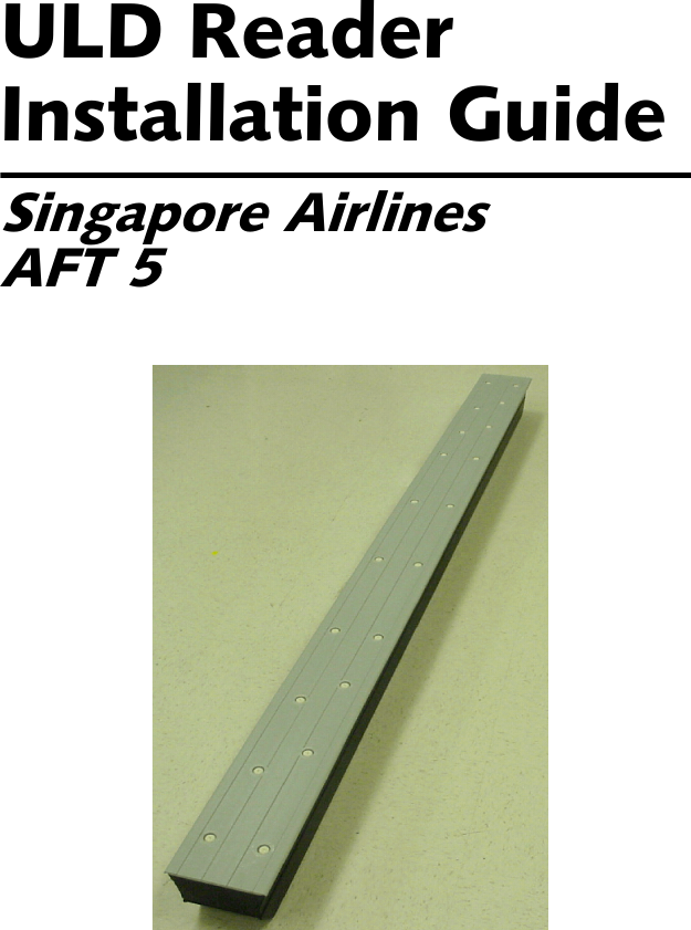
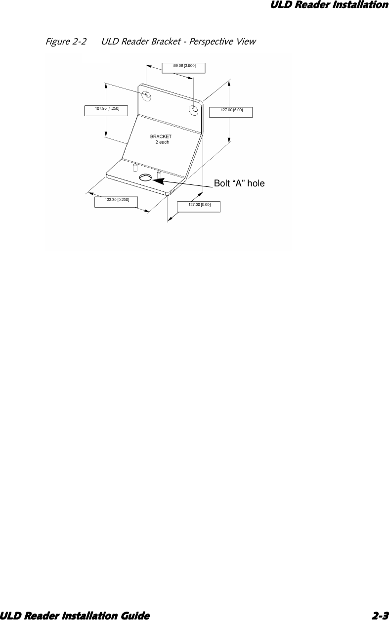
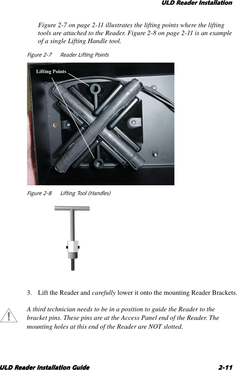
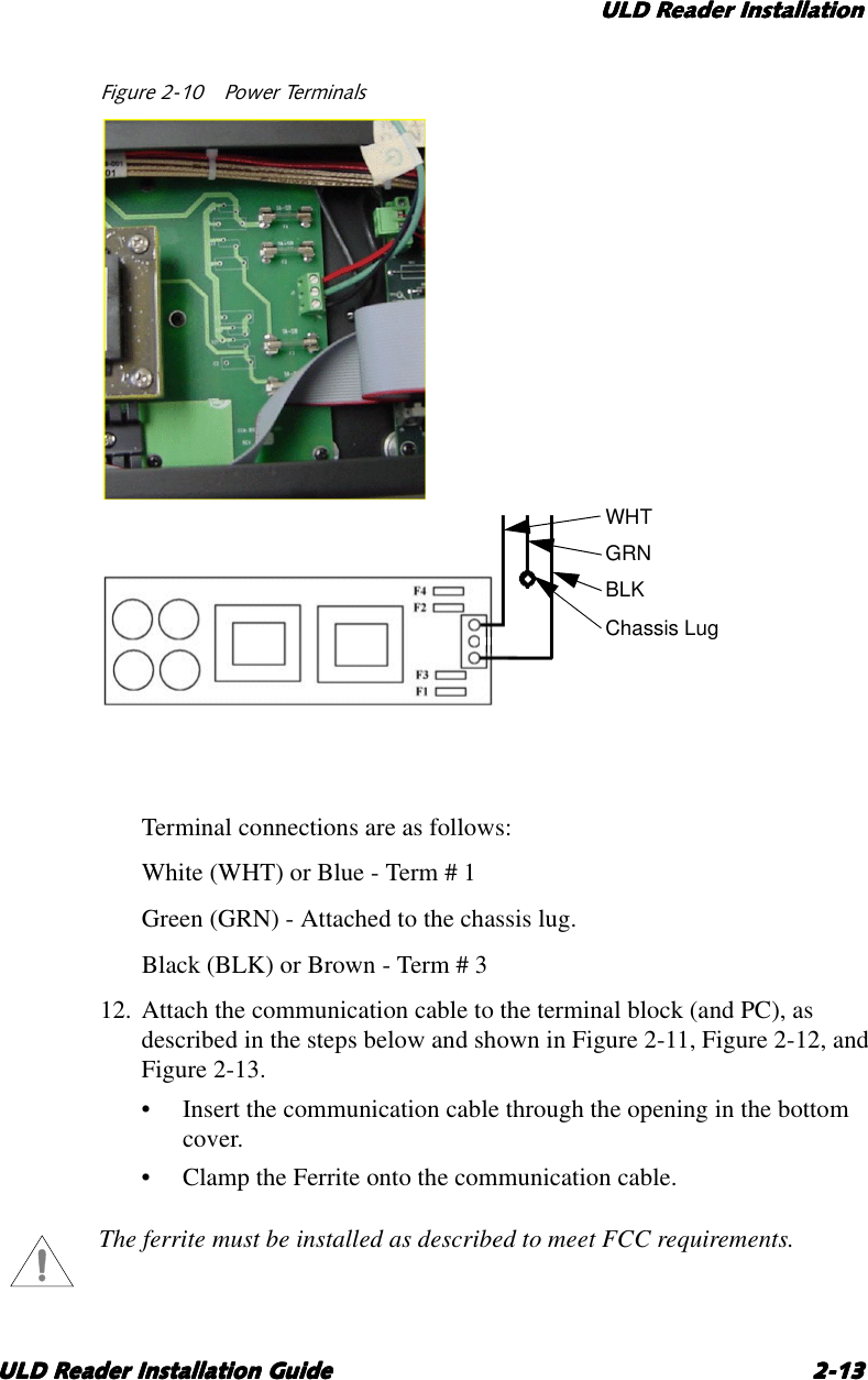
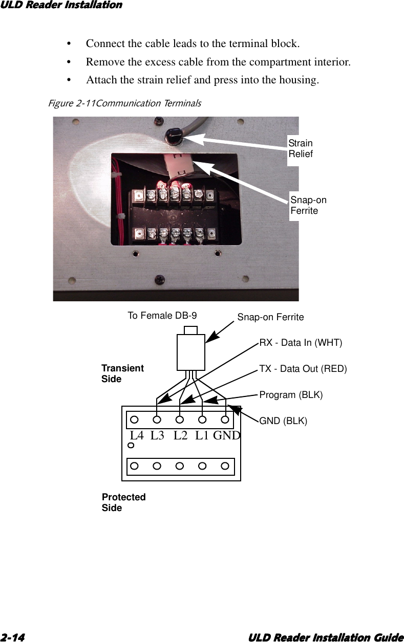
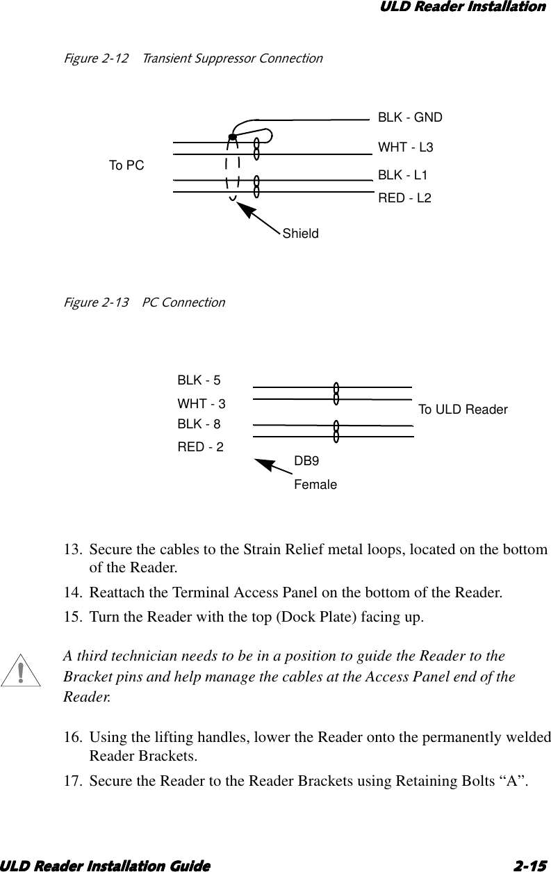
ULD Reade
Navigation menu
Upload a User Manual
Namespaces
Wiki Guide
HTML
PDF
Info
Views
User Manual
Discussion / Help
Navigation