Savi Technology SATS-V1 RF tag reader/transmitter User Manual ULDReader
Savi Technology Inc RF tag reader/transmitter ULDReader
ULD Reade
ULD Reader
Installation Guide
Singapore Airlines
AFT 5
ii
iiii
ii
First edition June 2000
Part number 260-02920-001 Rev. B
Copyright ©2000 Savi Technology Incorporated. All rights reserved. Printed in the United
States of America.
Information in this manual is subject to change without notice and does not represent a
commitment from the vendor. The software and/or databases described in this document are
furnished under alicense agreement or nondisclosure agreement. The software and/or
databases may be used or copied only in accordance with the terms of the agreement. It is
against the law to copy the software on any medium except as specifically allowed in the
license or nondisclosure agreement.
Savi, Batch Collection, and TyTag are registered trademarks and Adaptive Routing, Enhanced
Batch Collection, Hand Held Interrogator (HHI), Savi Asset Manager, Savi Fixed Interrogator,
Savi GateReader, Savi Mobile Manager, Savi MobileReader, SaviReader, Savi Retriever,
Savi SDK, Savi System, SaviTag, Savi Tools, and SealTag are trademarks of Savi Technology
Incorporated.
Other product names mentioned in this guide may be trademarks or registered trademarks of
their respective owners and are hereby acknowledged.
This manual was produced by the Savi Technology Publications Group. Please address any
comments or requests for updates to:
Savi Technology
Publications Manager
615 Tasman Drive
Sunnyvale, CA 94089-1707
www.savi.com
Phone: 1-888-994-SAVI
1-408-743-8000
Fax: 1-408-543-8650
Author: John Gamble
Contributors:Richard Wilson, Jan Hodges, and Van Clark
Layout Design and Production: John Gamble

Regulatory Approvals
Regulatory ApprovalsRegulatory Approvals
Regulatory Approvals
iii
iiiiii
iii
Regulatory Approvals
Federal Communications Commission (FCC)
Notice
The Federal Communications Commission has established technical standards regarding radio
frequency energy emitted by computer devices. This equipment has been tested and found to
comply with the limits for aClass Adigital device, pursuant to Part 15 of the FCC Rules. These
limits are designed to provide reasonable protection against harmful interference when the
equipment is operated in acommercial environment. This equipment generates, uses, and can
radiate radio frequency energy and, if not installed and used in accordance with the instruction
manual, may cause harmful interference with radio/TV reception. Operation of this equipment
in aresidential area is likely to cause harmful interference in which case the user will be
required to correct the interference at his own expense.
Changes or modifications to this equipment that are not expressly
approved by Savi Technology could void the warranty and the
authority to operate this equipment.
Savi Technology is not responsible for radio/TV interference caused
by using unauthorized cable or by making unauthorized changes to
this equipment.
Product Safety
Using this equipment in amanner not specified by the manufacturer can impair the protection
that the equipment provides.

Conventions in this Guide
The following table explains guide conventions and typography
usage.
Guide Conventions
Example Meaning and Use
Caution notices call attention to the possibility
of damaging the product, the system, or your
work (for example, potential loss of data).
Warning notices call attention to the possibility
of injury to people.
Examples provide ascenario to further explain
the preceding direction or procedure.
Note: Notes call attention to facts or advice that deserve
special attention.
Terminal Locked Bold type is used for prompts, window and field
names, and other text as displayed on the screen.
A:\INSTALL Bold type is also used for text you enter exactly as
shown.
1005 DATA Monospaced type is used for system messages,
examples of data files, program code, and other text
where column alignment is important.
name.bmp or tag_id Italic type is used for emphasis of aword or phrase
that is new or especially important.
Continue with ... Italic type is also used for notes.
Ctrl +ZUsed for akeyboard control codes or manual key-
strokes. This example tells you to hold the Ctrl key
while you press the Zkey.
Example
Getting Assistance
Getting AssistanceGetting Assistance
Getting Assistance
v
vv
v
Getting Assistance
If you have trouble with the product, after you have checked your
connections and the ULD Reader Installation Guide,contact Savi
Technical Support.
Technical Support
To contact Savi Technical Support:
• Telephone 1-888-994-SAVI (North America only) or 1-408-743-8000
between 8:00 a.m. and 5:00 p.m. Pacific Time.
•Sendan e-mail to help@savi.com.
Whether you contact Savi by telephone or e-mail, please have
the following product information ready, along with the exact sequence
of operations (if possible) that caused the error:
•Equipmenttype and location
• Model number and version
•Serialnumber
Getting Assistance
Getting AssistanceGetting Assistance
Getting Assistance
vi
vivi
vi
Contents
ULD Reader Installation Guide
ULD Reader Installation GuideULD Reader Installation Guide
ULD Reader Installation Guide vii
viivii
vii
Regulatory Approvals . . . . . . . . . . . . . . . . . . . . . . . . . . . . . . . . . . . . . iii
Conventions in this Guide . . . . . . . . . . . . . . . . . . . . . . . . . . . . . . . . . . iv
Getting Assistance . . . . . . . . . . . . . . . . . . . . . . . . . . . . . . . . . . . . . . . .v
Technical Support . . . . . . . . . . . . . . . . . . . . . . . . . . . . . . . . . . . . . v
Chapter 1: Introduction
Summary ..............................................1-2
Chapter 2: ULD Reader Installation
Mechanical Description . . . . . . . . . . . . . . . . . . . . . . . . . . . . . . . . . . 2-2
ULD Reader . . . . . . . . . . . . . . . . . . . . . . . . . . . . . . . . . . . . . . . . 2-2
ULD Reader Bracket . . . . . . . . . . . . . . . . . . . . . . . . . . . . . . . . . 2-2
Bracket Removal and Installation . . . . . . . . . . . . . . . . . . . . . . . . . . . 2-4
Removing Deck Plates . . . . . . . . . . . . . . . . . . . . . . . . . . . . . . . . 2-4
Reader Bracket Installation for TTTV, ETV, and BV . . . . . . . . 2-4
Reader Bracket Installation for Workstations . . . . . . . . . . . . . . 2-7
Reader Installation . . . . . . . . . . . . . . . . . . . . . . . . . . . . . . . . . . . . . 2-10
Temporary Reader Housing Installation . . . . . . . . . . . . . . . . . 2-10
Final Reader Installation . . . . . . . . . . . . . . . . . . . . . . . . . . . . . 2-10
Required Installation Tools . . . . . . . . . . . . . . . . . . . . . . . . . . . . . . . 2-16
Installation Materials . . . . . . . . . . . . . . . . . . . . . . . . . . . . . . . . . . . 2-17
Reader Locations . . . . . . . . . . . . . . . . . . . . . . . . . . . . . . . . . . . . . . 2-18
Installation Sheets . . . . . . . . . . . . . . . . . . . . . . . . . . . . . . . . . . . . . . 2-22
viii
viiiviii
viii ULD Reader Installation Guide
ULD Reader Installation GuideULD Reader Installation Guide
ULD Reader Installation Guide
ULD Reader Installation Guide
ULD Reader Installation GuideULD Reader Installation Guide
ULD Reader Installation Guide ix
ixix
ix
Figures 1
Figure Page
2-1 Savi ULD Reader -Side View . . . . . . . . . . . . . . . . . . . . . . . . . 2-2
2-2 ULD Reader Bracket -Perspective View. . . . . . . . . . . . . . . . . 2-3
2-3 Reader Bracket and Mounting Bolts . . . . . . . . . . . . . . . . . . . . 2-5
2-4 Bracket Mounting Fixture . . . . . . . . . . . . . . . . . . . . . . . . . . . . 2-6
2-5 Reader Bracket and Mounting Bolts . . . . . . . . . . . . . . . . . . . . 2-8
2-6 Bracket Mounting Fixture . . . . . . . . . . . . . . . . . . . . . . . . . . . . 2-8
2-7 Reader Lifting Points . . . . . . . . . . . . . . . . . . . . . . . . . . . . . . . 2-11
2-8 Lifting Tool (Handles) . . . . . . . . . . . . . . . . . . . . . . . . . . . . . . 2-11
2-9 Terminal Access Panels . . . . . . . . . . . . . . . . . . . . . . . . . . . . . 2-12
2-10 Power Terminals. . . . . . . . . . . . . . . . . . . . . . . . . . . . . . . . . . . 2-13
2-11 Communication Terminals. . . . . . . . . . . . . . . . . . . . . . . . . . . 2-14
2-12 Transient Suppressor Connection . . . . . . . . . . . . . . . . . . . . . 2-15
2-13 PC Connection . . . . . . . . . . . . . . . . . . . . . . . . . . . . . . . . . . . . 2-15
2-14 TTV 1 - 3 Location . . . . . . . . . . . . . . . . . . . . . . . . . . . . . . . . 2-18
2-15 BV 1and 2Location . . . . . . . . . . . . . . . . . . . . . . . . . . . . . . . 2-19
2-16 ETV 1 - 3 Location . . . . . . . . . . . . . . . . . . . . . . . . . . . . . . . . 2-20
2-17 Workstation 1 - 12 Location. . . . . . . . . . . . . . . . . . . . . . . . . . 2-21
2-18 TTTV1, Level 1Hardware Diagram . . . . . . . . . . . . . . . . . . . 2-23
2-19 TTTV 2, Level 1Hardware Diagram. . . . . . . . . . . . . . . . . . . 2-24
2-20 TTTV 3, Level 1Hardware Diagram. . . . . . . . . . . . . . . . . . . 2-25
2-21 BV 1, Level 2Hardware Diagram . . . . . . . . . . . . . . . . . . . . . 2-26
2-22 BV 2, Level 1Hardware Diagram . . . . . . . . . . . . . . . . . . . . . 2-27
2-23 ETV 1, Level 1Hardware Diagram. . . . . . . . . . . . . . . . . . . . 2-28
2-24 ETV 2, Level 1Hardware Diagram. . . . . . . . . . . . . . . . . . . . 2-29
2-25 ETV 3, Level 1Hardware Diagram. . . . . . . . . . . . . . . . . . . . 2-30
2-26 Workstation 1-12, MCP 1, Level 1Hardware Diagram. . . . . 2-31
x
xx
x ULD Reader Installation Guide
ULD Reader Installation GuideULD Reader Installation Guide
ULD Reader Installation Guide

ULD Reader Installation Guide
ULD Reader Installation GuideULD Reader Installation Guide
ULD Reader Installation Guide 1-1
1-11-1
1-1
1Introduction 1
This guide provides information for installing Unit Load Device (ULD)
Readers for Singapore Airport Terminal Services (SATS) in support of the
ULD Tracking System, for tracking cargo pallets and containers. SATS
provides cargo handling services for major international airlines in Singapore.
There are five Air Freight Terminals (ATF) in operation today, with Terminal
6currently under construction.
AFT5 handles all Singapore Airlines and SilkAir cargo, while AFT1 to AFT4
handle cargo from other airlines.
This document details the procedures for the installation within AFT5.
Introduction
IntroductionIntroduction
Introduction
1-2
1-21-2
1-2 ULD Reader Installation Guide
ULD Reader Installation GuideULD Reader Installation Guide
ULD Reader Installation Guide
Summary
In AFT5, pallets and containers (ULDs), are handled by aMaterial Handling
System (MHS). They are stored in amulti-level ULD storage system with a
capacity of 1316 ULDs within the MHS. Electronic sensors are strategically
located on conveyors and equipment to monitor movement of ULDs.
Signals are transmitted and analyzed by aDEC VAX mini computer through a
comprehensive network. ULDs can be introduced into, transferred within, or
removed from the storage system through 12 Workstations, 3Turn-Table
Transfer Vehicles (TTTV), 3Elevated Transfer Vehicles (ETV), and 2Bridge
Vehicle (BV) stations.
The ETVs convey ULDs between the airside roller decks and landside
workstations. The BVs travel along level Dand Fof the ULD storage system
and transfer ULDs from the import zone to the export zone. The TTTVs
provide alink between the ramp mobile equipment (dolly) and the airside
roller decks.
To manage the ULD tracking within AFT5, aSAVI RFID system is to be
installed which integrates with the existing ICS. This new Savi system
comprises 26 readers and 12,000 ULD tags. It provides 99.9% successful
reads to the Inventory Control System (ICS) when ULDs are moving at
speeds of up to 0.5 meters per second.
The Savi ULD Reader is to be installed between and below the conveyor
system rollers on the transfer vehicles.
The reader output interface is an RS-232 interface to ahost PC-computer.

ULD Reader Installation Guide
ULD Reader Installation GuideULD Reader Installation Guide
ULD Reader Installation Guide 2-1
2-12-1
2-1
2ULD Reader
Installation 2
This chapter provides information for installing ULD Readers, including the
following topics:
• Mechanical Description
• Existing Bracket Removal and Reader Bracket Installation
•ReaderInstallation
• Installation Tools
• Installation Materials
•ReaderLocations
This chapter also provides installation sheets which consist of:
• Hardware diagrams for the installation locations
• Sign-off fields to be filled out and signed when work is complete for a
specific location
ULD Reader Installation
ULD Reader InstallationULD Reader Installation
ULD Reader Installation
2-2
2-22-2
2-2 ULD Reader Installation Guide
ULD Reader Installation GuideULD Reader Installation Guide
ULD Reader Installation Guide
Mechanical Description
The Reader and the two Reader Brackets securing it to the conveyor comprise
the basic components set for each ULD Reader system. This section provides
diagrams and abrief description of these components:
•ULDReader on page 2-2
•ULDReader Bracket on page 2-2
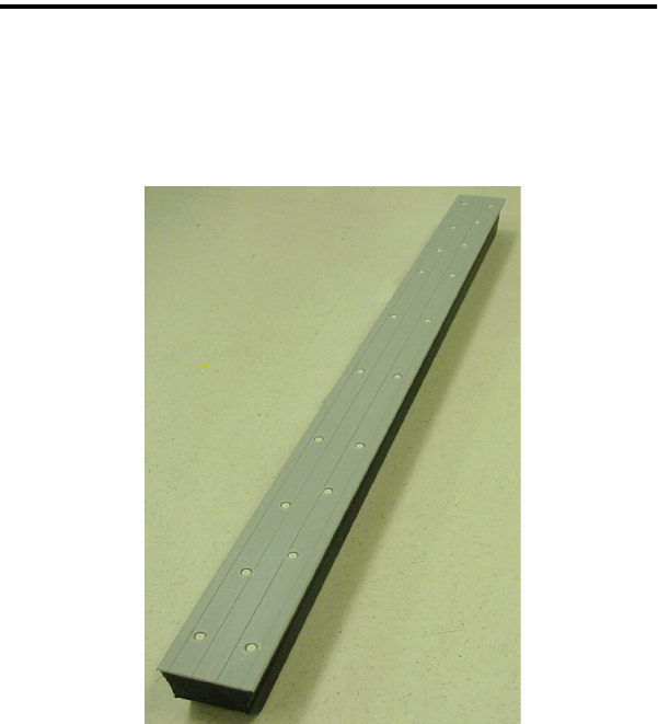
ULD Reader
Figure 2-1 provides aside view of aULD Reader. Readers are installed
between rollers and below the conveyor system. This figure also shows the
relationship between the Reader and the ULD Reader Brackets and Retaining
Bolts securing the components together.
Different locations require specific Reader configurations. Information on
where and how many Readers are installed for specific locations is covered in
“Reader Locations” on page 2-18.
Figure 2-1 Savi ULD Reader - Side View
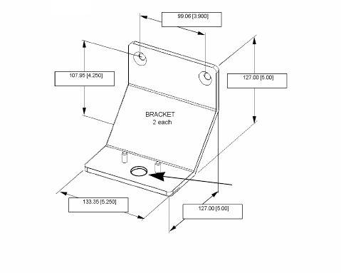
ULD Reader Bracket
The Reader rests on, and is attached to the roller suspension rail with ULD
Reader Brackets. Figure 2-1 shows aside view of aULD Reader Bracket
supporting aReader. Figure 2-2 on page 2-3 shows adimensioned perspective
of aReader Bracket.
Retaining Bolt “A”
Bracket
ULD Reader Installation
ULD Reader InstallationULD Reader Installation
ULD Reader Installation
ULD Reader Installation Guide
ULD Reader Installation GuideULD Reader Installation Guide
ULD Reader Installation Guide 2-3
2-32-3
2-3
Figure 2-2 ULD Reader Bracket - Perspective View
Bolt “A” hole
ULD Reader Installation
ULD Reader InstallationULD Reader Installation
ULD Reader Installation
2-4
2-42-4
2-4 ULD Reader Installation Guide
ULD Reader Installation GuideULD Reader Installation Guide
ULD Reader Installation Guide
Bracket Removal and Installation
Deck plates are removed before installation procedures are performed.
Installation procedures include:
•ReaderBracket Installation for TTTV, ETV, and BVon page 2-4
•ReaderBracket Installation for Workstations on page 2-7
Removing Deck Plates
•Toremove adeck plate:
1. Determine the mounting location of the Reader (see “Reader Locations”
on page 2-18).
2. As required, remove two Allen or flat-head screws from each end of the
deck plate (four screws total).
3. Using apry bar, loosen the deck plate and lift straight up, until the plate is
free of existing brackets.
Make sure that personnel are stationed at each end of the deck plate while
you perform this step.
4. Avoiding contact with rollers, lift and remove the deck plate.
Store the deck plate for later use.
5. Inspect existing brackets and bracket mounting holes for dimensional and
welding anomalies.
Reader Bracket Installation for TTTV, ETV,
and BV
This activity consists of removing the existing bracket and installing the
Reader Bracket (bracket) for TTTV, ETV and BV locations.
You must perform the procedure, “Removing Deck Plates” on page 2-4
before performing this procedure.
ULD Reader Installation
ULD Reader InstallationULD Reader Installation
ULD Reader Installation
ULD Reader Installation Guide
ULD Reader Installation GuideULD Reader Installation Guide
ULD Reader Installation Guide 2-5
2-52-5
2-5
•Toremove the existing bracket and install the Reader Bracket for TTTV,
ETV, and BV:
1. With open-end and adjustable wrenches, remove the U-bracket from the
roller suspension rail.
2. Inspect the bracket mounting holes for any dimension and concentricity
anomalies.
3. If required, hand-grind the bracket mounting surface smooth.
4. Clean the bracket mounting surface and mounting holes with Xylene,
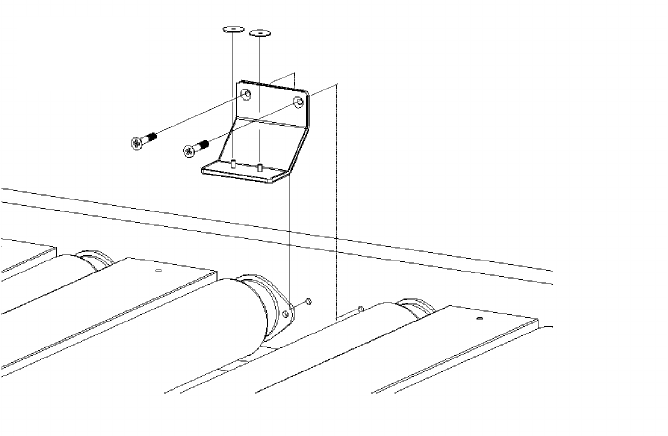
then wipe clean with alcohol.
5. Place the Reader Bracket in position with (2) mounting bolts.
Figure 2-3 Reader Bracket and Mounting Bolts
6. Attach alock washer and nut on each bolt and hand tighten.
7. Attach the Bracket Mounting Fixture to the Reader Bracket, using
Retaining Bolt “A” (m10 -1.5 carriage bolt).
ULD Reader Installation
ULD Reader InstallationULD Reader Installation
ULD Reader Installation
2-6
2-62-6
2-6 ULD Reader Installation Guide
ULD Reader Installation GuideULD Reader Installation Guide
ULD Reader Installation Guide
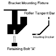
Figure 2-4 Bracket Mounting Fixture
8. Align the Reader Bracket until the Roller Tangent Bar indicates proper
positioning with the roller tangent.
9. Tighten the mounting bolts to secure the Reader Bracket.
10. Apply three spot welds to the Reader Bracket.
11. Remove Retaining Bolt “A”.
Refer to Figure 2-4.
12. Remove the Bracket Mounting Fixture.
13. Repeat preceding steps for the opposing bracket.

ULD Reader Installation
ULD Reader InstallationULD Reader Installation
ULD Reader Installation
ULD Reader Installation Guide
ULD Reader Installation GuideULD Reader Installation Guide
ULD Reader Installation Guide 2-7
2-72-7
2-7
Reader Bracket Installation for Workstations
This activity consists of removing the existing bracket and installing the
Reader Bracket (bracket) at Workstations 1through 12.
You must perform the procedure, “Removing Deck Plates” on page 2-4
before performing this procedure.
Note: The existing brackets at the Workstation locations (1 through 12)
are welded into place.
•Toremove the existing bracket and install the Reader Bracket for
Workstations 1through 12:
1. Remove the existing brackets using an acetylene torch or grinder operated
by aqualified on-site welder.
Heat Shields must be placed between the mounting bracket and the
bearings that support the rollers, to avoid Roller Bearing damage.
2. After the existing bracket has been removed, inspect the bracket
mounting holes for any dimension and concentricity anomalies.
3. If required, hand-grind the bracket mounting surface smooth.
4. Clean the bracket mounting surface and mounting holes with Xylene,
then wipe with alcohol.
5. Place the Reader Bracket in position with two (2) mounting bolts.
ULD Reader Installation
ULD Reader InstallationULD Reader Installation
ULD Reader Installation
2-8
2-82-8
2-8 ULD Reader Installation Guide
ULD Reader Installation GuideULD Reader Installation Guide
ULD Reader Installation Guide
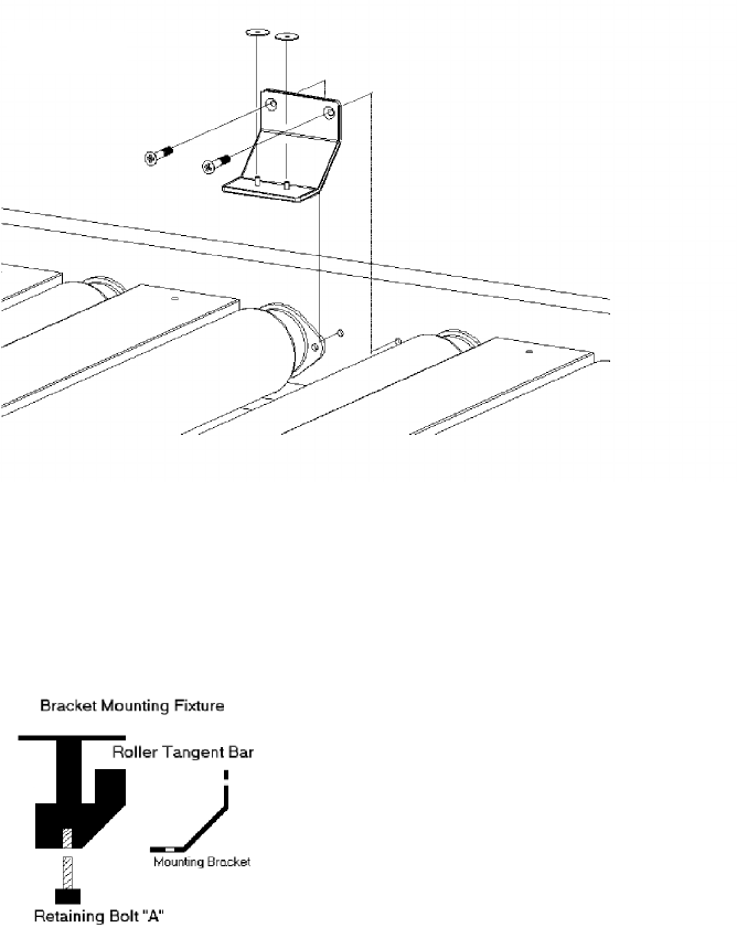
Figure 2-5 Reader Bracket and Mounting Bolts
6. Place alock washer on each bolt.
7. Place anut on each bolt and hand-tighten.
8. Attach the Bracket Mounting Fixture onto the Reader Bracket, using the
Retaining Bolt “A” (m10 -1.5 carriage bolt).
Figure 2-6 Bracket Mounting Fixture
9. Align the Reader Bracket until the Roller Tangent Bar indicates proper
positioning with roller tangent.
10. Tighten the mounting bolts.
11. Apply three (3) spot welds to the bracket.
ULD Reader Installation
ULD Reader InstallationULD Reader Installation
ULD Reader Installation
ULD Reader Installation Guide
ULD Reader Installation GuideULD Reader Installation Guide
ULD Reader Installation Guide 2-9
2-92-9
2-9
12. Remove the Retaining Bolt “A”.
Refer to Figure 2-6.
13. Remove the Bracket Mounting Fixture.
14. Repeat the preceding steps for the opposing bracket.
ULD Reader Installation
ULD Reader InstallationULD Reader Installation
ULD Reader Installation
2-10
2-102-10
2-10 ULD Reader Installation Guide
ULD Reader Installation GuideULD Reader Installation Guide
ULD Reader Installation Guide
Reader Installation
Reader installation consists of temporarily installing aReader Housing to
ensure proper fit, and installing the Reader.
Temporary Reader Housing Installation
You need to temporarily install aReader Housing to verify proper fit before
you begin the formal process of installation.
•Totemporarily install the Reader:
1. Set the sample Reader Housing in place and check for proper alignment.
2. Remove the sample Reader Housing.
3. Permanently weld the Reader Bracket.
4. Paint the Reader Bracket to protect it from the elements.
5. Replace the sample Reader Housing with the new temporary deck plate.
Final Reader Installation
Preliminary Requirements
Before actually installing the Reader, run the data communication and
230VAC power cables from the control console to the required location under
the Reader housing.
Place aprotective tarp and work blocks next to the prepared Reader location
cell, and place the Reader on two 2x4 wooden work blocks with the top (Dock
Plate) facing up.
Installing the Reader
•Toinstall the Reader:
1. Remove one (1) m10 screw from each end of the Reader’s Deck Plate.
2. Attach aLifting Handle to each of the Reader’s threaded holes, by
inserting and turning the matching threaded end of the Lifting Tool until
snug.
ULD Reader Installation
ULD Reader InstallationULD Reader Installation
ULD Reader Installation
ULD Reader Installation Guide
ULD Reader Installation GuideULD Reader Installation Guide
ULD Reader Installation Guide 2-11
2-112-11
2-11
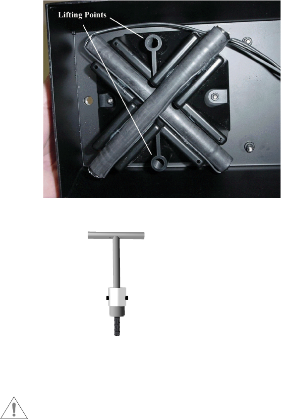
Figure 2-7 on page 2-11 illustrates the lifting points where the lifting
tools are attached to the Reader. Figure 2-8 on page 2-11 is an example
of asingle Lifting Handle tool.
Figure 2-7 Reader Lifting Points
Figure 2-8 Lifting Tool (Handles)
3. Lift the Reader and carefully lower it onto the mounting Reader Brackets.
Athird technician needs to be in aposition to guide the Reader to the
bracket pins. These pins are at the Access Panel end of the Reader. The
mounting holes at this end of the Reader are NOT slotted.
ULD Reader Installation
ULD Reader InstallationULD Reader Installation
ULD Reader Installation
2-12
2-122-12
2-12 ULD Reader Installation Guide
ULD Reader Installation GuideULD Reader Installation Guide
ULD Reader Installation Guide
4. Attach the Reader to the Reader Brackets using Retaining Bolts “A” (see
Figure 2-6 on page 2-8).
5. Check for Reader distance from the roller tangent (0.480 -0.5”) at both
ends of the Reader.
6. Check for any interference.
7. Remove Retaining Bolts “A” from both brackets.
8. Remove the Reader, and place it with the top (Dock Plate) facing down
onto the two 2x4 wooden work blocks for communication and power
connection, pulling two meters of cable slack from the pit.
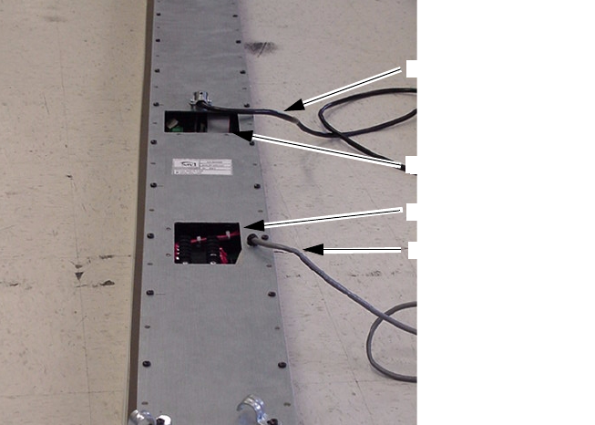
9. Remove the Terminal Access Panels for power and communication on the
bottom of the Reader.
Figure 2-9 shows the Reader face down with its access panels for power
and communication.
Figure 2-9 Terminal Access Panels
10. With power OFF to both the communication and power cables leading to
the Reader, use aMulti-meter to perform acontinuity check.
11. Attach the 230VAC wire connections to the terminal block, as shown in
Figure 2-10.
Power Access
Power Cable
Communication Access
Communication Cable
ULD Reader Installation
ULD Reader InstallationULD Reader Installation
ULD Reader Installation
ULD Reader Installation Guide
ULD Reader Installation GuideULD Reader Installation Guide
ULD Reader Installation Guide 2-13
2-132-13
2-13
Figure 2-10 Power Terminals
Terminal connections are as follows:
White (WHT) or Blue -Term # 1
Green (GRN) -Attached to the chassis lug.
Black (BLK) or Brown -Term # 3
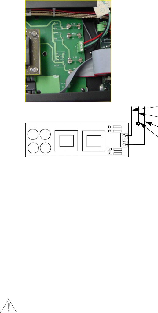
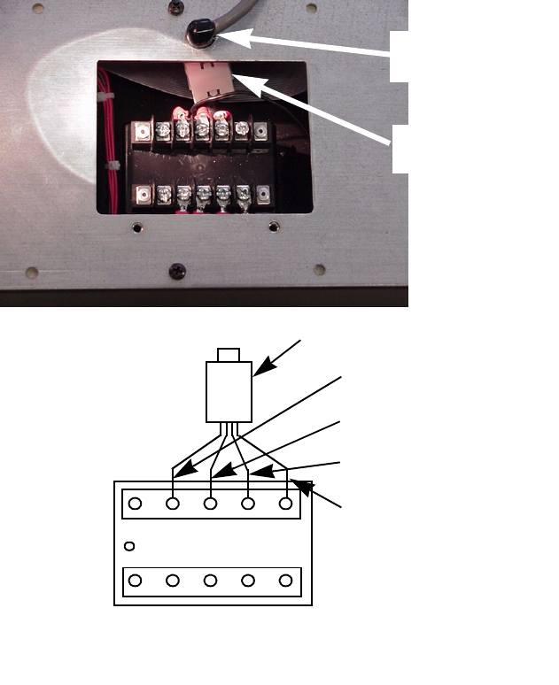
12. Attach the communication cable to the terminal block (and PC), as
described in the steps below and shown in Figure 2-11, Figure 2-12, and
Figure 2-13.
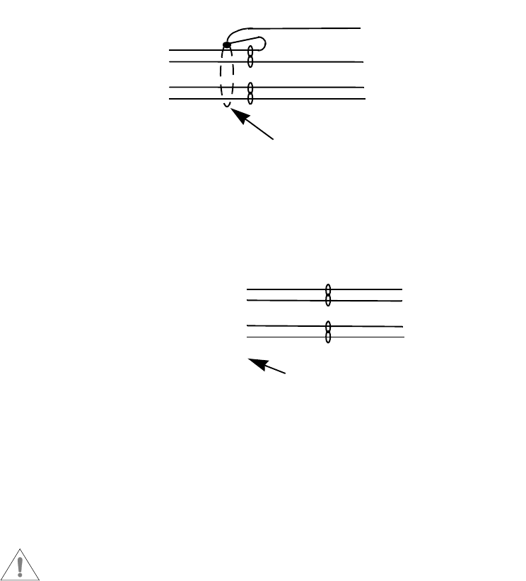
•Insertthe communication cable through the opening in the bottom
cover.
•Clampthe Ferrite onto the communication cable.
The ferrite must be installed as described to meet FCC requirements.
Chassis Lug
WHT
GRN
BLK
ULD Reader Installation
ULD Reader InstallationULD Reader Installation
ULD Reader Installation
2-14
2-142-14
2-14 ULD Reader Installation Guide
ULD Reader Installation GuideULD Reader Installation Guide
ULD Reader Installation Guide
• Connect the cable leads to the terminal block.
•Removethe excess cable from the compartment interior.
•Attachthe strain relief and press into the housing.
Figure 2-11Communication Terminals
Snap-on
Ferrite
Strain
Relief
L4 L3 L2 L1 GND
Transient
Side
RX -Data In (WHT)
TX -Data Out (RED)
Program (BLK)
GND (BLK)
Snap-on Ferrite
To Female DB-9
Protected
Side
ULD Reader Installation
ULD Reader InstallationULD Reader Installation
ULD Reader Installation
ULD Reader Installation Guide
ULD Reader Installation GuideULD Reader Installation Guide
ULD Reader Installation Guide 2-15
2-152-15
2-15
Figure 2-12 Transient Suppressor Connection
Figure 2-13 PC Connection
13. Secure the cables to the Strain Relief metal loops, located on the bottom
of the Reader.
14. Reattach the Terminal Access Panel on the bottom of the Reader.
15. Turn the Reader with the top (Dock Plate) facing up.
Athird technician needs to be in aposition to guide the Reader to the
Bracket pins and help manage the cables at the Access Panel end of the
Reader.
16. Using the lifting handles, lower the Reader onto the permanently welded
Reader Brackets.
17. Secure the Reader to the Reader Brackets using Retaining Bolts “A”.
To PC
BLK -GND
WHT -L3
BLK -L1
RED -L2
Shield
To ULD Reader
BLK - 8
RED - 2
BLK - 5
WHT - 3
DB9
Female
ULD Reader Installation
ULD Reader InstallationULD Reader Installation
ULD Reader Installation
2-16
2-162-16
2-16 ULD Reader Installation Guide
ULD Reader Installation GuideULD Reader Installation Guide
ULD Reader Installation Guide
Required Installation Tools
This section provides alisting of the required tools to perform the installation
tasks outlined in this chapter. These tools include:
• Acetylene Torch (on-site access)
• Adhesives
•ArcWelder
• Phillips Screwdriver Set
• Standard Screwdriver Set
• Double Face Tape
• Soldering Gun/Pencil
•Solder
•HandGrinder w/Misc. Wheels
•SocketWrench Set (metric)
•ViceGrips
•CrescentWrench Set
• Box/Open End Wrench Set
• Extension Cords
•QuadPower Box
•WireCutters/Strippers
• Multi-Meter
•TerminalLug Crimper
•AMPDB-9 Connector Crimper
•MetricTape Measure
•2ea. Mounting Bracket Alignment Fixtures
•4ea. Reader Lifting Tools
ULD Reader Installation
ULD Reader InstallationULD Reader Installation
ULD Reader Installation
ULD Reader Installation Guide
ULD Reader Installation GuideULD Reader Installation Guide
ULD Reader Installation Guide 2-17
2-172-17
2-17
Installation Materials
The following materials are required to perform the installation tasks:
•26ea. Temporary Deck Plates
•52ea. Mounting Brackets
•104ea.(3/8 in. diameter) Nuts, Bolts and Washers
•A/R,AC Power Cable
•A/R,Data Cable
•26ea. DB-9 Female Connector
•A/R,Misc. Wire Lugs/Connectors
•26ea. ULD Readers
ULD Reader Installation
ULD Reader InstallationULD Reader Installation
ULD Reader Installation
2-18
2-182-18
2-18 ULD Reader Installation Guide
ULD Reader Installation GuideULD Reader Installation Guide
ULD Reader Installation Guide
Reader Locations
This section consists of photographs illustrating Reader locations, including:
• TTTV 1through 3onpage 2-18
•BV1and 2onpage 2-19
• ETV 1through 3onpage 2-20
• Workstations 1through 12 on page 2-21
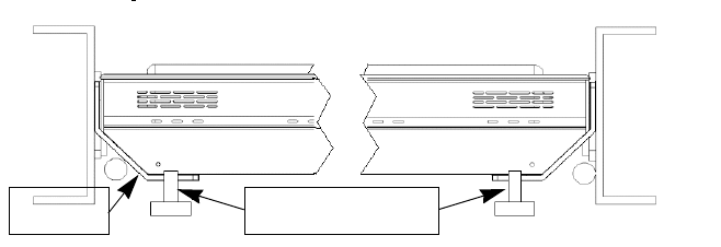
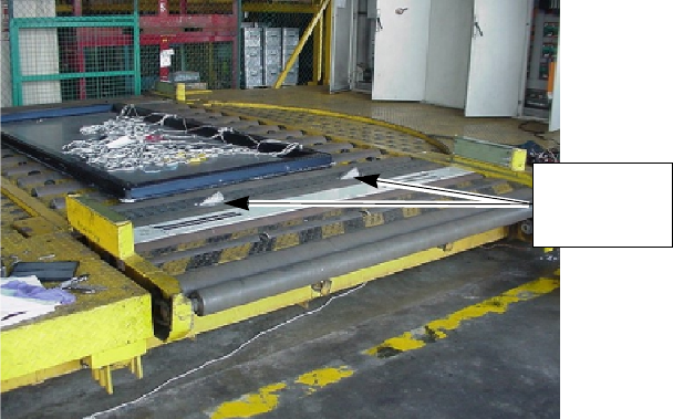
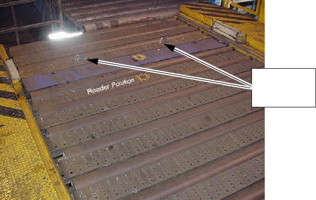
TTTV 1 through 3
Each TTTV location requires two Readers. AReader is to be placed at the
front of the Stops on both the airside and the landside.
Figure 2-14 TTV 1 - 3 Location
Stops
ULD Reader Installation
ULD Reader InstallationULD Reader Installation
ULD Reader Installation
ULD Reader Installation Guide
ULD Reader Installation GuideULD Reader Installation Guide
ULD Reader Installation Guide 2-19
2-192-19
2-19
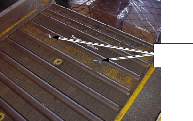
BV 1 and 2
Each BV location requires one Reader.
Figure 2-15 BV 1 and 2 Location
Stops
ULD Reader Installation
ULD Reader InstallationULD Reader Installation
ULD Reader Installation
2-20
2-202-20
2-20 ULD Reader Installation Guide
ULD Reader Installation GuideULD Reader Installation Guide
ULD Reader Installation Guide
ETV 1 through 3
Each ETV location requires two Readers. AReader is to be placed at the front
of the stops on both the airside and the landside.
Figure 2-16 ETV 1 - 3 Location
Stops
ULD Reader Installation
ULD Reader InstallationULD Reader Installation
ULD Reader Installation
ULD Reader Installation Guide
ULD Reader Installation GuideULD Reader Installation Guide
ULD Reader Installation Guide 2-21
2-212-21
2-21
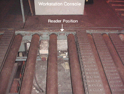
Workstations 1 through 12
Each Workstation location requires one Reader.
Figure 2-17 Workstation 1 - 12 Location

ULD Reader Installation
ULD Reader InstallationULD Reader Installation
ULD Reader Installation
2-22
2-222-22
2-22 ULD Reader Installation Guide
ULD Reader Installation GuideULD Reader Installation Guide
ULD Reader Installation Guide
Installation Sheets
The following installation sheets consist of hardware diagrams for the
following locations:
• TTTV 1, Level 1onpage 2-23
• TTTV 2, Level 1onpage 2-24
• TTTV 3, Level 1onpage 2-25
•BV1, Level 2onpage 2-26
•BV2, Level 5onpage 2-27
• ETV 1, Level 1onpage 2-28
• ETV 2, Level 1onpage 2-29
• ETV 3, Level 1onpage 2-30
• Workstation 1 - 12, MCP 1, Level 1onpage 2-31
These installation sheets also consist of sign-off fields to be filled out and
signed when work is complete.
Installation sheets must be completed and signed by the Installation
Supervisor.

ULD Reader Installation
ULD Reader InstallationULD Reader Installation
ULD Reader Installation
ULD Reader Installation Guide
ULD Reader Installation GuideULD Reader Installation Guide
ULD Reader Installation Guide 2-23
2-232-23
2-23
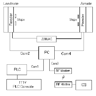
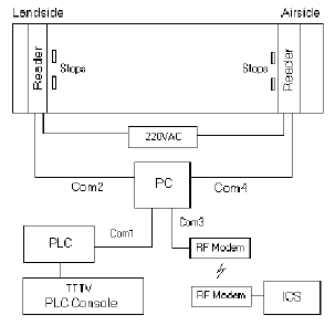
TTTV 1, Level 1
The Reader is positioned in front of the stops on the airside and the landside.
This location requires:
•2Readers
•4Brackets
Figure 2-18 TTTV1, Level 1 Hardware Diagram
Check list:
Station test:
Savi Supervisor sign-off:
Notes:
ULD Reader Installation
ULD Reader InstallationULD Reader Installation
ULD Reader Installation
2-24
2-242-24
2-24 ULD Reader Installation Guide
ULD Reader Installation GuideULD Reader Installation Guide
ULD Reader Installation Guide
TTTV 2, Level 1
The Reader is positioned in front of the stops on the airside and the landside.
This location requires:
•2Readers
•4Brackets
Figure 2-19 TTTV 2, Level 1 Hardware Diagram
Check list:
Station test:
Savi Supervisor sign-off:
Notes:
ULD Reader Installation
ULD Reader InstallationULD Reader Installation
ULD Reader Installation
ULD Reader Installation Guide
ULD Reader Installation GuideULD Reader Installation Guide
ULD Reader Installation Guide 2-25
2-252-25
2-25
TTTV 3, Level 1
The Reader is positioned in front of the stops on the airside and the landside.
This location requires:
•2Readers
•4Brackets
Figure 2-20 TTTV 3, Level 1 Hardware Diagram
Check list:
Station test:
Savi Supervisor sign-off:
Notes:
ULD Reader Installation
ULD Reader InstallationULD Reader Installation
ULD Reader Installation
2-26
2-262-26
2-26 ULD Reader Installation Guide
ULD Reader Installation GuideULD Reader Installation Guide
ULD Reader Installation Guide
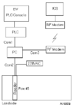
BV 1, Level 2
This location requires:
•1Reader
•2Brackets
Figure 2-21 BV 1, Level 2 Hardware Diagram
Check list:
Station test:
Savi Supervisor sign-off:
Notes:
ULD Reader Installation
ULD Reader InstallationULD Reader Installation
ULD Reader Installation
ULD Reader Installation Guide
ULD Reader Installation GuideULD Reader Installation Guide
ULD Reader Installation Guide 2-27
2-272-27
2-27
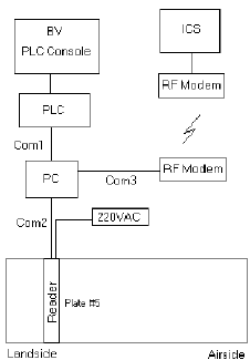
BV 2, Level 5
This location requires:
•1Reader
•2Brackets
Figure 2-22 BV 2, Level 1 Hardware Diagram
Check list:
Station test:
Savi Supervisor sign-off:
Notes:

ULD Reader Installation
ULD Reader InstallationULD Reader Installation
ULD Reader Installation
2-28
2-282-28
2-28 ULD Reader Installation Guide
ULD Reader Installation GuideULD Reader Installation Guide
ULD Reader Installation Guide
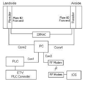
ETV 1, Level 1
The Reader is positioned in front of the stops on the airside and the landside.
This location requires:
•2Readers
•4Brackets
Figure 2-23 ETV 1, Level 1 Hardware Diagram
Check list:
Station test:
Savi Supervisor sign-off:
Notes:

ULD Reader Installation
ULD Reader InstallationULD Reader Installation
ULD Reader Installation
ULD Reader Installation Guide
ULD Reader Installation GuideULD Reader Installation Guide
ULD Reader Installation Guide 2-29
2-292-29
2-29
ETV 2, Level 1
The Reader is positioned in front of the stops on the airside and the landside.
This location requires:
•2Readers
•4Brackets
Figure 2-24 ETV 2, Level 1 Hardware Diagram
Check list:
Station test:
Savi Supervisor sign-off:
Notes:
ULD Reader Installation
ULD Reader InstallationULD Reader Installation
ULD Reader Installation
2-30
2-302-30
2-30 ULD Reader Installation Guide
ULD Reader Installation GuideULD Reader Installation Guide
ULD Reader Installation Guide
ETV 3, Level 1
The Reader is positioned in front of the stops on the airside and the landside.
This location requires:
•2Readers
•4Brackets
Figure 2-25 ETV 3, Level 1 Hardware Diagram
Check list:
Station test:
Savi Supervisor sign-off:
Notes:
ULD Reader Installation
ULD Reader InstallationULD Reader Installation
ULD Reader Installation
ULD Reader Installation Guide
ULD Reader Installation GuideULD Reader Installation Guide
ULD Reader Installation Guide 2-31
2-312-31
2-31
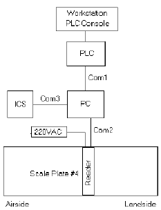
Workstation 1 - 12, MCP 1, Level 1
The Reader is positioned in front of the stops on the airside and the landside.
This location requires:
•1Reader
•2Brackets
Figure 2-26 Workstation 1-12, MCP 1, Level 1 Hardware Diagram
Check list:
Station test:
Savi Supervisor sign-off:
Notes:
ULD Reader Installation
ULD Reader InstallationULD Reader Installation
ULD Reader Installation
2-32
2-322-32
2-32 ULD Reader Installation Guide
ULD Reader Installation GuideULD Reader Installation Guide
ULD Reader Installation Guide
ULD Reader Installation Guide
ULD Reader Installation GuideULD Reader Installation Guide
ULD Reader Installation Guide IX-1
IX-1IX-1
IX-1
Index 1
A-B
access panels, terminal 2-12
attachment
communication cable 2-13
power connections 2-12
Bracket
removal and installation 2-4,2-7
ULD Reader 2-2
Bracket Mounting Fixture 2-8
C
communication cable
attachment 2-13
D
deck plates
removing 2-4
F-G
Guide Conventions iv
help
technical support v
H-I
installation
Bracket 2-4,2-7
materials 2-17
Reader 2-10
temporary, Reader 2-10
tools 2-16
L
location
BV 1, Level 22-26
BV 2, Level 52-27
EVT 1, Level 12-28
EVT 2, Level 12-29
EVT 3, Level 12-30
Reader 2-18
TTTV 1, Level 12-23
TTTV 2, Level 12-24
TTTV 3, Level 12-25
Workstation 1 - 12, MCP 1, Level 12-31
M
materials
installation 2-17
mechanical description 2-2
N
nstallation 2-10
O-P
power connections
attachment 2-12
R
Reader
temporary installation 2-10
Reader installation 2-10
Reader locations 2-18
ETV 1through 32-20
TTTV 1through 32-18
Workstations 1through 12 2-21
removal
Bracket 2-4,2-7
removing deck plates 2-4
S
Savi Technical Support v