Schindler elevators PCRTWN4 Card reader module PCR-TWN4 User Manual PCR with Elatec TWN4 006x
Schindler elevators Ltd Card reader module PCR-TWN4 PCR with Elatec TWN4 006x
UserManual.wiki
>
Schindler elevators
>
PCRTWN4 User Manual
Users manual
Navigation menu
Upload a User Manual
Namespaces
Wiki Guide
HTML
PDF
Info
Views
User Manual
Discussion / Help
Navigation
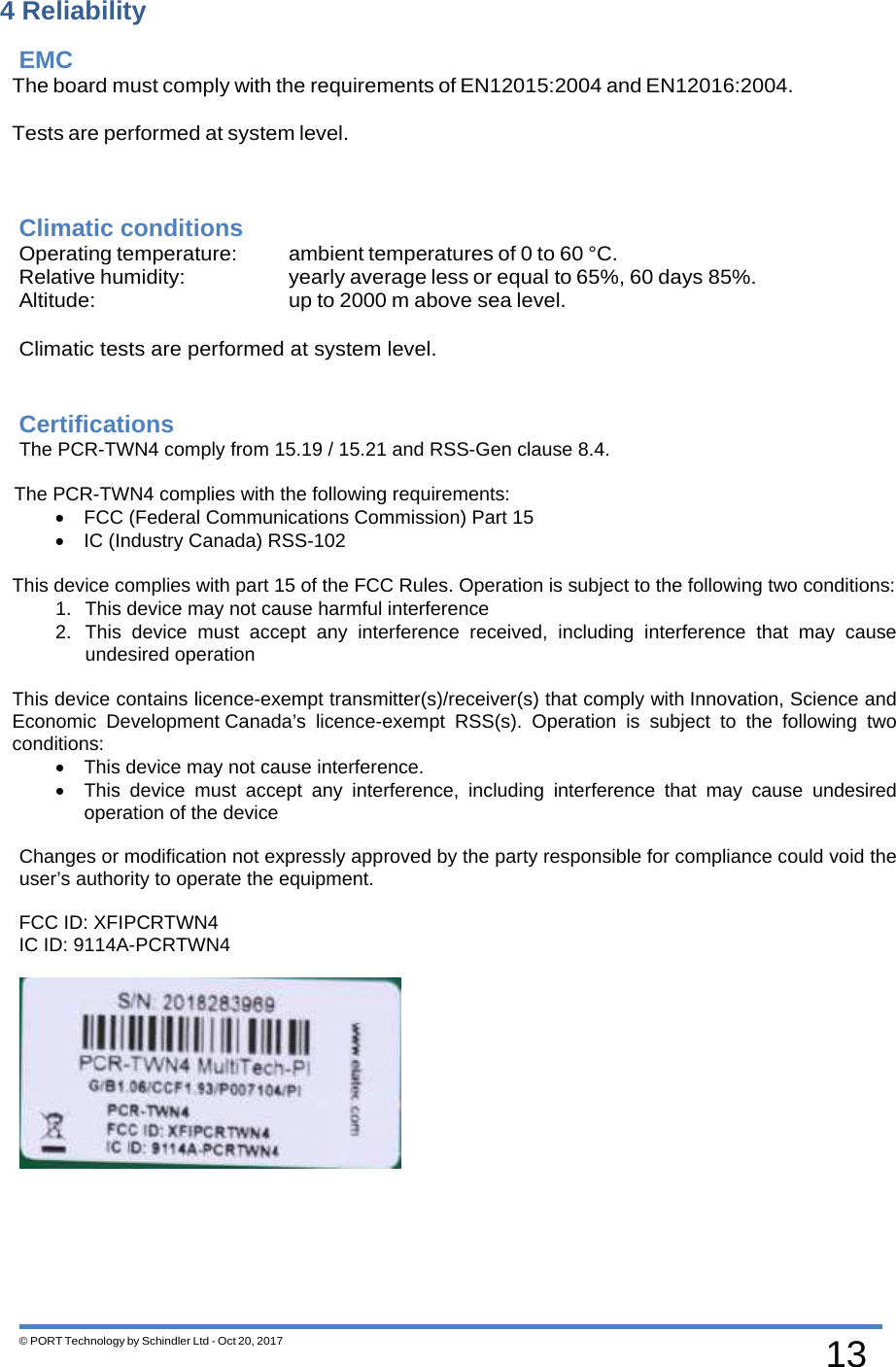
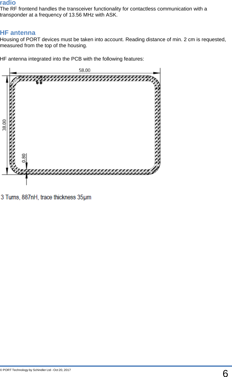
![3 © PORT Technology by Schindler Ltd - Oct 20, 2017 Scope The PCR-TWN4 board implements the following main parts and functions: USB interface to host Radar interface (similar PCRI) I/O interface (similar PCRI): - 2 inputs - 2 outputs Wiegand Output (similar NFCUSB) 4 x RGB LED’s Compatibility The PCR-TWN4 is hardware compatible with PCRI resp. NFCUSB. General overview References REF[1] data sheet TWN4 reader module (www.elatec-rfid.com) REF[2] data sheet K-LC1a radar transceiver (www.rfbeam.ch) REF[3] data sheet JRC radar transceiver PORT PCR-TWN4 + HF antenna Elevator Controller USB Host LEP, MLEP, WLEP ... TWN4](https://usermanual.wiki/Schindler-elevators/PCRTWN4/User-Guide-4110220-Page-3.png)
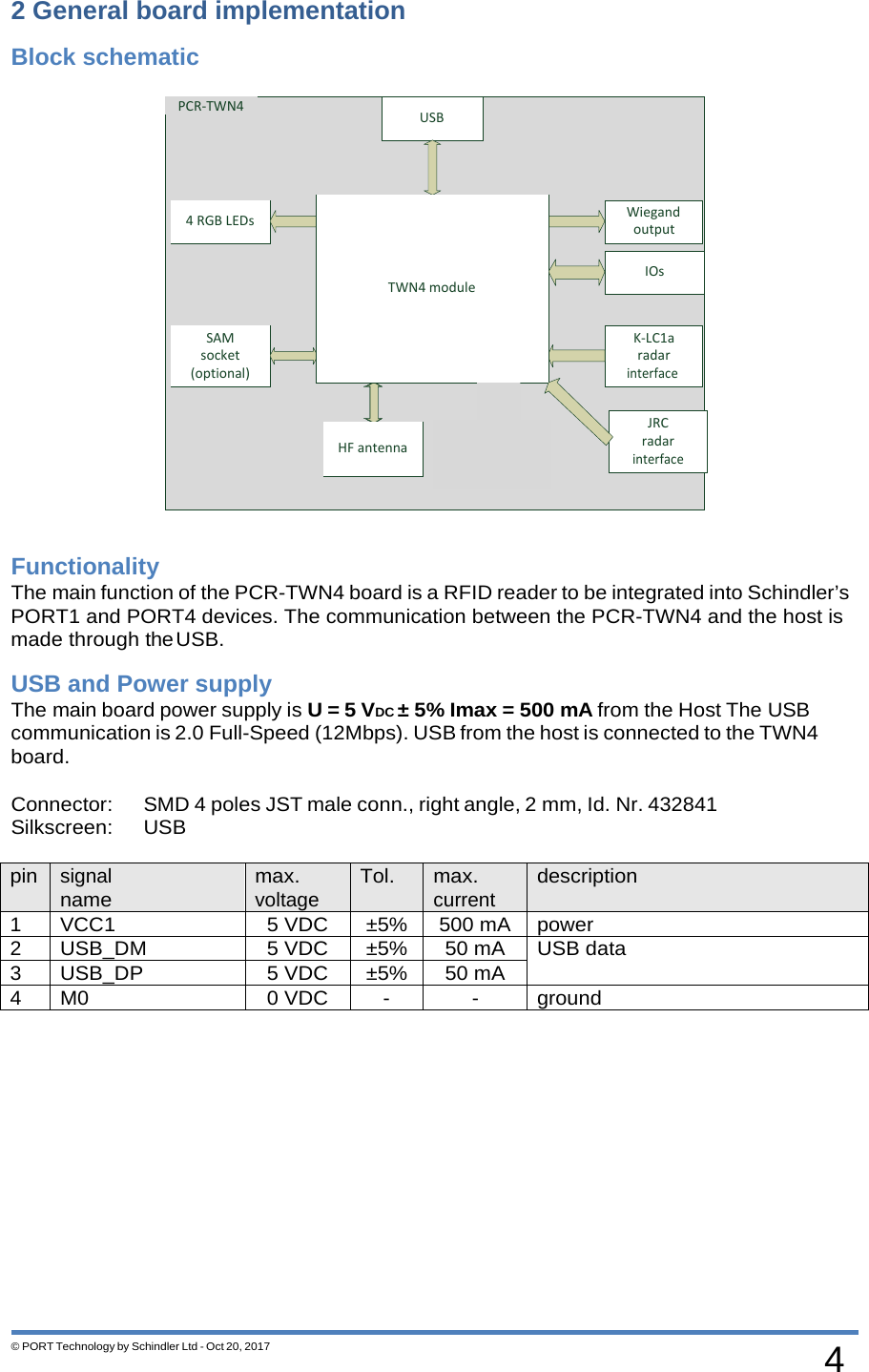
![5 © PORT Technology by Schindler Ltd - Oct 20, 2017 TWN4 module As a default the Mifare NFC Standard module should be applied. See also REF[1]](https://usermanual.wiki/Schindler-elevators/PCRTWN4/User-Guide-4110220-Page-5.png)
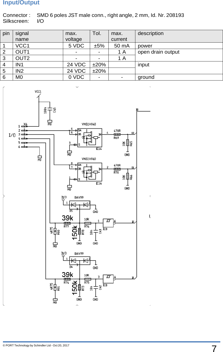
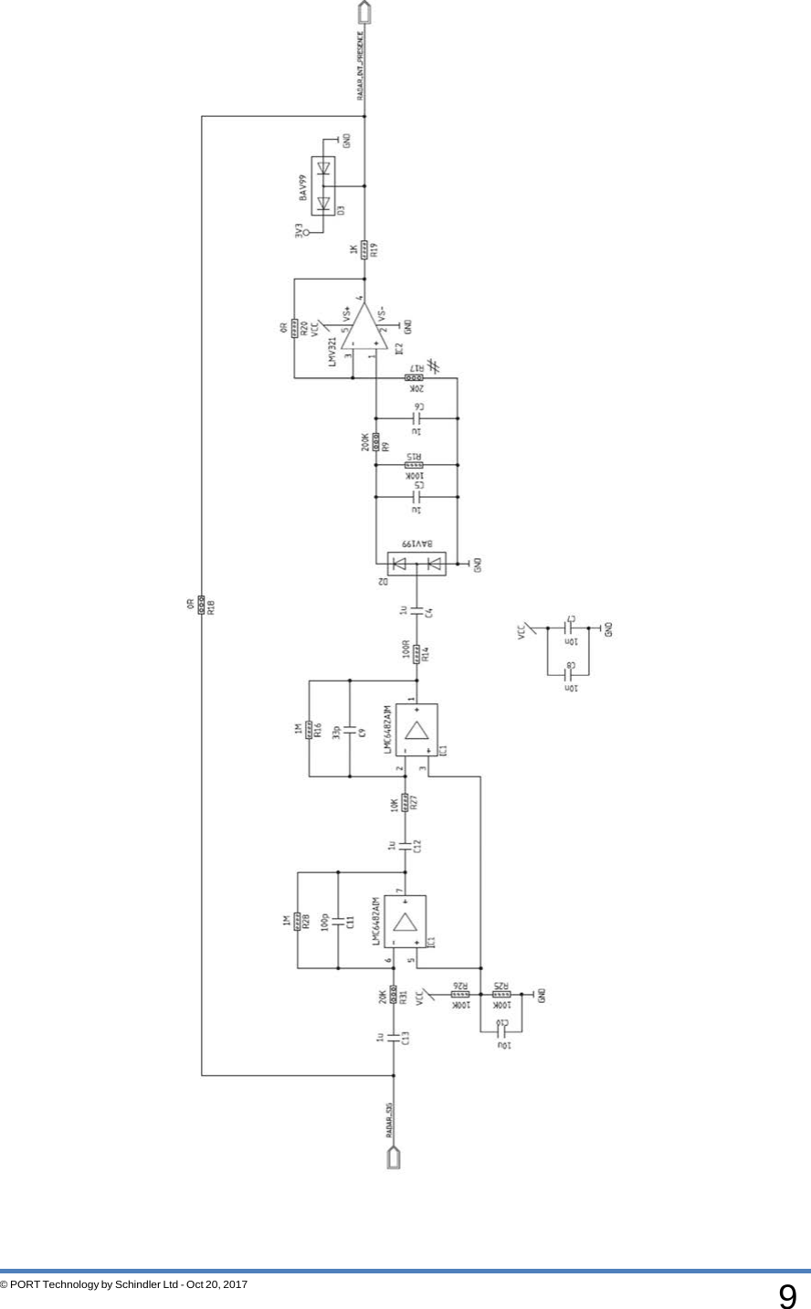
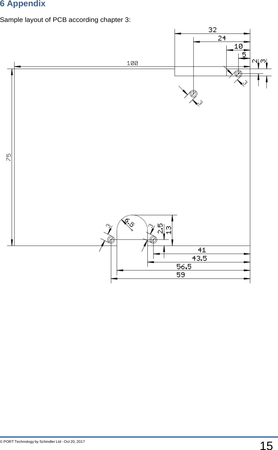
![8 © PORT Technology by Schindler Ltd - Oct 20, 2017 Wiegand output Connector: SMD 3 poles JST male conn., right angle, 2 mm, Id. Nr. 59902178 Silkscreen: W_OUT pin signal name max. voltage Tol. max. current description 1 DATA1 12 V 20 mA Wiegand Data 1 2 DATA0 12 V 20 mA Wiegand Data 0 3 GND - - - K-LC1A radar interface Connector: SMD 2x3 poles pass through conn., low profile, 2.54 mm, Id. Nr. 208176 Silkscreen: RADAR pin signal name max. voltage Tol. max. current description 1 GND 0 VDC - - ground 2 nc - - - 3 RADAR_SIG - - - Signal direct from the radar see REF [1] 4 nc - - 5 VCC 5 VDC ±5% 50 mA power 6 nc - - - sample cicuit below:](https://usermanual.wiki/Schindler-elevators/PCRTWN4/User-Guide-4110220-Page-8.png)