Schindler elevators PCRTWN4 Card reader module PCR-TWN4 User Manual PCR with Elatec TWN4 006x
Schindler elevators Ltd Card reader module PCR-TWN4 PCR with Elatec TWN4 006x
Users manual

1
© PORT Technology by Schindler Ltd - Oct 20, 2017
RFID Reader for PORT
PCR-TWN4
Contents
1
Introduction
......................................................................................................................................
2
Scope
...............................................................................................................................................
3
Compatibility
....................................................................................................................................
3
General overview
............................................................................................................................
3
References
......................................................................................................................................
3
2
General board implementation
......................................................................................................
4
Block schematic
..............................................................................................................................
4
Functionality
....................................................................................................................................
4
USB and Power supply
..................................................................................................................
4
TWN4 module
.................................................................................................................................
5
radio
..................................................................................................................................................
6
HF antenna
......................................................................................................................................
6
Input/Output
.....................................................................................................................................
7
Wiegand output
...............................................................................................................................
8
K-LC1A radar interface
..................................................................................................................
8
JRC radar interface
......................................................................................................................
10
RGB LEDs
.....................................................................................................................................
11
SAM sockets
.................................................................................................................................
11
3
Mechanics
......................................................................................................................................
12
4
Reliability
........................................................................................................................................
13
EMC
................................................................................................................................................
13
Climatic conditions
.......................................................................................................................
13
Certifications
..................................................................................................................................
13
5
Document History
..........................................................................................................................
14
6
Appendix
.........................................................................................................................................
15
2
© PORT Technology by Schindler Ltd - Oct 20, 2017
1 Introduction
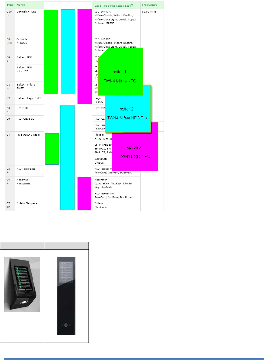
Currently PORT Technology by Schindler supports a wide range of readers (C0…C10). In
order to reduce the variety of card readers, we would like to introduce the TWN4 reader.
The target devices for PCR-TWN4 are PORT1 and PORT4. Both devices have a metal
housing that has an influence on the RFID readers.
PORT1
PORT4
3
© PORT Technology by Schindler Ltd - Oct 20, 2017
Scope
The PCR-TWN4 board implements the following main parts and functions:
USB interface to host
Radar interface (similar PCRI)
I/O interface (similar PCRI):
-
2 inputs
-
2 outputs
Wiegand Output (similar NFCUSB)
4 x RGB LED’s
Compatibility
The PCR-TWN4 is hardware compatible with PCRI resp. NFCUSB.
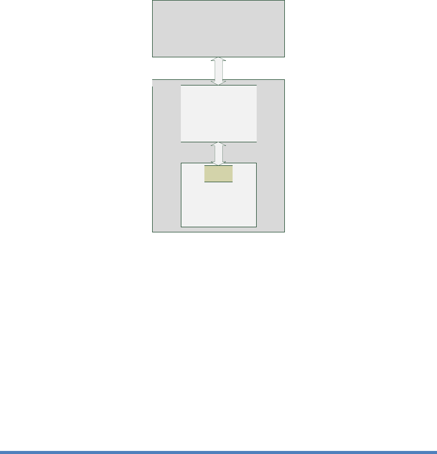
General overview
References
REF[1]
data sheet TWN4 reader module (www.elatec-rfid.com)
REF[2]
data sheet K-LC1a radar transceiver (www.rfbeam.ch)
REF[3]
data sheet JRC radar transceiver
PORT
PCR-TWN4
+
HF antenna
Elevator
Controller
USB Host
LEP, MLEP, WLEP ...
TWN4
4
© PORT Technology by Schindler Ltd - Oct 20, 2017
2 General board implementation
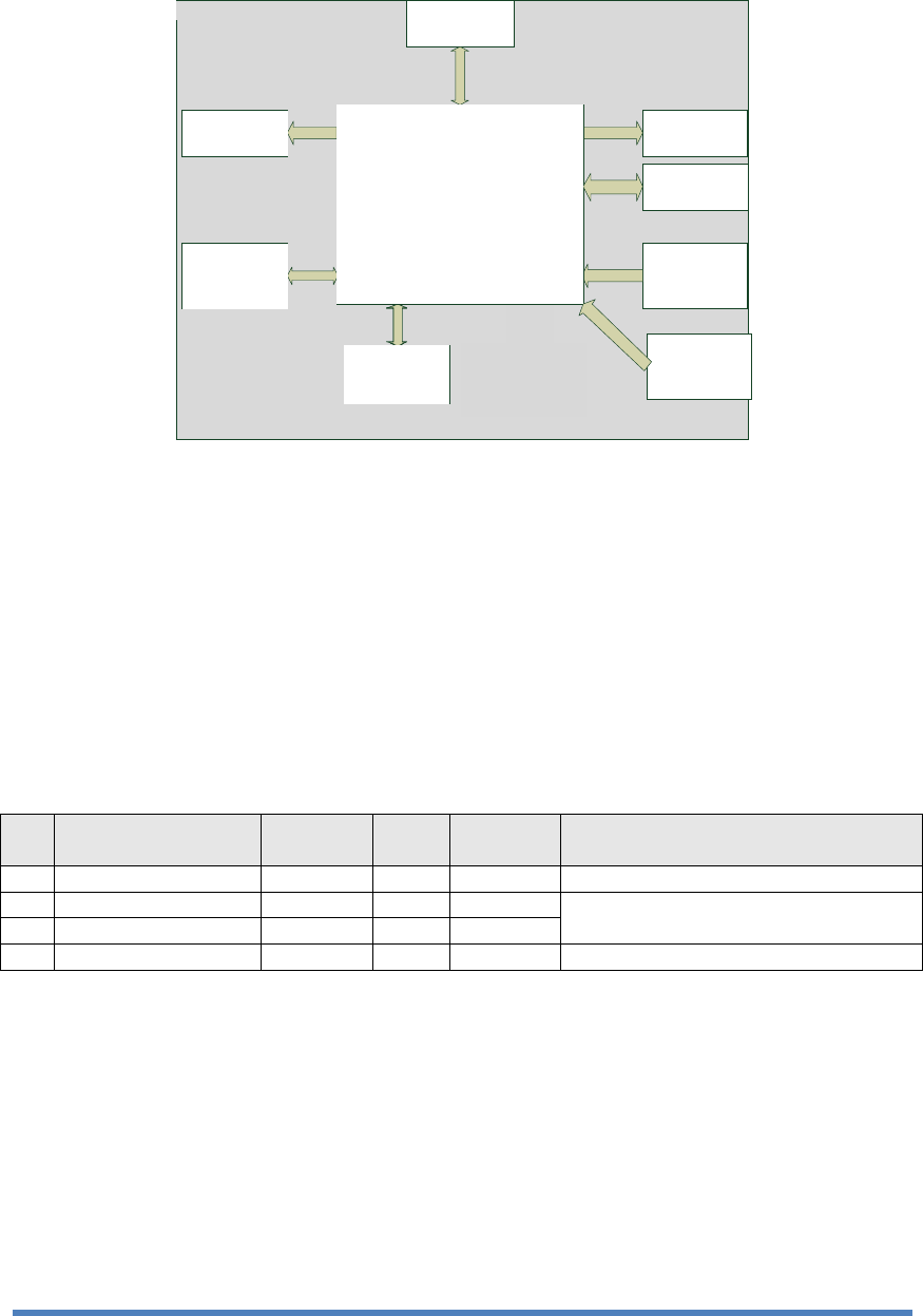
Block schematic
Functionality
The main function of the PCR-TWN4 board is a RFID reader to be integrated into Schindler’s
PORT1 and PORT4 devices. The communication between the PCR-TWN4 and the host is
made through the USB.
USB and Power supply
The main board power supply is
U = 5 V
DC
± 5% Imax = 500 mA
from the Host The USB
communication is 2.0 Full-Speed (12Mbps). USB from the host is connected to the TWN4
board.
Connector:
SMD 4 poles JST male conn., right angle, 2 mm, Id. Nr. 432841
Silkscreen:
USB
pin
signal
name
max.
voltage
Tol.
max.
current
description
1
VCC1
5 VDC
±5%
500 mA
power
2
USB_DM
5 VDC
±5%
50 mA
USB data
3
USB_DP
5 VDC
±5%
50 mA
4
M0
0 VDC
-
-
ground
USB
Wiegand
output
IOs
K-LC1a
radar
interface
JRC
radar
interface
PCR-TWN4
TWN4 module
4 RGB LEDs
SAM
socket
(optional)
HF antenna LF antenna
(optional)
5
© PORT Technology by Schindler Ltd - Oct 20, 2017
TWN4 module
As a default the Mifare NFC Standard module should be applied.
See also REF[1]
6
© PORT Technology by Schindler Ltd - Oct 20, 2017
radio
The RF frontend handles the transceiver functionality for contactless communication with a
transponder at a frequency of 13.56 MHz with ASK.
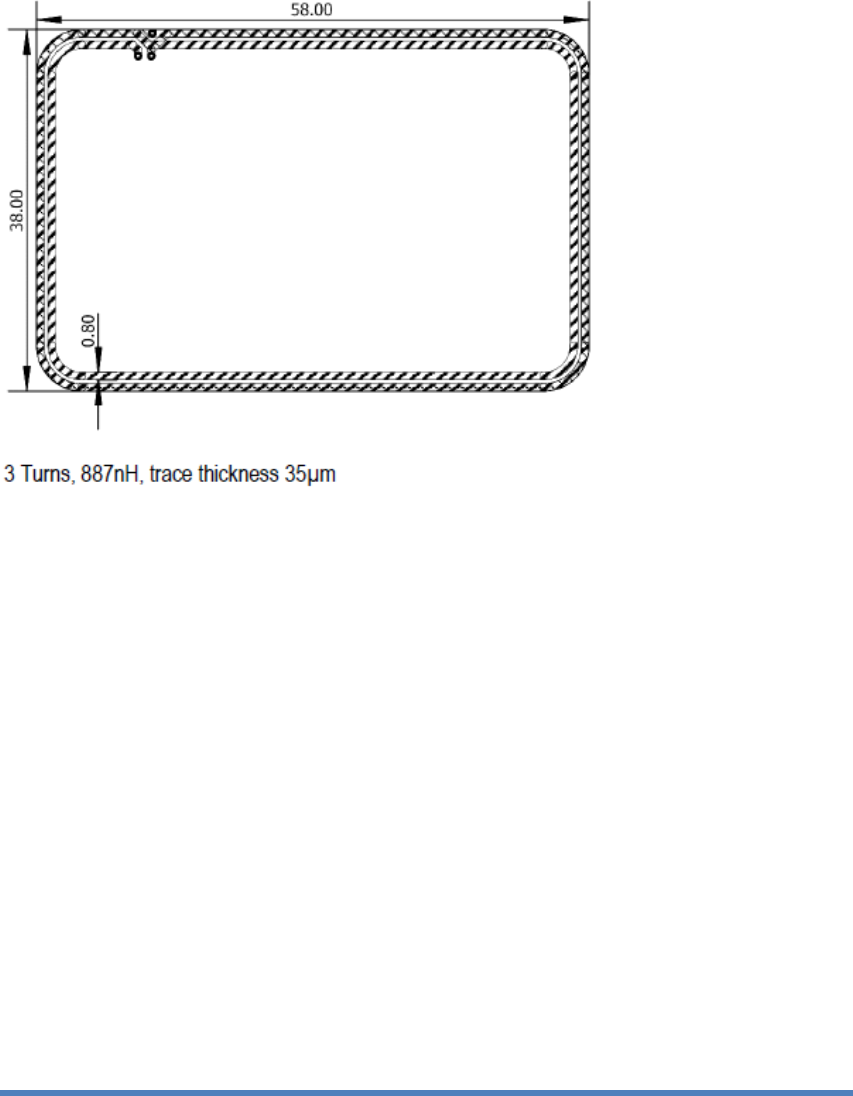
HF antenna
Housing of PORT devices must be taken into account. Reading distance of min. 2 cm is requested,
measured from the top of the housing.
HF antenna integrated into the PCB with the following features:
7
© PORT Technology by Schindler Ltd - Oct 20, 2017
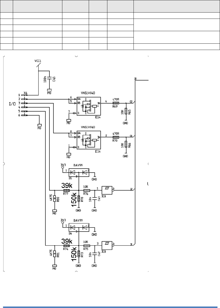
Input/Output
Connector :
SMD 6 poles JST male conn., right angle, 2 mm, Id. Nr. 208193
Silkscreen:
I/O
pin
signal
name
max.
voltage
Tol.
max.
current
description
1
VCC1
5 VDC
±5%
50 mA
power
2
OUT1
-
-
1 A
open drain output
3
OUT2
-
-
1 A
4
IN1
24 VDC
±20%
input
5
IN2
24 VDC
±20%
6
M0
0 VDC
-
-
ground
8
© PORT Technology by Schindler Ltd - Oct 20, 2017
Wiegand output
Connector:
SMD 3 poles JST male conn., right angle, 2 mm, Id. Nr. 59902178
Silkscreen:
W_OUT
pin
signal
name
max.
voltage
Tol.
max.
current
description
1
DATA1
12 V
20 mA
Wiegand Data 1
2
DATA0
12 V
20 mA
Wiegand Data 0
3
GND
-
-
-
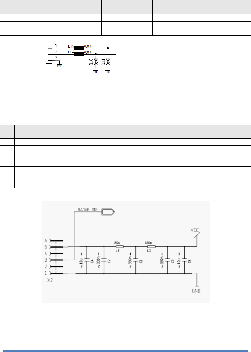
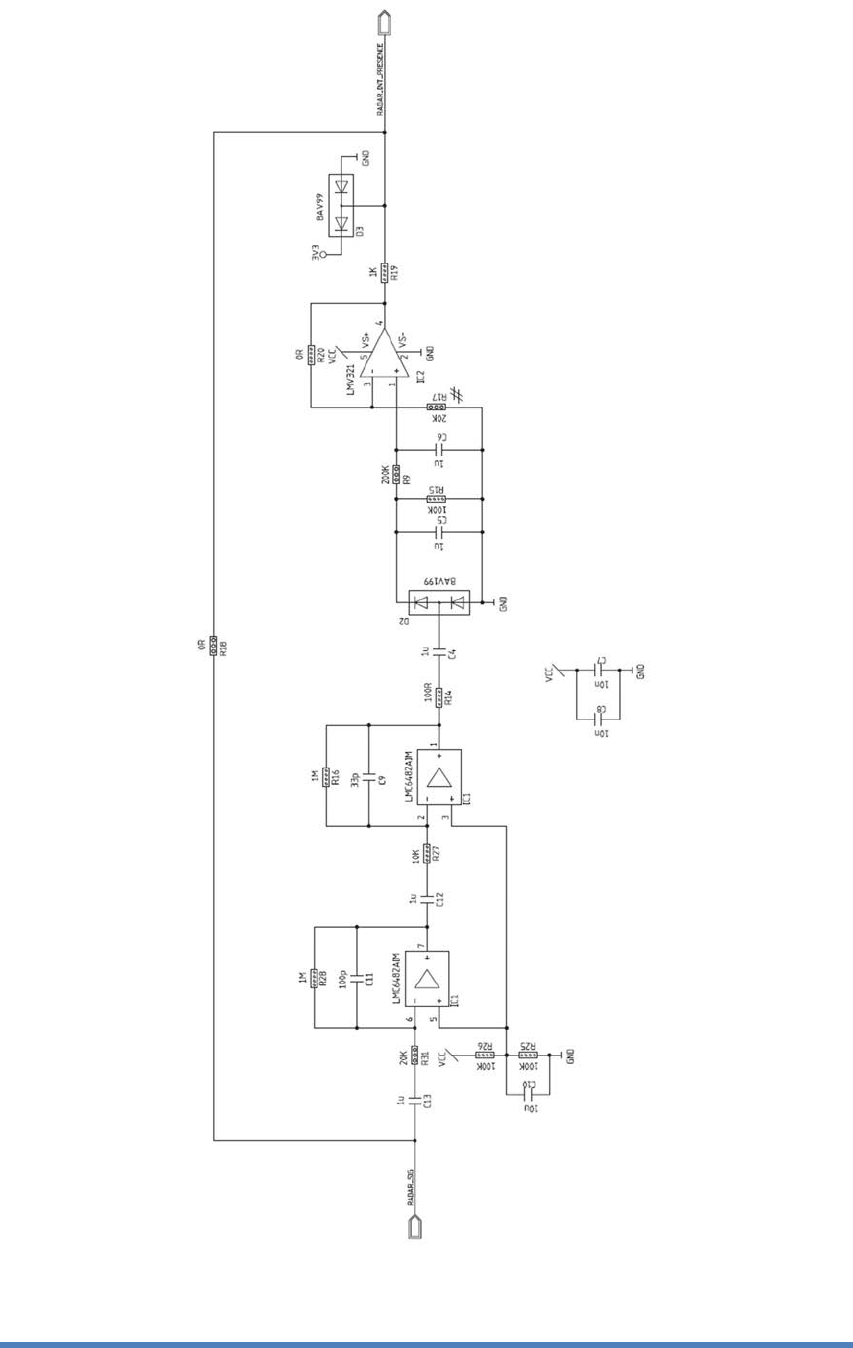
K-LC1A radar interface
Connector:
SMD 2x3 poles pass through conn., low profile, 2.54 mm, Id. Nr. 208176
Silkscreen:
RADAR
pin
signal
name
max.
voltage
Tol.
max.
current
description
1
GND
0 VDC
-
-
ground
2
nc
-
-
-
3
RADAR_SIG
-
-
-
Signal direct from the radar
see REF [1]
4
nc
-
-
5
VCC
5 VDC
±5%
50 mA
power
6
nc
-
-
-
sample cicuit below:
9
© PORT Technology by Schindler Ltd - Oct 20, 2017
10
© PORT Technology by Schindler Ltd - Oct 20, 2017
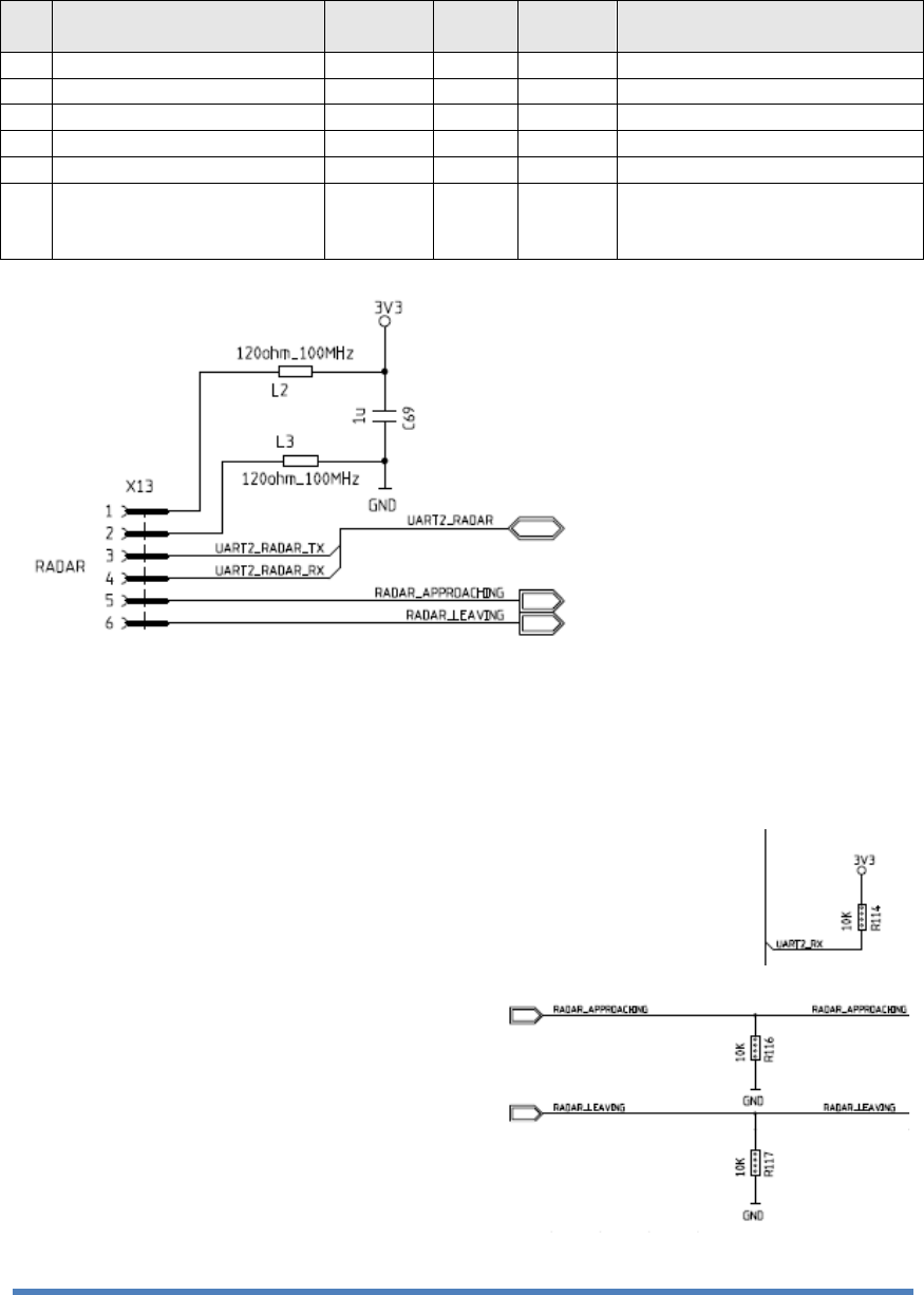
JRC radar interface
Connector:
flex cable connector (SFV6R-1STE9HLF)
Silkscreen:
RADAR
pin
signal
name
max.
voltage
Tol.
max.
current
description
1
3V3
power
2
GND
ground
3
UART_RADAR_TX
uart
4
UART_RADAR_RX
uart
5
RADAR_APPROACHING
object approaching signal
6
RADAR_LEAVING
object leaving signal
(optionally connected to
micro controller)
additional pull-up or pull-down resistors fro the following signals:
-
UART_RADAR_RX (resp. UART2_RX)
-
RADAR-APPROACHING
-
RADAR_LEAVING
11
© PORT Technology by Schindler Ltd - Oct 20, 2017
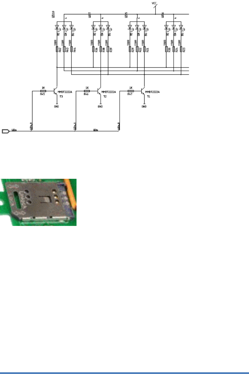
RGB LEDs
SAM sockets
optionally mounted:
prepared for HID SAM (socket 1), customized SAM (socket 2)
Connector:
see picture above
Silkscreen:
SAM1 resp. SAM2
12
© PORT Technology by Schindler Ltd - Oct 20, 2017
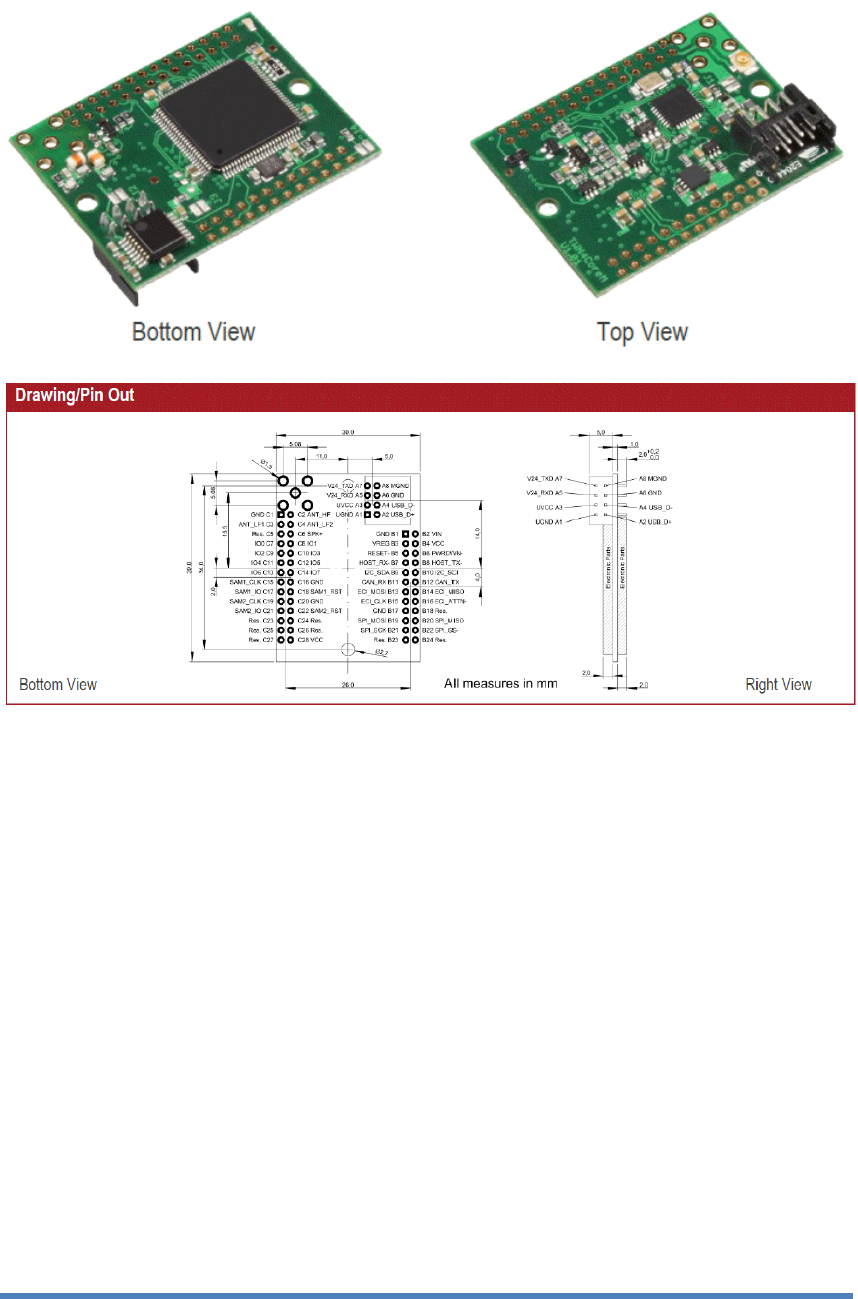
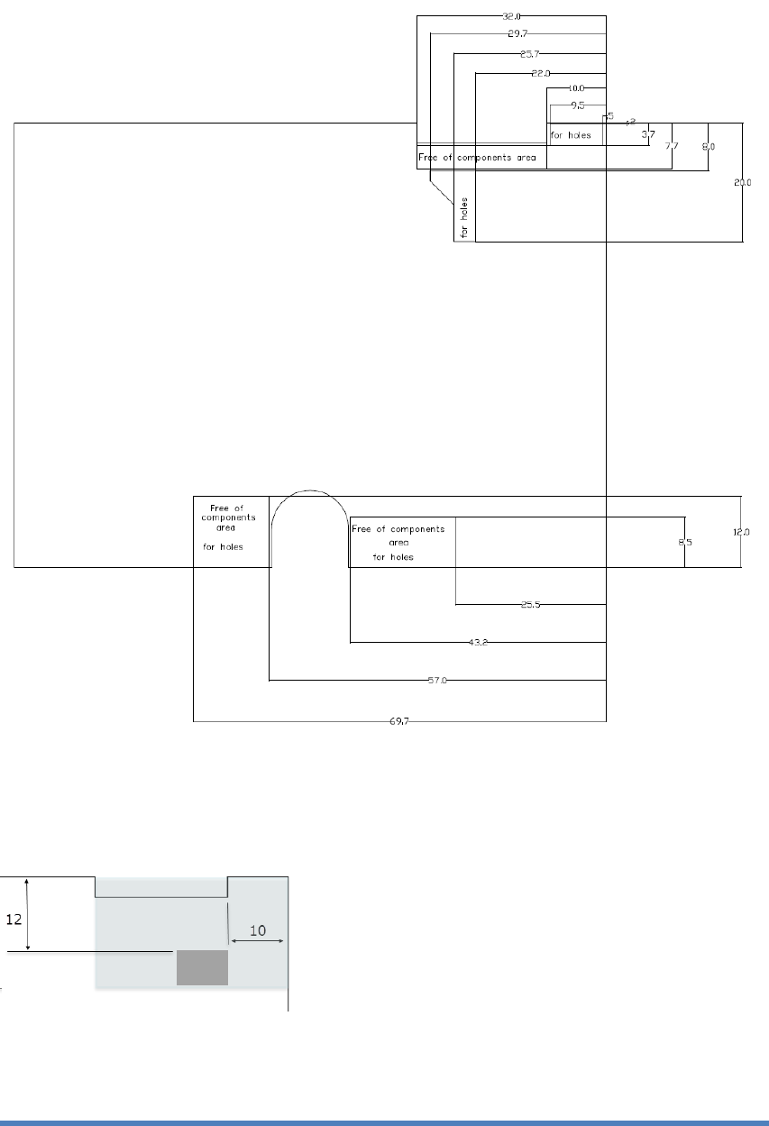
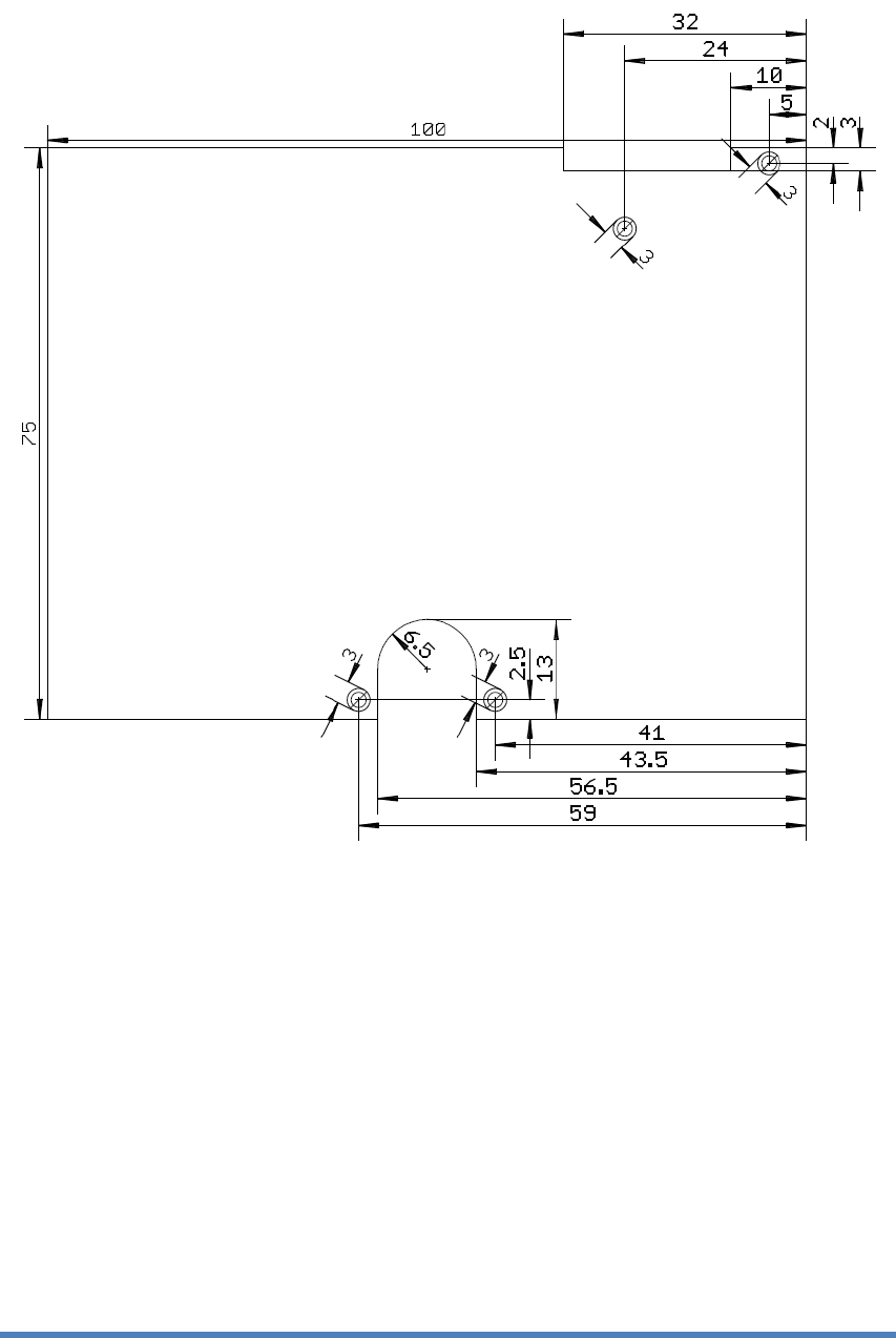
3 Mechanics
PCB size:
100 mm x 75 mm
PCB thickness:
1.6 mm
cutouts for
-
radar (top left corner)
-
camera (at button in the middle)
connector for K-LC1 radar positioned as designed in the top left corner (grey area)
connector for JRC radar in line with the cutout for the radar (green area)
position holes (d = 3mm) in the area where marked
13
© PORT Technology by Schindler Ltd - Oct 20, 2017
4 Reliability
EMC
The board must comply with the requirements of EN12015:2004 and EN12016:2004.
Tests are performed at system level.
Climatic conditions
Operating temperature:
ambient temperatures of 0 to 60 °C.
Relative humidity:
yearly average less or equal to 65%, 60 days 85%.
Altitude:
up to 2000 m above sea level.
Climatic tests are performed at system level.
Certifications
The PCR-TWN4 comply from 15.19 / 15.21 and RSS-Gen clause 8.4.
The PCR-TWN4 complies with the following requirements:
• FCC (Federal Communications Commission) Part 15
• IC (Industry Canada) RSS-102
This device complies with part 15 of the FCC Rules. Operation is subject to the following two conditions:
1. This device may not cause harmful interference
2. This device must accept any interference received, including interference that may cause
undesired operation
This device contains licence-exempt transmitter(s)/receiver(s) that comply with Innovation, Science and
Economic Development Canada’s licence-exempt RSS(s). Operation is subject to the following two
conditions:
• This device may not cause interference.
• This device must accept any interference, including interference that may cause undesired
operation of the device
Changes or modification not expressly approved by the party responsible for compliance could void the
user’s authority to operate the equipment.
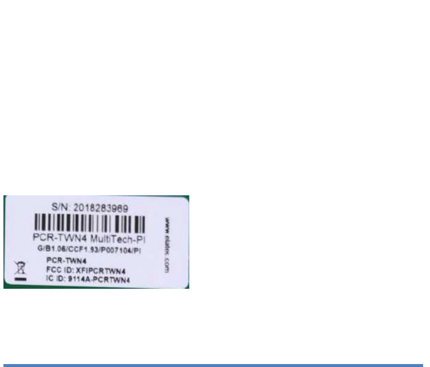
FCC ID: XFIPCRTWN4
IC ID: 9114A-PCRTWN4

14
© PORT Technology by Schindler Ltd - Oct 20, 2017
Label example of the final product
5 Document History
2015 Feb 9
Scs
Version 2
-
radar interface: electrical schematics adapted
-
input/output: max. current specified
2015 July 2
Scs
Version 3
-
additional cutouts on pcb for camera and radar
-
integration of JRC radar module
-
positioning of connector for K-LC1 radar module
2015 Aug 5
Scs
Version 4:
- mechanical dimensions updated
2017 Oct 20
Scs
Version 5:
- Input/Output schematic modified for external handicapped button
2018 Nov 17
Bua
Version 6:
chapter 2. General Board Implementation:
-
subchapter radio introduced
with description of modulation schemes
-
subchapter HF and LF antenna extended
with description of physical antenna dimension
chapter 4. Reliability
-
subchapter Certifications introduced
15
© PORT Technology by Schindler Ltd - Oct 20, 2017
6 Appendix
Sample layout of PCB according chapter 3: