Schlage Lock COPROX Proximity Reader User Manual P516 271 CO200 UG RevB 2 indd
Schlage Lock Company Proximity Reader P516 271 CO200 UG RevB 2 indd
UserManual.wiki
>
Schlage Lock
>
COPROX User Manual
User Manual
Navigation menu
Upload a User Manual
Namespaces
Wiki Guide
HTML
PDF
Info
Views
User Manual
Discussion / Help
Navigation
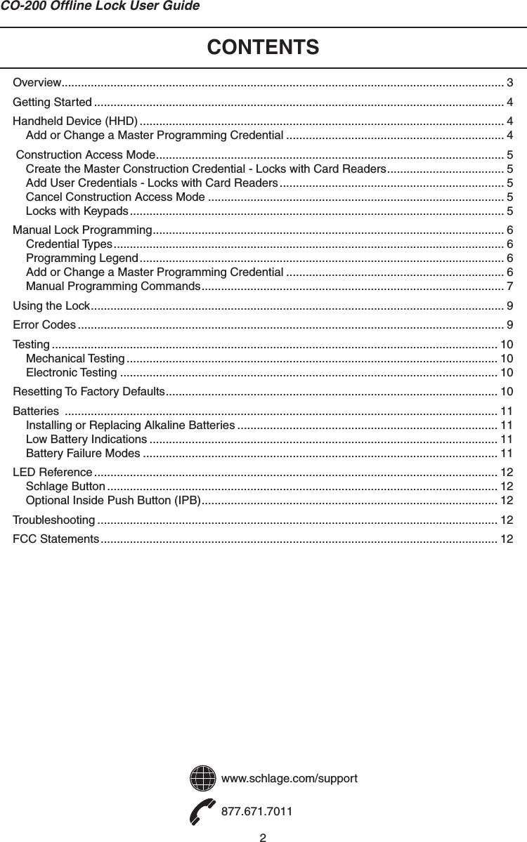
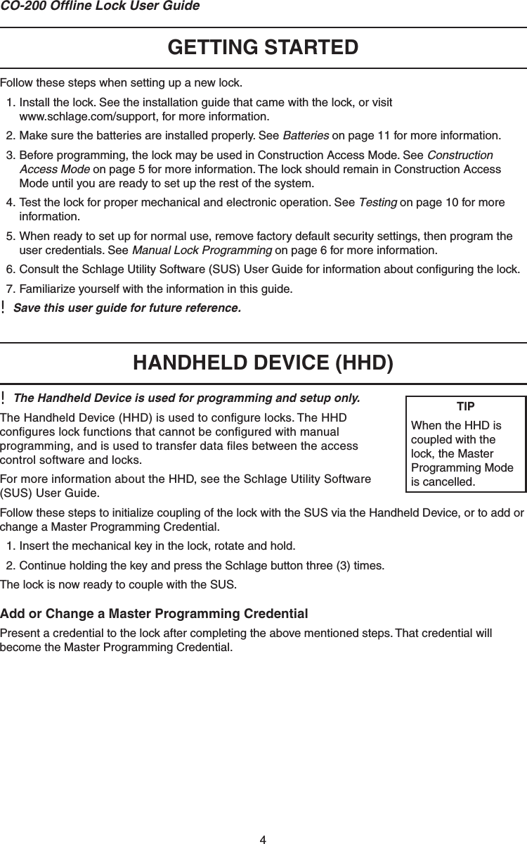
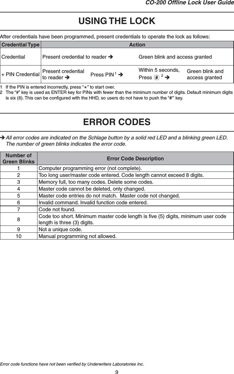
![6CO-200 Offl ine Lock User Guide MANUAL LOCK PROGRAMMINGLeft LED Right LED ! When adding a card credential, the 3-6 digit code (PIN) entered prior to presenting the card becomes the credential reference number. This number can be used to delete a card without physically having the card. Keep a log of all issued credential reference numbers and codes for future reference.Credential TypesCredential Type Function DescriptionProgramming Used to program the lock – does not unlock the lock Five-digit code OR cardNormal Use Unlocks the lock PIN (3 - 6 digits) OR cardNormal Use +PIN PIN (3 - 6 digits) AND cardToggle Changes the state of the lock from locked to unlocked, or vice versa, unless in a Freeze state PIN (3 - 6 digits) OR cardToggle +PIN PIN (3 - 6 digits) AND cardFreeze Freezes the lock in the current state – lock remains frozen until Freeze credential is presented againPIN (3 - 6 digits) OR cardFreeze +PIN PIN (3 - 6 digits) AND cardPass-Through Unlocks a lock momentarily, regardless of state Overrides a lock in Freeze statePIN (3 - 6 digits) OR cardPass-Through +PIN PIN (3 - 6 digits) AND cardProgramming LegendSymbol Description[Programming Code]1Five-digit code, identical to programming credential code listed in the Credential Types table.Programming Card Programming Card, identical to programming credential card listed in the Credential Types table.[PIN]Three- to Six-digit code. A PIN can be any of the PIN code types listed in the Credential Types table. A PIN entered before a card credential becomes the credential reference number.Asterisk key on the keypad - Number keys on the keypadSchlage button1 Programming codes such as 1-1-1 or 1-2-3-4 can be easily selected by non-authorizedusers and should not be used. Add or Change a Master Programming CredentialSee Handheld Device (HHD) on page 4 for more information.TIPSThe Schlage button has two different LEDs, one on the left and one on the right.All locks have a default programming code of 97531 and “*”.All locks have a default normal use code of 13579 and “#”.TIPUse the same programming code for all locks in the facility.](https://usermanual.wiki/Schlage-Lock/COPROX/User-Guide-1335650-Page-6.png)
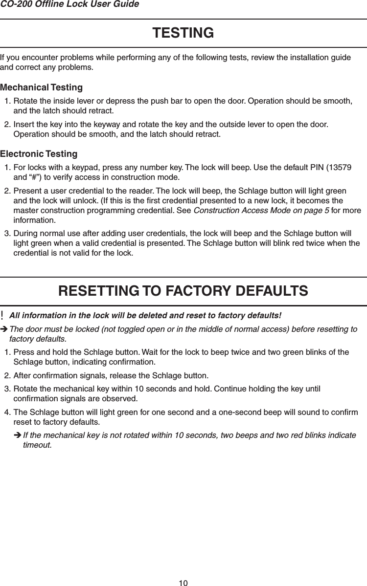
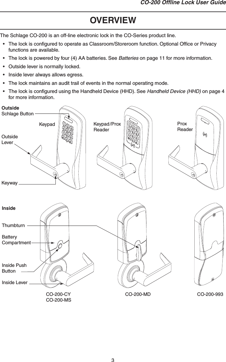
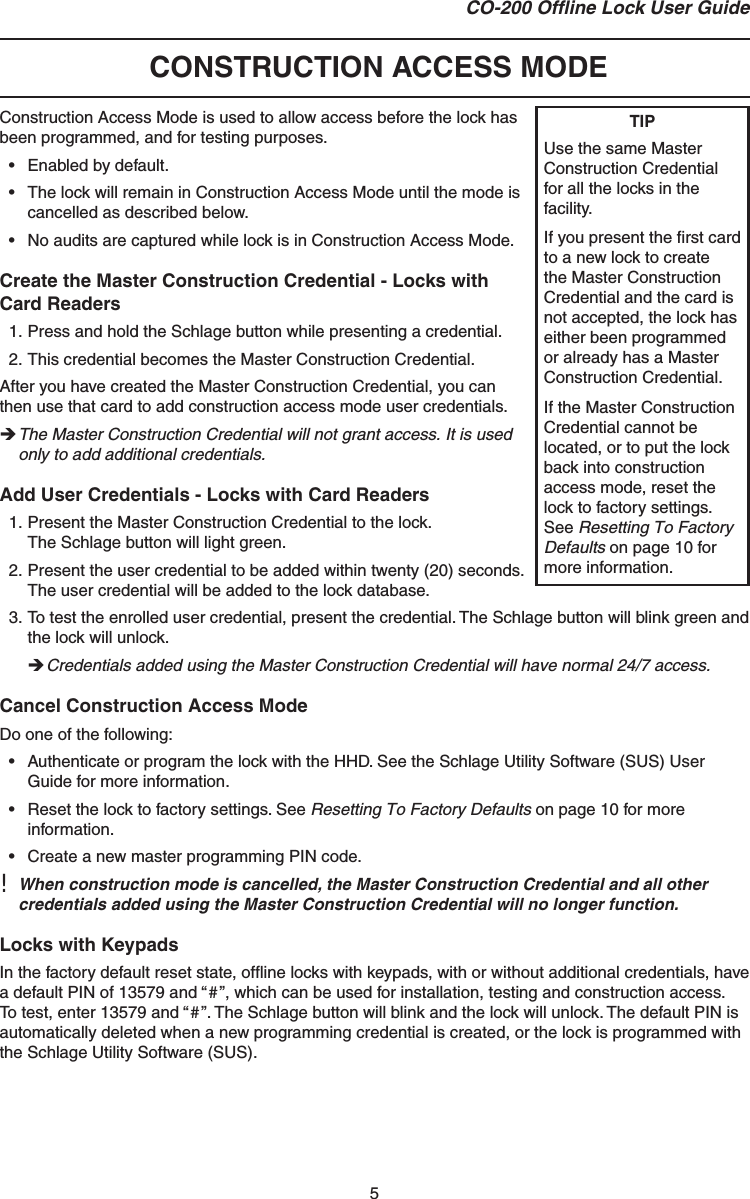
![7CO-200 Offl ine Lock User GuideManual Programming Commands Commands are confi rmed by fi ve alternating green blinks of the Schlage button. The right LED on the Schlage button will blink green to indicate an incorrect entry. To interpret blink patterns, refer to Error Codes on page 9.Function Press/PresentWait For Confi rmation1Change [Programming Code][Programming Code] OR Programming Card Wait for to stop flashing between each step. New [Programming Code] New [Programming Code] Change Programming Card[Programming Code] OR Programming Card Wait for to stop flashing between each step. New Programming CardAdd Normal Use Credential[Programming Code] OR Programming Card Wait for to stop flashing between each step. New [PIN] (for PIN only) OR New Cardadd another credential OR to finishAdd Normal Use +PIN Credential[Programming Code] OR Programming CardWait for to stop flashing between each step. New [PIN] New Cardadd another credential OR to finishAdd Toggle Credential[Programming Code] OR Programming CardWait for to stop flashing between each step. New [PIN] (for PIN only) OR New Cardadd another credential OR to finishAdd Toggle +PIN Credential[Programming Code] OR Programming CardWait for to stop flashing between each step. New [PIN] New Cardadd another credential OR to finishAdd Freeze Credential[Programming Code] OR Programming CardWait for to stop flashing between each step. New [PIN] (for PIN only) OR New Cardadd another credential OR to finish1 Other lights may show before the fi nal confi rmation. Wait for fi nal confi rmation before continuing to the next step.](https://usermanual.wiki/Schlage-Lock/COPROX/User-Guide-1335650-Page-7.png)
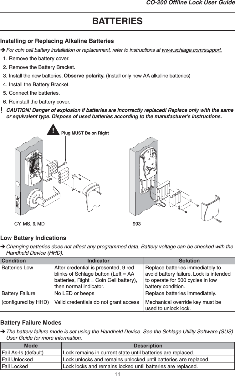
![8CO-200 Offl ine Lock User GuideFunction Press/PresentWait For Confi rmation1Add Freeze +PIN Credential[Programming Code] OR Programming CardWait for to stop flashing between each step. New [PIN] New Cardadd another credential OR to finishAdd Pass Through Credential[Programming Code] OR Programming CardWait for to stop flashing between each step. New [PIN] (for PIN only) OR New Cardadd another credential OR to finishAdd Pass Through +PIN Credential[Programming Code] OR Programming CardWait for to stop flashing between each step. New [PIN] New Cardadd another credential OR to finishDelete Credential[Programming Code] OR Programming Card Wait for to stop flashing between each step. Credential [PIN] delete another credential OR to finishChange Relock Time[Programming Code] OR Programming Card Wait for to stop flashing between each step. to add 1 second AND/OR to add 5 seconds to finishDisable/Enable Beeper[Programming Code] Wait for to stop flashing between each step. to disable beeper OR to enable beeper1 Other lights may show before the fi nal confi rmation. Wait for fi nal confi rmation before continuing to the next step.](https://usermanual.wiki/Schlage-Lock/COPROX/User-Guide-1335650-Page-8.png)