Schlage Lock COPROX Proximity Reader User Manual P516 271 CO200 UG RevB 2 indd
Schlage Lock Company Proximity Reader P516 271 CO200 UG RevB 2 indd
User Manual
CO-200
OFFLINE LOCK USER GUIDE
INSTRUCTIONS FOR CORE SERIES OFFLINE LOCKS
Para el idioma español, navegue hacia www.schlage.com/support.
Pour la portion française, veuillez consulter le site www.schlage.com/support.
P516-271

2
CO-200 Offl ine Lock User Guide
CONTENTS
Overview ........................................................................................................................................ 3
Getting Started .............................................................................................................................. 4
Handheld Device (HHD) ................................................................................................................ 4
Add or Change a Master Programming Credential ................................................................... 4
Construction Access Mode ........................................................................................................... 5
Create the Master Construction Credential - Locks with Card Readers .................................... 5
Add User Credentials - Locks with Card Readers ..................................................................... 5
Cancel Construction Access Mode ........................................................................................... 5
Locks with Keypads ................................................................................................................... 5
Manual Lock Programming ............................................................................................................ 6
Credential Types ........................................................................................................................ 6
Programming Legend ................................................................................................................ 6
Add or Change a Master Programming Credential ................................................................... 6
Manual Programming Commands ............................................................................................. 7
Using the Lock ............................................................................................................................... 9
Error Codes ................................................................................................................................... 9
Testing ......................................................................................................................................... 10
Mechanical Testing .................................................................................................................. 10
Electronic Testing .................................................................................................................... 10
Resetting To Factory Defaults ...................................................................................................... 10
Batteries ..................................................................................................................................... 11
Installing or Replacing Alkaline Batteries ................................................................................ 11
Low Battery Indications ........................................................................................................... 11
Battery Failure Modes ............................................................................................................. 11
LED Reference ............................................................................................................................ 12
Schlage Button ........................................................................................................................ 12
Optional Inside Push Button (IPB) ........................................................................................... 12
Troubleshooting ........................................................................................................................... 12
FCC Statements .......................................................................................................................... 12
www.schlage.com/support
877.671.7011
3
CO-200 Offl ine Lock User Guide
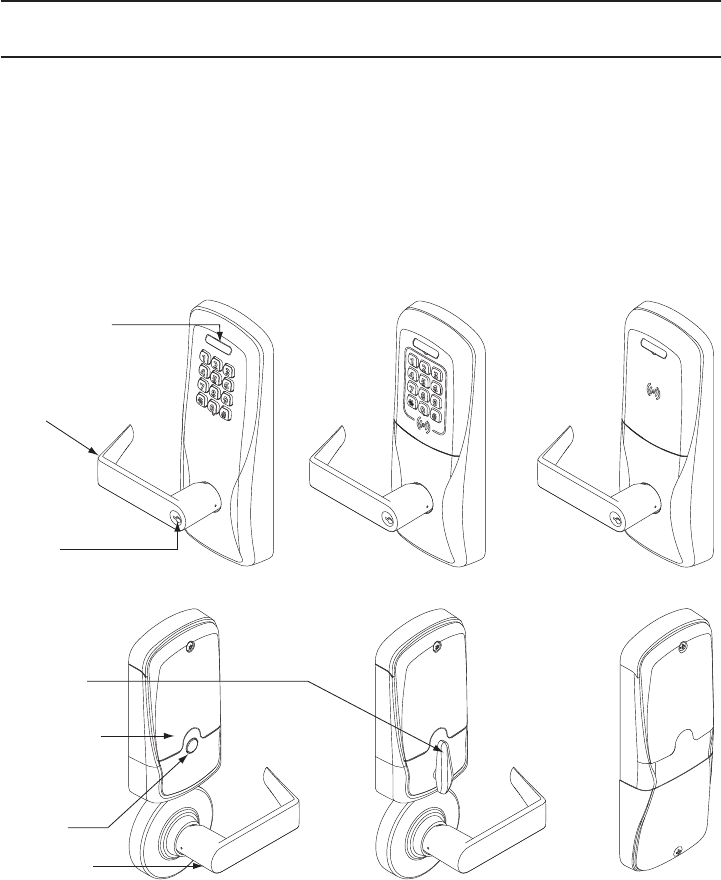
OVERVIEW
The Schlage CO-200 is an off-line electronic lock in the CO-Series product line.
• The lock is confi gured to operate as Classroom/Storeroom function. Optional Offi ce or Privacy
functions are available.
• The lock is powered by four (4) AA batteries. See Batteries on page 11 for more information.
• Outside lever is normally locked.
• Inside lever always allows egress.
• The lock maintains an audit trail of events in the normal operating mode.
• The lock is confi gured using the Handheld Device (HHD). See Handheld Device (HHD) on page 4
for more information.
Outside
Schlage Button
Outside
Lever
Keyway
Inside
Thumbturn
Battery
Compartment
Inside Push
Button
Inside Lever
Keypad Keypad/Prox
Reader
Prox
Reader
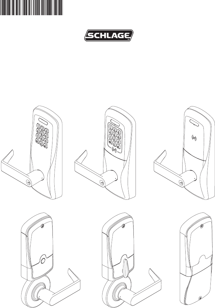
CO-200-CY
CO-200-MS
CO-200-MD CO-200-993
4
CO-200 Offl ine Lock User Guide
GETTING STARTED
Follow these steps when setting up a new lock.
1. Install the lock. See the installation guide that came with the lock, or visit
www.schlage.com/support, for more information.
2. Make sure the batteries are installed properly. See Batteries on page 11 for more information.
3. Before programming, the lock may be used in Construction Access Mode. See Construction
Access Mode on page 5 for more information. The lock should remain in Construction Access
Mode until you are ready to set up the rest of the system.
4. Test the lock for proper mechanical and electronic operation. See Testing on page 10 for more
information.
5. When ready to set up for normal use, remove factory default security settings, then program the
user credentials. See Manual Lock Programming on page 6 for more information.
6. Consult the Schlage Utility Software (SUS) User Guide for information about confi guring the lock.
7. Familiarize yourself with the information in this guide.
! Save this user guide for future reference.
HANDHELD DEVICE (HHD)
! The Handheld Device is used for programming and setup only.
The Handheld Device (HHD) is used to confi gure locks. The HHD
confi gures lock functions that cannot be confi gured with manual
programming, and is used to transfer data fi les between the access
control software and locks.
For more information about the HHD, see the Schlage Utility Software
(SUS) User Guide.
Follow these steps to initialize coupling of the lock with the SUS via the Handheld Device, or to add or
change a Master Programming Credential.
1. Insert the mechanical key in the lock, rotate and hold.
2. Continue holding the key and press the Schlage button three (3) times.
The lock is now ready to couple with the SUS.
Add or Change a Master Programming Credential
Present a credential to the lock after completing the above mentioned steps. That credential will
become the Master Programming Credential.
TIP
When the HHD is
coupled with the
lock, the Master
Programming Mode
is cancelled.

5
CO-200 Offl ine Lock User Guide
CONSTRUCTION ACCESS MODE
Construction Access Mode is used to allow access before the lock has
been programmed, and for testing purposes.
• Enabled by default.
• The lock will remain in Construction Access Mode until the mode is
cancelled as described below.
• No audits are captured while lock is in Construction Access Mode.
Create the Master Construction Credential - Locks with
Card Readers
1. Press and hold the Schlage button while presenting a credential.
2. This credential becomes the Master Construction Credential.
After you have created the Master Construction Credential, you can
then use that card to add construction access mode user credentials.
The Master Construction Credential will not grant access. It is used
only to add additional credentials.
Add User Credentials - Locks with Card Readers
1. Present the Master Construction Credential to the lock.
The Schlage button will light green.
2. Present the user credential to be added within twenty (20) seconds.
The user credential will be added to the lock database.
3. To test the enrolled user credential, present the credential. The Schlage button will blink green and
the lock will unlock.
Credentials added using the Master Construction Credential will have normal 24/7 access.
Cancel Construction Access Mode
Do one of the following:
• Authenticate or program the lock with the HHD. See the Schlage Utility Software (SUS) User
Guide for more information.
• Reset the lock to factory settings. See Resetting To Factory Defaults on page 10 for more
information.
• Create a new master programming PIN code.
! When construction mode is cancelled, the Master Construction Credential and all other
credentials added using the Master Construction Credential will no longer function.
Locks with Keypads
In the factory default reset state, offl ine locks with keypads, with or without additional credentials, have
a default PIN of 13579 and “#”, which can be used for installation, testing and construction access.
To test, enter 13579 and “#”. The Schlage button will blink and the lock will unlock. The default PIN is
automatically deleted when a new programming credential is created, or the lock is programmed with
the Schlage Utility Software (SUS).
TIP
Use the same Master
Construction Credential
for all the locks in the
facility.
If you present the fi rst card
to a new lock to create
the Master Construction
Credential and the card is
not accepted, the lock has
either been programmed
or already has a Master
Construction Credential.
If the Master Construction
Credential cannot be
located, or to put the lock
back into construction
access mode, reset the
lock to factory settings.
See Resetting To Factory
Defaults on page 10 for
more information.
6
CO-200 Offl ine Lock User Guide
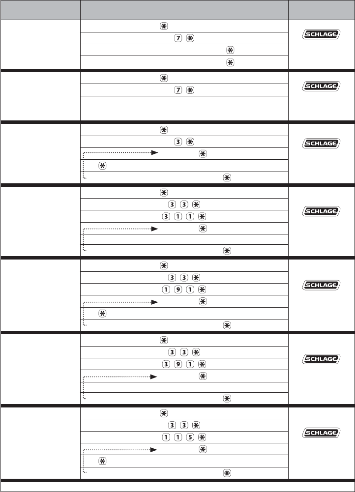
MANUAL LOCK PROGRAMMING
Left LED Right LED
! When adding a card credential, the 3-6 digit code (PIN) entered prior to presenting the card
becomes the credential reference number. This number can be used to delete a card without
physically having the card. Keep a log of all issued credential reference numbers and codes
for future reference.
Credential Types
Credential Type Function Description
Programming Used to program the lock – does not unlock the lock Five-digit code OR card
Normal Use Unlocks the lock PIN (3 - 6 digits) OR card
Normal Use +PIN PIN (3 - 6 digits) AND card
Toggle Changes the state of the lock from locked to
unlocked, or vice versa, unless in a Freeze state
PIN (3 - 6 digits) OR card
Toggle +PIN PIN (3 - 6 digits) AND card
Freeze Freezes the lock in the current state – lock remains
frozen until Freeze credential is presented again
PIN (3 - 6 digits) OR card
Freeze +PIN PIN (3 - 6 digits) AND card
Pass-Through Unlocks a lock momentarily, regardless of state
Overrides a lock in Freeze state
PIN (3 - 6 digits) OR card
Pass-Through +PIN PIN (3 - 6 digits) AND card
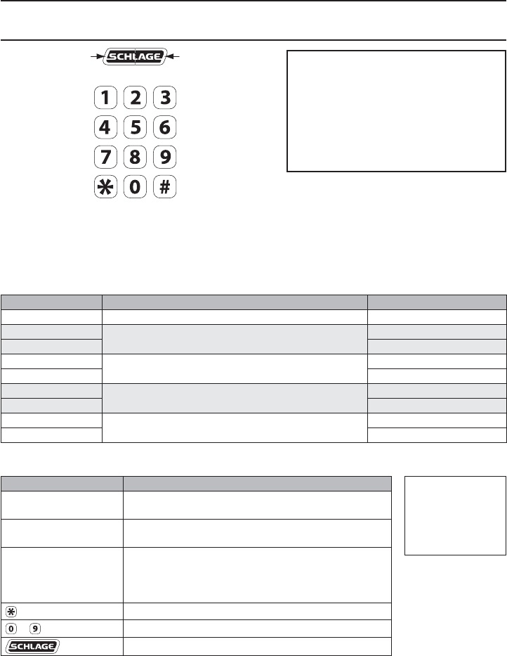
Programming Legend
Symbol Description
[Programming Code]1Five-digit code, identical to programming credential
code listed in the Credential Types table.
Programming Card Programming Card, identical to programming
credential card listed in the Credential Types table.
[PIN]
Three- to Six-digit code. A PIN can be any of the
PIN code types listed in the Credential Types table.
A PIN entered before a card credential becomes the
credential reference number.
Asterisk key on the keypad
- Number keys on the keypad
Schlage button
1 Programming codes such as 1-1-1 or 1-2-3-4 can be easily selected by non-authorized
users and should not be used.
Add or Change a Master Programming Credential
See Handheld Device (HHD) on page 4 for more information.
TIPS
The Schlage button has two different
LEDs, one on the left and one on the right.
All locks have a default programming
code of 97531 and “*”.
All locks have a default normal use
code of 13579 and “#”.
TIP
Use the same
programming code
for all locks in the
facility.
7
CO-200 Offl ine Lock User Guide
Manual Programming Commands
Commands are confi rmed by fi ve alternating green blinks of the Schlage button.
The right LED on the Schlage button will blink green to indicate an incorrect entry. To interpret blink
patterns, refer to Error Codes on page 9.
Function Press/Present
Wait For
Confi rmation1
Change
[Programming Code]
[Programming Code] OR Programming Card Wait for
to stop flashing
between each
step.
New [Programming Code]
New [Programming Code]
Change
Programming Card
[Programming Code] OR Programming Card Wait for
to stop flashing
between each
step.
New Programming Card
Add Normal Use
Credential
[Programming Code] OR Programming Card Wait for
to stop flashing
between each
step.
New [PIN]
(for PIN only) OR New Card
add another credential OR to finish
Add Normal Use
+PIN Credential
[Programming Code] OR Programming Card
Wait for
to stop flashing
between each
step.
New [PIN]
New Card
add another credential OR to finish
Add Toggle
Credential
[Programming Code] OR Programming Card
Wait for
to stop flashing
between each
step.
New [PIN]
(for PIN only) OR New Card
add another credential OR to finish
Add Toggle +PIN
Credential
[Programming Code] OR Programming Card
Wait for
to stop flashing
between each
step.
New [PIN]
New Card
add another credential OR to finish
Add Freeze
Credential
[Programming Code] OR Programming Card
Wait for
to stop flashing
between each
step.
New [PIN]
(for PIN only) OR New Card
add another credential OR to finish
1 Other lights may show before the fi nal confi rmation. Wait for fi nal confi rmation before continuing to the next step.
8
CO-200 Offl ine Lock User Guide
Function Press/Present
Wait For
Confi rmation1
Add Freeze +PIN
Credential
[Programming Code] OR Programming Card
Wait for
to stop flashing
between each
step.
New [PIN]
New Card
add another credential OR to finish
Add Pass Through
Credential
[Programming Code] OR Programming Card
Wait for
to stop flashing
between each
step.
New [PIN]
(for PIN only) OR New Card
add another credential OR to finish
Add Pass Through
+PIN Credential
[Programming Code] OR Programming Card
Wait for
to stop flashing
between each
step.
New [PIN]
New Card
add another credential OR to finish
Delete Credential
[Programming Code] OR Programming Card Wait for
to stop flashing
between each
step.
Credential [PIN]
delete another credential OR to finish
Change Relock Time
[Programming Code] OR Programming Card Wait for
to stop flashing
between each
step.
to add 1 second AND/OR to add 5 seconds
to finish
Disable/Enable
Beeper
[Programming Code] Wait for
to stop flashing
between each
step.
to disable beeper OR to enable beeper
1 Other lights may show before the fi nal confi rmation. Wait for fi nal confi rmation before continuing to the next step.
9
CO-200 Offl ine Lock User Guide
USING THE LOCK
After credentials have been programmed, present credentials to operate the lock as follows:
Credential Type Action
Credential Present credential to reader Green blink and access granted
+ PIN Credential Present credential
to reader Press PIN 1 Within 5 seconds,
Press 2
Green blink and
access granted
1 If the PIN is entered incorrectly, press “*” to start over.
2 The “#” key is used as ENTER key for PINs with fewer than the minimum number of digits. Default minimum digits
is six (6). This can be confi gured with the HHD, so users do not have to push the “#” key.
ERROR CODES
All error codes are indicated on the Schlage button by a solid red LED and a blinking green LED.
The number of green blinks indicates the error code.
Number of
Green Blinks Error Code Description
1 Computer programming error (not complete).
2 Too long user/master code entered. Code length cannot exceed 8 digits.
3 Memory full, too many codes. Delete some codes.
4 Master code cannot be deleted, only changed.
5 Master code entries do not match. Master code not changed.
6 Invalid command. Invalid function code entered.
7 Code not found.
8Code too short. Minimum master code length is fi ve (5) digits, minimum user code
length is three (3) digits.
9 Not a unique code.
10 Manual programming not allowed.
Error code functions have not been verifi ed by Underwriters Laboratories Inc.

10
CO-200 Offl ine Lock User Guide
TESTING
If you encounter problems while performing any of the following tests, review the installation guide
and correct any problems.
Mechanical Testing
1. Rotate the inside lever or depress the push bar to open the door. Operation should be smooth,
and the latch should retract.
2. Insert the key into the keyway and rotate the key and the outside lever to open the door.
Operation should be smooth, and the latch should retract.
Electronic Testing
1. For locks with a keypad, press any number key. The lock will beep. Use the default PIN (13579
and “#”) to verify access in construction mode.
2. Present a user credential to the reader. The lock will beep, the Schlage button will light green
and the lock will unlock. (If this is the fi rst credential presented to a new lock, it becomes the
master construction programming credential. See Construction Access Mode on page 5 for more
information.
3. During normal use after adding user credentials, the lock will beep and the Schlage button will
light green when a valid credential is presented. The Schlage button will blink red twice when the
credential is not valid for the lock.
RESETTING TO FACTORY DEFAULTS
! All information in the lock will be deleted and reset to factory defaults!
The door must be locked (not toggled open or in the middle of normal access) before resetting to
factory defaults.
1. Press and hold the Schlage button. Wait for the lock to beep twice and two green blinks of the
Schlage button, indicating confi rmation.
2. After confi rmation signals, release the Schlage button.
3. Rotate the mechanical key within 10 seconds and hold. Continue holding the key until
confi rmation signals are observed.
4. The Schlage button will light green for one second and a one-second beep will sound to confi rm
reset to factory defaults.
If the mechanical key is not rotated within 10 seconds, two beeps and two red blinks indicate
timeout.
11
CO-200 Offl ine Lock User Guide
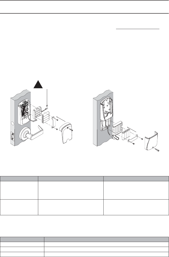
BATTERIES
Installing or Replacing Alkaline Batteries
For coin cell battery installation or replacement, refer to instructions at www.schlage.com/support.
1. Remove the battery cover.
2. Remove the Battery Bracket.
3. Install the new batteries. Observe polarity. (Install only new AA alkaline batteries)
4. Install the Battery Bracket.
5. Connect the batteries.
6. Reinstall the battery cover.
! CAUTION! Danger of explosion if batteries are incorrectly replaced! Replace only with the same
or equivalent type. Dispose of used batteries according to the manufacturer’s instructions.
CY, MS, & MD 993
!Plug MUST Be on Right
Low Battery Indications
Changing batteries does not affect any programmed data. Battery voltage can be checked with the
Handheld Device (HHD).
Condition Indicator Solution
Batteries Low After credential is presented, 9 red
blinks of Schlage button (Left = AA
batteries, Right = Coin Cell battery),
then normal indicator.
Replace batteries immediately to
avoid battery failure. Lock is intended
to operate for 500 cycles in low
battery condition.
Battery Failure
(confi gured by HHD)
No LED or beeps
Valid credentials do not grant access
Replace batteries immediately.
Mechanical override key must be
used to unlock lock.
Battery Failure Modes
The battery failure mode is set using the Handheld Device. See the Schlage Utility Software (SUS)
User Guide for more information.
Mode Description
Fail As-Is (default) Lock remains in current state until batteries are replaced.
Fail Unlocked Lock unlocks and remains unlocked until batteries are replaced.
Fail Locked Lock locks and remains locked until batteries are replaced.
© 2010 Ingersoll-Rand Company
Printed in Country
P516-271 Rev. 08/10-b
LED REFERENCE
Most LED indicators are confi gured with the HHD. See Schlage Utility Software (SUS) User Guide for
more information.
Schlage Button
Condition Lights
Access denied 2 red blinks
Access denied, user outside time zone 4 red blinks
Factory default reset One-second solid green with one-second beep
Waiting for PIN Mode 0 only: 5 left red with right green blinks,
then solid right green
Low battery indicator, AA batteries 9 left red blinks
Low battery indicator, coin cell battery 9 right red blinks
Momentary unsecured access 1 green blink, then one red blink on relock
USB active with no physical connection Left green blinking
Optional Inside Push Button (IPB)
Action Lights
Offi ce Mode –Allows lock to toggle between locked (normal) and unlocked state
Press IPB to lock 1 red blink
Press IPB to unlock11 green blink
Privacy Mode – Allows the lock to toggle between normal access and a state in which normal
credentials are ignored
With door closed, press IPB to engage privacy24 green blinks
With door closed, press IPB to release privacy34 red blinks
1 Unlocking the lock with the IPB will cause the lock to remain unlocked until the IPB is depressed again.
2 On locks confi gured with a mortise-deadbolt, throwing the deadbolt will also engage privacy.
3 If DPS is used, then opening door will also release privacy. If a mortise-deadbolt is used, then retracting the
deadbolt will also release privacy.
TROUBLESHOOTING
For troubleshooting, visit to www.schlage.com/support.
FCC STATEMENTS
This device complies with Part 15 of the FCC Rules.
Operation is subject to the following two conditions:
1. this device may not cause harmful interference, and
2. this device must accept any interference received,
including interference that may cause undesired operation.

Ingersoll Rand Security Technology
User Manual Statements
Compliance Statement (Part 15.19)
This device complies with Part 15 of the FCC Rules.
Operation is subject to the following two conditions:
1. This device may not cause harmful interference, and
2. This device must accept any interference received,
including interference that may cause undesired operation.
Warning (Part 15.21)
Changes or modifications not expressly approved by the party
responsible for compliance could void the user’s authority to
operate the equipment.
FCC Interference Statement (Part 15.105 (b))
This equipment has been tested and found to comply with the limits for a Class B digital
device, pursuant to Part 15 of the FCC Rules. These limits are designed to provide
reasonable protection against harmful interference in a residential installation. This
equipment generates uses and can radiate radio frequency energy and, if not installed
and used in accordance with the instructions, may cause harmful interference to radio
communications. However, there is no guarantee that interference will not occur in a
particular installation. If this equipment does cause harmful interference to radio or
television reception, which can be determined by turning the equipment off and on, the
user is encouraged to try to correct the interference by one of the following measures:
- Reorient or relocate the receiving antenna.
- Increase the separation between the equipment and receiver.
- Connect the equipment into an outlet on a circuit different from that
to which the receiver is connected.
- Consult the dealer or an experienced radio/TV technician for help.
RF Exposure Statement
To comply with FCC/IC RF exposure requirements for mobile transmitting
devices, this transmitter should only be used or installed at locations where there
is at least 20cm separation distance between the antenna and all persons.
Section 7.1.5 of RSS-GEN
Operation is subject to the following two conditions:
1) this device may not cause interference, and
2) this device must accept any interference,
including interference that may cause undesired operation of the device.