Schlage A Series Service Manual 106720
User Manual: Schlage Schlage A Series Service Manual Service Manual
Open the PDF directly: View PDF ![]() .
.
Page Count: 32
- Introduction
- Lock Assembly Drawing Index
- Chassis and Assemblies
- Parts and Accessories
- Passage Lock
- Exit Lock
- Patio Lock
- Bath/Bedroom Privacy Lock
- Communicating Lock
- Entrance Lock
- Classroom Lock
- Communicating Lock
- Storeroom Lock
- Faculty/Restroom Lock
- Dummy Trim
- Knob and Lever Designs
- Latches
- Strikes
- Finishes
- Cylinder Units and Parts
- Interchangeable Cores, Designs, and Parts
- Lubrication
- Installation Tools and Kits
- Long Backsets
- Reinforcement Kit
- Keying
A-Series
Service manual

Contents
5 Introduction
5 Lock Assembly Drawing Index
7 Chassis and Assemblies
8 Passage Lock
9 Exit Lock
10 Patio Lock
11 Bath/Bedroom Privacy Lock
12 Communicating Lock
13 Entrance Lock
14 Classroom Lock
15 Communicating Lock
16 Storeroom Lock
17 Faculty/Restroom Lock
18 Dummy Trim
19 Parts and Accessories
20 Knob and Lever Designs
21 Latches
22 Strikes
23 Finishes
24 Cylinder Units and Parts
26 Interchangeable Cores, Designs, and Parts
28 Lubrication
28 Installation Tools and Kits
29 Long Backsets
29 Reinforcement Kit
30 Keying
Introduction
Schlage • A-Series service manual • 5
Introduction
This manual contains a complete listing of A-Series (Grade 2) cylindrical lock parts and assemblies manufactured by the
Schlage Lock Company. This manual lists components of A-Series locks manufactured aer 1984.
Exploded views of each lock chassis and trim assemblies are provided with an accompanying chart to identify parts for
replacement purposes. In addition, this manual provides lock trim ordering procedures, general cylinder information, and all
auxiliary components of the A-Series cylindrical locks.
Standard Features*
Certifications ANSI A156.2, 2003, Series 4000, Grade 2, UL Listed for 3-hour fire door.
Latchbolt Z\x” throw, brass, chrome plated, deadlocking on keyed and exterior functions.
Strike T-Strike 1Z\,” x 2C\v”, Square corner, box.
Backset 2C\,” standard
Cylinder 6-Pin solid brass, keyed 6-pin, C123 keyway, keyed different (KD)**
Door Range 1C\,” - 1M\,”
Keys Two nickel silver cut keys per lock, 6-pin, C123 section**
* Locks are furnished with standard features unless otherwise specified.
** Items specified in C keyway will be furnished with cylinder keyed 5-pin and with 5-pin keys unless otherwise specified.
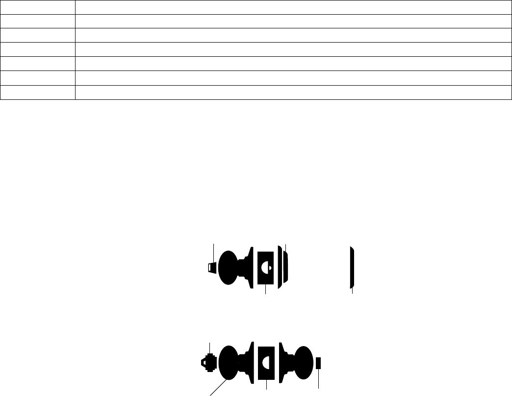
Lock Assembly Drawing Index
The Lock Assembly Drawing Index provides visual representations and textual descriptions of available functions. Page
numbers for full trim and chassis drawings are referenced.
Fixed Knob
or Active Knob
Blank
Plate
Key
Push-button
Turn/Push-button
Deadlatch
Springlatch
Thumbturn
Outside Inside
6 • Schlage • A-Series service manual
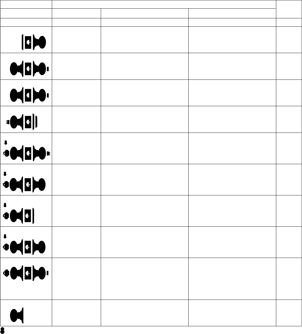
Lock Assembly Drawing Index
Function ANSI/BHMA A156.2, 2003, Series 4000, Grade 2 Chassis
and Trim
Page
SCHLAGE ANSI DESCRIPTION OUTSIDE FUNCTION INSIDE FUNCTION
A10S F75 Passage Latch Both knobs always unlocked. 8
A25D Exit Lock Blank plate outside. Inside knob always unlocked. Specify
door thickness, 1C\," or 1C\v".
9
A30D F77 Patio Lock Push-button locking. Turning inside knob
or closing door releases button,
preventing lock-out.
10
A40S F76 Bath/Bedroom
Privacy Lock
Can be opened from outside with small
screwdriver when locked with inside
push-button.
Push-button locking. Turning inside knob
or closing door releases button.
11
A43D F79 Communicating Lock Turn-button in outside knob locks and
unlocks outside knob and inside
thumbturn.
Inside thumbturn locked and unlocked by
outside turn-button.
12
A53PD F109 Entrance Lock Can be opened from outside with small
screwdriver or emergency release tool.
Push-button locks outside lever. Turning
inside lever or closing door releases
button. Inside lever is always free for
immediate egress.
13
A70PD F84 Classroom Lock Outside knob locked and unlocked by
key.
Inside knob is always unlocked. 14
A79PD Communicating Lock Locked or unlocked by key from outside. Inside knob is always unlocked. 15
A80PD F86 Storeroom Lock Outside knob is fixed.
Entrance by key only.
Inside knob is always unlocked. 16
A85PD F93 Faculty/Restroom
Lock (with Indicator
Cylinder)
Outside knob is fixed. Entrance by key
only.
Push-button in inside knob activates
visual occupancy indicator, allowing only
emergency master key to operate.
Turning inside knob or closing door
releases visual occupancy indicator.
Rotation of inside spanner-button
provides lock-out feature by keeping
indicator thrown.
17
A170 Single Dummy Dummy trim for one side of the door.
Used fo door pull or as matching inactive
trim.
18
Keyed functions available with full size interchangeable core option for Orbit design.

8 • Schlage • A-Series service manual
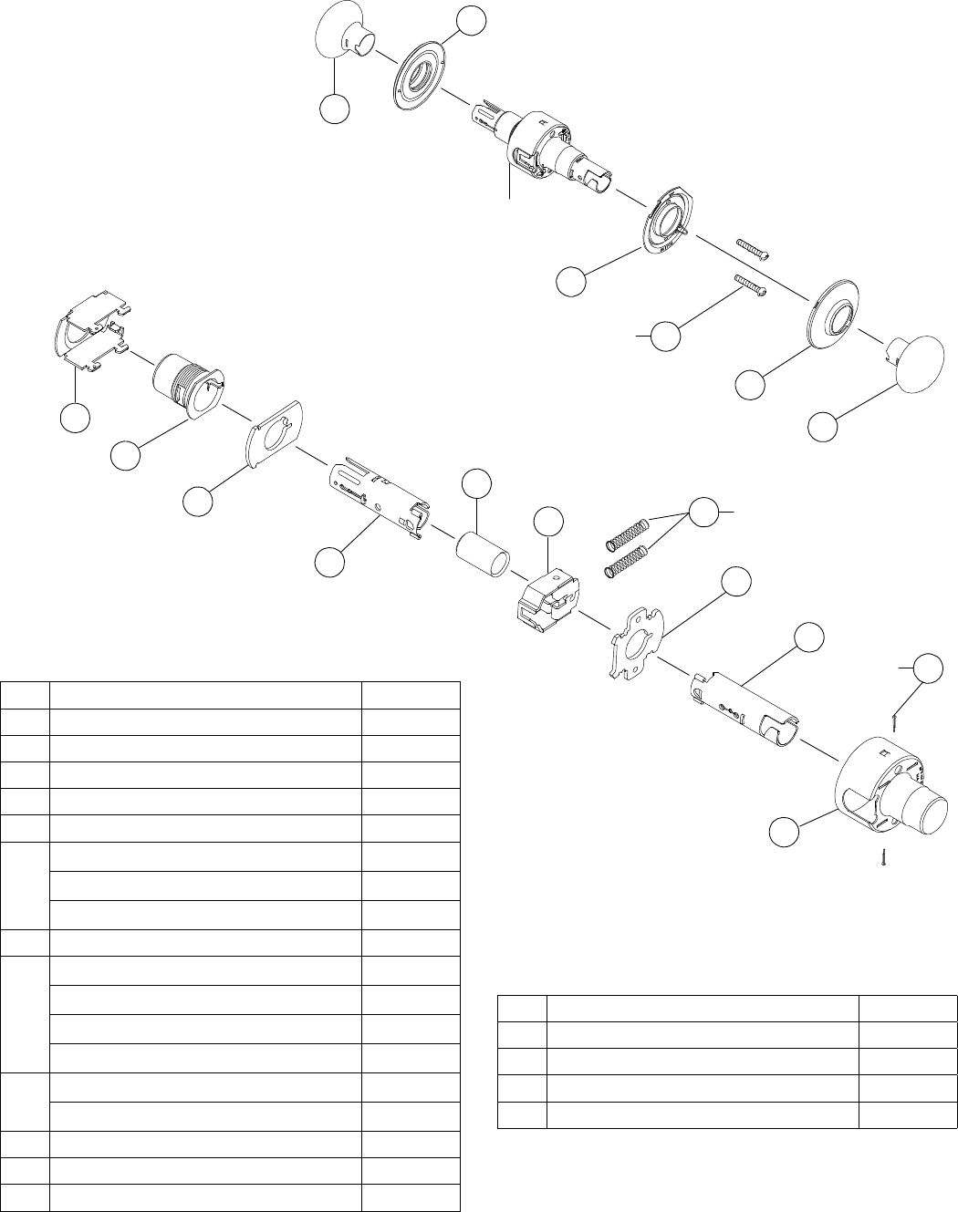
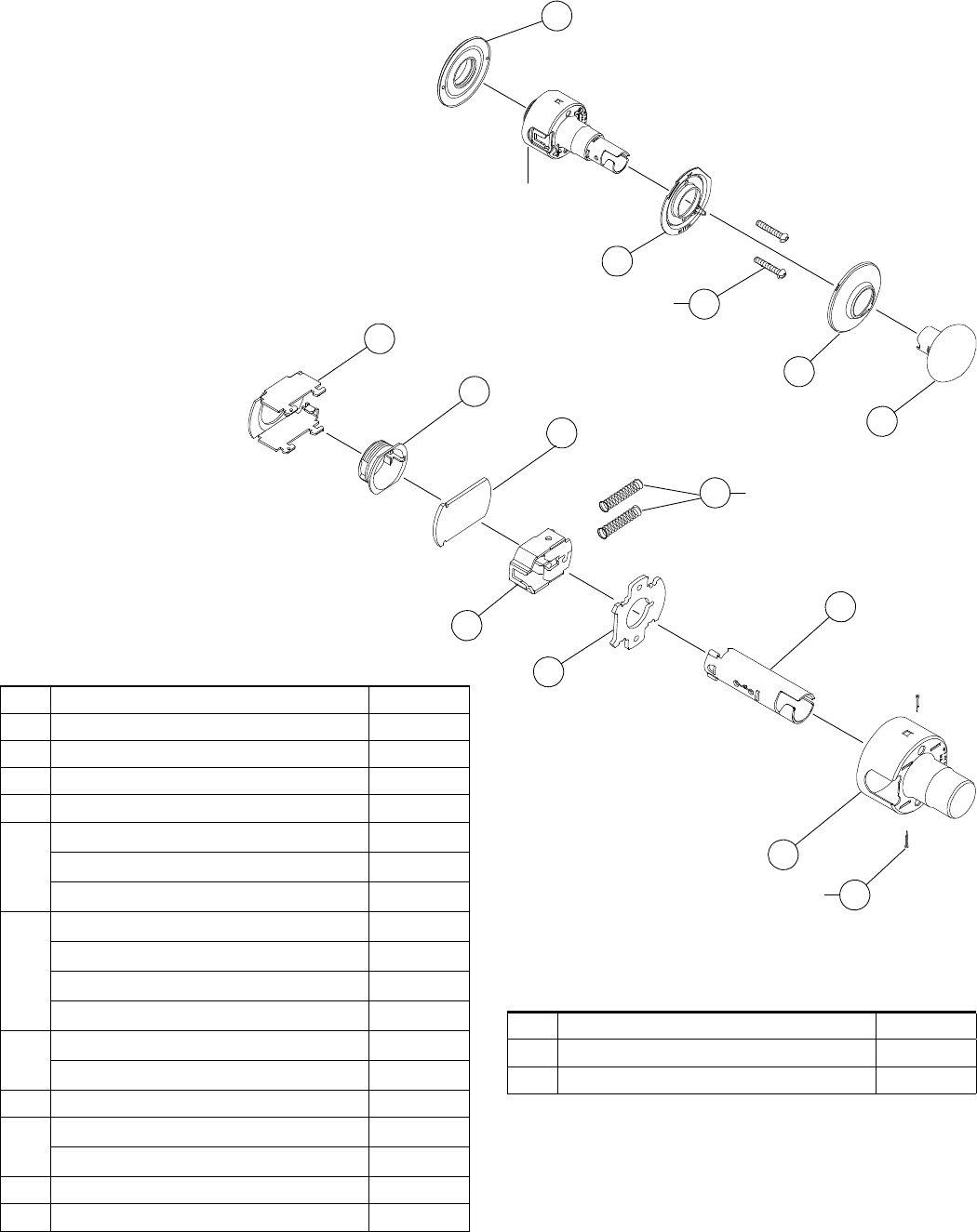
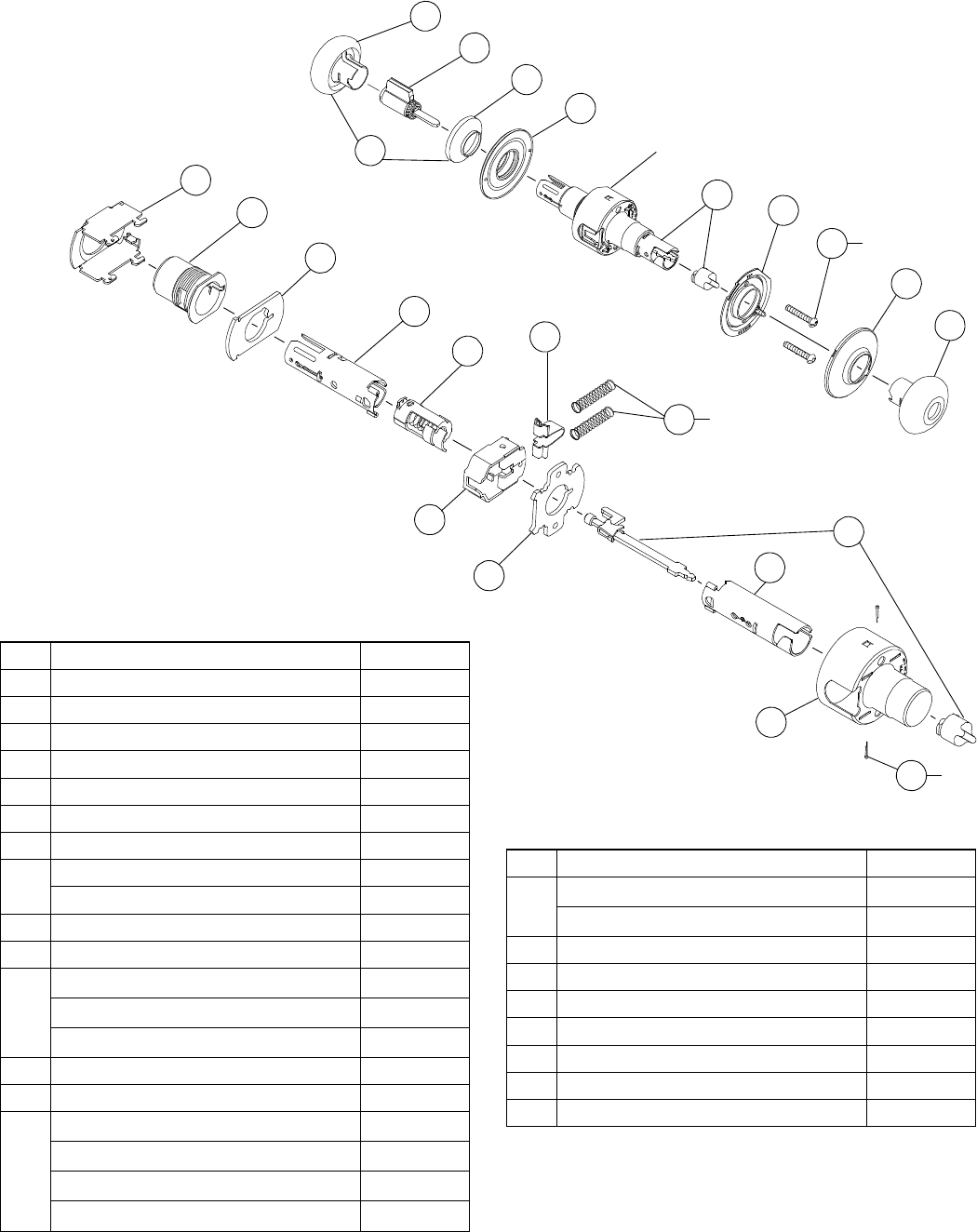
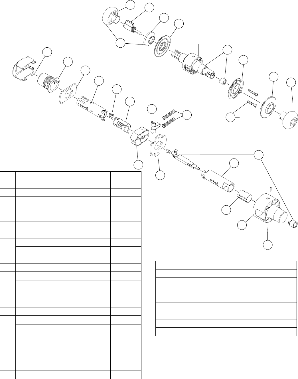
Chassis and Assemblies
Passage Lock
A10S
Chassis assembly
Trim assembly
Assembled
chassis
1
3
19
36
3
2
66
28
24
58
37
65
67
25
54
56
21
2
2
2
No. Description Part No.
1Rose, Outside 01-001**
2Rose, Inside 01-002**
3Knob/Lever, Closed 01-008**
19 Mounting Plate, Inside A201-377
21 Hub & Cap, Outside A201-406*
24 Spindle & Catch, Inside 1C\, - 1M\," door A301-386
Spindle & Catch, Inside 2 - 2Z\v" door A301-409
Spindle & Catch, Inside 2Z\x" door A301-410
25 Spindle & Catch, Outside A301-387
28 Housing & Cap, 1C\, - 1M\," door A301-403*
Housing & Cap, 2 - 2Z\v" door A301-404*
Housing & Cap, 2Z\x" door A301-405*
Housing Threaded, 1Z\, - 1M\," door A301-406*
36 Screw, Mtg. 1C\, - 1M\," door A501-161
Screw, Mtg. 2 -2Z\x" door A501-818
37 Plate, Inside A501-305
54 Plate, Outside A508-399
56 Frame A508-598
No. Description Part No.
58 Spring, Slide, Knob & Lever A508-605
65 Slide, Non-restoring A590-181
66 Cotter Pin C503-008
67 Plug, Spindle G570-232
* Specify finish
** Specify design and finish
Note: Parts for doors 2 - 2Z\x" thick are for doors extended inside (EI)
only.
Chassis and Assemblies
Schlage • A-Series service manual • 9
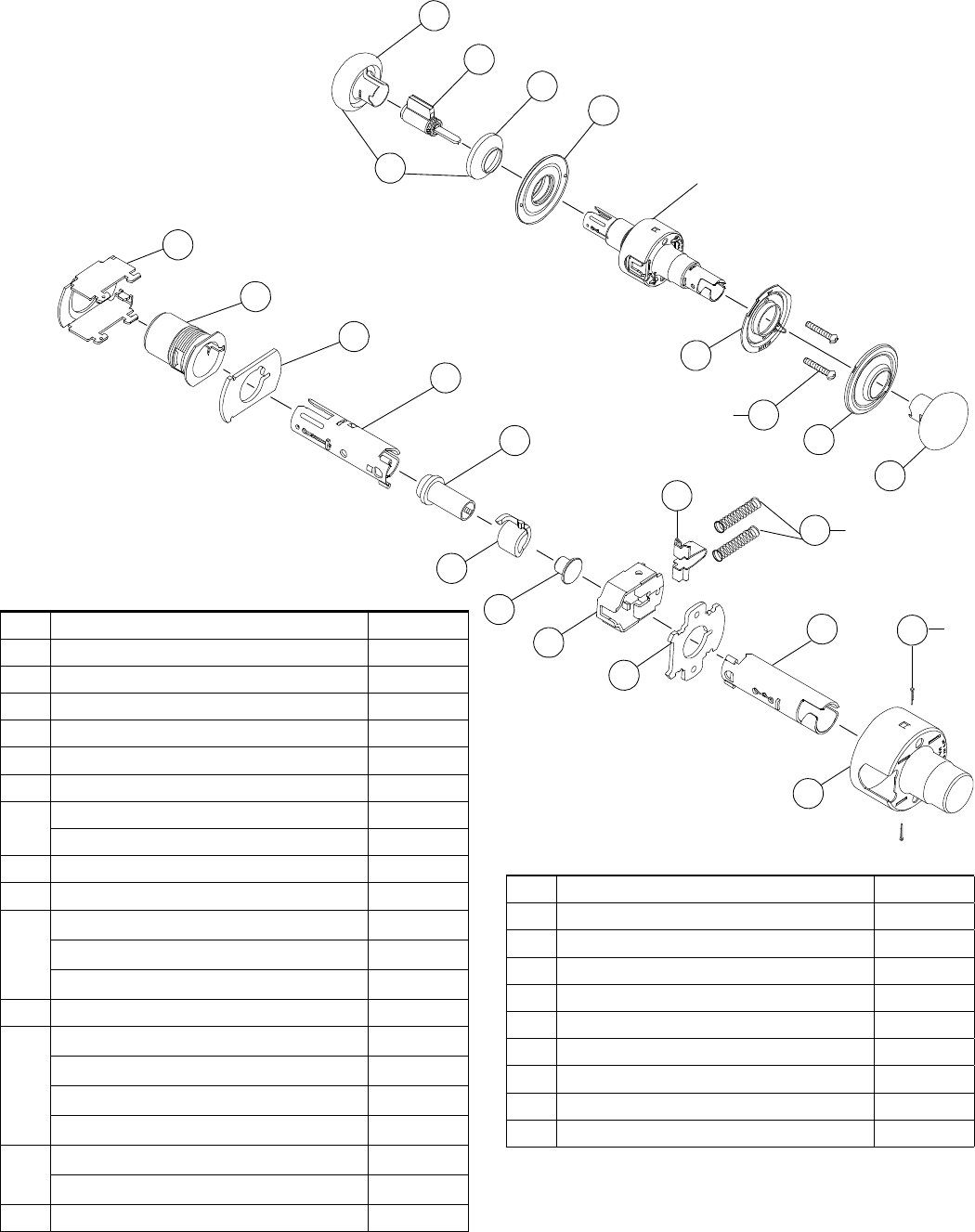
Exit Lock
A25D
Chassis assembly
Trim assembly
Assembled
chassis
56
38
52
65
37
58
24
28
66
22
19
36
2
3
2
2
2
No. Description Part No.
2Rose, Inside 01-002**
3Knob/Lever, Closed 01-008**
19 Mounting Plate, Inside A201-377
22 Rose, Outside A201-558*
24 Spindle & Catch, Inside 1C\, - 1M\," door A301-386
Spindle & Catch, Inside 2 - 2Z\v" door A301-409
Spindle & Catch, Inside 2Z\x" door A301-410
28 Housing & Cap, 1C\, - 1M\," door A301-403*
Housing & Cap, 2 - 2Z\v" door A301-404*
Housing & Cap, 2Z\x" door A301-405*
Housing Threaded, 1Z\, - 1M\," door A301-406*
36 Screw, Mtg. 1C\, - 1M\," door A501-161
Screw, Mtg. 2 -2Z\x" door A501-818
37 Plate, Inside A501-305
38 Hub, 1C\, - 1Z\x" door A501-498
Hub, 1B\, -1M\," door A501-499
52 Plate, Outside A501-874
56 Frame A508-598
No. Description Part No.
65 Slide, Non-restoring A590-181
66 Cotter Pin C503-008
* Specify finish
** Specify design and finish
Note: Parts for doors 2 - 2Z\x" thick are for doors extended
inside (EI) only.
10 • Schlage • A-Series service manual
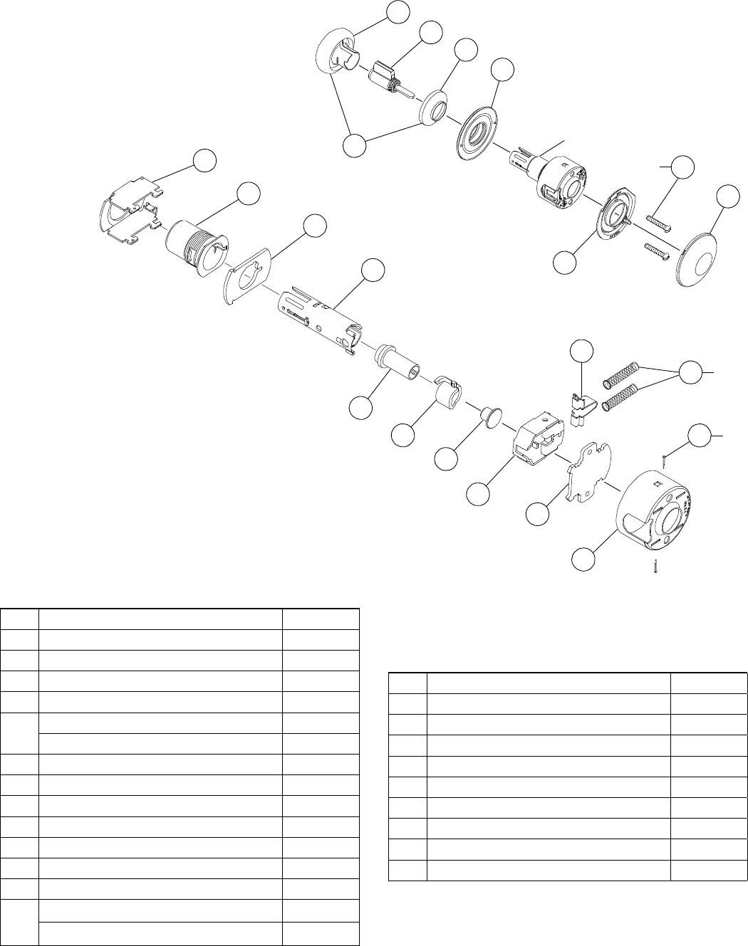
Chassis and Assemblies
Patio Lock
A30D
26
Chassis assembly
Assembled
chassis
Trim assembly
56
20
54
25
55
58
6
24
66
26
62
37
3
1
6
2
19
36
2
4
2
2
No. Description Part No.
1Rose, Outside 01-001**
2Rose, Inside 01-002**
3Knob/Lever, Closed 01-008**
4Knob/Lever, Open 01-009**
6Plunger & Button, Inside 01-055***
19 Mounting Plate, Inside A201-377
20 Hub and Cap, Outside A201-399*
22 Rose, Outside A201-558
24 Spindle & Catch, Inside C\, - 1M\," door A301-386
Spindle & Catch, Inside 2 - 2Z\v" door A301-409
Spindle & Catch, Inside 2Z\x" door A301-410
25 Spindle and Catch, Outside A301-403
28 Housing & Cap, 1C\, - 1M\," door A301-403*
Housing & Cap, 2 - 2Z\v" door A301-404*
Housing & Cap, 2Z\x" door A301-405*
Housing Threaded, 1Z\, - 1M\," door A301-406*
37 Plate, Inside A501-305
54 Plate, Outside A508-399
No. Description Part No.
55 Seat Spring, Knob & Lever A508-597
56 Frame A508-598
62 Slide, Restoring A590-158
55 Seat Spring, Knob & Lever A508-597
56 Frame A508-598
62 Slide, Restoring A590-158
* Specify finish
** Specify design and finish
*** Specify dimension and finish
Note: Parts for doors 2 - 2Z\x" thick are for doors extended inside (EI)
only.
Chassis and Assemblies
Schlage • A-Series service manual • 11
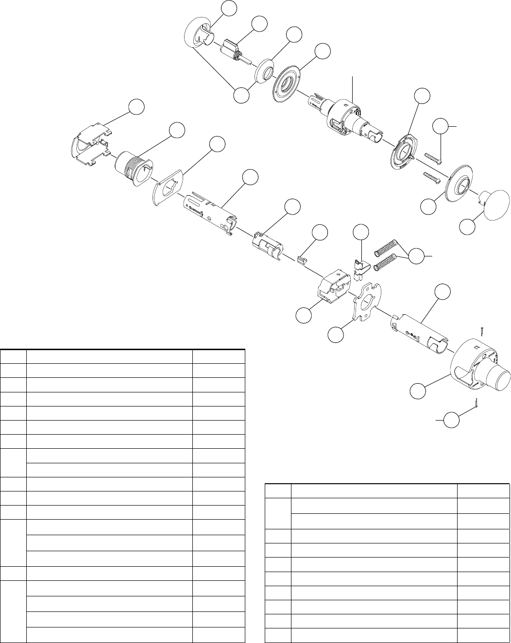
Bath/Bedroom Privacy Lock
A40S
Chassis assembly
Assembled
chassis
Trim assembly
236
4
8
1
7
19
4
2
56
21
54
25
27
64
37
58 2
7
24
28
66 2
No. Description Part No.
1Rose, Outside 01-001**
2Rose, Inside 01-002**
4Knob/Lever, Open 01-009**
7Plunger & Button, Inside 01-056***
8Plunger & Button, Outside 01-057***
19 Mounting Plate, Inside A201-377
21 Hub and Cap, Outside A201-406*
24 Spindle & Catch, Inside 1C\, - 1M\," door A301-386
Spindle & Catch, Inside 2 - 2Z\v" door A301-409
Spindle & Catch, Inside 2Z\x" door A301-410
25 Spindle and Catch, Outside A301-403
27 Cam, Outside A301-402
28 Housing & Cap, 1C\, - 1M\," door A301-403*
Housing & Cap, 2 - 2Z\v" door A301-404*
Housing & Cap, 2Z\x" door A301-405*
Housing Threaded, 1Z\, - 1M\," door A301-406*
36 Screw, Mtg. 1C\, - 1M\," door A501-161
Screw, Mtg. 2 - 2Z\x" door A501-818
No. Description Part No.
37 Plate, Inside A501-305
54 Plate, Outside A508-399
56 Frame A508-598
58 Spring Slide, Knob & Lever A508-605
64 Slide, Restoring A590-180
66 Cotter Pin C503-008
* Specify finish
** Specify design and finish
*** Specify dimension and finish
Note: Parts for doors 2 - 2Z\x" thick are for doors extended inside (EI)
only.
12 • Schlage • A-Series service manual
Chassis and Assemblies
Communicating Lock
A43D
58
Chassis assembly
Assembled
chassis
Trim assembly
56
21
54
23
58
2
60
4
2
59
9
41
57
66
2
37
63
1
68
No. Description Part No.
1Rose, Outside 01-001**
4Knob/Lever, Open 01-009**
9Plunger and Button, Outside 01-058***
21 Hub and Cap, Outside A201-406*
23 Turn and Plate, Inside A201-688*
37 Plate, Inside A501-305
41 Spindle, Inside, 1C\, - 1M\," door A501-633
Spindle, Inside, 2Z\v" door A500-001
Spindle, Inside, 2Z\x" door A500-002
54 Plate, Outside A508-399
56 Frame A508-598
57 Housing A508-600
58 Spring Slide, Knob & Lever A508-605
59 Stop Slide A508-641
No. Description Part No.
60 Screw, Mtg. 1C\, - 1M\," door A508-649*
Screw, Mtg. 2 - 2Z\x" door A508-650*
63 Slide, Non-restoring A590-159
66 Cotter Pin C503-008
68 Tamper Resistant Torx Tool Bit (One per case) M504-426
* Specify finish
** Specify design and finish
*** Specify dimension and finish
Note: Parts for doors 2 - 2Z\x" thick are for doors extended inside (EI)
only.
Chassis and Assemblies
Schlage • A-Series service manual • 13
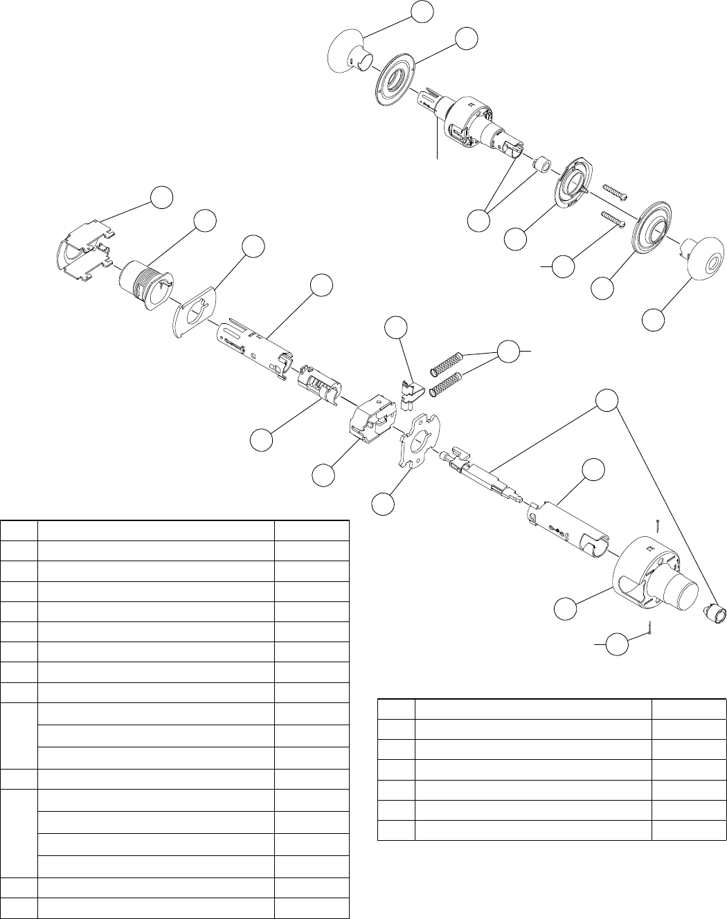
Entrance Lock
A53PD
Chassis assembly
Assembled
chassis
Trim assembly
56
20
54
63
58
4
2
66
37
25
55
27
28
24
10
2
36
19
10
1
13
5
14
12
2
2
No. Description Part No.
1Rose, Outside 01-001**
2Rose, Inside 01-002**
4Knob/Lever, Open 01-009**
5Knob and Sleeve, Cylinder 01-018**
10 Plunger & Button, Inside 01-060***
12 Cylinder Knob (less sleeve) 01-080**
13 Sleeve Knob Cylinder 01-081**
14 Cylinder, 6-Pin 21-002**
Cylinder, 6-Pin, Orbit 21-002-122**
19 Mounting Plate, Inside A201-377
20 Hub and Cap, Outside A201-399
24 Spindle & Catch, Inside 1C\, - 1M\," door A301-386
Spindle & Catch, Inside 2 - 2Z\v" door A301-409
Spindle & Catch, Inside 2Z\x" door A301-410
25 Spindle and Catch, Outside A301-387
27 Cam, Outside A301-402
28 Housing & Cap, 1C\, - 1M\," door A301-403*
Housing & Cap, 2 - 2Z\v" door A301-404*
Housing & Cap, 2Z\x" door A301-405*
Housing Threaded, 1Z\, - 1M\," door A301-406*
No. Description Part No.
36 Screw, Mtg. 1C\, - 1M\," door A501-161
Screw, Mtg. 2 - 2Z\v" door A501-818
37 Plate, Inside A501-305
54 Plate, Outside A508-399
55 Seat Spring, Knob and Lever A508-597
56 Frame A508-598
58 Spring Slide, Knob and Lever A508-605
63 Slide, Non-restoring A590-159
66 Cotter Pin C503-008
* Specify finish
** Specify design and finish
*** Specify dimension and finish
Note: Parts for doors 2 - 2Z\x" thick are for doors extended inside (EI)
only.
14 • Schlage • A-Series service manual
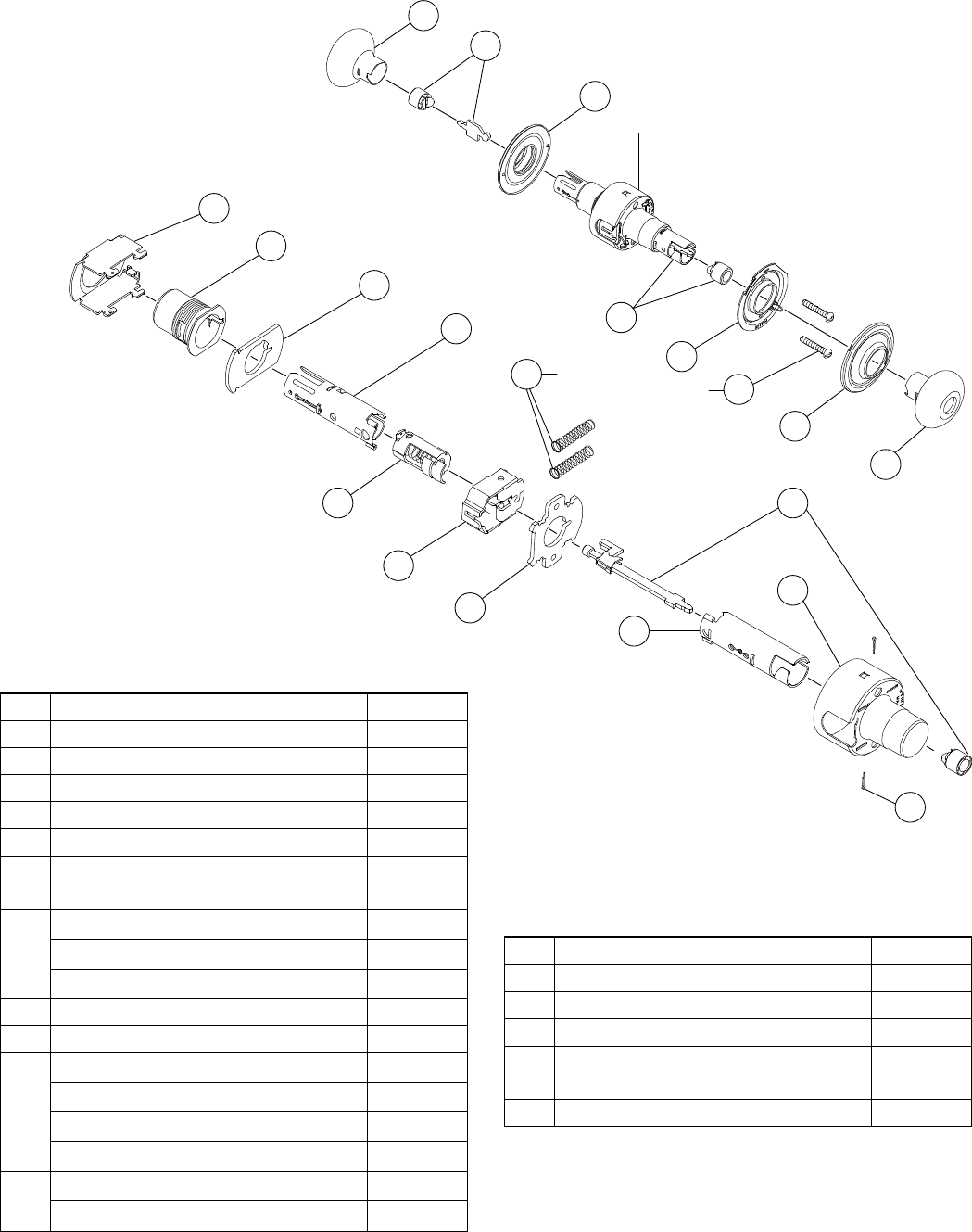
Chassis and Assemblies
Classroom Lock
A70PD
Assembled
chassis
Chassis assembly
Trim assembly
58
56
20
54
63
2
2
66
37
25
55
28
24
36
19
1
13
14
12
2
2
3
5
43
49
50
No. Description Part No.
1Rose, Outside 01-001**
2Rose, Inside 01-002**
3Knob/Lever, Closed 01-008**
5Knob and Sleeve, Cylinder 01-018**
12 Cylinder Knob (less sleeve) 01-080**
13 Sleeve Knob Cylinder 01-081**
14 Cylinder, 6-Pin 21-002*
Cylinder, 6-Pin, Orbit 21-002-122*
19 Mounting Plate, Inside A201-377
20 Hub and Cap, Outside A201-399*
24 Spindle & Catch, Inside 1C\, - 1M\," door A301-386
Spindle & Catch, Inside 2 - 2Z\v" door A301-409
Spindle & Catch, Inside 2Z\x" door A301-410
25 Spindle and Catch, Outside A301-387
28 Housing & Cap, 1C\, - 1M\," door A301-403*
Housing & Cap, 2 - 2Z\v" door A301-404*
Housing & Cap, 2Z\x" door A301-405*
Housing Threaded, 1Z\, - 1M\," door A301-406
36 Screw, Mtg. 1C\, - 1M\," door A501-161
Screw, Mtg. 2 - 2Z\v" door A501-818
37 Plate, Inside A501-305
No. Description Part No.
43 Plug, Cam A501-721
49 Spiral Cam A501-776
50 Spacer Cam A501-791
54 Plate, Outside A508-399
55 Seat Spring, Knob and Lever A508-597
56 Frame A508-598
58 Spring Slide, Knob and Lever A508-605
63 Slide, Non-restoring A590-159
66 Cotter Pin C503-008
* Specify finish
** Specify design and finish
Note: Parts for doors 2 - 2Z\x" thick are for doors extended inside (EI)
only.
Chassis and Assemblies
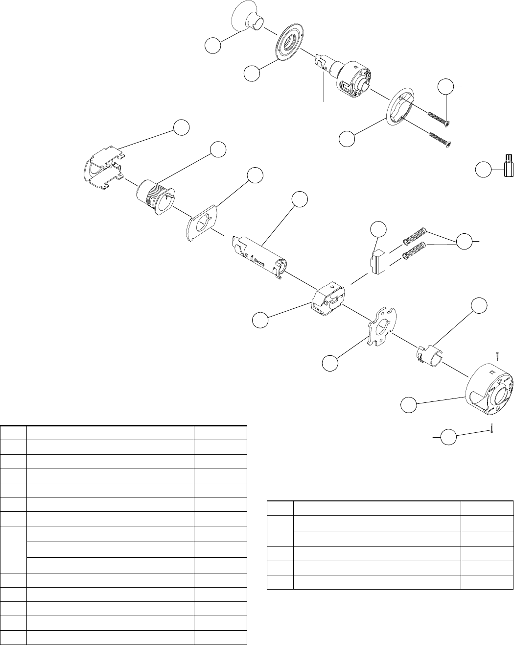
Schlage • A-Series service manual • 15
Communicating Lock
A79PD
Assembled
chassis
Chassis assembly
Trim assembly
47
45
1
13
14
12
2
5
44
58
56
20
54
63
2
66
57
25
55
46
2
43
49
50
No. Description Part No.
1Rose, Outside 01-001**
5Knob and Sleeve, Cylinder 01-018**
12 Cylinder Knob (less sleeve) 01-080**
13 Sleeve Knob Cylinder 01-081**
14 Cylinder, 6-Pin 21-002*
Cylinder, 6-Pin, Orbit 21-002-122*
19 Mounting Plate, Inside A201-377
20 Hub and Cap, Outside A201-399*
25 Spindle and Catch, Outside A301-387
43 Plug, Cam A501-721
44 Rose, Inside A501-766*
45 Plate, Mounting A501-767
46 Plate, Inside A501-768
47 Screw, Mtg. 1C\, - 1M\," door A501-769
Screw, Mtg. 2 - 2Z\v" door A501-770
No. Description Part No.
49 Spiral Cam A501-776
50 Spacer Cam A501-791
54 Plate, Outside A508-399
55 Seat Spring, Knob and Lever A508-597
56 Frame A508-598
57 Housing A508-600
58 Spring Slide, Knob and Lever A508-605
63 Slide, Non-restoring A590-159
66 Cotter Pin C503-008
* Specify finish
** Specify design and finish
Note: Parts for doors 2 - 2Z\x" thick are for doors extended inside (EI)
only.
16 • Schlage • A-Series service manual
Chassis and Assemblies
Storeroom Lock
A80PD
Chassis assembly
Assembled
chassis
Trim assembly
56
20
53
63
58 2
66
37
12
55
14
28
24
18
2
25
40
13
1
5
2
3
36
19
2
No. Description Part No.
1Rose, Outside 01-001**
2Rose, Inside 01-002**
3Knob/Lever, Closed 01-005**
5Knob and Sleeve, Cylinder 01-018**
12 Cylinder Knob (less sleeve) 01-080**
13 Sleeve Knob Cylinder 01-081**
14 Cylinder, 6-Pin 21-002*
Cylinder, 6-Pin, Orbit 21-002-122*
18 Cam A201-370
19 Mounting Plate, Inside A201-377
20 Hub and Cap, Outside A201-399*
24 Spindle and Catch, Inside, 1C\, - 1M\," door A301-386
Spindle and Catch, Inside, 2 - 2Z\v" door A301-409
Spindle and Catch, Inside, 2Z\x" door A301-410
25 Spindle and Catch, Outside A301-387
28 Housing & Cap, 1C\, - 1M\," door A301-403
Housing & Cap, 2 - 2Z\v" door A301-404
Housing & Cap, 2Z\x" door A301-405
Housing, Threaded, 1C\, - 1M\," door A301-406
No. Description Part No.
36 Screw, Mtg. 1C\, - 1M\," door A501-161
Screw, Mtg. 2 - 2Z\x" door A501-818
37 Plate, Inside A501-305
40 Wedge A501-615
53 Plate, Outside A501-901
55 Seat Spring, Knob and Lever A508-597
56 Frame A508-598
58 Spring Slide, Knob and Lever A508-605
63 Slide, Non-restoring A590-159
66 Cotter Pin C503-008
Chassis and Assemblies
Schlage • A-Series service manual • 17
Faculty/Restroom Lock
A85PD
Chassis assembly
Assembled
chassis
Trim assembly
56
20
53
62
58 2
66
37
12
55
15
27
24
11
2
25
40
13
1
5
2
4
36
19
2
28
42
11
No. Description Part No.
1Rose, Outside 01-001**
2Rose, Inside 01-002**
4Knob/Lever, Open 01-009**
5Knob and Sleeve, Cylinder 01-018**
11 Plunger and Button, Inside 01-063***
12 Cylinder Knob (less sleeve) 01-080**
13 Sleeve Knob Cylinder 01-081**
15 Indicator Cylinder 21-003*
Indicator Cylinder, Orbit 21-003-168*
19 Mounting Plate, Inside A201-377
20 Hub and Cap, Outside A201-399*
24 Spindle and Catch, Inside, 1C\, - 1M\," door A301-386
Spindle and Catch, Inside, 2 - 2Z\v" door A301-409
Spindle and Catch, Inside, 2Z\x" door A301-410
25 Spindle and Catch, Outside A301-387
27 Cam, Outside A301-402
28 Housing & Cap, 1C\, - 1M\," door A301-403*
Housing & Cap, 2 - 2Z\v" door A301-404*
Housing & Cap, 2Z\x" door A301-405*
Housing, Threaded, 1C\, - 1M\," door A301-406*
36 Screw, Mtg. 1C\, - 1M\," door A501-161
Screw, Mtg. 2 - 2Z\x" door A501-818
37 Plate, Inside A501-305
No. Description Part No.
40 Wedge A501-615
42 Sleeve, Swivel A501-710
53 Plate, Outside A501-901
55 Seat Spring, Knob and Lever A508-597
56 Frame A508-598
58 Spring Slide, Knob and Lever A508-605
62 Slide, Restoring A590-158
66 Cotter Pin C503-008
* Specify finish
** Specify design and finish
*** Specify dimension and finish
Notes: Parts for doors 2 - 2Z\x" thick are for doors extended inside (EI)
only. Faculty/Restroom function locks are funished 0-bitted with
two 6-pin key unless otherwise specified. Emergency keys must
be ordered separately.
18 • Schlage • A-Series service manual
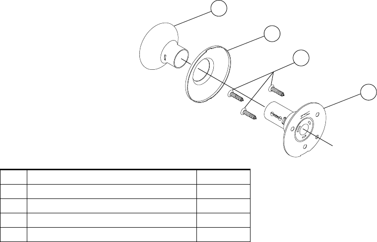
Chassis and Assemblies
Dummy Trim
A170
3
70
69
2
No. Description Part No.
2Rose, Inside 01-002**
3Knob/Lever, Closed 01-005**
69 Non-Threaded Chassis, Less Knob and Rose A201-330
70 Screws, Mtg. C603-897
* Specify finish
** Specify design and finish
*** Specify dimension and finish
Note: Parts for doors 2 - 2Z\x" thick are for doors extended inside (EI) only.

20 • Schlage • A-Series service manual
Parts and Accessories
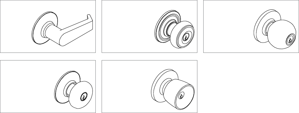
Knob and Lever Designs
Wrought brass, bronze or stainless steel. Lever is zinc based, plated to match BHMA symbols.
Levon (LEV)
Available Finishes:
605, 612, 613,
626
Georgian (GEO)
Available Finishes: 605,
606, 609, 610, 625, 626
Orbit (ORB)
Available Finishes: 605,
606, 609, 610, 611, 612,
613, 616, 625, 626
Plymouth (PLY)
Available Finishes: 605, 606,
609, 610 611, 612, 613, 616,
625, 626, 629, 630
Tulip (TUL)
Available Finishes: 605,
606, 609, 610, 625, 626
Parts and Accessories
Schlage • A-Series service manual • 21
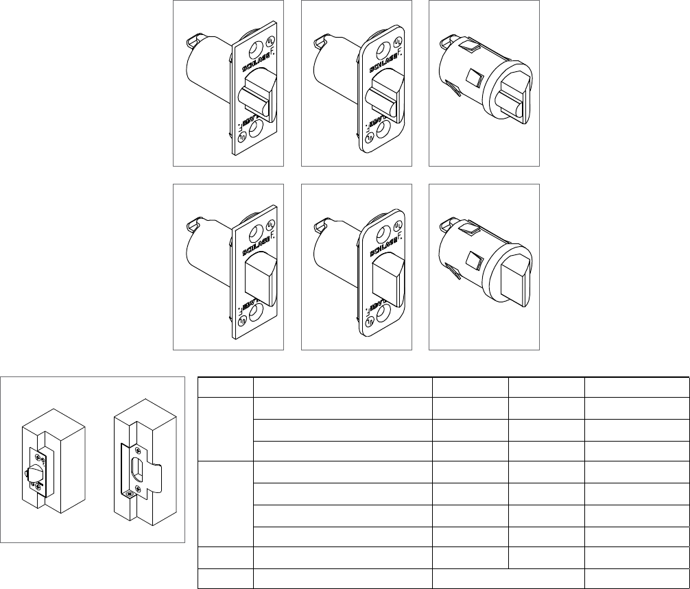
Latches
All A-Series latches have adjustable brass or bronze faceplates for flat or beveled doors, Z\x" throw standard.
Deadlatch
11-085
Deadlatch
11-088
Deadlatch
11-104
Springlatch
11-068
Springlatch
11-069
Springlatch
11-110
Rabbeted Latch and Strike Kit*
39-030
Backset Description Deadlatch Springlatch Housing Diameter
2C\,"Square corner, standard 1" x 2Z\v"11-085 11-068 M\,"
Z\v" Radius round corner, 1" x 2Z\v" 11-088 11-069 M\,"
1" Circular drive-in (non-UL) 11-104 11-110 1"
2C\v"Square corner, 1" x 2Z\v"11-091 11-111 M\,"
Square corner, 1Z\," x 2Z\v"11-096 11-116 1"
Z\v" Radius round corner, 1" x 2Z\v"11-092 11-112 M\,"
1" Circular drive-in (non-UL) 11-105 11-113 1"
3C\v"Square corner, 1Z\," x 2Z\v"14-010 14-028 1"
Rabbeted latch and strike kit 39-030* —
* This kit adapts square corner latch and 2C\v" high square corner strike to Z\x" rabbeted door and frame preparations.
22 • Schlage • A-Series service manual
Parts and Accessories
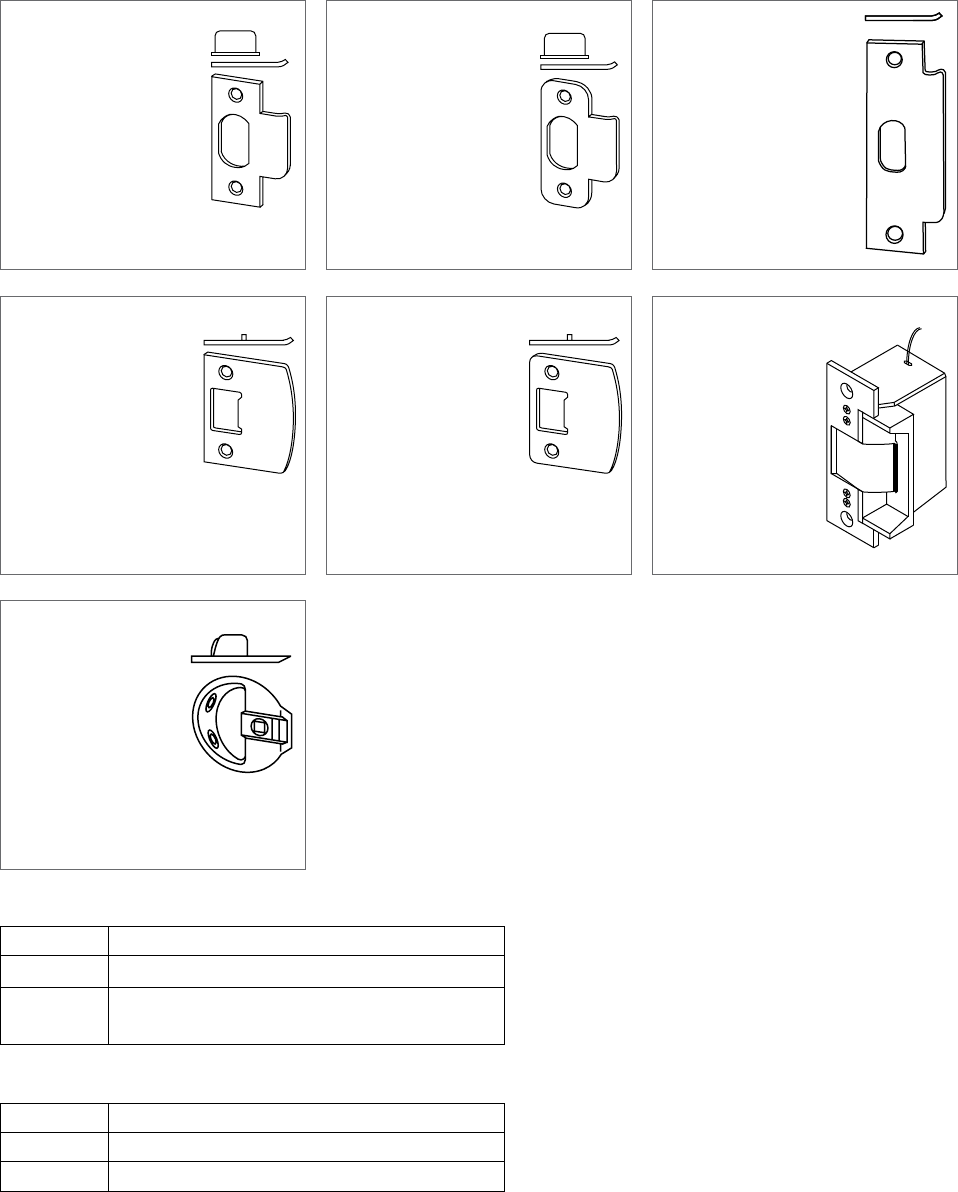
Strikes
10-001 (Standard)
Square Corner
Size: 1Z\," x 2C\v" x C\cx"
Lip Length: 1Z\," ISIdi. 1",
1Z\v", 1Z\x", 1C\v", 2"
Includes C603-623 strike
box
10-004
Z\v" Radius Round Corner
Size: 1Z\," x 2C\v" x C\cx"
Lip Length: 1Z\,"
Includes C603-623 strike
box
10-025
ANSI Prep. A115.2
Size: 1Z\v" x 4M\," x C\cx"
Lip Length: 1C\zn" (Std.) 1C\,"
If required, K510-066 strike
box must be ordered
separately.
10-026
Full Lip, Square Corner
Size: 1B\," x 2Z\v" x C\zn"
Lip Length: 1Z\,"
10-027
Full Lip, Z\v" Radius Round
Corner, No Box
Size: 1Z\," x 2C\v" x C\cx"
Lip Length: 1Z\,"
10-042
Electric Strike
Size: 1Z\v" x 4M\," x C\cx"
Voltage: 24 VAC, 12
VDC
Not designed for
continuous duty and
electrical locking.
606, 626 only
10-058
Circular Adjustable
Size: 1C\v" diameter
Lip Length: 1M\cx"
Optional tamper resistant torx screw packs
Part No. Description
C203-311 (4) Latch and Strike Screws, #8-32 x Z\x" (T-15)
C203-312 (2) Latch Screws, #8-32 x Z\x" (T-15)
(2) ANSI Strike Screws, #12-24 x Z\x" (T-20)
Torx tools
Part No. Description
M504-425 T-15 Torx Tool
M504-426 T-20 Torx Tool

Parts and Accessories
Schlage • A-Series service manual • 23
Finishes
Schlage Lock finishes are durable, top quality finishes obtained by the careful processing of solid brass, bronze, stainless
steel, or other materials. When required, a protective clear coating is applied and cured under high temperature. It is
important that climatic conditions and usage be taken under consideration when selecting finishes. This is especially true in
areas subjected to strong corrosive vapors, humid climate, or sea air, which, in a short time, may have a damaging effect on
metal finishes.
The longevity and preservation of the finish appearance is determined by base metal and finishing process. Clear protective
coating or other organic finishing applications may require different methods of cleaning and care. As an example, non-clear
coated finishes should not be cleaned with soaps or any solvents; organically coated surfaces should periodically be cleaned
with a mild non-abrasive soap and buffed lightly with a clean cloth. The type of base metal and finishing techniques must be
considered when applying any cleaning or preservative method. Contact the Schlage Technical Services Department for
further information on the care of finished hardware.
In some instances, for customer convenience, the most appropriate BHMA (Builders Hardware Manufacturers Association)
finish symbols are used to indicate similarity of appearance regardless of base metal or finishing process. A-Series levers are
zinc based material and are plated to match finishes indicated. Finish numbers in the 600-Series are the BHMA industry
standard. The nearest old U.S. equivalent code designations are shown in parentheses ( ).
Code Description
605 US (3) Bright Brass, Clear Coated
606 US (4) Satin Brass, Clear Coated
609 US (5) Satin Brass, Blackened Satin Relieved, Clear
Coated
610 US (7) Bright Brass, Blackened Bright, Relieved, Clear
Coated
611 US (9) Bright Bronze
612 US (10) Satin Bronze, Clear Coated
613 US (108) Oil Rubbed Bronze, Oxidized Satin, Bronze, Oil
Rubbed, No Coating
616 US (11) Antique Bronze
625 US (26) Bright Chromium Plated, No Coating
626 US (260) Satin Chromium Plated, No Coating
630 US (320) Satin Stainless Steel, No Coating
24 • Schlage • A-Series service manual
Parts and Accessories
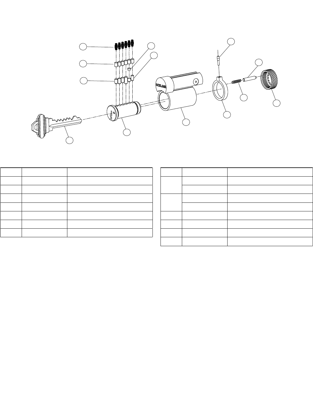
Cylinder Units and Parts
Schlage locks are provided with cylinder units precision built to extremely close tolerances and the highest standards of
accuracy. Phosphor bronze springs, nickel silver keys, and pins are used throughout the Schlage offering. The best
combination of materials is used to ensure the manufacture of cylinders with ease of operation and long wear. To order locks
less cylinder units, change product sux letter "P" and "L". Example: A53LD. Primus® cylinders are available when key
control and physical security are important concerns.
Cylinder Units
Standard
Cylinders
Primus Cylinders Descriptions Design
High Security Controlled Access XP
21-002 20-524 20-724 20-524-XP 20-724-XP 6 Pin unit All except ORB, COM,
PLA
21-002-122 20-524-122 20-724-122 20-524-122-XP 20-724-122-XP 6 Pin unit
(except A73 & A85)
ORB, COM, PLA
21-002-149 20-524-149 20-724-149 20-524-149-XP 20-274-149-XP 6 Pin unit (A73) ORB, COM, PLA
21-003 Not Available 6 Pin Indicator unit (A83) All except ORB, COM,
PLA
21-003-168 6 Pin indicator unit (A83) ORB, COM, PLA
21-002
Standard
Cylinder
21-003
Hotel
Function
Indicator
Cylinder
20-524
Primus High
Security
U.L. 437
Listed
20-724
Primus
Controlled
Access
20-524-XP
Hotel Function
Indicator
Cylinder
20-724-XP
Standard
Cylinder
Hotel Function Indicator Cylinder
Hotel Function Indicator Cylinder w/ ORB Knob
Spacer
Important: Use only graphite or similar material
for cylinder lubrication. Under no
circumstances should any other type of
material be introduced into the cylinder.
Parts and Accessories
Schlage • A-Series service manual • 25
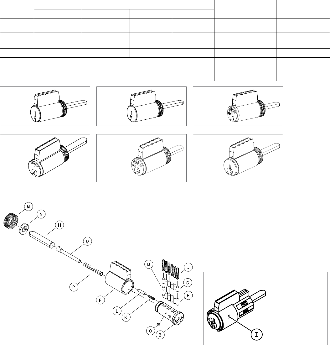
Cylinder Parts
Letter Part no. Description
A33-230 Cylinder plug, 6 pin for 21-002
B33-235 Cylinder plug, indicator, 6 pin for 21-003
C34-101 thru 103 #1 thru #3 Top pin
D34-202 thru 209 #2 thru #9 Master pin
E34-300 thru 309 #0 thru #9 Bottom pin
FA201-698 Body, 6 pin
GA201-934 Bar & driver for 21-002-149
A301-337 Bar & driver for 20-724, 20-724-XP, 20-524,
20-524-XP
A301-338 Bar & driver for 21-002-122
A301-339 Bar & driver A73 Orbit
A508-606 Bar & driver for 21-001, IDisc.1, & 21-002
A508-614 Bar & driver for 21-002-122
HA501-693 Bar for 21-003-168
A501-991 Bar for 21-003
IA508-640 Spacer for ORB knob
JC503-113 Tumbler spring
KC503-115 Retainer cap spring
LC503-116 Retainer cap pin
MC503-118 Retainer cap
NC503-767 Driver for 21-003
OC603-195 Obstruction pin for 21-003
C604-362 Obstruction pin, Everest
PC604-144 Indicator pin spring for 21-003
C604-369 Indicator pin spring, Everest
QC604-368 Indicator pin, Everest
SC604-371 Indicator pin for 21-003
TXA10-594 5 Pin cylinder extension to fit 6 pin knobs
(Requires A508-614 bar & driver)
Standard Cylinder
Standard Cylinder w/ ORB
Knob Spacer
5 Pin Cylinder to 6 Pin Knob
Conversion Parts
26 • Schlage • A-Series service manual
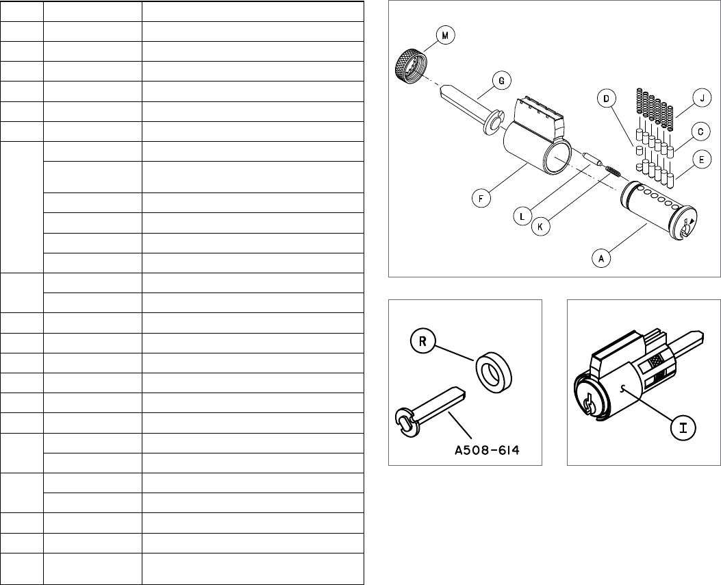
Parts and Accessories
Interchangeable Cores, Designs, and Parts
Available for all A-Series keyed functions, except Hotel/Motel function A85, as complete locks or in retrofit kits. Existing
installations can be retrofitted without removing lock from door. To order locks with interchangeable cores, change product
sux letter "P" to "R". Example: A53RD. To order locks less interchangeable cores, change product sux letter "P" to "J".
Example: A53JD. Primus® cores are available when key control and physical security are important concerns.
Interchangeable Cores
23-030
Interchangeable
Core w/ Logo
23-031
Interchangeable
Core w/o Logo
20-740
Primus
Interchangeable
Core w/ Logo,
Controlled
Access
20-741
Primus
Interchangeable
Core w/o Logo,
Controlled
Access
20-524-XP
Everest Primus
Interchageable
Core, UL
20-724-XP
Everest Primus
Interchageable
Core w/o Logo
Interchangeable Core Designs
Orbit
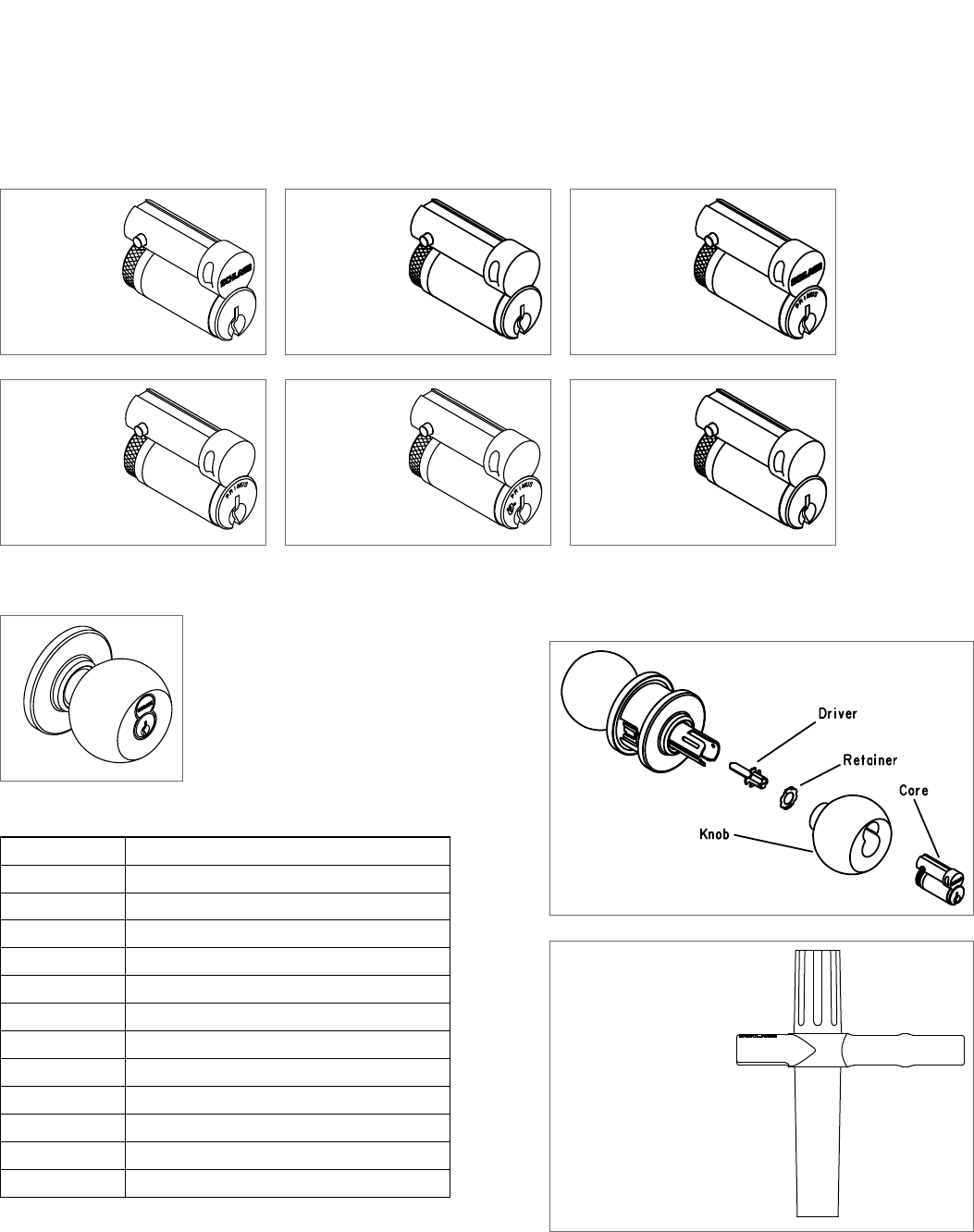
Interchangeable Core Accessory and Service Parts
Part no. Description
01-026 Knob only
01-053 Driver and retainer
01-054 Knob, core, driver, and retainer
20-524-122-XP Everest Primus Interchangeable Core, UL
20-724-122-XP Everest Primus Interchangeable Core w/o Logo
20-740 Primus interchangeable core w/ logo
20-741 Primus interchangeable core w/o logo
23-030 Interchangeable core w/ logo
23-031 Interchangeable core w/o logo
A501-941 Retainer
C604-307 Driver
M504-413 Installation tool
01-054 Retrofit Kit
M504-413
Installation Tool
Order as needed per project
Parts and Accessories
Schlage • A-Series service manual • 27
Interchangeable Core
To remove interchangeable core, insert control key and turn 15° to the right until action stops. Pulling on key will extract core
from the knob. To install a new core, insert control key and push core into housing, rotate key 15° to the right and insert core
completely. Rotate key back to original position and remove control key.
JD
Y
X
V
M
K
W
U
S
T
C
E
Interchangeable Core Parts
Letter Part no. Description
C34-101 thru 103 #1 thru #3 Top Pin
D34-202 thru 209 #2 thru #9 Master Pin
E34-300 thru 309 #0 thru #9 Bottom pin
JC503-113 Tumbler spring
KC503-115 Retainer cap spring
MC503-118 Retainer cap
S* 33-235 Plug, Everest interchangeable core
Letter Part no. Description
T 35-056 Control key, blank
48-056 Control key, cut
U* B220-282 Interchangeable core body, w/ logo
B220-283 Interchangeable core body, w/o logo
VC603-347 Retainer cap pin
W* C603-956 Actuating ring
X* C603-964 Actuating pin
Y* C603-967 Control pin
* Parts not compatible with cores manufactured before 1991.
Important: Use only graphite or similar material for cylinder lubrication. Under no circumstance should any other type of
material be introduced into the cylinder.
28 • Schlage • A-Series service manual
Parts and Accessories
Lubrication
A-Series lock mechanisms are designed for durability and seldom need servicing. During assembly, those points of contact
which require lubrication for ease of operation are given on application of high quality petroleum based grease. A touch of
graphite is applied to the pin tumbler plug during assembly of the cylinder unit. No further servicing should be required for an
extended period except where locks are subjected to extremely heavy trac. Also, if located in particularly dusty or dirty
areas, the grease may become contaminated resulting in a slow or otherwise unsatisfactory operation. The case mechanism
should then be cleaned in a non-corrosive petroleum solvent and relubricated. Graphite only should be applied to the
cylinder unit by blowing a small quantity into the keyway.
ÎNote: Precautionary measures according to solvent manufacturers instructions should always be followed.
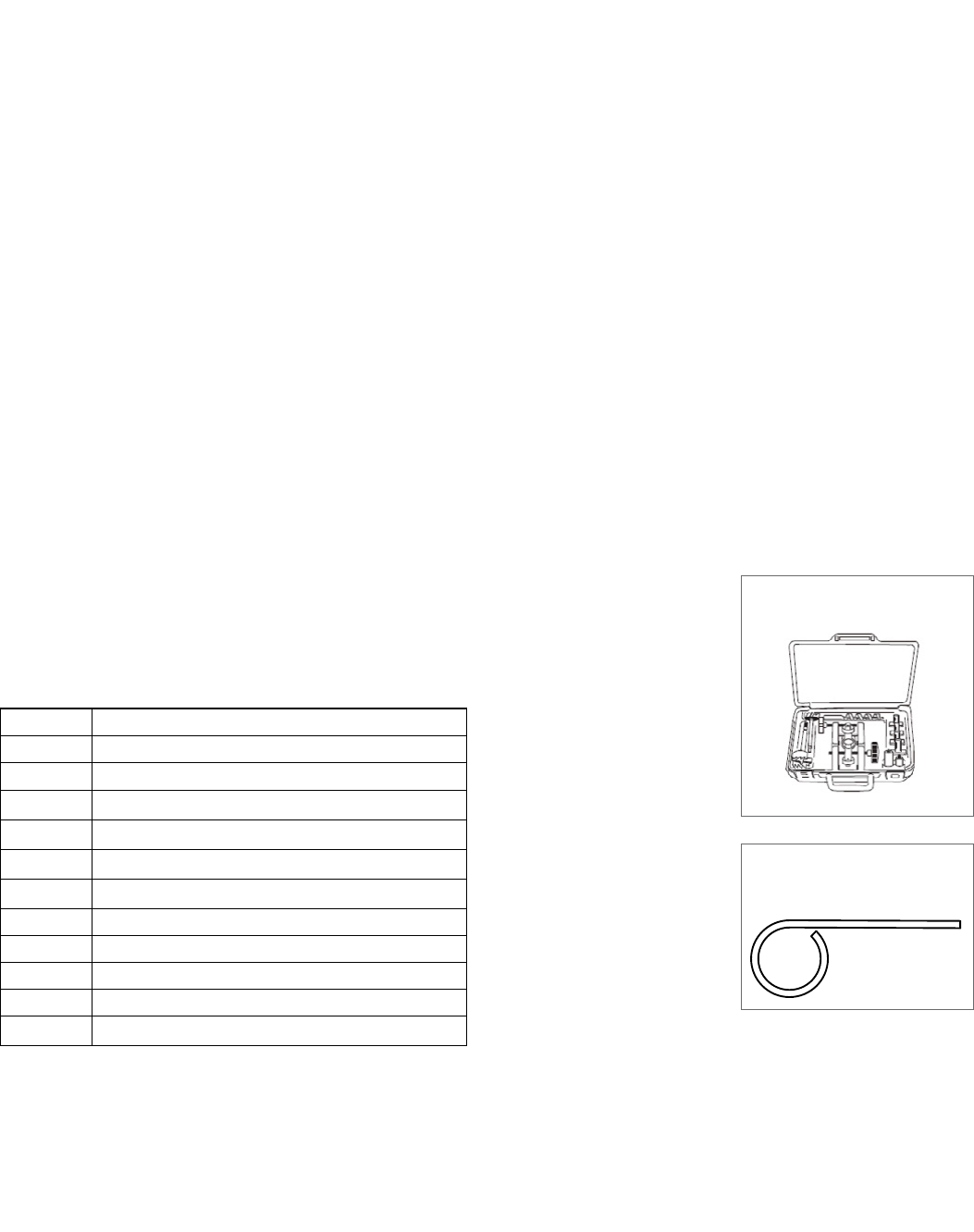
Installation Tools and Kits
Boring jig and tools are designed to provide fast and accurate lock installation. Complete kit
contained in a heavy gage metal box, or individual tools can be ordered for preparing doors
and jambs for Schlage products.
For A, AL, B, D, F, H, and S200-series locks. Adjustable for 2 C\," and 2 C\v" backsets. Designed
for special high speed hexagonal shank boring bits and equipped with an adaptor to form an
integrated unit for boring doors 1B\zn" to 1ZB\zn" thick.
Part No. Description
40-148 Installation JIG
M504-497 Case Only
40-176 2 Z\," Multi Spur Bit
40-177 1 Z\x" Multi Spur Kit
40-030 1 Z\," x 2 C\v" Strike Chisel
40-032 1 Z\," x 2 Z\v" Latch Chisel
40-175 1" Bit
40-178 Quick Change Bit Adapter
40-179 1" Strike Locator
40-029 Full Lip Strike Chisel
40-031 1 Z\," x 2 Z\v" Latch Chisel
40-147
Installation Kit
M504-271
Pin Wrench
For depressing knob catches on
A and D-Series locks.
Parts and Accessories
Schlage • A-Series service manual • 29
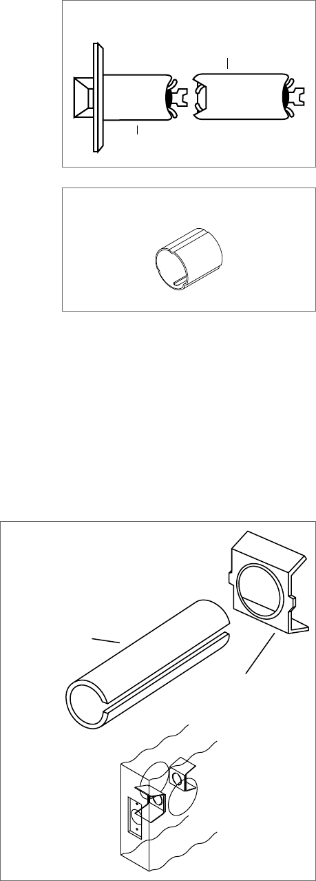
Long Backsets
Backsets 5" and over require extension links. A-Series locks with long backsets
are normally furnished with 1" faceplates and M\," housings. Links installed in 1"
latch holes require one G506-815 sleeve (order separately) to join latch and
link.
Reinforcement Kit
The Schlage 37-001 reinforcement kit is to reinforce and help prevent
the collapse of hollow metal doors when locksets are tightly
mounted. This kit should be used with long backsets for installations
in hollow metal doors to prevent lateral movement of latch bolt.
Specify door thickness 1C\," or 1C\v" when ordering.
41-005
5" Extension Link
Extension Link
2 ³⁄₈” Backset Latch
G506-815
Sleeve
37-001
Reinforcement Kit
Placement of
reinforcements in
hollow metal door.
Reinforcement
A501-565 - 1 ³⁄₈” doors
A501-566 - 1 ³⁄₄” doors
Sleeve
A501-567
30 • Schlage • A-Series service manual
Parts and Accessories
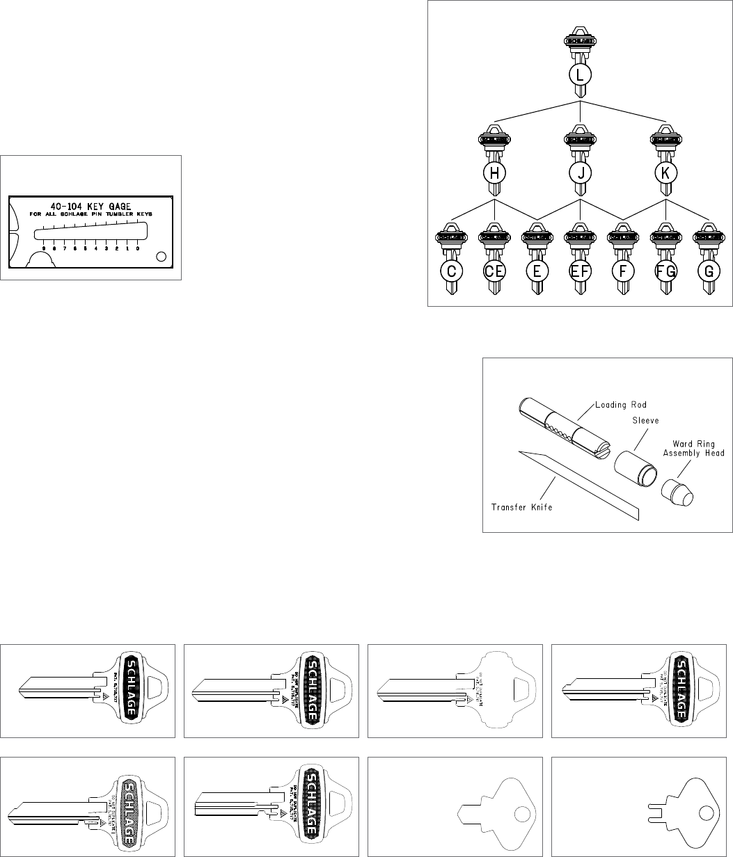
Keying
The Schlage Masterkey Department determines and makes the final
decision in the selection and use of key sections. Other keyways than
shown below are available. Allocation of other keyways is based on
need and extent of the final system. Priority is given to key systems that
require a large number of cylinders and families of key sections to
satisfy their keying requirements. Contact your Schlage representative
for availability of other keyways.
Order the Schlage key gage to accurately measure the depth of key
cuts.
Key Gage
40-104
Cylinder Body Loading Tool
A compact precision tool for loading top pins and springs and for installation of
ward rings into grooves of a worded cylinder plug. Furnished with complete
assembly instructions.
Pin Tumbler Keys
All Schlage locks come with two nickel silver keys as standard, embossed with our company logo. The nickel silver alloy from
which all Schlage keys are made provides the base for accuracy in cutting and long cylinder wear. Schlage will stamp "DO
NOT DUPLICATE" across the bow of all versions of its keys at no extra charge when specified on orders.
Embossed
35-009
Embossed*
35-002
Unembossed*
35-015
Embossed Control
35-003
Hotel Function Control*
35-016
Emergency, Blank*
35-007
Emergency Key A40 Function
35-250
Spanner Key A85 Function
35-251
* stamped with "Do Not Duplicate"
Key Array Chart
Cylinder Body Loading Tool
40-116
Allegion (NYSE: ALLE) creates peace of mind by pioneering safety and security.
As a $2 billion provider of security solutions for homes and businesses, Allegion
employs more than 7,800 people and sells products in more than 120 countries
across the world. Allegion comprises 23 global brands, including strategic
brands CISA®
, Interflex®
, LCN®
, Schlage® and Von Duprin®
.
For more, visit www.allegion.com.
About Allegion
© 2015 Allegion
006720, Rev. 02/15
www.allegion.com/us
