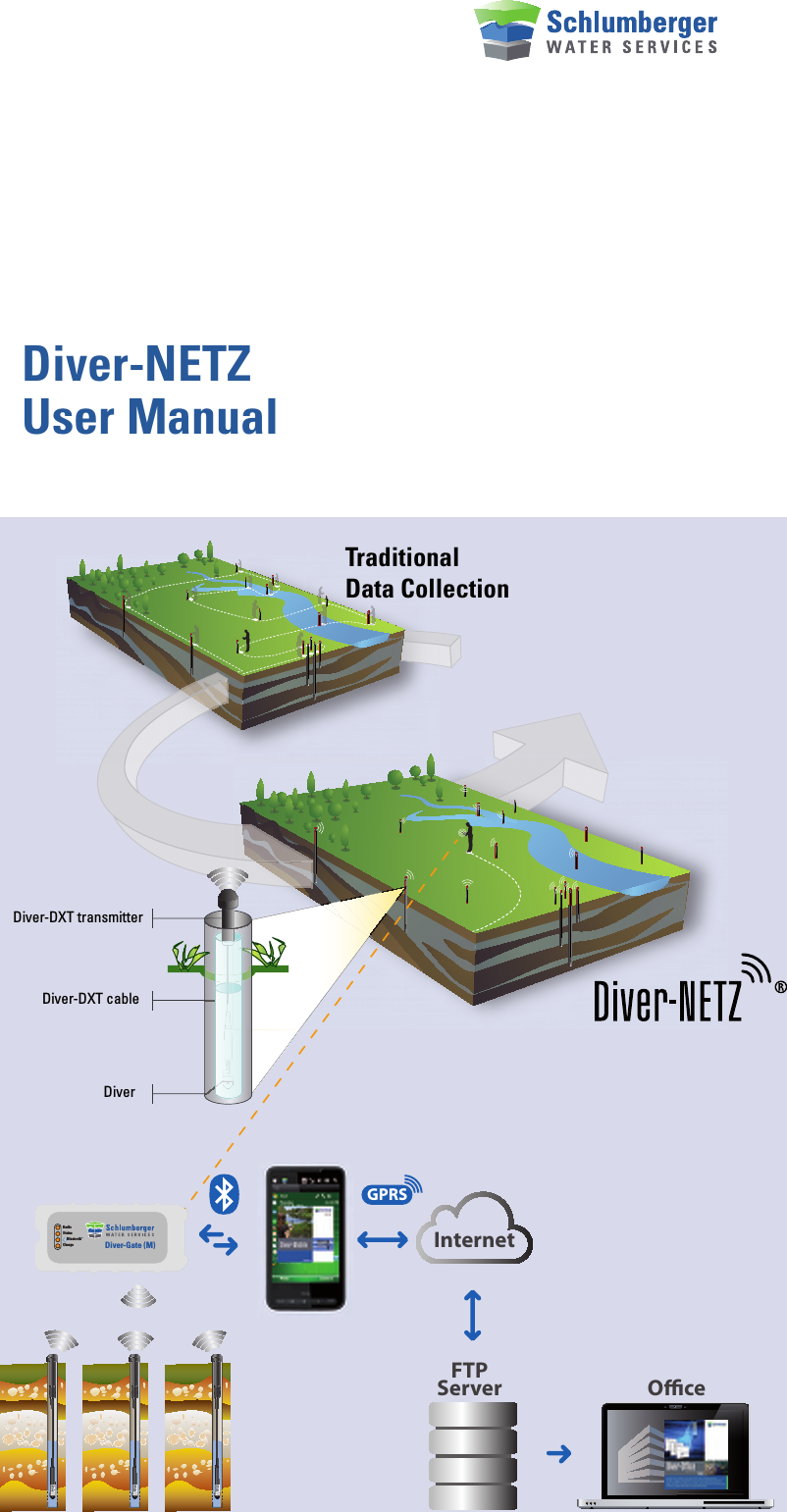
Schlumberger Water Services DIVERDXT2 Ground Water Monitoring Transmitter User Manual SWS productmanual indd

Schlumberger Water Services (Netherlands) bv Ground Water Monitoring Transmitter SWS productmanual indd

Manual

Diver-NETZUser Manual  TraditionalData CollectionDiver-DXT transmitterDiver-DXT cableDiverStatusRadioChargeBluetoothTMDiver-Gate (M)GPRSInternetFTPServer Oce
Diver-NETZUser ManualWARNING TO USERS IN THE UNITED STATESFederal Communication Commission Interference Statement 47 CFR Section 15.105(b)This equipment has been tested and found to comply with the limits for a Class B digital device, pursuant to Part 15 of the FCC Rules. These limits are designed to provide reasonable protection against harmful interference in a residential instal-lation. This equipment generates uses and can radiate radio frequency energy and, if not installed and used in accordance with the instructions, may cause harmful interference to radio communications. However, there is no guarantee that interfe-rence will not occur in a particular installation. If this equipment does cause harmful interference to radio or television reception, which can be determined by turning the equipment off and on, the user is encouraged to try to correct the interference by one of the following measures:- Reorient or relocate the receiving antenna.- Increase the separation between the equipment and receiver.- Connect the equipment into an outlet on a circuit different from that to which the receiver is connected.- Consult the dealer or an experienced radio/TV technician for help.This device (Diver-DXT) complies with Part 15 of the FCC Rules. Operation is subject to the following two conditions: (1) This device may not cause harmful interference, and (2) this device must accept any interference received, including interference that may cause undesired operation.NO UNAUTHORIZED MODIFICATIONS47 CFR Section 15.21CAUTION: This equipment may not be modified, altered, or changed in any way without signed written permission from Schlumberger Water Services (NL) bv. Unauthorized modification may void the equipment authorization from the FCC and will void the Schlumberger Water Services (NL) bv warranty.This equipment may not be modified, altered, or changed in any way without sig-ned written permission from Schlumberger Water Services (NL) bv. Unauthorized modification may void the equipment authorization from the FCC and will void the Schlumberger Water Services (NL) bv warranty.This device complies with FCC and Industry Canada RF radiation exposure limits set forth for general population (uncon-trolled exposure). This device must be installed to provide a separation distance of at least 20cm from all persons and must not be collocated or operating in conjunc-tion with any other antenna or transmitter.
Diver-NETZUser ManualIC REQUIREMENTS FOR CANADAThis class B digital apparatus meets all requirements of the Canadian Interference- causing equipment regulations.Cet appareil numérique de la classe B respecte toutes les exigences du règlement sur le matériel brouilleur du Canada.This device complies with Industry Canada licence-exempt RSS standard(s). Operation is subject to the following two conditions: (1) this device may not cause interference, and (2) this device must accept any interference, including interfe-rence that may cause undesired operation of the device.Le présent appareil est conforme aux CNR d’Industrie Canada applicables aux appareils radio exempts de licence. L’exploitation est autorisée aux deux conditions suivantes: (1) il ne doit pas produire de brouillage, et (2) l’utilisateur du dispositif doit être prêt a accepter tout brouillage radioélectrique reçu, même si ce brouillage est susceptible de compromettre le fonctionnement du dispositif. CE COMPLIANCE STATEMENT (EUROPE)This device is in conformity with the EMC directive and low-voltage directive.
Introduction:With Diver-NETZ technology, monitoring ground and surface water becomes easier, faster and even more reliable. Diver-NETZ is a wireless method for reading out Diver data, Baro data and programming Divers. A physical connection between read-out equipment and Diver is no longer necessary.With Diver-NETZ, it is no longer necessary to find the monitoring well, the monito-ring well finds you. The monitoring well (with Diver-DXT installed) periodically tries to connect to an available Diver-Gate(M) in radio range. This Diver-Gate(M) is con-nected to the field computer (smart-phone or pda) using Bluetooth. As soon as you have read out the field data with the field computer, you can transfer the data to a FTP server or keep it in the local queue. All data will be stored in the database of the field computer. Programs like AVM are used to interpretate, validate or visualize the Diver-data.Your present network of Divers can be fitted with the Diver-NETZ technology quickly and easily.Functional descriptionThe Diver-DXT allows for a wireless remote access to the data stored in the Diver. The enclosure which contains the radio PCB and battery remains on ground surface, the Diver is placed below ground level inside a bore well with groundwater. Both units are connected using a two-wire cable, which acts both as a communication link and as a mechanical link to place the Diver into the well at a known distance.The Diver is placed into a bore well, connected by a cable to the Diver-DXT (radio) which remains on the surface (bore well cover) or just below the surface (street pot). Once configured, the Diver will autonomously collect and store data (like tem-perature and pressure) into its non-volatile memory at a certain sampling rate (cus-tomer setting). The Diver is equipped with its own power supply (battery). The Diver has an optical interface and therefore there is no electrical connection to the rest of the system (Diver-DXT and cable). Once the operator wants to retrieve data from the Diver (or any other communica-tion like configuration of sampling rate or other settings), a radio link between a second radio (Diver-Gate (M)) and the Diver-DXT can be established in a “drive-by” or “walk-by” manner.StatusRadioChargeBluetoothTMDiver-Gate (M)GPRSInternetFTPServer
The radio link between Diver-Gate(M) is realized according to the IEEE standard 802.15.4:Wake-up SessionWhen the Diver-Gate(M) wants to communicate with Diver-DXT, it first starts with a Wake-up session to awake all the Diver-DXTs around and get a list of them. So that, it sends broadcast wake-up frames permanently (each 7ms) during 29s. Within these frames is included a countdown related to the remaining wake-up session duration. In the meantime, each DXT is in slow cyclic wake-up. It is in sleep mode most of the time, and awakes periodically (each 14s, asynchronously) during 12ms to listen the RF channel. If nothing is detected, it returns to sleep mode. If it detects a valid frame, it answers back its identifier, analyzes the countdown and returns to sleep mode until the end of the wake-up session. At the end of the Wake-up session, the Diver-Gate has the list of available Diver-DXTs.Communication sessionAfter wake-up session, each Diver-DXT turns into fast cyclic wake-up: it is the same than slow cyclic wake-up, with a period of 1s instead of 14s. This is the Communication session, which is two minutes by default. During this period, the Diver-Gate can communicate with each Diver-DXT available.To initiate the communication with one DXT, the Diver-Gate starts a dedicated wake-up session and wait for the answer of the addressed DXT. Then the communi-cation can occur: this is the Communication slot. At the end of the communication, the Diver-Gate can send the order to the Diver-DXT to go back to fast cyclic wake-up. Otherwise, theDiver-DXT automatically switches back to fast cyclic wake-up after time-out.At the end of the Communication session, the remaining awake Diver-DXTs automa-tically switch back to slow cyclic wake-up.Diver-NETZ componentsThe components of the Diver-NETZ system are:•  Diver datalogger.• Diver-DXT•  Cable with cable connector, strain relief and   cable length adjustment. You specify the maximal   length of each cable in your order (the cables can be   adjusted to the correct length in the field).•  Diver-Gate(M) interface to the field computer.•  Diver-Mobile or Diver-Pocket for Windows Mobile If a metal monitoring well protective tube and metal cap are used•  plastic protective cap, available in 2 models:•  for 1 Diver-DXT•  for up to 4 Diver-DXT•  drilling stencil DIF 05.010; available in 2 models:•  1 × 23 mm•  4 × 23 mm•  cable adaptors for fitting / shortening the cable
How to store and handle equipment before installationBefore installation of the equipment the instrumentation if often stored in a safe place. However it is important to know what the effect of storage means for the instrument. The Diver-DXT has a build in battery which cannot be switched off.  The instrument is always active and consumes energy from the battery.  The total bat-tery capacity will reduce approx. 4% per year in this condition. Another important issue is the storage temperature. If the instrument is stored for a long time (months) the best is to store the equipment at a dark place at room tempe-rature and low humidity. The instrument is tested according to ASTM D 4169-09 DC 2 (transport simulation test). This “world-wide accepted” standard ensures no damage is transported under normal condition in its own packages. Make sure that the instrument is unpacked just before installing the instrument in the field. The instrument is also tested according to MIL-STD-810 and ASTM D 3332 (shock and vibration tests). This test simulates the mechanical shock and vibration during installation of the equipment (Diver-DXT).  Although the equipment can handle these conditions is should be clear to avoid any shock and vibration were possible. The Diver-DXT has sensors build in with need to be handled with care.What you need to know about radios before installing the equipmentThe technology used on the radios of the DXT and Diver-Gate (M) use the ISM (Industrial, Scientific and Medical) band. Specifically, 2.4 GHz frequency is used. This band is unlicensed, which means, that the frequencies are open for public use and require no registration or payment for use the frequency (apart of the hard-ware).  In order to be in line with the regulations, the output power of the devices is regulated. Therefore, this may cause that the range of the radio device is also limited. Typically, the range of the device used on the Diver-DXT is about 400m (1.300 ft) L.o.S. (Line of Sign). Certain characteristics inherent to the environment where it the system is deployed, may affect the range of the radio system. This could be -but not limited-: big mass of water, trees, forest, metal caps for borehole protection, atmospheric conditions, ambient frequency, noise, and general conditions of the ter-rain, referring to the antenna: positioning, gain and antenna tuning, etc. For the best performance of the radio devices, is better place the DXT in an area where is possi-ble to “see” the device without obstacles in between. The antenna of the DXT must “see” the antenna of the Diver-Gate(M). This is not mandatory but improves the per-formance of the system. If that condition is not accomplished, the performance of the system could be drastically reduced. Depending what obstacles are in between, this may impact the propagation of the signal.What you need to know about BluetoothBluetooth is a simple two ways wireless radio technology that allows different devi-ces to connect between each other without use cables or infrared. This technology is robust, low power and low cost. The short range radio link provides connectivity between different devices, such as mobile phones, PDA’s, mobile PC’s and other electronics devices. It is designed to be used in small range communication and it allows to sent voice as well data. It operates at 2.4 GHz radio spectrum. Each class provides a different power output. Therefore they have a different communication range.  This is certified in three different type of standards Class 1 (100m), class 2 (10m), class 3 (1 meter). The Diver-Gate(M) has a class 2 (10m) Bluetooth module.HANDLEWITH CARE
System requirements for the field computer:• Windows Mobile Version 6.1 professional or higher• A minimum of 128 MB of RAM memory• A minimum of 4 GB of Flash memoryBefore you go into the fieldEnsure that Diver-Mobile or Diver-Pocket is installed on your field PC. Make sure that the Diver-Gate(M) is paired to you field PC and that the battery is fully charged.Installation of Diver-Gate(M)The Diver-Gate(M) is normally used in combination with a field pc. The Diver-Gate(M) must be in the link between the Diver-DXT radio and the field pc (either mobile phone or PDA). Both links are radio links. The radio link between the Diver-Gate(M) and the field pc is based on a Bluetooth link. To install this Bluetooth link the following steps needs to be done:• Attach the pairing dongle to the Diver-Gate(M) and turn on Diver-Gate(M).• Turn on the Bluetooth of the field pc and activate the discovery mode.• Select Bluetooth device (name is SWSGW_1414xxxxxxxx).• Enter PIN-code “1234”.• Activate “Serial port”.• Disconnect the dongle (Diver-Gate(M) will automatically restart)• After approx. 30 seconds the Bluetooth led will turn on to indicate   Bluetooth connection.Installing Diver-Mobile:In order for the operator to be able to collect and sent data to a FTP server, is necessary to install a mobile application software. This software is called Diver-Mobile. The procedure necessary to follow to install the Diver-Mobile is described as follows:• Copying both CAB files (database and Diver-Mobile application) on the mobile    device.• Install the database application on the mobile device by double clicking the CAB    file (using Explorer) and follow the instructions • Install the Diver-Mobile application on the mobile device by double clicking the    CAB file (using Explorer) and follow the instructions Attach the pairing dongle to the Diver-Gate(M) and turn on Diver-Gate(M).
• Make the needed changes in the config file (see below)• Diver Mobile is ready for use.Config fileAfter installation of the Diver-Mobile application a default config file is created (Diver-Mobile.exe.config). This file contains the following setting:• FTP server setting• Encryption key settings (Ask manufacturer if you need to changes these settings)• Network ID settings (Ask manufacturer if you need to changes these settings)It is important to change the FTP settings if you want to use the option to sent data from the field computer to the FTP server. Change the following settings in the con-fig file:<!--Ftp settings.--><add key=”FtpHostName” value=”84.244.177.163”/>  IP address of the FTP server<add key=”FtpPortNumber” value=”21”/>    Port number of the FTP server<add key=”FtpRemoteDirectory” value=”/test”/>  Folder to place the data files<add key=”FtpUserName” value=”user”/>    Login Username<add key=”FtpPassword” value=”Welcome01”/>  Login PasswordInstalling Diver-DXT-Start:Diver-Mobile is not suitable to read or change settings in for the Baro logger in the Diver-DXT. Therefore to be able to start the Baro logger of the Diver-DXT a separate program is made. The program is simple and is based on Diver-Mobile.To install Diver-DXT-Start, following the next procedure:• Copying the CAB files (Diver-DXT-Start application) on the mobile device.• Install the Diver-DXT-Start application on the mobile device by double clicking the    CAB file (using Explorer) and follow the instructions • Make the needed changes in the config file (see below)• Diver Mobile is ready for use.Using Diver-MobileIn this section we assume that pairing of the Diver-Gate(M)  with the field computer is done. Before using the Diver-Mobile application there should be a Bluetooth con-nection between the Diver-Gate(M) and the field computer. Take the following steps to establish the Bluetooth connection:• Make sure the field computer is minimal stand-by.• Turn on the Diver-Gate(M).• After 20 seconds the status led will blink and also the Bluetooth led will light up   periodically.• After 10 to 30 seconds the Bluetooth led will blink irregular   (looks almost continuous on).• Bluetooth connection is made and Diver-Mobile can be started.Start Diver-Mobile from the start menu or using the shortcut (if created). First the splash screen will appear (with the software version number). When the Diver-Gate(M) is detected the second screen will scan for devices (default 30 seconds). During this time the number of devices will be updated to inform the user how many devices are found.
The third screen will collect the information of the scanned devices (including the location codes from the Diver which will be used to indicate the location). This can take a few seconds. The fourth screen shows the location codes of the scanned devices divided in two categories. The first (top) category indicates devices which are found for the first time that day. These locations are checked by default (indi-cation to read the data of these devices). The second category (bottom) indicates the devices from which the data was already been read today. These locations are unchecked by default.The user can change the check boxes if needed, but this has to be done within 10 seconds, otherwise the system will automatically continue reading the data of the checked devices.The next screen gives the information about the status of reading the devices. With the “Skip” button it is possible to skip the reading to the next logger.When done the information can be send to the ftp-server by pressing the “FTP” button. The data files (*.dat files) can be imported by Diver-Offices.Quitting the application is done by the “Quit” button.If a location was not scanned the process can be repeated using the “ReScan” button. The scanned locations are reorganized in the two groups again. This will help the user to read only the (for that day) new locations.
Using Diver-DXT-StartIn this section we assume that pairing of the Diver-Gate(M)  with the field computer is done. Before using the Diver-Mobile application there should be a Bluetooth con-nection between the Diver-Gate(M) and the field computer. See previous paragraph.Start Diver-DXT-Start from the start menu or using the shortcut (if created). First the splash screen will appear (with the software version number). When the Diver-Gate(M) is detected the second screen will scan for devices (default 30 seconds). During this time the number of devices will be updated to inform the user how many devices are found.The third screen will collect the information of the scanned devices (including the location codes from the Diver which will be used to indicate the location). This can take a few seconds. The fourth screen shows the location codes of the scanned devices divided in two categories. The first (top) category indicates devices which are not started yet (status is “STOPPED”). The second category (bottom) indicates the devices which are already started (status is “STARTED”). All the locations, from both groups, are unchecked by default.The user can select the location (by check-boxes) to indicate which Baro logger must be started. Pressing the “Continue” button will start the Baro logger from the checked devices.Installation of the Diver-DXTThe Diver-DXT is a radio module with a build in datalogger for barometric pressures. Together with a build in battery the Diver-DXT will ope-rate independent of the equipment connected. However the system will only be functional when a DDC (cable) and Diver are connected. The complete equipment for the bore well is:• The radio module (which is placed on top   of the bore well or outside the bore well) • An electrical cable (DDC) to connect the Diver   to the radio (cable length up to 300meter). • Any mini-Diver, micro-Diver, cera-Diver    or CTD-DiverAdjusting the cable lengthIt is important to determine the proper cable length for the Diver for the following reasons:• Cable length too short:  • the Diver can come above ground water level. This doesn’t harm the Diver, but        the Diver will not record water levels anymore;• Cable length too long: • the Diver can get a too high pressure from the water column on top of the          Diver. This can harm the Diver and the Diver will not record water levels    anymore; • the Diver can be on the bottom of the well and this can affect the reliability of        the Diver data.
It is of great importance to know the highest and the lowest expected water level from top of casing (TOC). The difference between the highest and lowest water level is important to define the range of the Diver. The lowest water level from TOC is the minimal cable length. If the Diver-DXT is not placed on top of casing (TOC) but at another position, it is important to reserve some extra cable length. Variations in the cable length will introduce (unexpected) variations in the Diver readings. Whatever fixation of the cable is used – make sure it can be easily removed and reinstalled at exactly the same position to avoid “steps” in the recorded Diver-data.D =  23.3 mm28.5 mmD =  49  mmD =  22  mm110 mm 105 mmD =  18  mmDiver-DXT dimensionsSpecific length of the cable  Effective working length of the cable (Baro-, Cera-, Mini- en Micro-Diver)44 mmSpecific length of the cable  Effective working length of the cable (CTD-Diver)89 mmD = 3.2 mm  97 mm
Installation in street pot (below ground level)Street pots are often used in urban environment. Most of these street pots are made of synthetic material which allows the use of radios (such as the Diver-DXT). Metals street pots however are not suitable to use in combination with the Diver-DXT.It is important to have is enough space for the Diver-DXT in the street pot. The space above the top of casing to the bottom of the cover is essential (minimal 30 mm). For radio performance it is important to have the Diver-DXT placed as close as possible to the cover of the street pot. The radio performance will decrease when the distance below ground level is increased.The street pot will (lockable) cover will secure the installation against vanda-lism. Instrumentation is not visible when the cover is closed. When the Diver-DXT is prepared (cable with right cable length and Diver attached) the next action are needed:•  Take manual water level measurement from TOC (top of casing) before the Diver-   DXT with Diver lowered in the well.•  Measure the position of the membrane of the Diver to TOC (see figure in “adjusting    the cable length”).•  Place the Diver-DXT with cable and Diver connected in the well.Installation in wells above ground levelMost wells are wells with a TOC (top of casing) above ground level. These wells are often protected by a large tube around the wells and a cover with lock. Some of these protection tubes with cover are made of metal and others are made of a synthetic material. Because the Diver-DXT cannot be used inside a metal protection tube an alternative installation is needed.Installation in synthetic protection tubesThe installation of Diver-DXT in this condition is similar to the installation in a street pot. The Diver-DXT can be place on top of the well tube and if the location has more than one well it is possible to use more Diver-DXTs.  There is no inter-ference between the Diver-DXT. The protection tube and lockable cap/cover will secure the installation against vandalism. Instrumentation is not visible when the cap is closed. When the Diver-DXT is prepared (cable with right cable length and Diver attached) the next action are needed:•  Take manual water level measurement from TOC (top of casing) before the      Diver-DXT with Diver lowered in the well.•  Measure the position of the membrane of the Diver to TOC.•  Place the Diver-DXT with cable and Diver connected in the well.
Installation in metal protection tubesThe installation of Diver-DXT in a metal protection tube needs some special actions. The Diver-DXT cannot be place inside the metal protection tube because of the shielding of radio signals. Therefore the Diver-DXT has to be place outside the metal protection tube. This can be done by drilling holes in the cap and placing the Diver-DXT on top of the cover. It is also possible to place more than one Diver-DXT on top of the cover. A drilling stencil is available. An extra robust protection cover is available to protect the Diver-DXT against vandalism.When the Diver-DXT is prepared (cable with right cable length and Diver attached) the next action are needed:•  Take manual water level measurement from TOC (top of casing) before the      Diver-DXT with Diver lowered in the well.•  Measure the position of the membrane of the Diver to TOC.•  Place the Diver-DXT with cable and Diver connected in the well.Diver-DXT with build-in barometric sensor and dataloggerThe Diver-DXT has a build-in datalogger for the barometric pressure and ambient temperature. The sensor is located under the top part of the Diver-DXT (see figure below). This sensor should be in open contact with the air pressure! Maintenance is needed to keep the area around the location of the sensor clean. Mud, moisture or water could affect the accuracy of the sensor.Diver-DXT in flooding conditionsThe Diver-DXT is not meant to be used under water. The radio performance will decrease when the unit is covered or surrounded by water. However sometimes it is difficult to avoid a flooding situation. Therefore the Diver-DXT is developed to withstand this situation for a limited time (maximum one meter under water for two days).
Pagina | 12TroubleshootingNo Bluetooth connection?•  If the Bluetooth led doesn’t blink at all (even not for a small period) the pairing     needs to be done before a connection can be made. Follow the Bluetooth Pairing   procedure.•  If the Bluetooth led does blink but will not go into almost continuous on mode      (indicating the Bluetooth connection), the pairing is done with another device. The    pairing needs to be done again with the new field computer before a connection    can be made. Follow the Bluetooth Pairing procedure.•  If the Bluetooth led indicates a Bluetooth connection but the application can’t     find the Diver-Gate(M). It could be possible that the serial port check box in the    Bluetooth settings is not set. Check this box (enable serial port) and try again.Software hangs?•  Leave the Diver-Mobile program via Application -> Exit and start Diver-Mobile up   again.•  Go to task manager and shut down the Diver-Mobile application.•  Give your field device a soft reset. How to do this is described in the user manual    of the field device.No connection with the Diver-DXTs?If you have no connection after 30 seconds, you can try moving closer to the Diver. Try to make contact again. Try this a few times on different locations. If there is still no connection, the radio may be faulty:•  Check if the Radio led (Diver-Gate(M)) is blinking during scanning and check if     the Radio led is continuous on during data transfer. If not the problem could be the   Diver-Gate(M).•  Inspect the cable; it may be damaged. If this is the case, the cable must be      returned to the supplier.•  Inspect the Diver, the problem may be here. Try the cable with a different Diver. If    there is still no connection, then the cable is faulty. If there is a connection when a    different Diver is used, then the original Diver is faulty.www.swstechnology.com©Schlumberger *Mark of SchlumbergerSchlumberger Water Services

Navigation menu