Schneider Electric France L Isle d Espagnac XGCS85 RFID Reader User Manual
Schneider Electric Industries France L'Isle d'Espagnac RFID Reader
Contents
- 1. Manual (Installation Instructions).pdf
- 2. Manual.pdf
Manual.pdf
EIO0000001601.00
www.schneider-electric.com
DI[D-SE-0029826.1.6]
RFID OsiSen se® XG
EIO0000 001601 Dr aft 2013/07/17
RFID OsiSense® XG
RFID OsiSense® XG
EtherNet/IP Smart Antenna
User Manual
Draft 2013/07/17

DI[D-SE-0029826.1.6]
2EIO0000001601 Draft 2013/07/17
The information provided in this documentation contains general descriptions and/or technical
characteristics of the performance of the products contained herein. This documentation is not
intended as a substitute for and is not to be used for determining suitability or reliability of these
products for specific user applications. It is the duty of any such user or integrator to perform the
appropriate and complete risk analysis, evaluation and testing of the products with respect to the
relevant specific application or use thereof. Neither Schneider Electric nor any of its affiliates or
subsidiaries shall be responsible or liable for misuse of the information contained herein. If you
have any suggestions for improvements or amendments or have found errors in this publication,
please notify us.
No part of this document may be reproduced in any form or by any means, electronic or
mechanical, including photocopying, without express written permission of Schneider Electric.
All pertinent state, regional, and local safety regulations must be observed when installing and
using this product. For reasons of safety and to help ensure compliance with documented system
data, only the manufacturer should perform repairs to components.
When devices are used for applications with technical safety requirements, the relevant
instructions must be followed.
Failure to use Schneider Electric software or approved software with our hardware products may
result in injury, harm, or improper operating results.
Failure to observe this information can result in injury or equipment damage.
© 2013 Schneider Electric. All rights reserved.

EIO0000001601 Draft 2013/07/17 3
DI[D-SE-0029826.1.6]
Table of Contents
Safety Information . . . . . . . . . . . . . . . . . . . . . . . . . . . . . 5
About the Book. . . . . . . . . . . . . . . . . . . . . . . . . . . . . . . . 7
Chapter 1 General Information . . . . . . . . . . . . . . . . . . . . . . . . . . . . 9
System Presentation . . . . . . . . . . . . . . . . . . . . . . . . . . . . . . . . . . . . . . 10
Exchange Principle . . . . . . . . . . . . . . . . . . . . . . . . . . . . . . . . . . . . . . . 12
Overview of the OsiSense XG Range . . . . . . . . . . . . . . . . . . . . . . . . . 14
System View . . . . . . . . . . . . . . . . . . . . . . . . . . . . . . . . . . . . . . . . . . . . 15
Chapter 2 Specifications and Physical Description . . . . . . . . . . . 19
Smart Antenna Characteristics . . . . . . . . . . . . . . . . . . . . . . . . . . . . . . 20
Tags Characteristics . . . . . . . . . . . . . . . . . . . . . . . . . . . . . . . . . . . . . . 23
Description of the Smart Antenna . . . . . . . . . . . . . . . . . . . . . . . . . . . . 27
Connecting the OsiSense XG Smart Antenna. . . . . . . . . . . . . . . . . . . 29
Wiring Accessories . . . . . . . . . . . . . . . . . . . . . . . . . . . . . . . . . . . . . . . 30
Smart Antennas Wiring Example. . . . . . . . . . . . . . . . . . . . . . . . . . . . . 32
Chapter 3 Installing the System . . . . . . . . . . . . . . . . . . . . . . . . . . . 33
Installation Precautions . . . . . . . . . . . . . . . . . . . . . . . . . . . . . . . . . . . . 34
IP Address Configuration. . . . . . . . . . . . . . . . . . . . . . . . . . . . . . . . . . . 40
Chapter 4 Operating Principles . . . . . . . . . . . . . . . . . . . . . . . . . . . 43
Read/Write Operating Mode . . . . . . . . . . . . . . . . . . . . . . . . . . . . . . . . 44
Memory Zones. . . . . . . . . . . . . . . . . . . . . . . . . . . . . . . . . . . . . . . . . . . 48
Smart Antenna System Memory Zone . . . . . . . . . . . . . . . . . . . . . . . . 49
Smart Antenna Command/Instructions Memory Zone . . . . . . . . . . . . 51
Chapter 5 EtherNet/IP Communications Support . . . . . . . . . . . . . 61
5.1 Object Model . . . . . . . . . . . . . . . . . . . . . . . . . . . . . . . . . . . . . . . . . . . . 62
About the Object Model . . . . . . . . . . . . . . . . . . . . . . . . . . . . . . . . . . . . 63
Assembly Object (Class ID 4) . . . . . . . . . . . . . . . . . . . . . . . . . . . . . . . 65
Modbus Object (Class ID 0x44). . . . . . . . . . . . . . . . . . . . . . . . . . . . . . 67
5.2 Unity Pro: EtherNet/IP Application Example . . . . . . . . . . . . . . . . . . . . 69
Presentation . . . . . . . . . . . . . . . . . . . . . . . . . . . . . . . . . . . . . . . . . . . . 70
Creating a Project . . . . . . . . . . . . . . . . . . . . . . . . . . . . . . . . . . . . . . . . 71
Configuring the TSXETC101 EtherNet/IP Communication Module. . . 72
Configuring the Ethernet Smart Antenna. . . . . . . . . . . . . . . . . . . . . . . 75
Read Application Example . . . . . . . . . . . . . . . . . . . . . . . . . . . . . . . . . 80

DI[D-SE-0029826.1.6]
4EIO0000001601 Draft 2013/07/17
5.3 RSLogix: EtherNet/IP Application Example . . . . . . . . . . . . . . . . . . . . . 82
Configuring a Smart Antenna on an EtherNet/IP Network with a
ControlLogix PLC . . . . . . . . . . . . . . . . . . . . . . . . . . . . . . . . . . . . . . . . . 83
Read the Assembly 102 (General Status) or 103 (Read Table) Using
an Explicit Message . . . . . . . . . . . . . . . . . . . . . . . . . . . . . . . . . . . . . . . 90
Reading/Writing Request with the Modbus Object. . . . . . . . . . . . . . . . 94
Chapter 6 Modbus TCP/IP Communications Support . . . . . . . . . 101
Modbus Commands Supported by the Smart Antenna . . . . . . . . . . . . 102
Modbus Requests Description . . . . . . . . . . . . . . . . . . . . . . . . . . . . . . . 107
Modbus Application Example. . . . . . . . . . . . . . . . . . . . . . . . . . . . . . . . 111
Chapter 7 Web Server . . . . . . . . . . . . . . . . . . . . . . . . . . . . . . . . . . . 115
Web Server Access . . . . . . . . . . . . . . . . . . . . . . . . . . . . . . . . . . . . . . . 116
Setup Pages. . . . . . . . . . . . . . . . . . . . . . . . . . . . . . . . . . . . . . . . . . . . . 118
Documentation Web Page . . . . . . . . . . . . . . . . . . . . . . . . . . . . . . . . . . 123
Chapter 8 Diagnostics. . . . . . . . . . . . . . . . . . . . . . . . . . . . . . . . . . . 125
Smart Antenna Diagnostic LEDs . . . . . . . . . . . . . . . . . . . . . . . . . . . . . 126
Diagnostic Web Pages. . . . . . . . . . . . . . . . . . . . . . . . . . . . . . . . . . . . . 128
Ethernet TCP/IP Statistics Page . . . . . . . . . . . . . . . . . . . . . . . . . . . . . 129
Ethernet Port Statistics Page . . . . . . . . . . . . . . . . . . . . . . . . . . . . . . . . 130
Modbus TCP Port Statistics Page . . . . . . . . . . . . . . . . . . . . . . . . . . . . 131
Modbus TCP Messaging Statistics Page . . . . . . . . . . . . . . . . . . . . . . . 132
SNMP Statistics Page . . . . . . . . . . . . . . . . . . . . . . . . . . . . . . . . . . . . . 133
Diagnostic Log Page . . . . . . . . . . . . . . . . . . . . . . . . . . . . . . . . . . . . . . 134
Reader Diagnostics Page . . . . . . . . . . . . . . . . . . . . . . . . . . . . . . . . . . 135
Chapter 9 FAQs . . . . . . . . . . . . . . . . . . . . . . . . . . . . . . . . . . . . . . . . 137
FAQ . . . . . . . . . . . . . . . . . . . . . . . . . . . . . . . . . . . . . . . . . . . . . . . . . . . 137
Glossary . . . . . . . . . . . . . . . . . . . . . . . . . . . . . . . . . . . . . . . . . 143
Index . . . . . . . . . . . . . . . . . . . . . . . . . . . . . . . . . . . . . . . . . 149

EIO0000001601 Draft 2013/07/17 5
DI[D-NA-0003897.18.1]
!
Safety Information
Safety Information
Important Information
NOTICE
Read these instructions carefully, and look at the equipment to become familiar with the device
before trying to install, operate, or maintain it. The following special messages may appear
throughout this documentation or on the equipment to warn of potential hazards or to call attention
to information that clarifies or simplifies a procedure.

DI[D-NA-0003897.18.1]
6EIO0000001601 Draft 2013/07/17
PLEASE NOTE
Electrical equipment should be installed, operated, serviced, and maintained only by qualified
personnel. No responsibility is assumed by Schneider Electric for any consequences arising out of
the use of this material.
A qualified person is one who has skills and knowledge related to the construction and operation
of electrical equipment and its installation, and has received safety training to recognize and avoid
the hazards involved.

EIO0000001601 Draft 2013/07/17 7
DI[D-NA-0003897.18.1]
About the Book
About the Book
At a Glance
Document Scope
This guide describes how to use OsiSense XG Smart Antenna and associated accessories.
Validity Note
This document is applicable to OsiSense XG Smart Antenna, version X.X.
The technical characteristics of the devices described in this manual also appear online. To access
this information online:
The characteristics that are presented in this manual should be the same as those characteristics
that appear online. In line with our policy of constant improvement, we may revise content over time
to improve clarity and accuracy. If you see a difference between the manual and online information,
use the online information as your reference.
Step Action
1 Go to the Telemecanique Sensors home page www.tesensors.com.
2In the Search box type the model number of a product or the name of a product
range.
Do not include blank spaces in the model number/product range.
To get information on a grouping similar modules, use asterisks (*).
3 If you entered a model number, go to the Product datasheets search results and
click on the model number that interests you.
If you entered the name of a product range, go to the Product Ranges search
results and click on the product range that interests you
4 If more than one model number appears in the Products search results, click on
the model number that interests you.
5 Depending on the size of your screen, you may need to scroll down to see the data
sheet.
6 To save or print a data sheet as a .pdf file, click Download XXX product
datasheet.

DI[D-NA-0003897.18.1]
8EIO0000001601 Draft 2013/07/17
Product Related Information
User Comments
We welcome your comments about this document. You can reach us by e-mail at customer-
support@tesensors.com.
CAUTION
UNINTENDED EQUIPMENT OPERATION
The application of this product requires expertise in the design and programming of control
systems. Only persons with such expertise must be allowed to program, install, alter, and apply
this product.
Follow all local and national safety codes and standards.
Failure to follow these instructions can result in injury or equipment damage.

EIO0000001601 Draft 2013/07/17 9
DI[D-SE-0029830.1.1]
RFID OsiSens e® XG
General Infor mation
EIO0000001601 Draft 2013/07/17
General Infor mation
Chapter 1
General Info rmation
General Information
Aim of this Chapter
This chapter presents the OsiSense XG Smart Antenna and the associated range of equipment.
What Is in This Chapter?
This chapter contains the following topics:
Topic Page
System Presentation 10
Exchange Principle 12
Overview of the OsiSense XG Range 14
System View 15

General Information DI[D-SE-0029833.1.3]
10 EIO0000001601 Draft 2013/07/17
System Presentation
System Presentation
Smart Antenna Presentation
The Smart Antenna is a compact RFID station offering the following advantages:
2 Ethernet ports
An embedded web server allowing:
Setup
Diagnostic
Monitoring
Daisy chaining up to 32 Smart Antennas
Compatible with most 13.56 MHz tags on the market.
Definition of RFID
RFID is the use of radio transmission to identify and locate objects.
An RFID system is based on 3 main components:
A reader (Read/Write station)
A radio antenna
An electronic tag
Operation of an RFID System
The tag is attached on, or in, the object to be tracked or identified. There is no contact with the
reader. This means that the tag can be placed inside objects (boxes, bags, and so on...) and that
the reader can be positioned behind a protective screen, as long as the materials are not metallic.
When a tag enters the field generated by the reader, it detects the signal and exchanges the data
(read or write) between its memory and the reader.
Presentation of the Offer OsiSense XG
OsiSense XG is an RFID system offering:
Traceability and tracking of items
Flexibility of production systems
Various types of access control
An open system:
System compatible with tags that comply with standards ISO 14443 and ISO 15693
Modbus, Modbus TCP/IP, EtherNet/IP, PROFIBUS DP, and Uni-Telway protocols
A simple system:
No station programming
Data formatted in accordance with PLC standards (16-bit words)

DI[D-SE-0029833.1.3] General Information
EIO0000001601 Draft 2013/07/17 11
Automatic configuration of communication parameters (speed, format, and so on...)
Quick wiring using M12 connectors
Extensive range of cables and mounting accessories
Possibility of using metal supports
Integrated system:
Reader, radio antenna, and network functionalities in one device
The smallest industrial RFID reader
General Information DI[D-SE-0029834.1.7]
12 EIO0000001601 Draft 2013/07/17
Exchange Pri nciple
Exchange Principle
Presentation
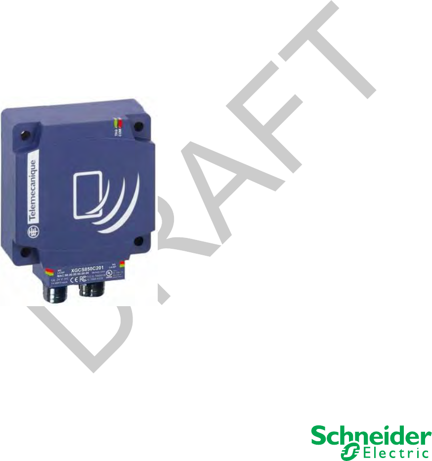
The OsiSense XG Smart Antenna is used to send information from the tag to the PLC and vice
versa, as described below:
1 PLC
2 Smart Antenna
3 Tag
Phases in the Process
The table shows the various exchange phases:
Phase Exchanges
PLC Smart Antenna Smart Antenna Tag
1Look for a tag in the dialog zone
2Positive response
3 Send a read/write command
4 Execution of the command (with checks)

DI[D-SE-0029834.1.7] General Information
EIO0000001601 Draft 2013/07/17 13
NOTE:
If phase 3 is carried out with no tag present, a detected error message is sent back to the PLC.
If a detected error occurs in phase 4, this phase is automatically restarted (up to 3 times). If a
detected error is still detected at the end of phase 4, a detected error report is sent back in phase
5.
5 Send back report
Phase Exchanges
PLC Smart Antenna Smart Antenna Tag
General Information DI[D-SE-0029835.1.3]
14 EIO0000001601 Draft 2013/07/17
Overview of the OsiSense XG Range
Overview of the OsiSense XG Range
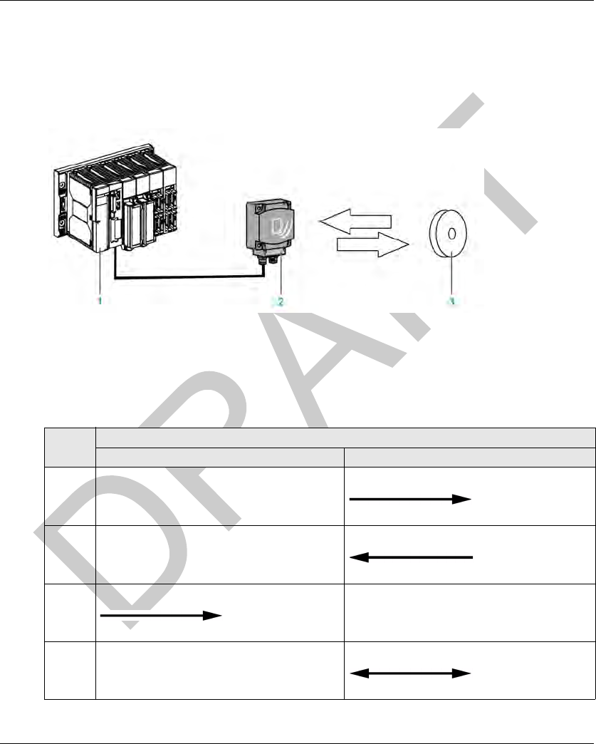
Introduction
The figure illustrates the OsiSense XG range.
DI[D-SE-0029981.1.6] General Information
EIO0000001601 Draft 2013/07/17 15
System Vi ew
System View
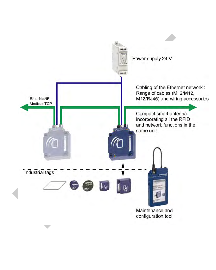
Description
OsiSense XG Smart Antenna can be used with a protocol compliant scanner as part of control
system architecture. The built-in unmanaged 2-port Ethernet switch of the Smart Antenna allows
you to use the network topology that meets your application needs. These topologies include the
following:
star
daisy-chain
ring (daisy-chain with loopback)
combination of star and daisy-chain
Star
Star topology allows you to connect additional network equipment. Performing maintenance on
one module—for example, by removing the network cable, or by cycling power to the module—
does not affect other modules.
1 Quantum PLC
2 Ethernet switch
3 Advantys STB Island
4 Magelis HMI device
5 OsiSense XG Smart Antenna
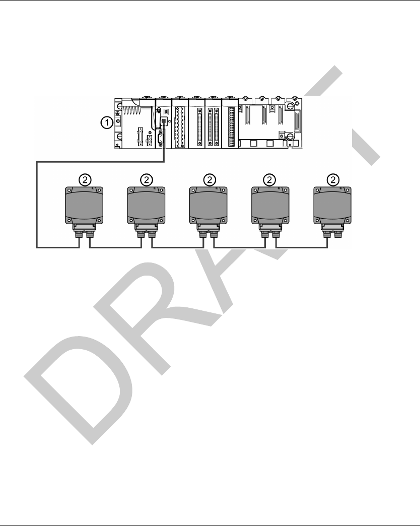
Daisy-Chain
You can create a daisy-chain topology by using the embedded switch ports to connect a series of
up to 32 OsiSense XG Smart Antennas.
NOTE:
General Information DI[D-SE-0029981.1.6]
16 EIO0000001601 Draft 2013/07/17
When considering the daisy chain topology, note that:
Performing maintenance on any module not physically located at the end of the daisy chain—
for example, by removing the network cable, or by cycling power to the module—affects any
modules located down the chain from the maintained module.
The embedded dual port Ethernet switch located in each module eliminates the need for
additional Ethernet switches.
1 M340 PLC
2 Ethernet switch
3 OsiSense XG Smart Antenna
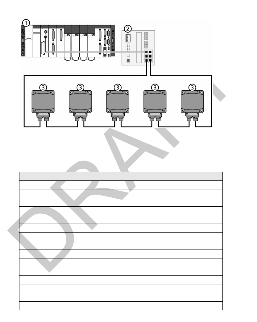
Ring
You can create a ring topology by using a switch with redundancy management protocol (for
example ConneXium TCSESM043F23F0).
You can connect a series of up to 32 OsiSense XG Smart Antennas.
NOTE:
When considering the ring topology, note that:
If a network segment becomes inoperable or is cut, all Smart Antennas remain operational.
DI[D-SE-0029981.1.6] General Information
EIO0000001601 Draft 2013/07/17 17
1 Premium PLC
2 Ethernet switch with loopback function
3 OsiSense XG Smart Antenna
The table shows the ConneXium switches with redundancy function compatible with Smart
Antennas:
Reference Description
TCSESB083F23F0 8 port basic managed switch 8TX
TCSESB083F2CU0 8 port basic managed switch 6TX – 2FX multi mode
TCSESB093F2CU0 9 port basic managed switch 6TX – 3FX multi mode
TCSESM043F1CS0 4 port managed switch 3TX – 1FX single mode
TCSESM043F1CU0 4 port managed switch 3TX – 1FX multi mode
TCSESM043F23F0 4 port managed switch 4TX
TCSESM043F2CS0 4 port managed switch 2TX – 2FX single mode
TCSESM043F2CU0 4 port managed switch 2TX – 2FX multi mode
TCSESM083F1CS0 8 port managed switch 7TX – 1FX single mode
TCSESM083F1CU0 8 port managed switch 7TX – 1FX multi mode
TCSESM083F23F0 8 port managed switch 8TX
TCSESM083F2CS0 8 port managed switch 6TX – 2FX single mode
TCSESM083F2CU0 8 port managed switch 6TX – 2FX multi mode
TCSESM103F23G0 10 port managed switch 8TX/2TX-GBIT
TCSESM103F2LG0 10 port managed switch 8TX/2SFP-GBIT

General Information DI[D-SE-0029981.1.6]
18 EIO0000001601 Draft 2013/07/17
TCSESM163F23F0 16 port managed switch 16TX
TCSESM163F2CU0 16 port managed switch 14TX – 2FX multi mode
TCSESM163F2CS0 16 port managed switch 14TX – 2FX single mode
TCSESM243F2CU0 24 port managed switch 22TX – 2FX multi mode
TCSESM083F23F1 8 port extended managed switch 8TX
TCSESM063F2CS1 8 port extended managed switch 6TX – 2FX single mode
TCSESM063F2CU1 8 port extended managed switch 6TX – 2FX multi mode
Reference Description

EIO0000001601 Draft 2013/07/17 19
DI[D-SE-0029847.1.1]
RFID OsiSens e® XG
Specific ations and Physical Descripti on
EIO0000001601 Draft 2013/07/17
Specific ations an d Physical Description
Chapter 2
Specifications and Physical De scription
Specifications and Physical Description
Aim of this Chapter
This chapter presents the specifications and the physical description of the OsiSense XG Smart
Antenna.
What Is in This Chapter?
This chapter contains the following topics:
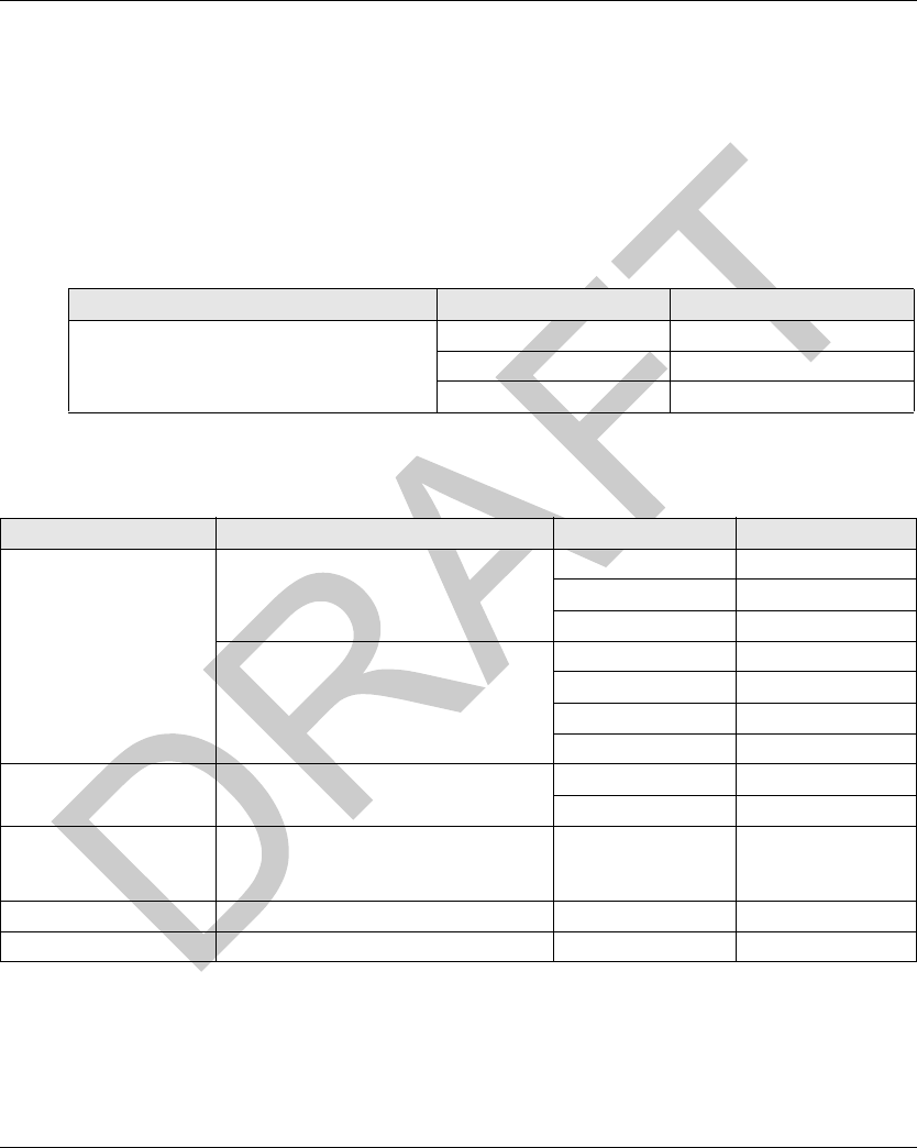
Topic Page
Smart Antenna Characteristics 20
Tags Characteristics 23
Description of the Smart Antenna 27
Connecting the OsiSense XG Smart Antenna 29
Wiring Accessories 30
Smart Antennas Wiring Example 32

Specifications and Physical Description DI[D-SE-0029851.1.7]
20 EIO0000001601 Draft 2013/07/17
Smart Antenna Characteristics
Smart Antenna Characteristics
Characteristics
The table gives the technical characteristics of the Smart Antenna:
WARNING TO USERS IN THE UNITED STATES AND CANADA
WARNING TO USERS IN THE UNITED STATES
Federal Communication Commission Interference Statement
47 CFR Section 15.105(b)
Characteristic Description
Temperature Operation –25...+70 °C (–13...+158
°
F)
Storage –40...+85 °C (–40...+185
°
F)
Degree of protection IP65 according to IEC60529
Vibration resistance
EN 60068.2.27
EN 60068.2.6
2 mm (0.078 in) from 5 to 29.5 Hz / 7 g (7 gn)from 29.5 to 150 Hz
30 g (30 gn) / 11 ms
Resistance to mechanical shocks IK02 according to EN 50102
Standards/Certifications UL 508, CE, EN 300330, EN 301489-01/03
Immunity to disturbances Immunity to electrostatic discharges, radiated electromagnetic fields, fast
transients, electrical surges, conducted and induced interference and power
frequency magnetic field according to IEC61000/EN 55022
Unit dimensions 80x93x40 mm (3.15x3.66x1.57 in)
RFID frequency 13.56 MHz
Type of associated tag Standardized ISO 15693 and ISO 14443 tags
Automatic detection of the tag type
Nominal range 20...100 mm (0.78...3.94 in) depending on associated tag
Power supply 24 Vdc PELV
Connection on M8 4 pins male socket
Power supply voltage limits 19.2...29 V including ripple
Power consumption < 150 mA
Communication Interface Ethernet dual port 10 BASE-T/100 BASE-TX
Connection 2 M12 D coded female sockets for chaining
Display - 2 dual color LED for RFID communication
- 4 dual color LED for Ethernet communication
Tightening torque for the mounting
screws
< 3.6 Nm (31.9 lbf-in)

DI[D-SE-0029851.1.7] Specifications and Physical Description
EIO0000001601 Draft 2013/07/17 21
This equipment has been tested and found to comply with the limits for a Class B digital device,
pursuant to Part 15 of the FCC Rules. These limits are designed to provide reasonable protection
against harmful interference in a residential installation. This equipment generates uses and can
radiate radio frequency energy and, if not installed and used in accordance with the instructions,
may cause harmful interference to radio communications. However, there is no guarantee that
interference will not occur in a particular installation.
If this equipment does cause harmful interference to radio or television reception, which can be
determined by turning the equipment off and on, the user is encouraged to try to correct the
interference by one of the following measures:
Reorient or relocate the receiving antenna.
Increase the separation between the equipment and receiver.
Connect the equipment into an outlet on a circuit different from that to which the receiver is
connected.
Consult the dealer or an experienced radio/TV technician for help.
This device Equipment name complies with Part 15 of the FCC Rules. Operation is subject to the
following two conditions:
1. This device may not cause harmful interference.
2. This device must accept any interference received, including interference that may cause
undesired operation.
NO UNAUTHORIZED MODIFICATIONS
47 CFR Section 15.21
CAUTION: This equipment may not be modified, altered, or changed in any way without signed
written permission from SCHNEIDER ELECTRIC. Unauthorized modification may void the
equipment authorization from the FCC and will void the SCHNEIDER ELECTRIC warranty.
WARNING TO USERS IN THE CANADA / ATTENTION POUR LES UTILISATEURS AU
CANADA
This device complies with Industry Canada licence-exempt RSS standard(s). Operation is subject
to the following two conditions:
1. this device may not cause interference, and
2. this device must accept any interference received, including interference that may cause
undesired operation of the device.
Under Industry Canada regulations, this radio transmitter may only operate using an antenna of a
type and maximum (or lesser) gain approved for the transmitter by Industry Canada. To reduce
potential radio interference to other users, the antenna type and its gain should be so chosen that
the equivalent isotropically radiated power (e.i.r.p.) is not more than that necessary for successful
communication.
Le présent appareil est conforme aux CNR d’Industrie Canada applicables aux appareils radio
exempts de licence. L’exploitation est autorisée aux deux conditions suivantes :
1. il ne doit pas produire de brouillage, et
2. l’utilisateur du dispositif doit être prêt a accepter tout brouillage radioélectrique reçu, même si
ce brouillage est susceptible de compromettre le fonctionnement du dispositif.

Specifications and Physical Description DI[D-SE-0029851.1.7]
22 EIO0000001601 Draft 2013/07/17
Conformément à la réglementation d’Industrie Canada, le présent émetteur radio peut fonctionner
avec une antenne d’un type et d’un gain maximal (ou inférieur) approuvé pour l’émetteur par
Industrie Canada. Dans le but de réduire les risques de brouillage radioélectrique à l’ intention
d’autres utilisateurs, il faut choisir le type d’antenne et son gain de sorte que la puissance isotrope
rayonnée équivalente (p.i.r.e.) ne dépasse pas l’intensité nécessaire à l’établissement d’une
communication satisfaisante.
References:
Reference XGCS850C201
FCC ID Y7HXGCS85
IC info 7002C-XGCS85

DI[D-SE-0029867.1.12] Specifications and Physical Description
EIO0000001601 Draft 2013/07/17 23
Tags Characteristics
Tags Characteristics
Tag Characteristics
The table gives the technical characteristics of the tags with EEPROM memory:
Type of Tag XGHB44534
5
XGHB44434
5
XGHB32034
5
XGHB22134
6
XGHB21134
5
XGHB90E340
Operation
temperature
–25...+70 °C
(–13...+158
°
F)
–25...+55 °C
(–13...+131
°
F)
Storage
temperature
–40...+85 °C
(–40...+185
°
F)
–40...+55 °C
(–40...+131
°
F)
Degree of protection IP68 IP65 IP68 IP65
Standards
supported
ISO 14443 ISO 15693
Vibration resistance
EN 60068.2.27
EN 60068.2.6
2 mm (0.078 in) from 5 to 29.5 Hz / 7 g (7 gn)from 29.5 to 150 Hz
30 g (30 gn) / 11 ms
Resistance to
mechanical shocks
IK02 according to EN 50102
Dimensions 40x40x15 mm
(1.57x1.57x0.59 in)
∅ 30x3 mm
(1.18x0.12 in)
26x26x13
mm
(1.02x1.02x0.
51 in)
∅ 18 mm
(0.70 in)
58x85.5x1 mm
(2.28x3.34x0.0
39 in)
Casing materials PBT PC PBT PVC
Mounting method Screw or clip Screw Screw or clip Threaded
hole
-
Tightening torque for
the mounting screws
< 1 Nm (8.85 lbf-in) --
Memory capacity
(bytes)
13 632 3 408 112 256 256 256
Type of memory EEPROM
Type of operation Read/Write
Nominal range
(Read/Write)
40 mm
(1.57 in)
48 mm
(1.89 in)
65 mm
(2.56 in)
55 mm
(2.16 in)
20 mm
(0.78 in)
100 mm
(3.94 in)
Number of read
cycles
Unlimited
Number of write
cycles
100000 provided over the entire temperature range
Number of write
cycles at 30 °C
(86
°
F)
2.5 million typical cases

Specifications and Physical Description DI[D-SE-0029867.1.12]
24 EIO0000001601 Draft 2013/07/17
The table gives the technical characteristics of the tags with FeRAM memory:
Tag Memory Zone
These tags are addressed according to the table below and are accessible in Read/Write mode.
Read/Write time Read/Write time (see page 25)
Retention period 10 years
Type of Tag XGHB44534
5
XGHB44434
5
XGHB32034
5
XGHB22134
6
XGHB21134
5
XGHB90E340
Type of Tag XGHB320246 XGH440245 XGH440845 XGHB443245
Temperature Operation –25...+70 °C
(–13...+158
°
F)
Storage –40...+85 °C
(–40...+185
°
F)
Degree of protection IP65 IP68
Standards supported ISO 15693 ISO 14443
Vibration resistance
EN 60068.2.27
EN 60068.2.6
2 mm (0.078 in) from 5 to 29.5 Hz / 7 g (7 gn)from 29.5 to 150 Hz
30 g (30 gn) / 11 ms
Resistance to mechanical
shocks
IK02 according to EN 50102
Dimensions ∅ 30x3 mm
(1.18x0.12 in)
40x40x15 mm (1.57x1.57x0.59 in)
Casing materials PC PBT
Mounting method Screw Screw or clip
Tightening torque for the
mounting screws
< 1 Nm (8.85 lbf-in)
Memory capacity (bytes) 2 000 2 000 8 192 32 768
Type of memory FeRAM
Type of operation Read/Write
Nominal range (Read/Write) 65 mm (2.56 in) 39 mm (1.53 in)
Number of read cycles Unlimited
Number of write cycles 1010 provided over the entire temperature range
Read/Write time Read/Write time (see page 25)
Retention period 10 years

DI[D-SE-0029867.1.12] Specifications and Physical Description
EIO0000001601 Draft 2013/07/17 25
The Smart Antenna can read any tag in the XGHB range (automatic detection of the tag type).
NOTE: If an address requested is out of the range address of the tag, a detected error code is
generated.
NOTE: Once the Smart Antenna has auto-detected the XGHB445345 tag, it will no longer
recognize the XGHB444345 tag.
Read/Write Time and Tags Maximum Speed
The table shows the calculation of read/write time in static, and the tags maximum speed in
dynamic:
Tag Reference Memory Size Range Addresses
Dec Hex
XGHB320345 112 bytes 0...55 0...37
XGHB90E340 256 bytes 0...127 0...7F
XGHB211345 256 bytes 0...127 0...7F
XGHB221346 256 bytes 0...127 0...7F
XGHB440245 2000 bytes 0...999 0...3E7
XGHB320246 2000 bytes 0...999 0...3E7
XGHB444345 3408 bytes 0...1703 0...6A7
XGHB440845 8192 bytes 0...4095 0...FFF
XGHB445345 13632 bytes 0...6815 0...1A9F
XGHB443245 32768 bytes 0...16383 0...3FFF
NOTICE
UNINTENDED OPERATION
Do not use in the same tag application XGHB445345 and XGHB444345.
Failure to follow these instructions can result in equipment damage.
Tag Reference Static Dynamic
Access Time Calculation Tag Maximum Speed (m/s)
Read Time (ms) Write Time (ms) Read a Serial
Number
Read a Word* Read or Write
10 Words*
XGHB320345 12 + 0.825 x N 12 + 5.6 x N 5.8 2.7 0.9
XGHB90E340 12 + 0.825 x N 20 + 11.8 x N 7.1 4.0 0.8
XGHB211345 12 + 0.825 x N 19 + 4.1 x N 3.2 1.1 0.6

Specifications and Physical Description DI[D-SE-0029867.1.12]
26 EIO0000001601 Draft 2013/07/17
N: Number of 16-bit words
*: with use of the “Auto read/write” function
XGHB221346 12 + 0.825 x N 20 + 11.8 x N 4.2 2.6 0.5
XGHB440245 7 + 2 x N 7 + 2.4 x N 3.5 2.5 1
XGHB320246 7 + 2 x N 7 + 2.4 x N 3.5 2.5 1
XGHB444345 9.25 + 0.375 x N 13 + 0.8 x N 4.8 2.7 1.8
XGHB440845 6 + 0.25 x N 6 + 0.25 x N 3.8 3.0 2.6
XGHB445345 16.25 + 0.375 x N 20 + 0.8 x N 4.2 2.0 1.5
XGHB443245 6 + 0.25 x N 6 + 0.25 x N 3.8 3.0 2.6
Tag Reference Static Dynamic
Access Time Calculation Tag Maximum Speed (m/s)
Read Time (ms) Write Time (ms) Read a Serial
Number
Read a Word* Read or Write
10 Words*
DI[D-SE-0029856.1.3] Specifications and Physical Description
EIO0000001601 Draft 2013/07/17 27
Description of the Smart Ante nna
Description of the Smart Antenna
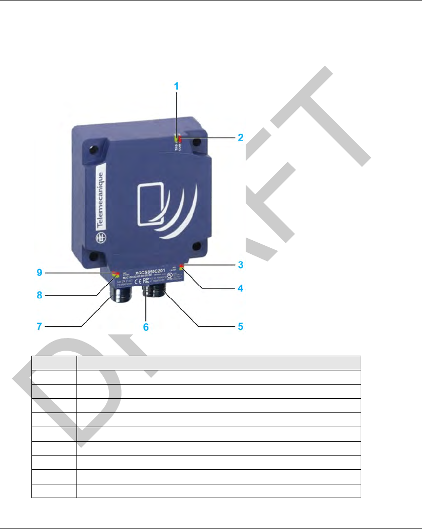
Presentation of the Smart Antenna
The figure presents the Smart Antenna:
No. Description
1 TAG: Tag LED
2 COM: Communication LED
3 NS: Network Status LED
4 LK/SP: Ethernet communication port No. 1 LED
5 M12 socket, Ethernet port No. 1
6 M8 socket, 24 Vdc power supply
7 M12 socket, Ethernet port No. 2
8 LK/SP: Ethernet communication port No. 2 LED
9 MS : Ethernet Module Status LED
Specifications and Physical Description DI[D-SE-0029856.1.3]
28 EIO0000001601 Draft 2013/07/17
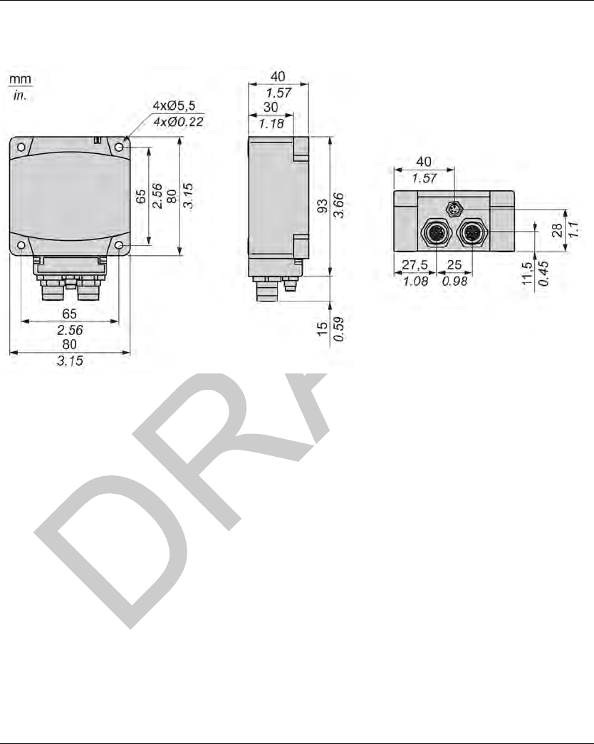
Dimensions
The figure shows the dimensions of the Smart Antenna:

DI[D-SE-0029857.1.5] Specifications and Physical Description
EIO0000001601 Draft 2013/07/17 29
Connecting the OsiSense X G Smart Antenna
Connecting the OsiSense XG Smart Antenna
Introduction
The Smart Antenna is equipped with:
a male M8 connector for the power supply,
2 female M12 D-coded connectors for Ethernet communication.
Power Supply Wiring
The table describes the M8 connector pinout:
NOTE: Use a PELV power supply and fuse protection (1 A). The power supply used must be class
II according to VDE 0106 (for example: Phaseo ABL 7/8 range of Schneider Electric). The 0 V must
be connected to the ground to increase EMC strength.
Communication Wiring
The table describes the M12 connectors pinout and the correspondence with the RJ45 connector
of communication cables (seepage30):
M8 Connector Pin No. Signal XZCP0941L• Wire Color
1+24 V Brown
2 Not connected White
30V Blue
4 Not connected Black
M12 Connector M12 Pin Signal Description RJ45 Pin RJ45 Connector
1 TD+ Transmit Data + 1
2 RD+ Received Data + 2
3 TD– Transmit Data – 3
4 RD– Received Data – 6
- - Not connected 4
- - Not connected 6
- - Not connected 7
- - Not connected 8
Specifications and Physical Description DI[D-SE-0030135.1.6]
30 EIO0000001601 Draft 2013/07/17
Wiring Ac cessories
Wiring Accessories
Introduction
The range of accessories is composed of power supply cables, communication cables, and
Ethernet connection accessories.
Power Supply Cables
The table shows the range of power supply cables:
Communication Cables
The table shows the range of communication cables:
* The maximum length of Ethernet connecting cables made up in this way is 80 m (262.5 ft).
Description Length Reference
Pre-wired M8 connector 2 m (6.56 ft) XZCP0941L2
5m (16.4 ft) XZCP0941L5
10 m (32.8 ft) XZCP0941L10
Description End Fittings Length Reference
Copper connecting
cables, straight
1 x IP67 M12 4-pin connector and 1 x
RJ45 connector
1m (3.28 ft) XGSZ12E4501
3m (9.84 ft) XGSZ12E4503
10 m (32.8 ft) XGSZ12E4510
2 x IP67 M12 4-pin connectors 1 m (3.28 ft) XGSZ12E1201
3m (9.84 ft) XGSZ12E1203
10 m (32.8 ft) XGSZ12E1210
25 m (82 ft) XGSZ12E1225
Copper connecting
cables, elbowed
1 x IP67 M12 4-pin elbowed connector
and 1 x RJ45 connector
3m (9.84 ft) XGSZ22E4503
10 m (32.8 ft) XGSZ22E4510
Ethernet copper cable (2 x
24 AWG shielded twisted
pairs)
Connectors to install 300 m (984.2 ft)* TCSECN300R2
RJ45 connector Conforms to EIA/TIA-568-D - TCSEK3MDS
M12 connector Conforms to IEC 60176-2-101 - TCSEK1MDRS

DI[D-SE-0030135.1.6] Specifications and Physical Description
EIO0000001601 Draft 2013/07/17 31
Ethernet Connection Accessories
The table shows the range of Ethernet connection accessories:
Description Reference
ConneXium M12 Ethernet switch IP67 TCSESU051F0
ConneXium Ethernet switch with loopback function TCSESB••••••••
TCSESM••••••••
M12 female / RJ45 adaptor TCSESAAF11F13F00
M12 connector cap for Smart Antenna ASI67FACC1

Specifications and Physical Description DI[D-SE-0029858.1.6]
32 EIO0000001601 Draft 2013/07/17
Smart Antennas Wiring Exampl e
Smart Antennas Wiring Example
Connection Diagram
Example of an Ethernet TCP/IP network setup with Smart Antennas:
1 PLC
2 Ethernet switch
3 Smart Antenna
4 Ethernet cable XGSZ12E45••
5 Ethernet cable XGSZ12E12••
6 Power supply cable XZCP0941L•
7 M12 connector cap ASI67FACC1 (2 caps are supplied with the Smart Antenna)
The maximum length of each segment is 100 m (328 ft).
In this example, the maximum bus length is 400 m (984.2 ft):
100 m (328 ft) between the PLC and the Ethernet switch,
3 x 100 m (328 ft) between each Smart Antennas.
NOTE: It is possible to chain up to 32 Smart Antennas.

EIO0000001601 Draft 2013/07/17 33
DI[D-SE-0029862.1.2]
RFID OsiSens e® XG
Installi ng the Sys tem
EIO0000001601 Draft 2013/07/17
Installi ng the Sys tem
Chapter 3
Installing the System
Installing the System
Aim of this Chapter
This chapter describes the procedure for installing the OsiSense XG Smart Antenna.
What Is in This Chapter?
This chapter contains the following topics:
Topic Page
Installation Precautions 34
IP Address Configuration 40
Installing the System DI[D-SE-0030154.1.9]
34 EIO0000001601 Draft 2013/07/17
Installat ion Precau tions
Installation Precautions
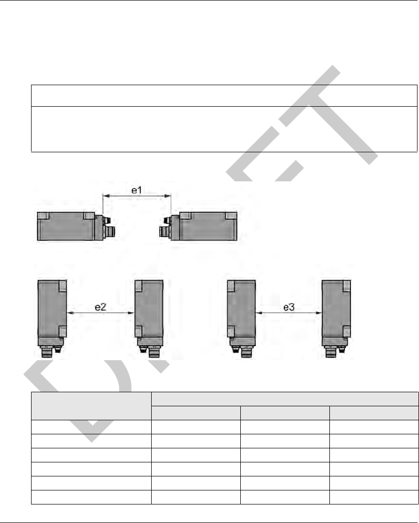
Distances Between Smart Antennas
When 2 Smart Antennas are too close, there is a risk of mutual disturbance.
Distances between 2 identical Smart Antennas depend on the tag used:
Minimum distances in mm (inches):
NOTICE
UNINTENDED OPERATION
Follow the installation precautions given in this chapter on distances between 2 Smart Antennas.
Failure to follow these instructions can result in equipment damage.
Tag Reference Minimum Distances in mm (inches)
e1 e2 e3
XGHB90E340 430 (16.92) 750 (29.52) 280 (11.02)
XGHB221346 280 (11.02) 530 (20.86) 260 (10.23)
XGHB320••• 310 (12.20) 540 (21.25) 240 (9.44)
XGHB211345 200 (7.87) 370 (14.56) 170 (6.69)
XGHB44•••• 310 (12.20) 400 (15.74) 160 (6.29)
XGHB123345 200 (7.87) 370 (14.56) 170 (6.69)
DI[D-SE-0030154.1.9] Installing the System
EIO0000001601 Draft 2013/07/17 35
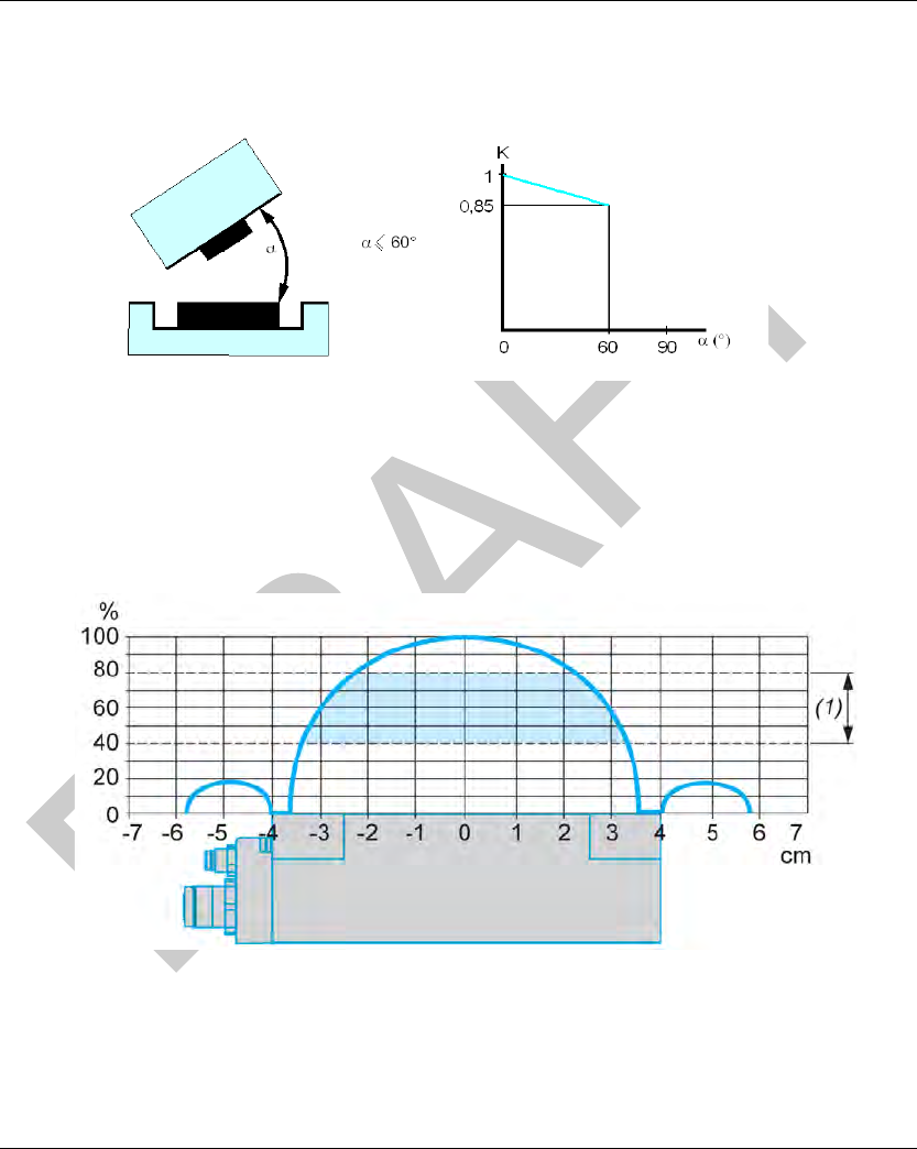
Angular Positioning
The angle between the Smart Antenna and the tag modifies the dialog distance according to the
graph below:
K = correction factor to be applied to the nominal range.
Reading distance = nominal range x K.
Sensing Zones
The dialog zones of the Smart Antenna are circular. There is no recommended direction for the
movement of the tag. The following diagram shows the dialog zones of the Smart Antenna:
(1) Movement zone consulted: between 0.4 and 0.8 of the nominal range.
NOTE: Nominal range (Pn)
The conventional range does not take the dispersions (manufacturing, temperature, voltage,
assembly in the metal) into account.
Installing the System DI[D-SE-0030154.1.9]
36 EIO0000001601 Draft 2013/07/17
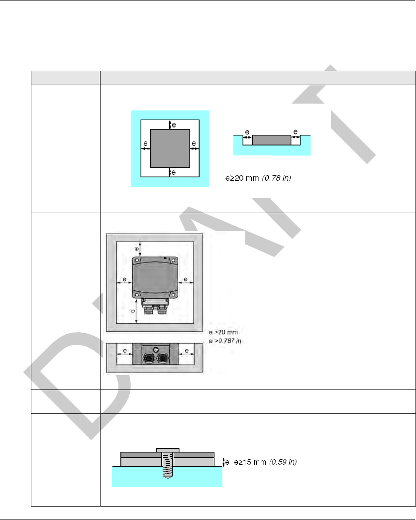
Mounting in the Metal
The presence of metal near the tags and the Smart Antenna affects the nominal range
(Reading/Writing distance).
The table shows the minimum assemblies allowed in a metal block:
References Description
XGCS4901201
XGCS8901201
XGHB221346
XGHB44•••
The product is positioned in a steel block:
XGCS850C201 The Smart Antenna is positioned in a steel block:
d depending on the connector size
XGHB90E340
XGHB211345
No metallic piece is less than 25 mm (0.98 in.) from the tag.
XGHB320246
XGHB320345
The tag is fixed with an M4 steel screw (tightening torque = 1 Nm (8.85 lbf-in)).
It is necessary to insert a non-metallic wedge between the tag and the metal tag:

DI[D-SE-0030154.1.9] Installing the System
EIO0000001601 Draft 2013/07/17 37
The table shows the effect on the nominal range when the Smart Antenna and the tag are
assembled in metal according to the most unfavorable cases shown above:
Distances Between Tags
NOTE: When 2 tags are too close to one another, this may trigger dialog errors.
Reference Memory
Size
(bytes)
Dimensions Reduced Sensing
Distance with
Presence of Metal
Nominal Sensing
Distance
XGHB90E340 256 Badge of 85x58x0.8 mm
(3.35x2.28x0.03 in.)
80 mm
(3.15 in.)
100 mm
(3.94 in.)
XGHB221346 256 26x26x13 mm
(1.02x1.02x0.51 in.)
33 mm
(1.29 in.)
55 mm
(2.16 in.)
XGHB320345 112 ∅ 30x3 mm
(1.18x0.12 in.)
56 mm
(2.20 in.)
65 mm
(2.56 in.)
XGHB320346 2000 ∅ 30x3 mm
(1.18x0.12 in.)
56 mm
(2.20 in.)
65 mm
(2.56 in.)
XGHB211345 256 ∅ 18x12 mm
(0.70x0.47 in.)
15 mm
(0.59 in.)
20 mm
(0.78 in.)
XGHB444345 3408 40x40x15 mm
(1.57x1.57x0.59 in.)
34 mm
(1.33 in.)
48 mm
(1.89 in.)
XGHB445345 13632 40x40x15 mm
(1.57x1.57x0.59 in.)
28 mm
(1.10 in.)
40 mm
(1.57 in.)
XGHB440245 2000 40x40x15 mm
(1.57x1.57x0.59 in.)
45 mm
(1.77 in.)
65 mm
(2.56 in.)
XGHB440845 8192 40x40x15 mm
(1.57x1.57x0.59 in.)
39 mm
(1.53 in.)
28 mm
(1.10 in.)
XGHB443245 32768 40x40x15 mm
(1.57x1.57x0.59 in.)
39 mm
(1.53 in.)
28 mm
(1.10 in.)
NOTICE
UNINTENDED OPERATION
Follow the installation precautions given in this chapter on distances between 2 tags.
Failure to follow these instructions can result in equipment damage.
Installing the System DI[D-SE-0030154.1.9]
38 EIO0000001601 Draft 2013/07/17
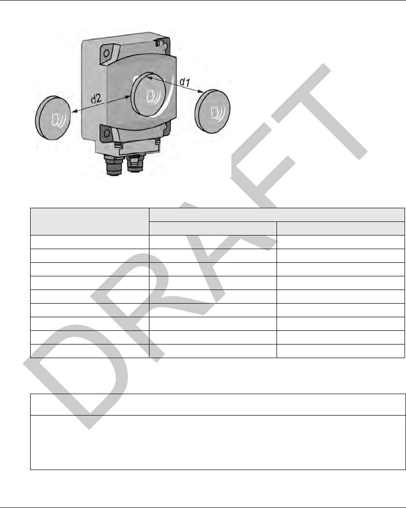
This figure illustrates the minimum distance between 2 identical tags:
Minimum distances between 2 identical tags according to their positioning:
Electromagnetic Disturbances
NOTE: Electromagnetic disturbances may block the dialog between the Smart Antenna and a tag.
Tag Reference Minimum Distances in mm (inches)
d1 d2
XGHB90E340 140 (5.51) 110 (4.33)
XGHB221346 50 (1.96) 120 (4.72)
XGHB320345 60 (2.36) 190 (7.48)
XGHB320246 60 (2.36) 190 (7.48)
XGHB211345 20 (0.78) 120 (4.72)
XGHB444345 40 (1.57) 70 (2.75)
XGHB445345 10 (0.39) 60 (2.36)
XGHB440845 10 (0.39) 60 (2.36)
XGHB443245 10 (0.39) 60 (2.36)
NOTICE
UNINTENDED OPERATION
Do not install the Smart Antenna less than 300 mm (12 in) from a device generating
electromagnetic disturbances (electric motor, solenoid valve...).
Failure to follow these instructions can result in equipment damage.

DI[D-SE-0030154.1.9] Installing the System
EIO0000001601 Draft 2013/07/17 39
Installing the System DI[D-SE-0029861.1.9]
40 EIO0000001601 Draft 2013/07/17
IP Addres s Configuration
IP Address Configuration
Introduction
IP address: Every item of equipment connected to an Ethernet network must have a unique IP
address. This address makes it possible to refer to a specific unit.
Subnet mask: The subnet mask defines a range of IP addresses that can be accessed from an
item of equipment.
The table describes the standard IP subnet masks:
The table gives an example of accessible address ranges depending on the network class:
NOTE: xxx represents a possible value from 0 to 255.
Address Configuration
The factory default address is 192.168.0.10.
The configuration of the IP address is made by setting parameters in the web server embedded in
the Smart Antenna to:
manually set the IP address,
automatically get an IP address from the DHCP server.
Network Class Host Bits Subnet Mask
A 24 255.0.0.0
B 16 255.255.0.0
C 8 255.255.255.0
Network Class Addresses Accessible Addresses
Ranges
B IP: 192.168.0.1
Mask: 255.255.0.0
IP: 192.168.xxx.xxx
C IP: 192.168.0.1
Mask: 255.255.255.0
IP: 192.168.0.xxx
NOTICE
UNINTENDED EQUIPMENT DAMAGE
Do not use factory configured IP address for operation.
Assign a new IP address for operation.
Failure to follow these instructions can result in equipment damage.
DI[D-SE-0029861.1.9] Installing the System
EIO0000001601 Draft 2013/07/17 41
NOTE: Two or more Smart Antennas with identical IP address on the same network generate a
duplicate IP condition (Smart Antenna Diagnostic LEDs (seepage126)).
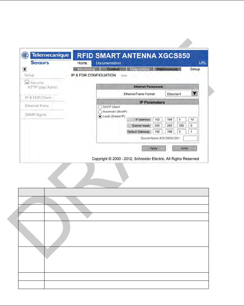
Configuring IP Address in the Web Server
The graphic shows the Smart Antenna web server IP & FDR CONFIGURATION page:
The table describes the steps to follow to configure the IP address in the IP & FDR
CONFIGURATION page:
Step Action
1 Access to the web server (see page 116).
2 Click the Setup tab on the Home page.
3 Click the IP & FDR CONFIGURATION link on the Setup page.
4 Select the type of IP addressing:
DHCP Client
Automatic (BootP)
Local (Stored IP)
5 If local addressing is selected, set the parameters of the Smart Antenna
IP address
Subnet mask
Default Gateway
6 Click Apply to validate the settings.
7 Cycle the Smart Antenna power off and on to apply the new settings.

Installing the System DI[D-SE-0029861.1.9]
42 EIO0000001601 Draft 2013/07/17
NOTE: The network configuration of the PC must be compatible with the IP address range of the
Smart Antenna.

EIO0000001601 Draft 2013/07/17 43
DI[D-SE-0029863.1.]
RFID OsiSens e® XG
Operatin g Principles
EIO0000001601 Draft 2013/07/17
Operating P rinciples
Chapter 4
Operating Principles
Operating Principles
Aim of this Chapter
This chapter describes the system operating principle based on memory zones.
What Is in This Chapter?
This chapter contains the following topics:
Topic Page
Read/Write Operating Mode 44
Memory Zones 48
Smart Antenna System Memory Zone 49
Smart Antenna Command/Instructions Memory Zone 51

Operating Principles DI[D-SE-0033453.1.1]
44 EIO0000001601 Draft 2013/07/17
Read/Write Operating Mode
Read/Write Operating Mode
Introduction
For read/write operations 2 operating modes are available:
Static read/write: applications where the tag is stopped in front of the Smart Antenna.
Dynamic read/write: applications where the tag does not stop in front of the Smart Antenna.
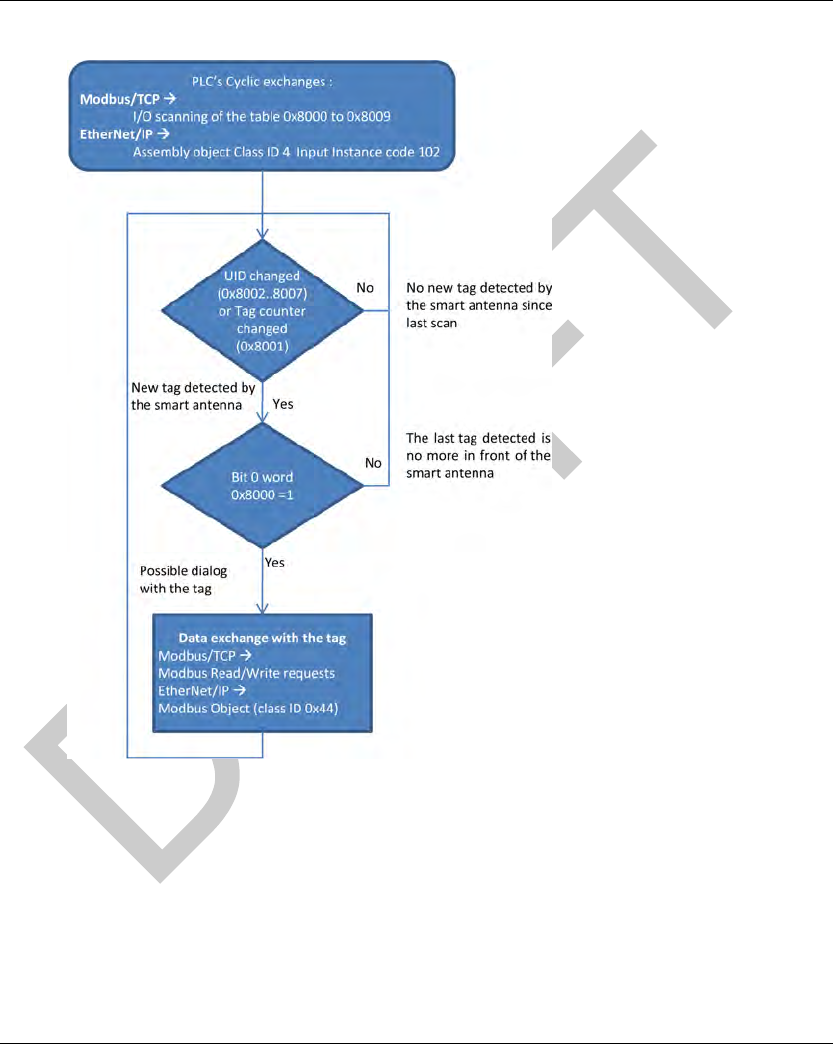
Static Read/Write
The controller must run cyclic scanning of the status of the Smart Antenna before sending read or
write requests addressed to the internal memory of the tag.
A table of words in the system memory area of the Smart Antenna is dedicated to this function:
Status word: a bit of this word is set to 1 when a tag is detected by the Smart Antenna.
Tag counter: this word is incremented each time a new tag is detected by the Smart Antenna.
UID: a group of 8 words where the UID of the last tag detected by the Smart Antenna is stored.
The combination of these information gives the exact status of the system:
Arrival of a tag in front of the Smart Antenna.
New tag or same tag as previous one.
Read/Write operations in the tag possible or not.
DI[D-SE-0033453.1.1] Operating Principles
EIO0000001601 Draft 2013/07/17 45
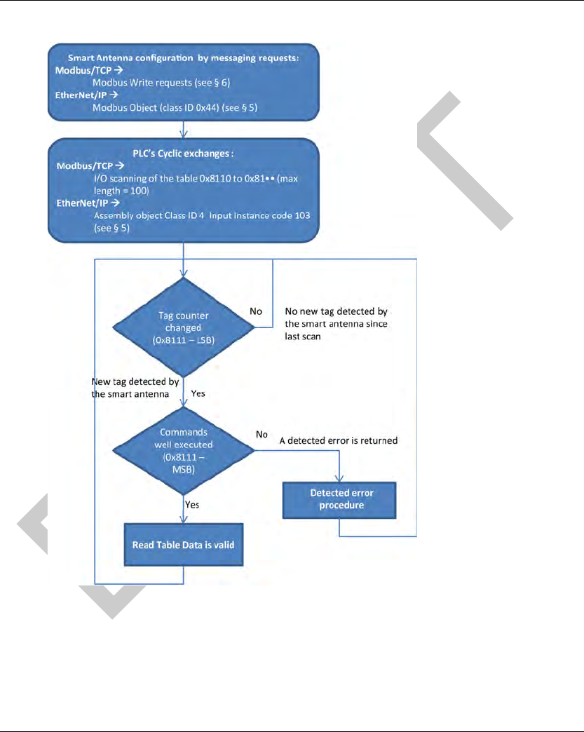
This diagram illustrates static read/write operations:
Dynamic Read/Write
The Smart Antenna can be configured to run automatically read/write commands each time a new
tag is detected. The results of the last commands are permanently accessible in the system
memory of the Smart Antenna (Reading Table (see page 54)). Synchronization between PLC
application program and tag presence is no more necessary.
First, the controller must send writing requests to the Smart Antenna to configure and activate the
automatic R/W commands (seepage51).

Operating Principles DI[D-SE-0033453.1.1]
46 EIO0000001601 Draft 2013/07/17
Then, the controller must run cyclic scanning of the reading table of the smart antenna:
First word: Status, a bit of this word is set to 1 when a tag is detected by the Smart Antenna.
Second word: tag counter and detected error code.
Third…X words: results of read commands.
The combination of these information gives the exact status of the system:
Arrival of a tag in front of the Smart Antenna.
New tag or same tag as previous one.
Data read from the last tag detected by the Smart Antenna.
All data will be overwritten by the arrival of the next tag.
DI[D-SE-0033453.1.1] Operating Principles
EIO0000001601 Draft 2013/07/17 47
This diagram illustrates dynamic read/write operations:
Operating Principles DI[D-SE-0029864.1.5]
48 EIO0000001601 Draft 2013/07/17
Memory Zones
Memory Zones
Presentation
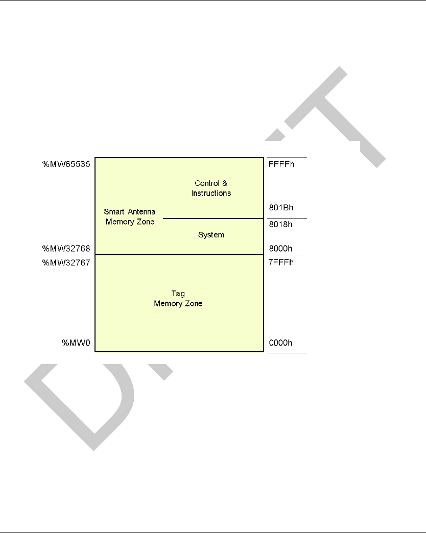
The addressing memory zone is divided into 2 zones:
The tag Memory Zone (see page 24)
The Smart Antenna memory zone:
System Zone (seepage49),
Command/instructions zone (seepage51).
Definition of the address zones of words used:

DI[D-SE-0029865.1.1] Operating Principles
EIO0000001601 Draft 2013/07/17 49
Smart Antenna System Memory Zone
Smart Antenna System Memory Zone
Description of the Zone
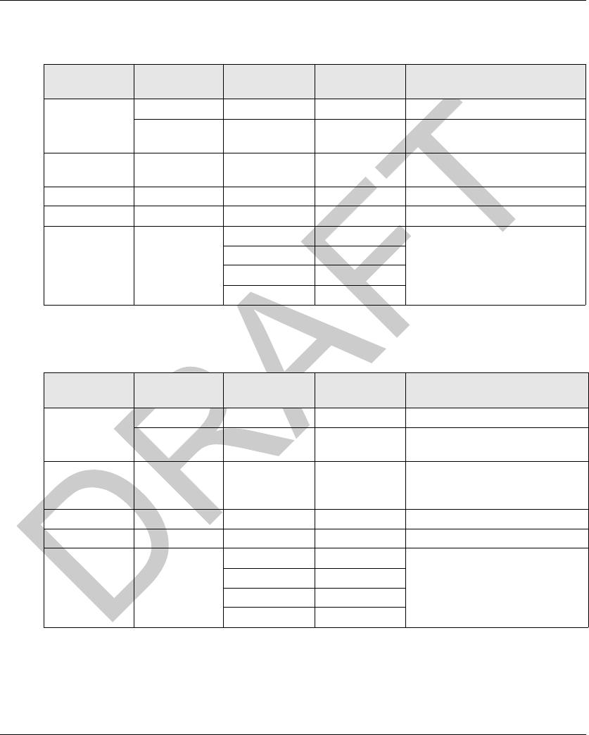
Composition of the system zone:
1 R = Read, W = Write
Modifications to values in this zone are taken into account by the Smart Antenna immediately.
Object 8000h
Status:
Object 8001h
Tag counter:
No. of Object Description Access 1Protected
8000h Tag family present / Tag system flags R No
8001h Tag counter R/W No
8002...8009h UID R No
8018h Smart Antenna address R/W Yes
MSB LSB
Tag family present
Indicates the tag family while it is
present. Reset when no longer present.
Tag system flag
Real-time updating.
Bit Bit
8 15693 0 (LSB) Tag present
9 Icode 1 Initial parameter-setting phase following
boot-up
A 14443A 2 Reserved
B 14443B 3 Reserved
C Inside 4 Reserved
D Reserved 5 Present configuration badge
E Reserved 6 Reserved
F (MSB) Reserved 7 Reserved
MSB LSB
Incremented each time there is a new tag. RAZ at each power switch-on. Possible written
access to predefine a value in the counter.

Operating Principles DI[D-SE-0029865.1.1]
50 EIO0000001601 Draft 2013/07/17
Objects 8002h...8009h
UID:
Each tag has a different single code (UID). This code is distributed in 16 bytes.
Object 8018h
Smart Antenna address:
Reading request:
Response to the reading request:
Writing request:
MSB LSB
Updated each time there is a new tag and valid if tag present.
MSB LSB
0 Smart Antenna address
Writing Request Result
MSB LSB
0...1E Smart Antenna address No action
1F Smart Antenna address The new Smart Antenna address is effective
immediately.

DI[D-SE-0029866.1.3] Operating Principles
EIO0000001601 Draft 2013/07/17 51
Smart Antenna Command/Instructions Memory Zone
Smart Antenna Command/Instructions Memory Zone
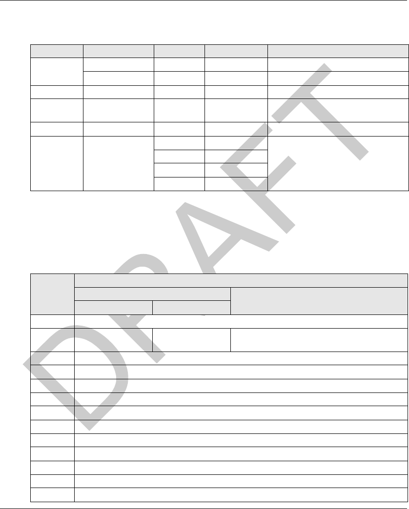
General Description
The zone can activate the commands or operating modes and consists of:
*: R = Read, W = Write
801Bh Object: Command
This object executes the following commands:
Reset:
reinitialization of the default factory adjustments
launching the initialization sequence
the Command/instructions memory zone is reset to zero
the sleep mode is deactivated
Init:
Smart Antenna reinitialization
launching the initialization sequence
the Command/instructions memory zone is reset to zero
the sleep mode is deactivated
Sleep Mode:
activation/deactivation of the Sleep Mode,
emission of the electromagnetic field of the Smart Antenna is activated only when receiving
a reading or writing request. This mode reduces the Smart Antenna consumption and frees
it from interferences when the Smart Antenna is close to another one.
Execution of the instructions block:
Address Table Description Access *Protected
801Bh Command Activates operations such as initialization,
automatic reading or writing, sleep mode, etc.
R/W No
801C...80AFh Reserved Reserved - -
80B0...80FF Instruction block Sets parameters by up to 10 instructions, which
will be executed sequentially.
R/W No
8100...810Fh Reserved Reserved - -
8110...817Fh Reading table Stores the results of the tag-reading operations
and monitors the execution of the instructions.
RNo
8190...81E6h Writing table Stores the data which are to be written in the
tags.
R/W No
81E7...FFFFh Reserved Reserved - -

Operating Principles DI[D-SE-0029866.1.3]
52 EIO0000001601 Draft 2013/07/17
defines the occurrence of executing the instructions block in the Smart Antenna
unit execution command: the instruction block is executed once after detecting the first tag
automatic execution command: the instruction block is executed at each tag detection up to
the next reset or when the Smart Antenna is switched off
NOTE: To be able to use the execution commands of the instructions block, the "Sleep" mode must
be deactivated. Since this mode cannot detect the presence of a tag in the dialog zone.
NOTE: After restarting the Smart Antenna, the 801Bh object automatically retrieves its default
value.
80B0...80FFh Object: Instruction Block
The instructions block predefines up to 10 instructions. The instructions are executed (in the
ascending order) when a tag is detected by the Smart Antenna.
Each instruction consists of 8 16-bit words which define the parameters associated with it. The
number of words used to set the parameters of different instructions varies. The words that are not
used must be defined at 0000h.
The first word of each instruction is divided into 2 parts:
The high-weight byte defines the type of instruction to be executed.
The low-weight byte defines the number of words processed by the instruction.
Data entry or instructions output is contained in the 2 tables:
a writing table containing the data to be written in a writing instruction
a reading table containing:
diagnostic information associated with the execution of the instructions block
data read in a reading instruction
Command Activation Deactivating
the
Command
Comment
Reset 4040h - After executing the command, the 801Bh object
automatically retrieves its default value.
Init 2020h -
Sleep Mode 1010h 1000h After restarting the Smart Antenna, the Sleep Mode is
deactivated.
Execution of
the instructions
block
0101h 0100h Single execution when a tag is present in front of the Smart
Antenna.
0202h 0200h Execution performed each time a new tag is present in front
of the Smart Antenna.
DI[D-SE-0029866.1.3] Operating Principles
EIO0000001601 Draft 2013/07/17 53
Reading Instruction (C1)
Instruction structure:
Writing Instruction (C0)
Instruction structure:
Word Instruction
Field
Type Value Comment
1st (MSB) Instruction code Byte C1h C1: Copy In
Number of
words
Byte 01...40h Number of words to be read
2nd (LSB) Address Word 0000...FFFFh Address of the first word to be read
from the Smart Antenna or tag
Reserved Word 0000h -
Reserved Word 0000h -
Unused Word 0000h System words to be defined at 0
Word 0000h
Word 0000h
Word 0000h
Word Instruction
Field
Type Value Comment
1st (MSB) Instruction code Byte C0h C0: Copy Out
Number of
words
Byte 01...40h Number of words to be written
2nd (LSB) Address Word 0000...FFFFh Destination address of the first
word to be written from the Smart
Antenna or tag
Reserved Word 0000h -
Reserved Word 0000h -
Unused Word 0000h System words to be defined at 0
Word 0000h
Word 0000h
Word 0000h
Operating Principles DI[D-SE-0029866.1.3]
54 EIO0000001601 Draft 2013/07/17
Copying instruction(CD)
Instruction structure:
8110...8174h Object: Reading Table
The reading table stores the consecutive result in a reading instruction (C1) as well as review the
execution review of the instructions block (2 words). Reading this review monitors progress of the
instructions sequence.
Structure of the reading table:
Word Instruction Field Type Value Comment
1st (MSB) Instruction code Byte CDh C0: Copy Data
Number of words Byte 01...FFh Number of words to be written
2nd (LSB) Data Word 0000...FFFFh Value to be copied
3rd Address Word 0000...7FFFh First memory zone address to be
written
4th Iteration Word 0001...1FFFh Number of iterations to be executed
Unused Word 0000h System words to be defined at 0
Word 0000h
Word 0000h
Word 0000h
Address Description
MSB LSB
PF Quartet Pf Quartet
8110h Smart Antenna status (image of the 8000h word), see Object 8000h (see page 49)
8111h Instruction no. Detected error code Tag counter (image of the 8001h word), see
Object 8001h (see page 49)
8112h Data read as 1, 1st reading instruction
8113h Data read as 2, 1st reading instruction
... ...
... Data read as N, 1st reading instruction
... Data read as 1, 2nd reading instruction
... Data read as 2, 2nd reading instruction
... ...
... Data read as N, 2nd reading instruction
... Data read as 1, nth reading instruction
... Data read as 2, nth reading instruction
... ...

DI[D-SE-0029866.1.3] Operating Principles
EIO0000001601 Draft 2013/07/17 55
NOTE: All reading instructions must not exceed the table capacity of 100 words.
Description of the 8111h object:
... Data read as N, nth reading instruction
... ...
8174h ...
Bit Signification Description
15...12 Instruction no. Number of the last instruction executed without detected error, such as
"Detected error in the 3rd block instruction, therefore, the instruction no. =
2h"
11...8 Detected error
codes
Modbus detected error codes:
1h: unknown function code or incorrect request format
2h: incorrect address, prohibited or protected zone or address not lying
in the tag memory zone
3h: incorrect data. Too much data in the frame or insufficient or quantity
= 0 or incompatible data
4h: execution fault detected (in reading, writing, or tag missing)
7...0 Tag counter Image of the 8001h tag counter
Address Description
MSB LSB
PF Quartet Pf Quartet
Operating Principles DI[D-SE-0029866.1.3]
56 EIO0000001601 Draft 2013/07/17
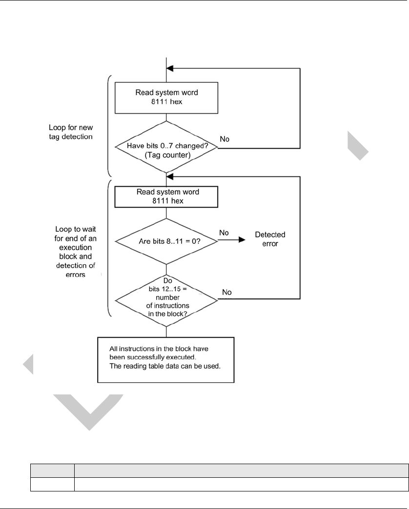
Monitoring the Execution of the Instructions Block
Reading the 8111h system word of the Smart Antenna controls the execution of the instructions
block:
8190...81E6h Object: Writing Table
The writing table stores the data to be written in a writing instruction.
Structure of the writing table:
Address Description
8190h Data to be written as 1, 1st written instruction

DI[D-SE-0029866.1.3] Operating Principles
EIO0000001601 Draft 2013/07/17 57
Application Example
In the following example, you will define an instruction block containing 3 instructions:
a reading instruction of 3 words at the 0001h address
a writing instruction of 2 words at the 0010h address
a reading instruction of 4 words at the 0020h address
Definition of the instructions block:
8191h Data to be written as 2, 1st written instruction
... ...
... Data to be written as N, 1st written instruction
... Data to be written as 1, 2nd written instruction
... Data to be written as 2, 2nd written instruction
... ...
... Data to be written as N, 2nd written instruction
... ...
... Data to be written as 1, nth written instruction
... Data to be written as 2, nth written instruction
... ...
... Data to be written as N, nth written instruction
... ...
81E6h ...
Address Description
Address Value Instruction no.
MSB LSB
80B0h C1h 03h 1
80B1h 0001h
80B2...80B7h 0000h
80B8h C0h 02h 2
80B9h 0010h
80BA...80BFh 0000h
80C0h C1h 04h 3
80C1h 0020h
80C2...80C7h 0000h
Operating Principles DI[D-SE-0029866.1.3]
58 EIO0000001601 Draft 2013/07/17
Definition of the writing table (data to be written in a writing instruction):
Setting the parameters to activate the commands for each tag movement:
Data received in the reading table after executing the instructions block:
Example of data received in the reading table after executing the instructions block containing
detected errors:
Address Value Instruction
Associated
8190h For example, FEFEh 2
8191h For example, 0A0Bh
Address Value Instruction Associated
801Bh 0202h Executing the instruction block at each new tag
Address Value Instruction Associated
MSB LSB
8110h Smart Antenna status -
8111h 30h 01h Composition:
30h (MSB) = 3 instructions executed without
detected error
01h (LSB) = 1st tag detected by the Smart
Antenna
8112h 0001h word content Result of instruction number 1 (reading 3 words)
8113h 0002h word content
8114h 0003h word content
8115h 0020h word content Result of instruction number 3 (reading 4 words)
8116h 0021h word content
8117h 0022h word content
8118h 0023h word content
Address Value Instruction Associated
MSB LSB
8110h Smart Antenna status -

DI[D-SE-0029866.1.3] Operating Principles
EIO0000001601 Draft 2013/07/17 59
Definition of an instruction block that can delete the first 50 words in each tag which is to be shown
in front of the Smart Antenna:
8111h 14h 01h Composition:
14h (MSB) = execution of the instructions block was
stopped due to a dialog detected error with the tag
in instruction number 2 (instruction number 1 was
executed correctly and instruction number 3 was not
executed)
01h (LSB) = 1st tag detected by the Smart Antenna
8112h 0001h word
content
Result of instruction number 1 (reading 3 words)
8113h 0002h word
content
8114h 0003h word
content
Address Value Instruction Associated
80B0h CD0Ah CD: Copy Data / 0Ah = 10 words deleted per iteration
80B1h 0000h Filling with the 000h value
Address 0000h First memory zone address to be written = 0000h
Iteration 0005h Number of iterations to be executed = 5
Address Value Instruction Associated
MSB LSB

Operating Principles DI[D-SE-0029866.1.3]
60 EIO0000001601 Draft 2013/07/17

EIO0000001601 Draft 2013/07/17 61
DI[D-SE-0029868.1.1]
RFID OsiSens e® XG
EtherNet /IP Commun ications Su pport
EIO0000001601 Draft 2013/07/17
EtherNet /IP Commun ications Su pport
Chapter 5
EtherNet/IP Com munications S upport
EtherNet/IP Communications Support
Introduction
This chapter describes how a Smart Antenna can be accessed from other devices on an
EtherNet/IP fieldbus network.
What Is in This Chapter?
This chapter contains the following sections:
Section Topic Page
5.1 Object Model 62
5.2 Unity Pro: EtherNet/IP Application Example 69
5.3 RSLogix: EtherNet/IP Application Example 82

EtherNet/IP Communications Support DI[D-SE-0029869.1.2]
62 EIO0000001601 Draft 2013/07/17
Object Model
Section 5.1
Object Model
Object Model
Introduction
This section describes the object model for the EtherNet/IP NIM. For general information about the
object model for a particular EtherNet/IP device, refer to ODVA specifications.
What Is in This Section?
This section contains the following topics:
Topic Page
About the Object Model 63
Assembly Object (Class ID 4) 65
Modbus Object (Class ID 0x44) 67

DI[D-SE-0029870.1.7] EtherNet/IP Communications Support
EIO0000001601 Draft 2013/07/17 63
About the Object Model
About the Object Model
Introduction
An EtherNet/IP node is modeled as a collection of objects. Each object provides an abstract
representation of a particular component within a product.
An object model defines the device’s:
I/O data format
configurable parameters
The above information is made available to other vendors through the EDS of the device.
This chapter describes the implemented objects of the Smart Antenna in terms of:
supported class attributes
supported class services
supported instance attributes
supported instance services
Further details can be found in Chapter 5 of [28] The CIP Networks Library Volume 2 EtherNet/IP
Adaptation of CIP.
Addressing Object Attributes
Objects: Objects provide services and implement behaviors.
Attributes: Attributes (object characteristics) for particular objects are addressed with integer
values that correspond to this hierarchy:
MAC ID (node ID)
class ID
instance ID
attribute ID
Supported Objects
This table lists the EtherNet/IP objects supported by the Smart Antenna:
Object Class Class ID Instance ID Messages Description
Identity Object 1 1 explicit This object returns the device type, vendor
ID, serial number, and so on.
Message Router
Object
2 1 explicit This object returns information about
message router implementation.
Assembly Object
(see page 65)
40x62, 0x66,
0x67 (98, 102,
103)
implicit I/O or
explicit
This object provides a collection of other
attributes of object.
Connection
Management
Object
6 0x01(1) explicit This object allows explicit messages to be
conducted.

EtherNet/IP Communications Support DI[D-SE-0029870.1.7]
64 EIO0000001601 Draft 2013/07/17
Port Object 0xF4 (244) 1 explicit This object returns information about the
Ethernet port.
TCP/IP Interface
Object
0xF5 (245) 1 explicit This object defines the number of
IP address configuration options for the
device.
Ethernet Link
Object
0xF6 (246) 1 explicit This object tracks configuration and
diagnostics information for the Ethernet
port.
Modbus Object
(see page 67)
0x44 (68) 1 explicit This object translates EtherNet/IP
messages into Modbus requests (code
function 0x3 and 0x10).
Object Class Class ID Instance ID Messages Description

DI[D-SE-0029871.1.7] EtherNet/IP Communications Support
EIO0000001601 Draft 2013/07/17 65
Assembly Obj ect (Class ID 4)
Assembly Object (Class ID 4)
Introduction
The assembly object groups different attributes (data) from a variety of application objects into a
single attribute that can be moved with a single message. This message provides the I/O data and
status of the Smart Antenna. Assembly objects can be used to bind input data or output data, as
defined from the network’s perspective. (That is, an input produces data on the network and an
output consumes data from the network.) For the Smart Antenna assembly object:
The class ID is 4.
The instance codes are 98 for the output instance, 102 and 103 for the input instances.
Class Attributes (Instance 0)
The assembly object supports these class attributes:
Class Services
The assembly object supports these class services:
Instance Codes
The Smart Antenna provides 3 instances of the assembly object class:
Attribute ID Name Access Description
0x01 Revision R This attribute returns the revision of the CIP object (0x02).
0x02 Max Instance R This attribute returns the maximum value of the instance number
(102).
0x03 Num Instances R This attribute returns the number of class instances. The value is
2.
0x06 Max. Class Attribute R This attribute returns the numeric value of the highest class
attribute (7).
0x07 Max. Instance
Attribute
R This attribute returns the numeric value of the highest instance
attribute (4).
Service Code Name Description
0x0E Get Attribute Single This service returns the value of the specified attribute.
Instance ID Access Size (Bytes) Description
98 R/W 2 Tag counter (Object 8001h (see page 49))
102 R 20 General status (Objects 8000...8009h, Smart Antenna System Memory
Zone (seepage49))
103 R 200 Read table of 100 words (8110...814Fh Object: Reading Table
(see page 54))

EtherNet/IP Communications Support DI[D-SE-0029871.1.7]
66 EIO0000001601 Draft 2013/07/17
NOTE:
For Rockwell PLC, one instance can be configured (98,102 or 103).
For Schneider Electric PLC under Unity environment, the 3 instances can be configured and
used in one application.
Instance Attributes
The assembly object supports these instance attributes:
Instance Services
The assembly object supports these instance services:
Attribute ID Name Access Description
1 Number of members R This attribute returns a word value of the number of members in
the instance.
2 Member list R This attribute is an array of structures in which each structure
represents one member and consists of:
member data size: a word containing the member data size (in
bits)
member path size: a word containing the byte size of the
subsequent EPATH:
0: unused space between members
0x09: actual members
member path: the EPATH representing the member (For
example, "20 04 24 65 30 28 01" is member 1 of instance 101.)
3 Instance data R/W This attribute returns instance data as an array of bytes. Access is:
read (only): input data assemblies
read/write: output data assemblies
4 Instance data size R This attribute returns a word representing the instance data size in
bytes. (The size depends on the particular I/O modules configured
on the bus.)
Service Code Name Description
0x0E Get Attribute Single This service returns the value of the specified attribute.
0x010 Set Attribute Single This service modifies an assembly object instance attribute value.
0x018 Get Member This service reads a member of an assembly object instance.
0x019 Set Member This service modifies a member of an assembly object instance.

DI[D-SE-0029872.1.4] EtherNet/IP Communications Support
EIO0000001601 Draft 2013/07/17 67
Modbus Object (Class ID 0x44)
Modbus Object (Class ID 0x44)
Introduction
The Modbus object is assigned a vendor-specific class ID of 68 (0x44). The Modbus object is an
application object that provides the read/write requests of the Smart Antenna memory zones. For
the Smart Antenna Modbus object:
The class code is 0x44 (68).
The single supported instance is 1.
Instance Services
The Modbus object supports these instance services:
Service Code 0x4E Description
The table describes the service parameters of the read holding registers request:
1The request parameter is little indian. The Modbus protocol is big endian. You may have to swap
bytes depending on the Modbus subsystem implementation.
The table describes the service parameters of the read holding registers response:
1The data is returned as 16-bit entities for each register. The actual data type of the values is
unknown.
2The response data is little indian. The Modbus protocol is big endian. You may have to swap bytes
depending on the Modbus subsystem implementation.
Service Code Name Description
0x4E Read holding registers This service sends a read request of the specified registers (123 words
maximum).
0x50 Write holding registers This service sends a write requests of the specified registers (123
words maximum).
Name Data Type Description Semantics of Values
Starting address UINT Offset in table to begin reading from1Zero based
Quantity of holding registers UINT Number of holding registers to read1 (Max
number = 123)
-
Name Data Type Description Semantics of Values
Holding register values Array of 16-bit word1Holding register values read2-

EtherNet/IP Communications Support DI[D-SE-0029872.1.4]
68 EIO0000001601 Draft 2013/07/17
Service Code 0x50 Description
The table describes the service parameters of the write holding registers request:
1The request parameter is little indian. The Modbus protocol is big endian. You may have to swap
bytes depending on the Modbus subsystem implementation.
The table describes the service parameters of the write holding registers response:
1The response parameters are little indian. The Modbus protocol is big endian. You may have to
swap bytes depending on the Modbus subsystem implementation.
Name Data Type Description Semantics of Values
Starting address UINT Offset in table to begin writing to1Zero based
Quantity of outputs UINT Number of output registers to write1 (123
maximum)
-
Output values Array of 16-bit word Output register values -
Name Data Type Description Semantics of Values
Starting address UINT Offset in table where writing began1Zero based
Quantity of outputs UINT Number of outputs forced1-

DI[D-SE-0030778.1.2] EtherNet/IP Communications Support
EIO0000001601 Draft 2013/07/17 69
Unity Pr o: EtherNe t/IP Appl ication E xample
Section 5.2
Unity Pro: EtherNet/IP Applica tion Example
Unity Pro: EtherNet/IP Application Example
Introduction
This example illustrates the configuration of a Smart Antenna on an EtherNet/IP network to
communicate with a Premium PLC on Unity Pro.
What Is in This Section?
This section contains the following topics:
Topic Page
Presentation 70
Creating a Project 71
Configuring the TSXETC101 EtherNet/IP Communication Module 72
Configuring the Ethernet Smart Antenna 75
Read Application Example 80

EtherNet/IP Communications Support DI[D-SE-0030779.1.3]
70 EIO0000001601 Draft 2013/07/17
Present ation
Presentation
Overview
This example illustrates the Smart Antenna on an Ethernet/IP network to communicate with a
Premium controller on Unity Pro.
It is a walkthrough for the configuration of the Smart Antenna with the following steps:
Create the required Premium platform on Unity Pro
Configure the Smart Antenna
1 command examples
NOTE: This example will not provide explanations on how to install the hardware, refer to the
document of the controller for this purpose.
Hardware Requirement
The hardware required to set up this example is the following:
A Premium controller TSXP576634M
A TSXETC101 Ethernet module
Smart Antenna
Software Requirement
The software required to set up this example is the following:
Unity Pro (version 6.0 or better)
DI[D-SE-0030780.1.2] EtherNet/IP Communications Support
EIO0000001601 Draft 2013/07/17 71
Creating a Proje ct
Creating a Project
Procedure
Use Unity Pro to create a new project:
Step Action
1 Launch Unity Pro.
2 In the Unity Pro main menu, select File → New....
The New Project window opens displaying a list of Schneider-Electric controller types.
3 In the New Project window, open the Premium sub-list and select the controller TSXP576634M.
4 Click OK.
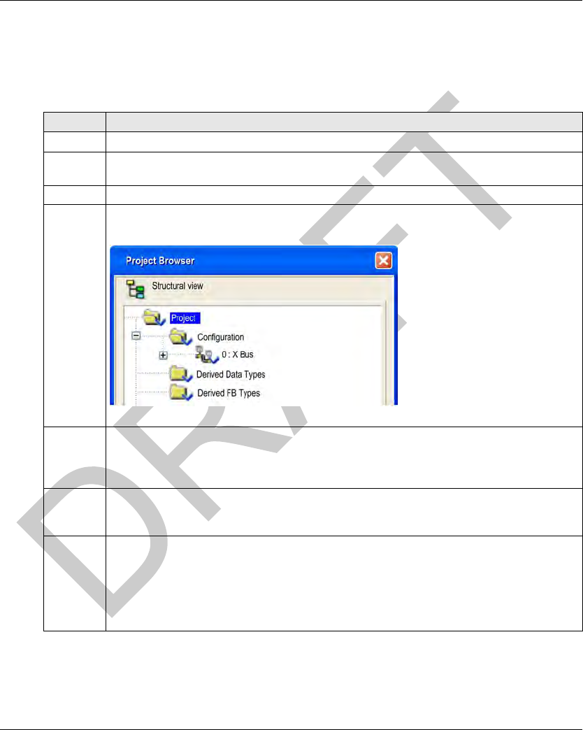
The Project Browser opens:
5In the Project Browser, double click Local Bus. Unity Pro displays:
the Hardware catalog, and
a Local Bus window with the selected CPU in the second position (slot 0) and a
TSXPSY2600M power supply in the first position
6In the Hardware catalog, use your mouse to drag a TSXETC101 EtherNet/IP communication
module from the Communication section to a position in the backplane. In this example, the
module is placed in the third position (slot 2).
7 To open the configuration window for the TSXETC101, do one of the following:
double click the left mouse button on the TSXETC101 module in the Local Bus window
above, or
click the right mouse button on the module, then select Open Module... in the popup menu
The module configuration window opens, where you can configure the properties for the
TSXETC101.
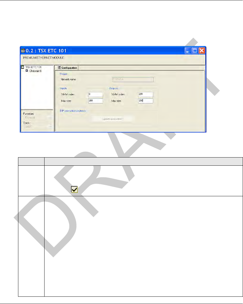
EtherNet/IP Communications Support DI[D-SE-0030781.1.4]
72 EIO0000001601 Draft 2013/07/17
Configuring t he TSXETC101 Et herNet/IP Com munication M odule
Configuring the TSXETC101 EtherNet/IP Communication Module
Setting Input and Output Memory Addresses and Naming the Module
The Configuration page looks like this:
In the Configuration page, perform the following steps to name the module, and to set addresses
and sizes for both inputs and outputs:
Step Action
1 In the Project section, type in a name for your network in the Network name input box - in this
example: P_ETC101
Note: After the module name is entered and the EtherNet/IP configuration is validated (by
clicking the button), the module name cannot be edited.
2 In the Input area and Output area, type in the size and starting position of both the inputs and
outputs. These values can be edited later. For this example, the following values are entered:
In the Input area:
In the %MW index field, type in a starting address for inputs—in this example: 0.
In the Max size field, type in the maximum number of 16-bit words dedicated to inputs—in
this example: 200.)
In the Output area:
In the %MW index field, type in a starting address for outputs—in this example: 201.
In the Max size field, type in the maximum number of 16-bit words dedicated to outputs—in
this example: 200.)
Notes:
The inputs and outputs can be located at any available address, and do not need to be
located in adjacent areas. It is important only that the space allocated to inputs and outputs
do not overlap
The specified %MW range for both inputs and outputs must be available in the CPU. For
more information, refer to the Unity Pro help file topic Processor Configuration Screen.
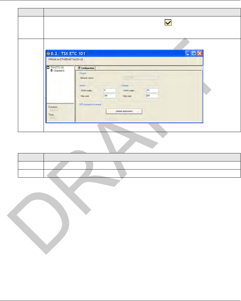
DI[D-SE-0030781.1.4] EtherNet/IP Communications Support
EIO0000001601 Draft 2013/07/17 73
Configuring the TSXETC101 Module Address
3In Unity Pro, select Edit → Validate (or click the Validate button) to:
save the EtherNet/IP network name—which becomes a non-editable, read-only value,
save the address and size settings for inputs and outputs.
3In the EIP connectivity network area, click the Update application button:
Step Action
Step Action
1 Select Tools → DTM Browser.
2 Double-click the P_ETC101 Ethernet module.
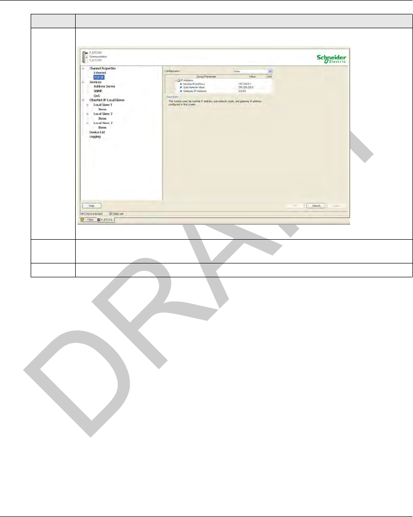
EtherNet/IP Communications Support DI[D-SE-0030781.1.4]
74 EIO0000001601 Draft 2013/07/17
3 In the Channel Properties entry click the TCP/IP subentry.
4 Double-click the Module IP Address and set the IP address to 192.168.0.3 (master address)
then press Enter.
5 Click Apply.
Step Action
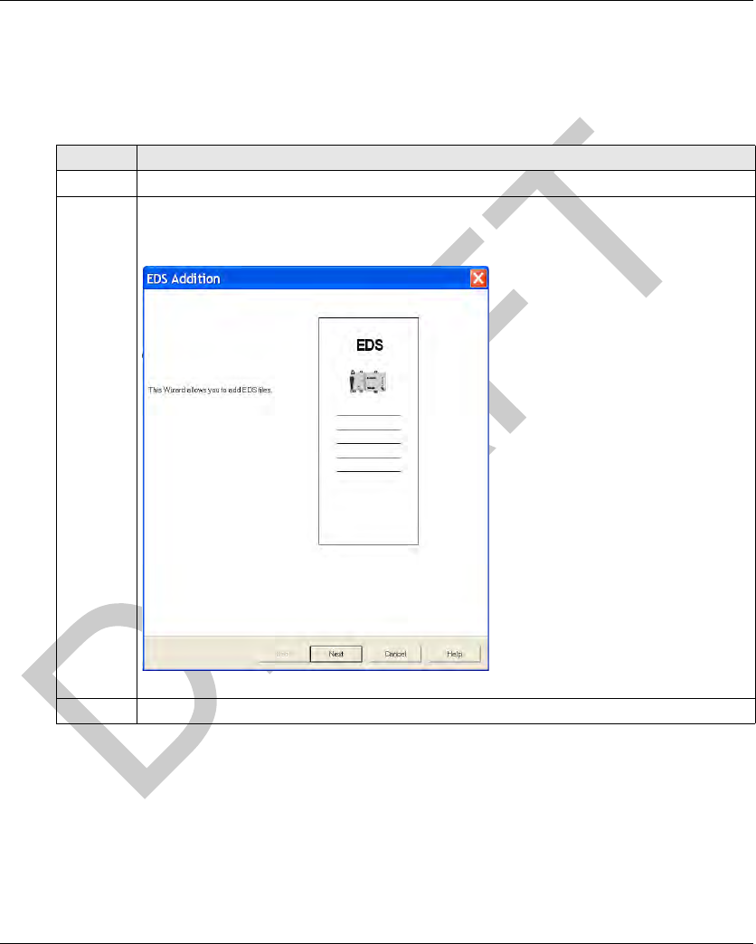
DI[D-SE-0030782.1.6] EtherNet/IP Communications Support
EIO0000001601 Draft 2013/07/17 75
Configuring t he Ethernet Sm art Antenna
Configuring the Ethernet Smart Antenna
Adding the Ethernet Smart Antenna EDS File
Follow this step if you have not added the Smart Antenna EDS file before:
Step Action
1 Click Tools → DTM Browser.
2In the DTM Browser, right-click the P_ETC101 Ethernet module.
Click Device menu → Additional functions → Add EDS to library.
The EDS Addition window appears:
3 Click Next button.
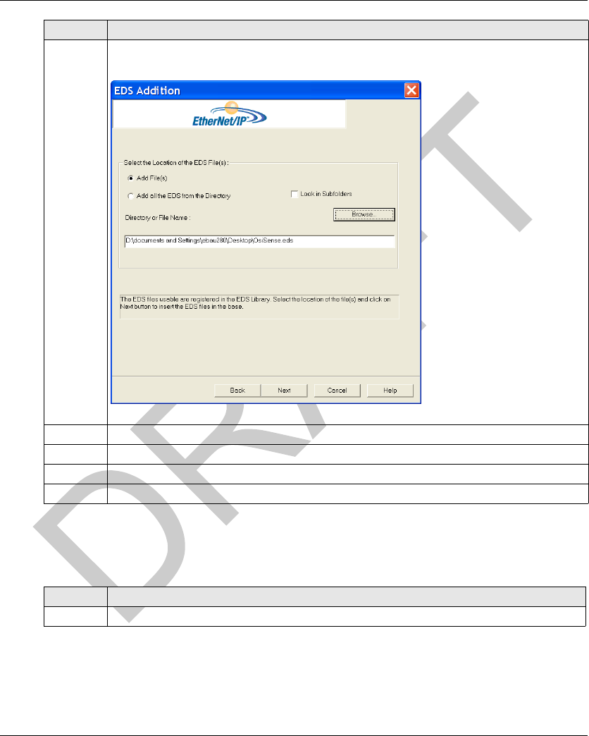
EtherNet/IP Communications Support DI[D-SE-0030782.1.6]
76 EIO0000001601 Draft 2013/07/17
Adding and Configuring the Ethernet Smart Antenna Devices
The Smart Antenna uses 2 connections to communicate on EtherNet/IP network, the Get Status
Connection and the Read Table Connection:
4 Click Browse and browse your computer folders to the location of the file OsiSense.eds select
the file and click Open.
5 Click Next.
6 Click Finish.
7 Click Tools → Hardware Catalog.
8 In the Hardware Catalog window, select the DTM Catalog tab and click Update.
Step Action
Step Action
1 In the DTM Browser window, right-click the P_ETC101 Ethernet module and click Add....
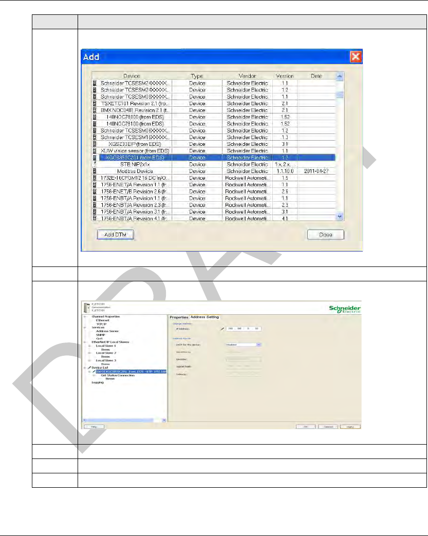
DI[D-SE-0030782.1.6] EtherNet/IP Communications Support
EIO0000001601 Draft 2013/07/17 77
2 Select the XGCS850C201 device in the list and click Add DTM:
3 Click Ok.
4In the Device List entry, click the Smart Antenna and select the Address Setting tab:
5 Click IP Address and set the IP address to 192.168.0.10 then press Enter.
6 Click Apply.
7 Repeat the steps 1 to 6 to add another Smart Antenna device with the same IP address.
Step Action
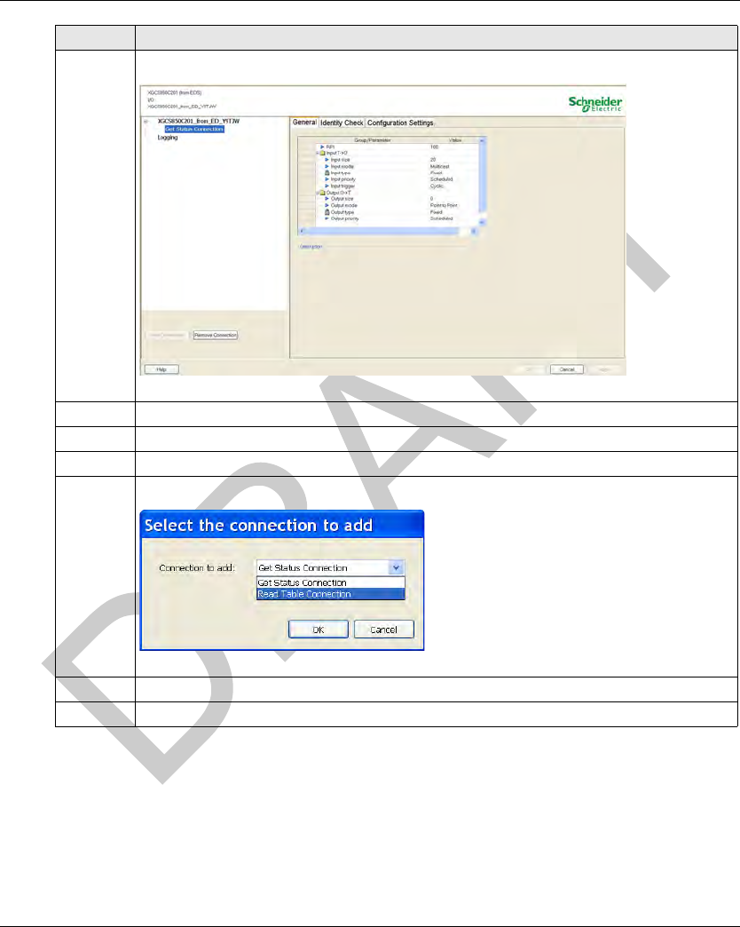
EtherNet/IP Communications Support DI[D-SE-0030782.1.6]
78 EIO0000001601 Draft 2013/07/17
8 In the DTM Browser window, double-click the new device. This window appears:
9 Click the Get Status Connection entry.
10 Click Remove Connection.
11 Click Add Connection.
12 Select Read Table Connection in the list and click Ok:
13 Click Apply.
14 Click Build → All Project.
Step Action
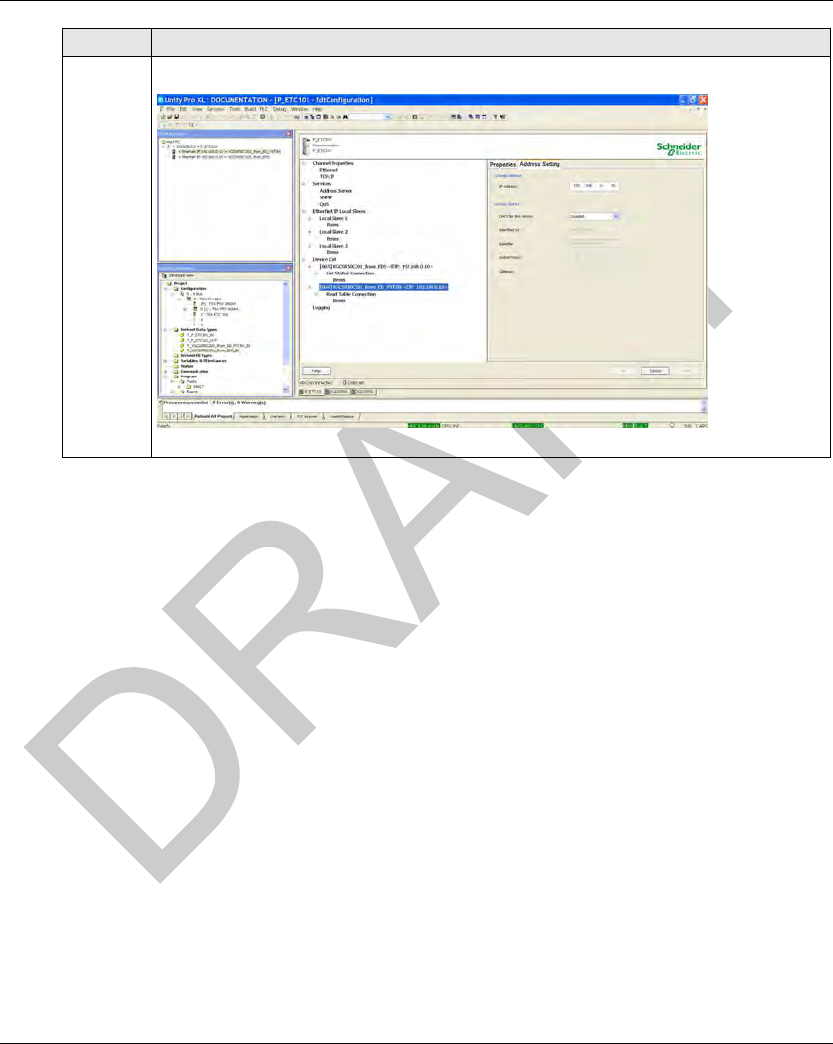
DI[D-SE-0030782.1.6] EtherNet/IP Communications Support
EIO0000001601 Draft 2013/07/17 79
15 The Smart Antenna is now configured to communicate on EtherNet/IP network.
Step Action
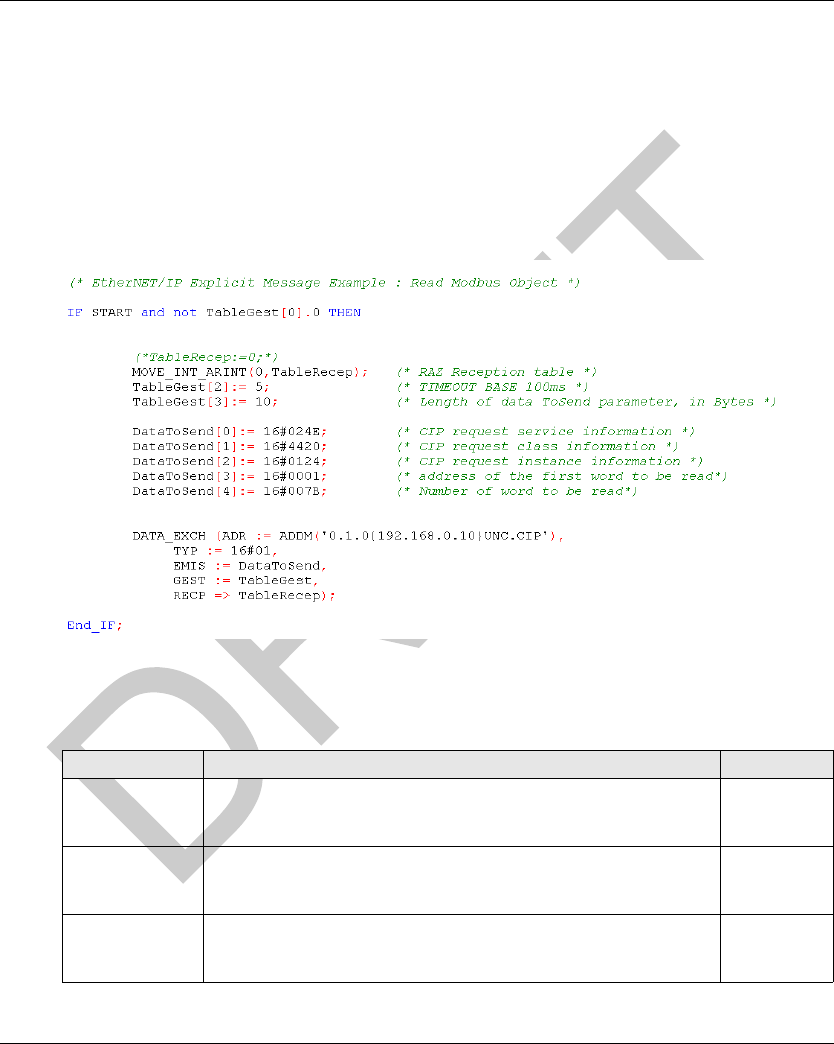
EtherNet/IP Communications Support DI[D-SE-0030784.1.6]
80 EIO0000001601 Draft 2013/07/17
Read Applicat ion Example
Read Application Example
Introduction
This example describes the implementation of the Modbus object (see page 67) for reading 123
words using the DATA_EXCH function. Refer to the Unity Pro online help for more information
about explicit message.
Example
CIP Request Description
The DataToSend variable identifies the type of explicit message and the CIP request:
Variable Description Value (hex)
DataToSend[0] CIP request service information:
High byte = request size in words: 16#02 (2 decimal)
Low byte = service code: 16#4E (78 decimal)
16#024E
DataToSend[1] CIP request class information:
High byte = class: 16#44 (68 decimal)
Low byte = class segment: 16#20 (32 decimal)
16#4420
DataToSend[2] CIP request instance information:
High byte = instance: 16#01 (1 decimal)
Low byte = instance segment: 16#24 (36 decimal)
16#0124

DI[D-SE-0030784.1.6] EtherNet/IP Communications Support
EIO0000001601 Draft 2013/07/17 81
The TableGest variable identifies the communication management table:
The TableRecep variable is the reception table:
DataToSend[3] Starting register (for example, %MW01):
High byte = 16#00 (0 decimal)
Low byte = 16#01 (1 decimal)
16#0001
DataToSend[4] Number of registers to read:
High byte = 16#00 (0 decimal)
Low byte = 16#7B (123 decimal)
16#007B
Variable Description Value (hex)
TableGest[0] Data managed by the system:
High byte = exchange number
Low byte = activity bit)
-
TableGest[1] Data managed by the system:
High byte = operation report
Low byte = communication report
-
TableGest[2] Timeout (100 ms base) 16#0005
TableGest[3] Length of data to send (in bytes) 16#000A
Variable Description
TableRecep[0] Received data (value of the 123 words read)
...
TableRecep[122]
Variable Description Value (hex)

EtherNet/IP Communications Support DI[D-SE-0029876.1.2]
82 EIO0000001601 Draft 2013/07/17
RSLogix: EtherNet/IP Application Example
Section 5.3
RSLogix: Ether Net/IP Applicatio n Example
RSLogix: EtherNet/IP Application Example
Introduction
This example describes the configuration of a Smart Antenna on an EtherNet/IP network to
communicate with an Allen Bradley PLC.
What Is in This Section?
This section contains the following topics:
Topic Page
Configuring a Smart Antenna on an EtherNet/IP Network with a ControlLogix PLC 83
Read the Assembly 102 (General Status) or 103 (Read Table) Using an Explicit Message 90
Reading/Writing Request with the Modbus Object 94
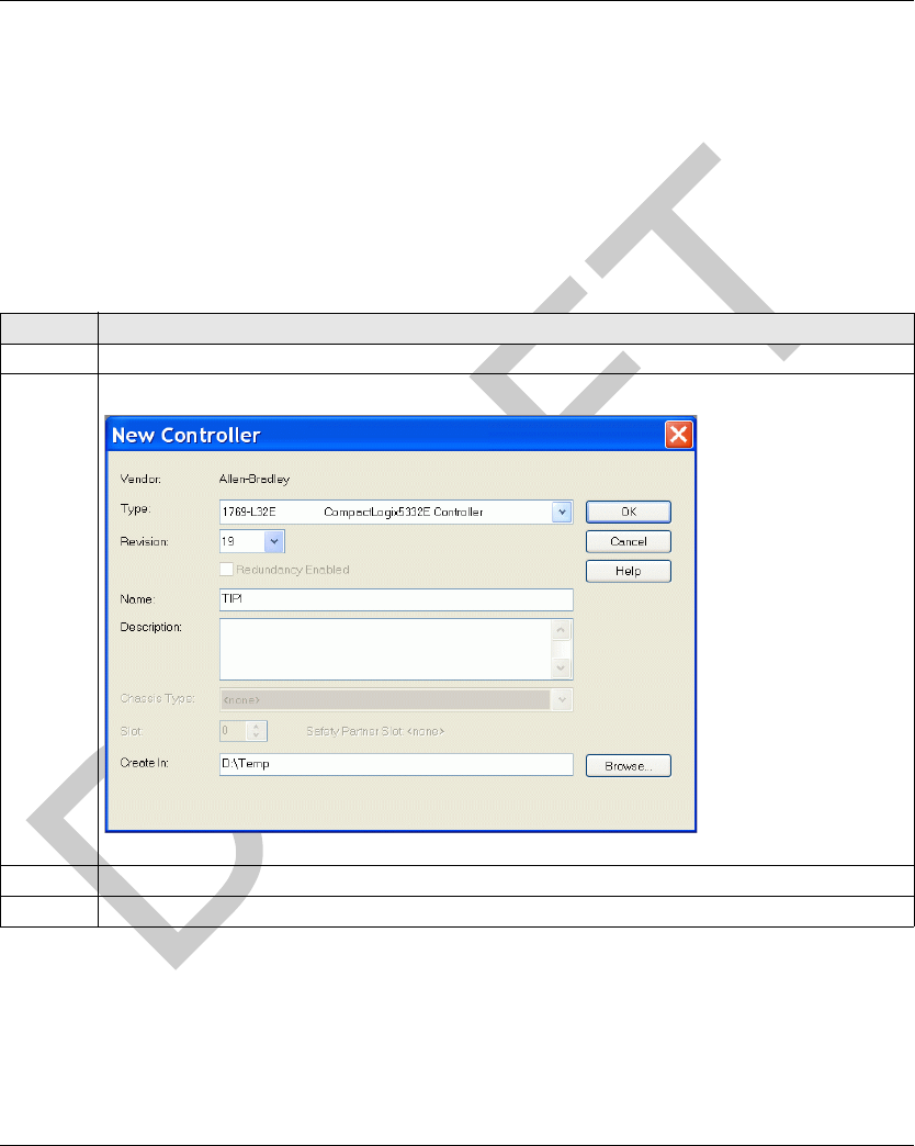
DI[D-SE-0029877.1.4] EtherNet/IP Communications Support
EIO0000001601 Draft 2013/07/17 83
Configuring a Smart Antenn a on an EtherNet/ IP Network with a ControlLogi x PLC
Configuring a Smart Antenna on an EtherNet/IP Network with a ControlLogix PLC
Introduction
This topic illustrates how to configure a Smart Antenna on an Ethernet/IP network to communicate
with an Allen Bradley ControlLogix PLC through an Ethernet cable.
ControlLogix PLC Setup
This table covers the steps necessary to program the ControlLogix PLC using RSLogix 5000
software:
Step Action
1 Start the RSLogix 5000 software.
2Select File → New. The New Controller dialog box opens.
3 Configure the controller by completing the required information.
4 Click OK.
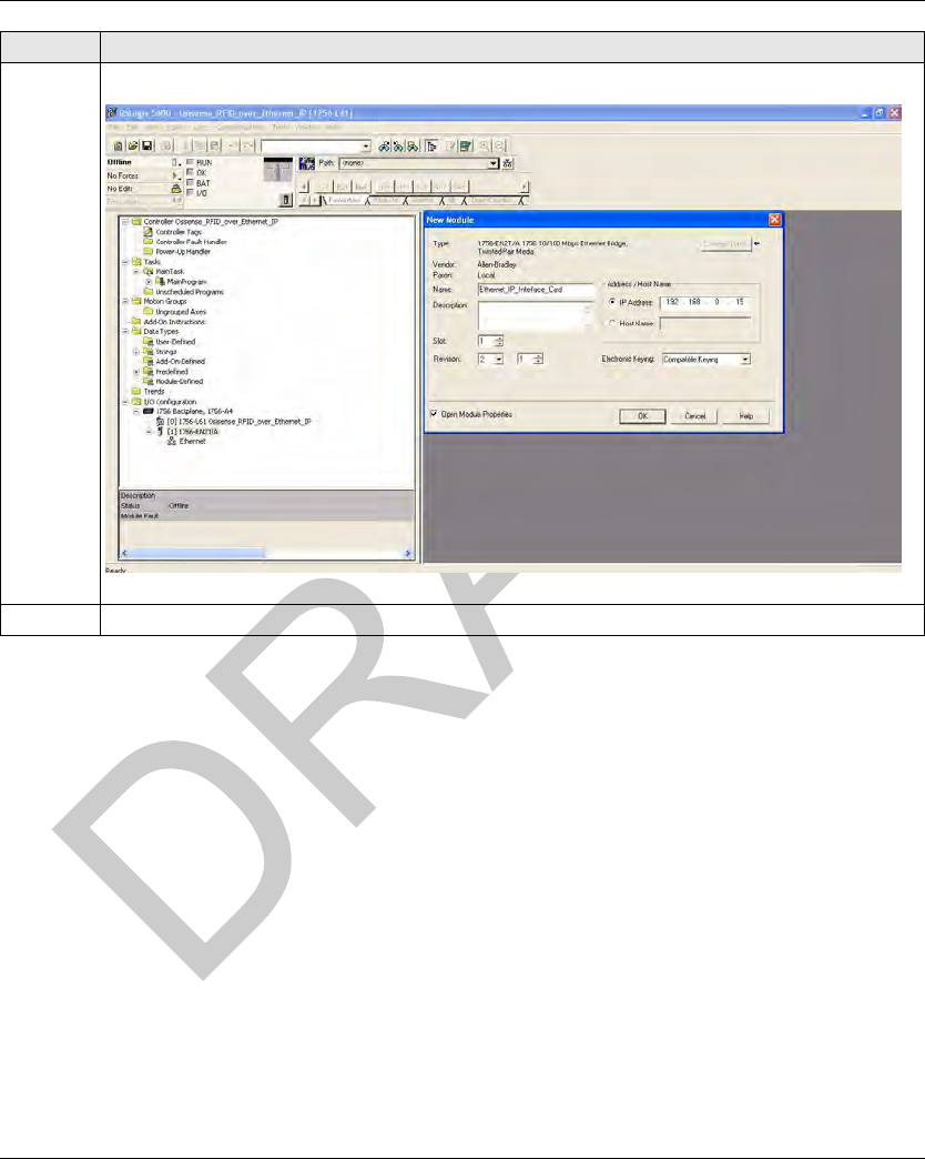
EtherNet/IP Communications Support DI[D-SE-0029877.1.4]
84 EIO0000001601 Draft 2013/07/17
5 Configure the Ethernet/IP card by completing the appropriate fields.
6 Click OK.
Step Action
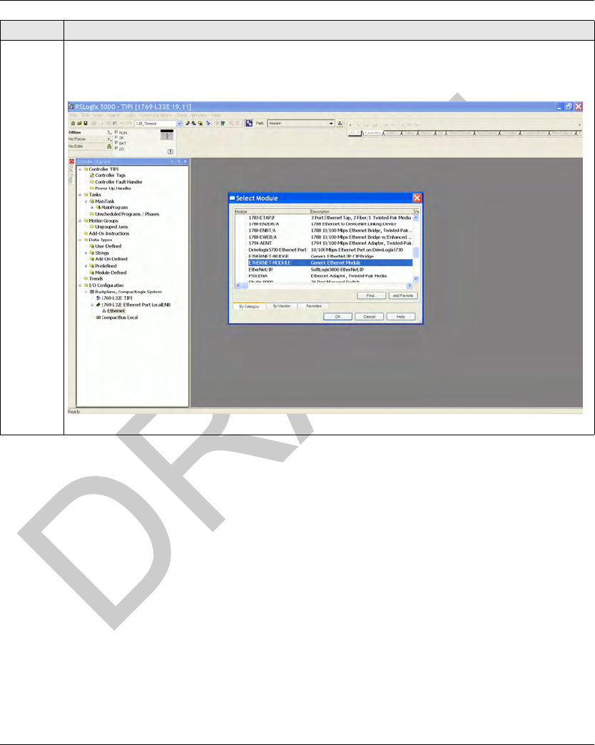
DI[D-SE-0029877.1.4] EtherNet/IP Communications Support
EIO0000001601 Draft 2013/07/17 85
7 Configure the communication module to communicate with the Smart Antenna:
From the Select Module dialog box, select ETHERNET-MODULE.
Click OK.
Step Action
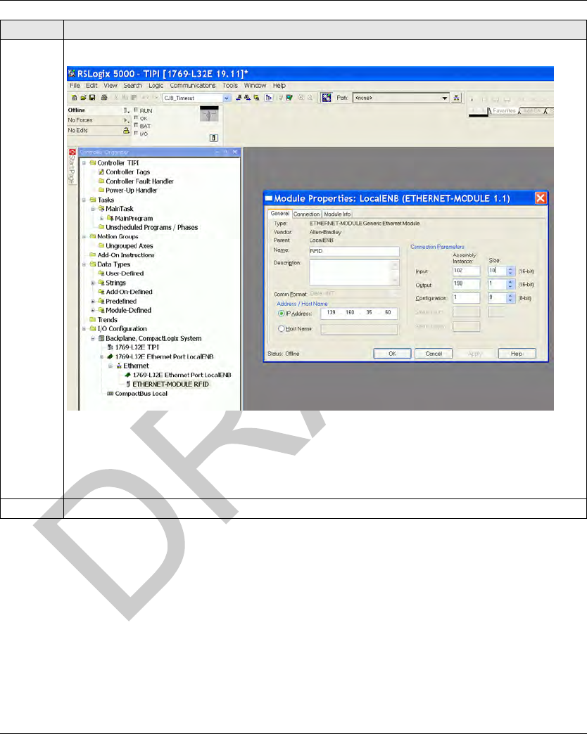
EtherNet/IP Communications Support DI[D-SE-0029877.1.4]
86 EIO0000001601 Draft 2013/07/17
8 Configure the Ethernet parameters to communicate with theSmart Antenna:
For the input parameters use:
Assembly Instance 102 (size 10) for the General status (see page 65),
or Assembly Instance 103 (size 100) for the Read table (see page 65).
For the output parameters, use the Assembly Instance 198 (size 1).
9 Select the Communication tab.
Step Action
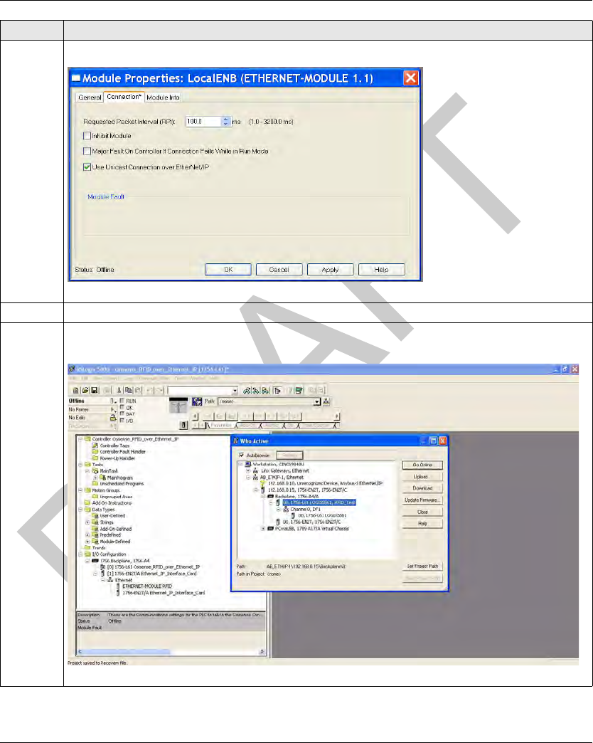
DI[D-SE-0029877.1.4] EtherNet/IP Communications Support
EIO0000001601 Draft 2013/07/17 87
10 Change the Requested Packet Interval (RPI) value to 10...100 ms.
11 Click OK.
12 Save and download the configuration to your ControlLogix PLC by selecting the module and clicking the
buttons on the Who Active dialog box to perform the various functions as necessary.
Step Action
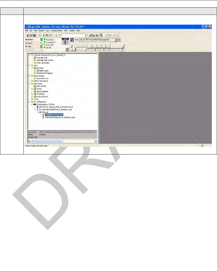
EtherNet/IP Communications Support DI[D-SE-0029877.1.4]
88 EIO0000001601 Draft 2013/07/17
13 When the download is complete, a prompt displays to place the ControlLogix PLC in Run Mode.
Step Action
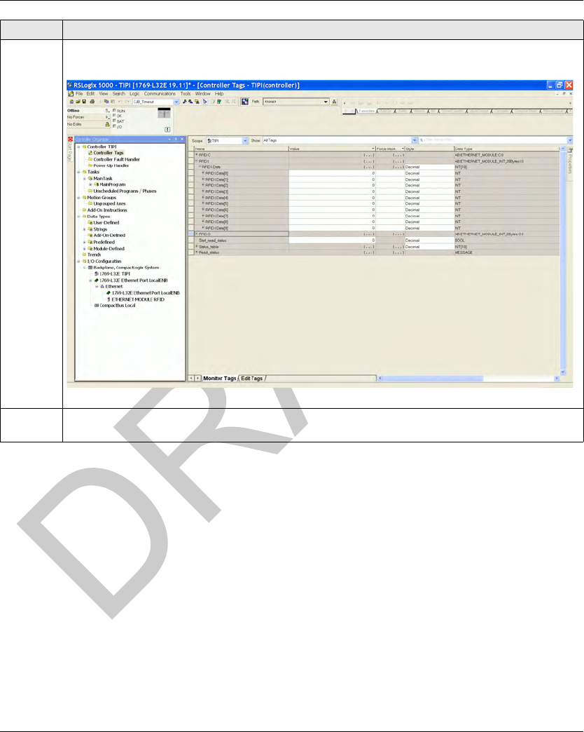
DI[D-SE-0029877.1.4] EtherNet/IP Communications Support
EIO0000001601 Draft 2013/07/17 89
14 Select Controller Tags from the navigation panel located on the left side of the window. The controller
tags that are used to communicate with the Smart Antenna appear on the right side of the window.
15 The configuration of the communication from a ControlLogix PLC to a Smart Antenna system using the
Ethernet/IP protocol is complete.
Step Action
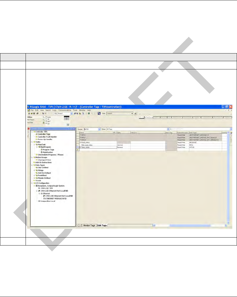
EtherNet/IP Communications Support DI[D-SE-0033416.1.4]
90 EIO0000001601 Draft 2013/07/17
Read the Assembly 102 (General Status) or 103 (Read Table) Using an Explicit Message
Read the Assembly 102 (General Status) or 103 (Read Table) Using an Explicit
Message
Procedure
This table covers the steps necessary to read the assembly 102 or 103 with an explicit message:
Step Action
1 In the Controller Organizer, open the Controller Tags and select the Edit Tags tab.
2 Create the following tags:
Read_status (type: MESSAGE)
Start_read_status (type: BOOL), in order to manage the message block
Status_table (type: array of INT), the length depends on the assembly (10 for the assembly 102,
100 for the assembly 103)
3 In the Controller Organizer → MainRoutine, create a new rung.
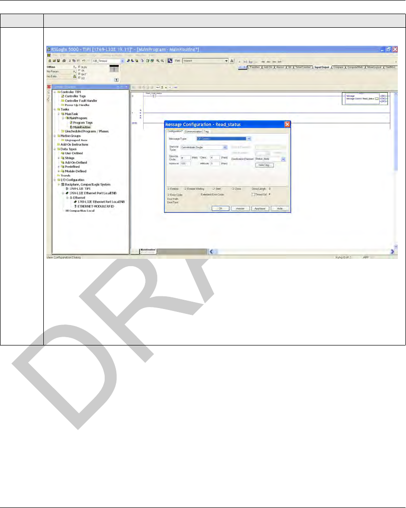
DI[D-SE-0033416.1.4] EtherNet/IP Communications Support
EIO0000001601 Draft 2013/07/17 91
4 Insert a message block MSG (available in the Input/Output tab):
Configure the message element:
Message Type: CIP Generic
Service Type: Get Attribute Single
Service Code: e
Class: 4
Instance: 102 or 103
Attribute: 3
Step Action
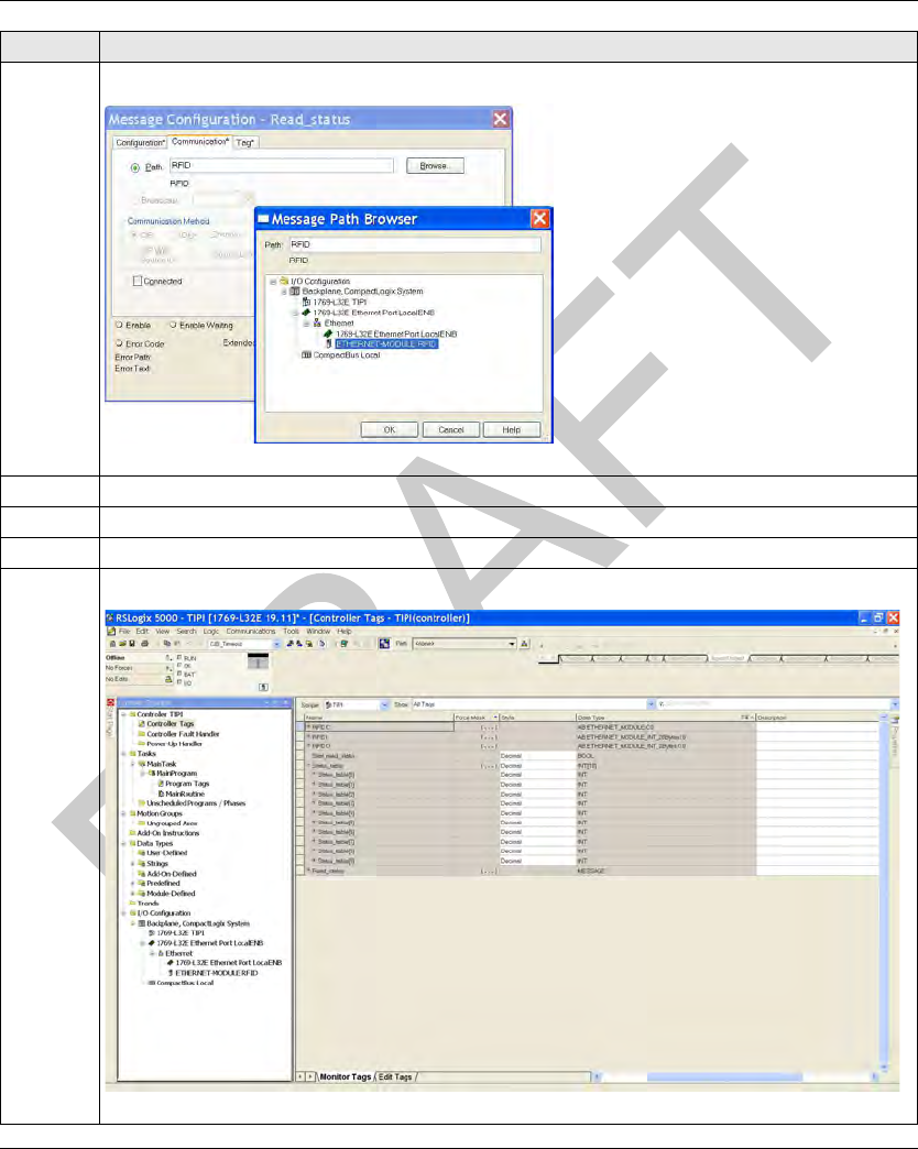
EtherNet/IP Communications Support DI[D-SE-0033416.1.4]
92 EIO0000001601 Draft 2013/07/17
5 Select the Communication tab and configure the communication path using the browser:
6 Click OK.
7 Save and download the application to the PLC.
8 When the download is complete, a prompt displays to place the PLC in Run Mode.
9 Click Controller Organizer → Controller Tags and select the Monitor Tags tab:
Step Action

DI[D-SE-0033416.1.4] EtherNet/IP Communications Support
EIO0000001601 Draft 2013/07/17 93
10 Use the Start_read_status bit to manage the message block.
Result: The assembly data are returned in the Status_table array.
Step Action
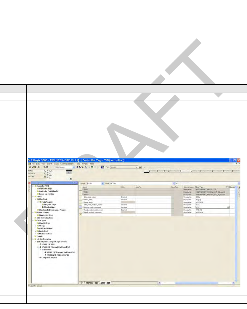
EtherNet/IP Communications Support DI[D-SE-0033425.1.1]
94 EIO0000001601 Draft 2013/07/17
Reading/Wr iting Request with the Modb us Object
Reading/Writing Request with the Modbus Object
Introduction
These Modbus explicit commands must be used to manage the tag and the Smart Antenna
memory zones (seepage48).
Reading Request with the Modbus Object and an Explicit Message
This table explains how to use the Modbus object (seepage67) for reading with an explicit
message:
Step Action
1 In the Controller Organizer, open the Controller Tags and select the Edit Tags tab.
2 Create the needed tags:
Read_modbus_command (type: MESSAGE)
Start_read_modbus_object (type: BOOL), in order to manage the message block
Modbus_data_command (type: array of 2 INT), data of the read Modbus command:
First word: starting address
Second word: quantity of registers to read
Read_modbus_table_result (type: array of INT), the length depends on the quantity of the
register to read (123 words maximum)
3 In the Controller Organizer → MainRoutine, create a new rung.
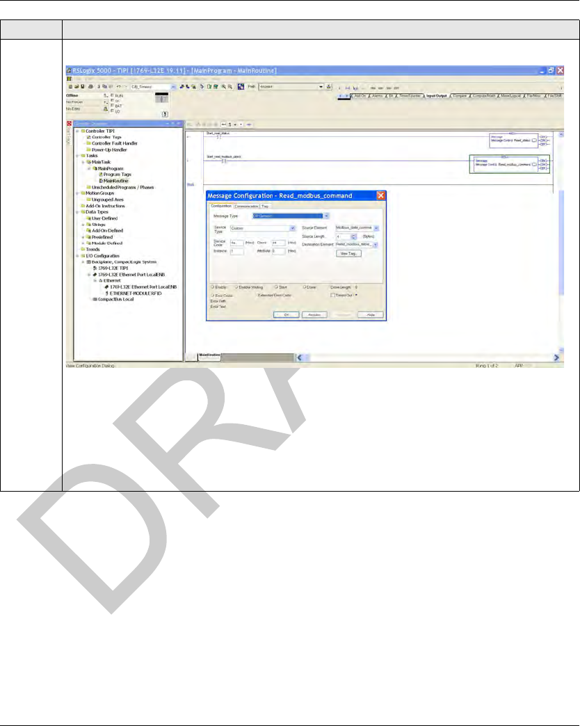
DI[D-SE-0033425.1.1] EtherNet/IP Communications Support
EIO0000001601 Draft 2013/07/17 95
4 Insert a message block MSG (available in the Input/Output tab):
Configure the message element:
Message Type: CIP Generic
Service Type: Custom
Service Code: 4e
Class: 44
Instance: 1
Attribute: 0
Step Action
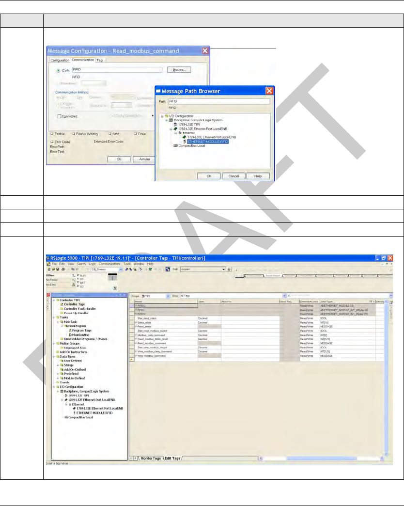
EtherNet/IP Communications Support DI[D-SE-0033425.1.1]
96 EIO0000001601 Draft 2013/07/17
5 Select the Communication tab and configure the communication path using the browser:
6Click OK.
7 Save and download the application to the PLC.
8 When the download is complete, a prompt displays to place the PLC in Run Mode.
9Click Controller Organizer → Controller Tags and select the Monitor Tags tab:
Step Action

DI[D-SE-0033425.1.1] EtherNet/IP Communications Support
EIO0000001601 Draft 2013/07/17 97
Writing Request with the Modbus Object and an Explicit Message
This table explains how to use the Modbus object (see page 67) for writing with an explicit
message:
10 Use the Start_read_status bit to manage the message block.
Result: The result of the reading request is retuned in the Read_modbus_table_result array.
Step Action
Step Action
1 In the Controller Organizer, open the Controller Tags and select the Edit Tags tab.
2 Create the needed tags:
Write_modbus_command (type: MESSAGE)
Start_write_modbus_object (type: BOOL), in order to manage the message block
Write_Modbus_data_command (type: array of N INT), data of the write Modbus command (the
length depends on the quantity of the register to write):
First word: starting address
Second word: quantity of registers to write
Third...N word: data to write
3 In the Controller Organizer → MainRoutine, create a new rung.
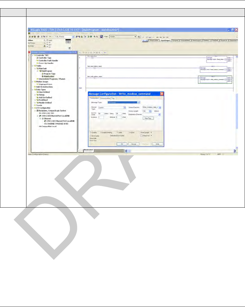
EtherNet/IP Communications Support DI[D-SE-0033425.1.1]
98 EIO0000001601 Draft 2013/07/17
4 Insert a message block MSG (available in the Input/Output tab):
Configure the message element:
Message Type: CIP Generic
Service Type: Custom
Service Code: 50
Class: 44
Instance: 1
Attribute: 0
Step Action
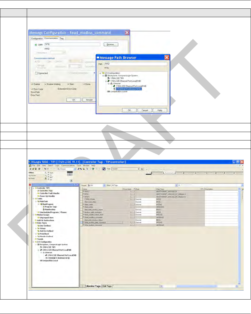
DI[D-SE-0033425.1.1] EtherNet/IP Communications Support
EIO0000001601 Draft 2013/07/17 99
5 Select the Communication tab and configure the communication path using the browser:
6 Click OK.
7 Save and download the application to the PLC.
8 When the download is complete, a prompt displays to place the PLC in Run Mode.
9 Click Controller Organizer → Controller Tags and select the Monitor Tags tab:
Step Action

EtherNet/IP Communications Support DI[D-SE-0033425.1.1]
100 EIO0000001601 Draft 2013/07/17
10 Place the data to write in the Write_modbus_data_command array.
Use the Start_write_modbus_object bit to manage the message block.
Step Action

EIO0000001601 Draft 2013/07/17 101
DI[D-SE-0030485.1.1]
RFID OsiSens e® XG
Modbus TCP/IP Communications Support
EIO0000001601 Draft 2013/07/17
Modbus TCP/IP Communications Support
Chapter 6
Modbus TCP/IP Communications Support
Modbus TCP/IP Communications Support
Introduction
This chapter describes how a Smart Antenna can be accessed from other devices on a Modbus
TCP/IP fieldbus network.
What Is in This Chapter?
This chapter contains the following topics:
Topic Page
Modbus Commands Supported by the Smart Antenna 102
Modbus Requests Description 107
Modbus Application Example 111

Modbus TCP/IP Communications Support DI[D-SE-0030483.1.6]
102 EIO0000001601 Draft 2013/07/17
Modbus Comm ands Support ed by the Sma rt Antenna
Modbus Commands Supported by the Smart Antenna
Introduction
Modbus is the protocol used by Modicon PLCs. Modbus defines the message structure that the
PLCs understand and use, regardless of network type. The Modbus protocol describes the process
that a controller uses to access another device, how that device responds, and how detected errors
are reported.
The Smart Antenna is a server on a Modbus TCP system.
It can be connected to any system with Modbus TCP clients, including these:
PLC (function blocks or I/O scanner)
HMI
SCADA
Computer
The Unit ID of the Smart Antenna on Modbus TCP is fixed to 1, the Smart Antenna is addressed
by its IP address.
Modbus Message Data Frame
Modbus messages are embedded within the frame or packet structure of the network in use. A
Modbus over TCP/IP network uses both the Ethernet II and IEEE 802.3 data formats. For
communications with the Smart Antenna, Modbus messages can be embedded in either frame
type. Ethernet II is the default data format.
Modbus Message Structure
The Modbus protocol uses a 16-bit word. A Modbus message begins with a header. A Modbus
message uses a Modbus function code (see page 102) as the first byte.
Following is a description of the structure of a Modbus message header:
List of Supported Commands
The table lists the Modbus commands that the Smart Antenna supports:
Invoke Identifier Protocol Type Command Length Destination ID Modbus Message
two-byte field that
associates a request
with a response
two-byte field
value for Modbus is
always 0
two-byte field
value is the size of the
rest of the message
one-byte n-byte field
first byte is the Modbus
function code
Modbus Function
Code
Subfunction or
Subindex
Command
03h - Read n words (1 ≤ n ≤ 123)
06h - Write one word
08h 16h Get/clear Ethernet statistics (see page 103)
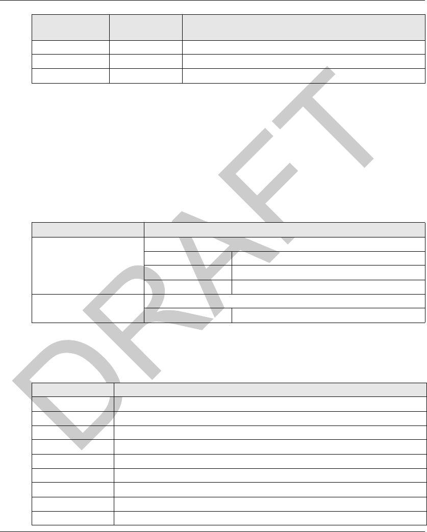
DI[D-SE-0030483.1.6] Modbus TCP/IP Communications Support
EIO0000001601 Draft 2013/07/17 103
Ethernet Statistics
Ethernet statistics comprise status information and errors related to data transmissions to and from
the Smart Antenna over the Ethernet LAN.
Ethernet statistics are held in a buffer until the get Ethernet statistics command is issued, and
the statistics are retrieved.
The clear Ethernet statistics command clears all of the statistics currently held in the buffer
except the MAC address and the IP address.
When issuing a command, it is necessary to include a diagnostic control word that contains the
following required information:
Basic Network Diagnostics
Basic network diagnostic data can be accessed at the following Modbus register addresses,
relative to the initial address offset value:
0Bh - Read event counters
10h - Write n words (1 ≤ n ≤ 123)
2Bh 0Eh ID
Modbus Function
Code
Subfunction or
Subindex
Command
Diagnostic Control Byte Description
MSB: bits 15...8 Data selection code:
01h Basic network diagnostics (see page 103)
02h Ethernet port diagnostics (see page 104)
03h Modbus TCP/Port 502 diagnostics (see page 105)
LSB: bits 7...0 Port selection code
01...FFh The logical number of the port
Address: Offset + Description
0–1 basic network diagnostic validity
2 communication global status
3 supported communication services
4 status of communication services
5–6 IP address
7–8 subnet mask
9–10 default gateway
11–13 MAC address
14–16 Ethernet frame format capability/configuration/operational

Modbus TCP/IP Communications Support DI[D-SE-0030483.1.6]
104 EIO0000001601 Draft 2013/07/17
Ethernet Port Diagnostics
Ethernet port diagnostic data can be accessed at the following Modbus register addresses, relative
to the initial address offset value:
17–18 Ethernet receive frames OK
19–20 Ethernet transmit frames OK
21 number of open client connections
22 number of open server connections
23–24 number of Modbus exception responses
25–26 number of Modbus messages sent
27–28 number of Modbus messages received
29–36 device name
37–38 IP assignment mode capability/operational
Address: Offset + Description
Address: Offset + Description
0 port diagnostics data validity
1 logical/physical port number
2 Ethernet control capability
3 link speed capability
4 Ethernet control configuration
5 link speed configuration
6 Ethernet control operational
7 link speed operational
8–10 port MAC address
11–12 media counters data validity
13–14 number of frames transmitted OK
15–16 number of frames received OK
17–18 number of Ethernet collisions
19–20 detected carrier sense errors
21–22 number of Ethernet excessive collisions
23–24 detected CRC errors
25–26 detected FCS errors
27–28 detected alignment errors
29–30 number of detected internal MAC Tx errors
31–32 late collisions

DI[D-SE-0030483.1.6] Modbus TCP/IP Communications Support
EIO0000001601 Draft 2013/07/17 105
Modbus TCP/Port 502 Diagnostics
Modbus TCP/Port 502 diagnostic data can be accessed at the following Modbus register
addresses, relative to the initial address offset value:
33–34 detected internal MAC Rx errors
35–36 multiple collisions
37–38 single collisions
39–40 deferred transmissions
41–42 frames too long
43–44 frames too short
45–46 detected SQE test error(s)
47 interface counters diagnostic validity
48–49 number of octets received
50–51 number of unicast packets received
52–53 number of non-unicast packets received
54–55 number of inbound packets discard
56–57 number of detected inbound packet errors
58–59 number of unknown inbound packets
60–61 number of octets sent
62–63 number of unicast packets sent
64–65 number of non-unicast packets sent
66–67 number of outbound packets discarded
68–69 number of detected outbound packet errors
Address: Offset + Description
Address: Offset + Description
0–1 Modbus TCP/port 502 diagnostic data validity
2 port 502 status
3 number of open connections
4–5 number of Modbus messages sent
6–7 number of Modbus messages received
8 number of Modbus open client connections
9 number of Modbus open server connections
10 maximum number of connections
11 maximum number of client connections
12 maximum number of server connections

Modbus TCP/IP Communications Support DI[D-SE-0030483.1.6]
106 EIO0000001601 Draft 2013/07/17
13–14 number of Modbus exception responses
15 number of open priority connections
16 maximum number of priority connections
17 number of entries in unauthorized table
18–19 remote IP address 1 Table entry 1
20 number of attempts to open unauthorized connection 1
...
111–112 remote IP address 32 Table entry 32
113 number of attempts to open unauthorized connection 32
Address: Offset + Description
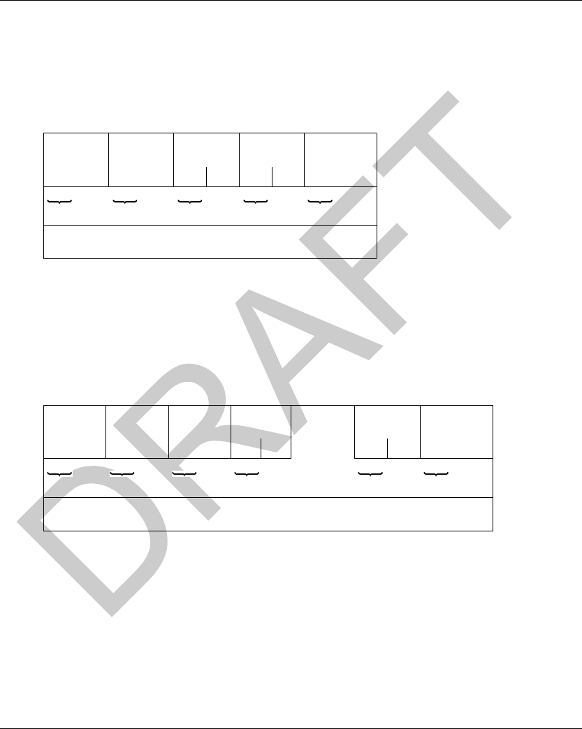
DI[D-SE-0030484.1.5] Modbus TCP/IP Communications Support
EIO0000001601 Draft 2013/07/17 107
Modbus Requ ests Descript ion
Modbus Requests Description
Read N Words
This function is used to read objects (word, word string).
Read request:
Slave no.: 01h
Function code: 3h
Address of first word: Corresponds to the address of the first word to be read in the tag or the
Smart Antenna (depending on the address)
Number of words: 1 ≤ N ≤ 123
Response:
Slave no.: 01h
Function code: Same as read request
Number of bytes read: 2 to 246
Value of the words read: 0000h to FFFFh
If there is no tag present, the Smart Antenna sends a detected error report (Error messages
(seepage109)).
Slave no. Function
code
Address of
1st word
Number of
words
Check
01h 3h Hi Lo Hi Lo
1byte 1byte 2bytes 2bytes 2bytes
(RTU mode)
Slave no. Function
code
Number of
bytes read
Value of
1st word
Value of
last word
Check
01h 3h or 4h Hi Lo Hi Lo
1 byte 1 byte 1 byte 2 bytes 2 bytes 2 bytes
(RTU mode)
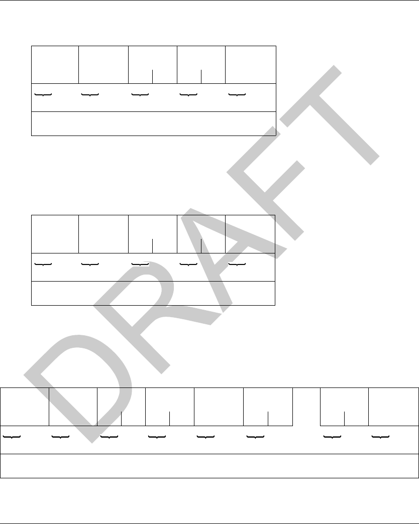
Modbus TCP/IP Communications Support DI[D-SE-0030484.1.5]
108 EIO0000001601 Draft 2013/07/17
Write One Word
Write request:
Slave no.: 01h
Function code: 6h
Address of word: Same addressing field as for the read request
Word values: 0000h to FFFFh
Response:
The response is an echo of the request, indicating that the value contained in the request has been
taken into account by the Smart Antenna.
Write N Words
Write request:
Slave no.: 01h
Function code: 10h
Slave no. Function
code
Address of
word
Word Value Check
01h 6h Hi Lo Hi Lo
1byte 1byte 2bytes 2bytes 2bytes
(RTU mode)
Slave no. Function
code
Address of
word
Word Value Check
01h 6h Hi Lo Hi Lo
1byte 1byte 2bytes 2bytes 2bytes
(RTU mode)
Slave no. Function
code
Address of
1st word
Number of
words
Number of
bytes
Value of 1st
word
Value of
last word
Check
01h 10h Hi Lo Hi Lo Hi Lo Hi Lo
1 byte 1 byte 2 bytes 2 bytes 1 byte 2 bytes 2 bytes 2 bytes
(RTU mode)
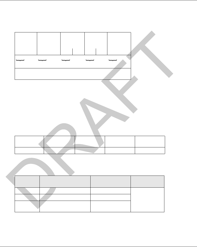
DI[D-SE-0030484.1.5] Modbus TCP/IP Communications Support
EIO0000001601 Draft 2013/07/17 109
Number of words: 1 ≤ N ≤ 123
Number of bytes: Twice the number of words
Word values: 0000h to FFFFh
Response:
Slave no.: 01h
Function code: Same as request
Address of first word written: Same as request
Number of words written: Same as request
Identification Request
Function 2Bh: This function is used to identify the Smart Antenna.
Read request:
* : MEI = Modbus Encapsulated Interface
Response:
Detected Error Messages
When an anomaly in the message (or during its execution) is detected by the Smart Antenna to
which it is addressed, the Smart Antenna sends back a detected error message to the master
system.
Slave no. Function
code
Address of
1st word
written
Number of
words
written
Check
01h 10h Hi Lo Hi Lo
1byte 1byte 2bytes 2bytes 2bytes
(RTU mode)
Slave no. Function code MEI * Read Device ID
code
Object ID
01h 2Bh 0Eh 01h, 02h, 03h 00h
Index Object Name &
Description
Description Data Type
0 (0000h) Manufacturer name TELEMECANIQUE ASCII string
1 (0001h) Product code
2 (0002h) Version number Vx.y (for example:
V3.6)

Modbus TCP/IP Communications Support DI[D-SE-0030484.1.5]
110 EIO0000001601 Draft 2013/07/17
Syntax:
Slave no.: 01h
Function code: Same as the function code and most significant bit of the byte set at 1
Examples:
Function code of the detected error message after a read request:
83h = (80 + 03) or 84h = (80 + 04)
Function code of the detected error message after a write request:
90h = (80 + 10)
Detected error code:
1h: Unknown function code or incorrect request format
2h: Incorrect address or prohibited zone or protected zone or address outside the tag memory
zone
3h: Incorrect data too much or not enough data in the frame, or quantity = 0, or data
incompatible
4h: Execution detected error (in read or write mode, or tag missing)
Slave no. Function
code
Detected
error code
Check
1 byte 1 byte 1 byte 2 bytes
(RTU mode)
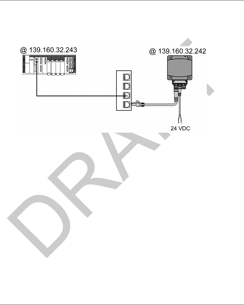
DI[D-SE-0030825.1.3] Modbus TCP/IP Communications Support
EIO0000001601 Draft 2013/07/17 111
Modbus Appli cation Exampl e
Modbus Application Example
Application Example
A Smart Antenna and a Premium PLC are connected to a Modbus TCP/IP network.
PLC Configuration with Unity Pro XL
To enable communication between these 2 devices, the PLC hardware configuration must be
entered, giving:
An XWAY address for the Smart Antenna
The IP address of the Smart Antenna
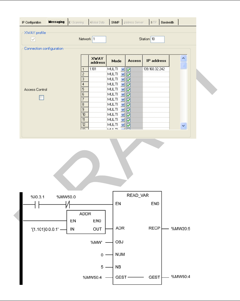
Modbus TCP/IP Communications Support DI[D-SE-0030825.1.3]
112 EIO0000001601 Draft 2013/07/17
The figure illustrates the configuration in Unity Pro:
Example of Program in Unity Pro
Program example: Read 5 words in the tag starting at word %MW0 of the tag.
NOTE: The Modbus address of the Smart Antenna is 1 (fixed address).
LADDER programming
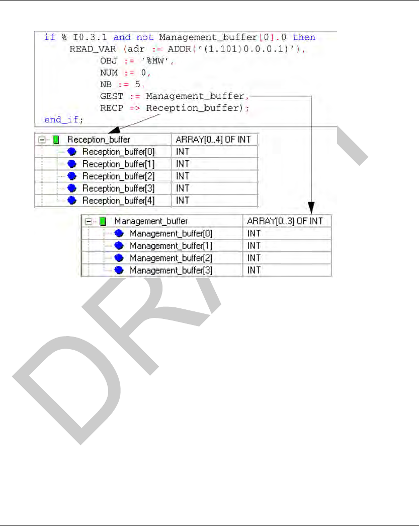
DI[D-SE-0030825.1.3] Modbus TCP/IP Communications Support
EIO0000001601 Draft 2013/07/17 113
Structured Text programming
NOTE: The ADDR function is structured: ‘(XWAY address)Rack.Module.Channel.Modbus
address)’.

Modbus TCP/IP Communications Support DI[D-SE-0030825.1.3]
114 EIO0000001601 Draft 2013/07/17

EIO0000001601 Draft 2013/07/17 115
DI[D-SE-0030505.1.1]
RFID OsiSens e® XG
Web Server
EIO0000001601 Draft 2013/07/17
Web Server
Chapter 7
Web Server
Web Server
Aim of This Chapter
This chapter describes the Smart Antenna web server.
What Is in This Chapter?
This chapter contains the following topics:
Topic Page
Web Server Access 116
Setup Pages 118
Documentation Web Page 123
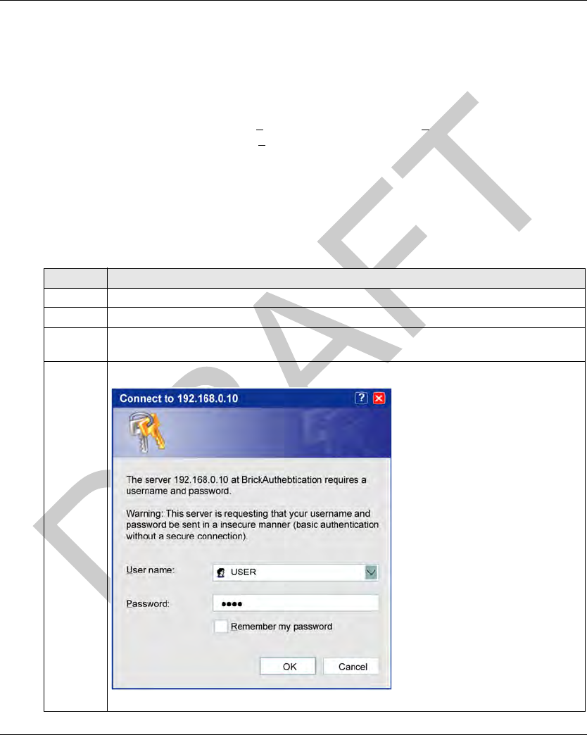
Web Server DI[D-SE-0030704.1.9]
116 EIO0000001601 Draft 2013/07/17
Web Ser ver Access
Web Server Access
Introduction
To access the Smart Antenna web server, you need:
Microsoft Windows XP or 7,
Microsoft Internet Explorer version > 8 or Mozilla Firefox version > 19,
Java Runtime environment version > 7.
Before you begin, be sure that both your PC and the Smart Antenna are configured with IP
addresses that are located in the same subnet (or, alternatively, are connected via a routing
mechanism).
Accessing the Smart Antenna Embedded Web Server
The procedure describes how to access the embedded web server:
Step Action
1 Connect the Smart Antenna to a PC.
2 Open a web browser.
3 Enter the Smart Antenna factory setting address: http://192.168.0.10 in the address line of the
browser and hit Enter on your keyboard.
4 A dialog box opens and prompts you for a user name and password.
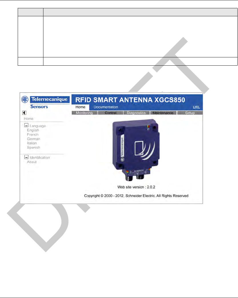
DI[D-SE-0030704.1.9] Web Server
EIO0000001601 Draft 2013/07/17 117
Home Page Description
The graphic shows the Smart Antenna web server Home page:
The Home page gives access to the following web service pages:
Setup (see page 118)
Diagnostics (see page 128)
Monitoring (see page 128)
Documentation (seepage123)
5 Enter the factory default settings for User name and Password:
User name = USER
Password = USER
NOTE: If you previously changed the password, you must instead enter the new password in
this dialog box.
6 Click OK. The web server home page is displayed.
Step Action
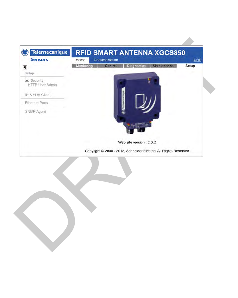
Web Server DI[D-SE-0030818.1.7]
118 EIO0000001601 Draft 2013/07/17
Setup Pages
Setup Pages
Setup Home Page
The Setup home page looks like this:
From the Setup home page, you can access to the following pages:
WEB SECURITY (see page 119), to configure user accounts and passwords,
IP & FDR CONFIGURATION (seepage41), to configure the Smart Antenna IP address,
ETHERNET PORTS CONFIGURATION (see page 120), to configure the 2 ports of the Smart
Antenna,
SNMP AGENT CONFIGURATION (seepage120), to configure the SNMP agent.
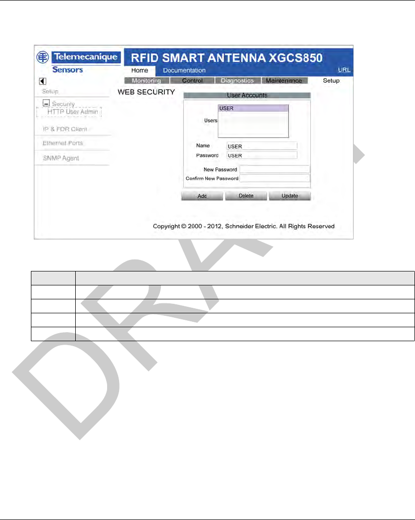
DI[D-SE-0030818.1.7] Web Server
EIO0000001601 Draft 2013/07/17 119
User Accounts Configuration
The WEB SECURITY (seepage119) page looks like this:
The procedure shows how to modify a user account:
Step Action
1In the Users list, select the account to modify.
2 Fill the fields Name and Password.
3 Enter the new password in the fields New Password and Confirm New Password.
4 Click Update to confirm the new settings.
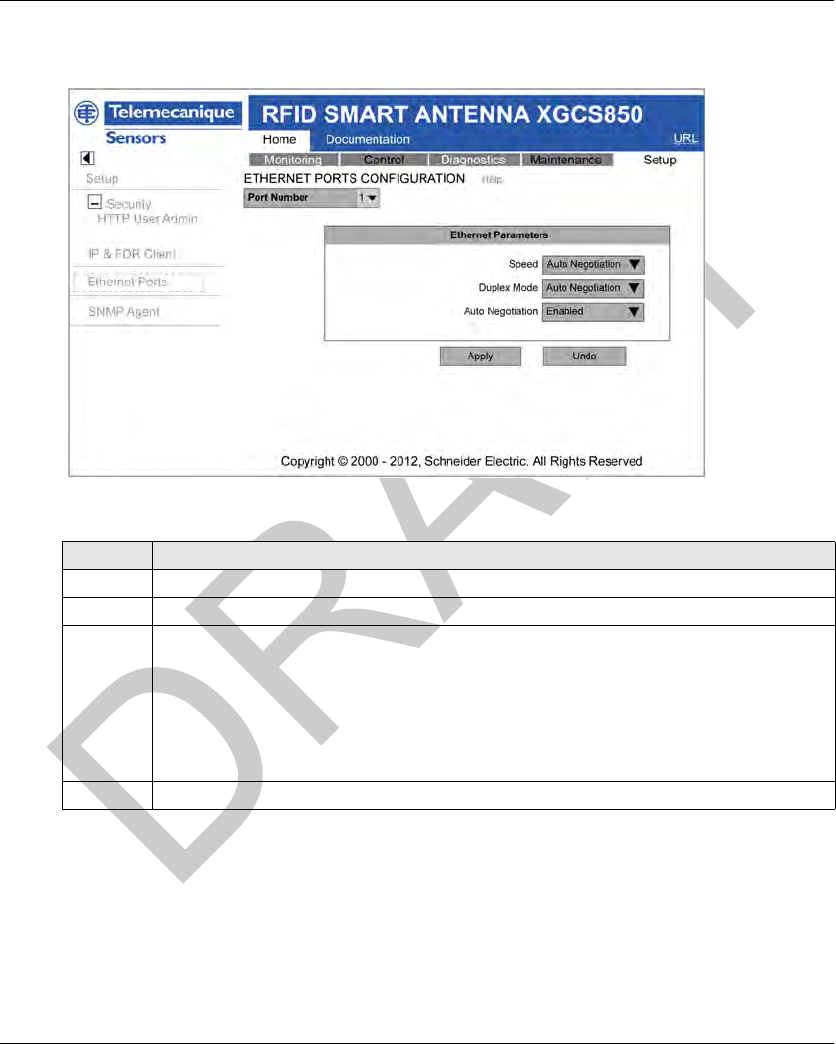
Web Server DI[D-SE-0030818.1.7]
120 EIO0000001601 Draft 2013/07/17
Ethernet Ports Configuration
The ETHERNET PORTS CONFIGURATION page looks like this:
The procedure shows how to configure Ethernet ports:
SNMP Agent Configuration
The Smart Antenna includes an SNMP agent that can connect to and communicate with an SNMP
manager through the UDP transport protocol over ports 161 and 162.
Step Action
1 Select the Port Number to configure (1 or 2).
2 Select the Auto Negotiation mode (enabled or disabled).
3 Configure the following parameters if the Auto Negotiation is disabled:
Speed
10 Mbit/s
100 Mbit/s
Duplex Mode
Half-duplex
Full-duplex
4 Click Apply to confirm the new settings.
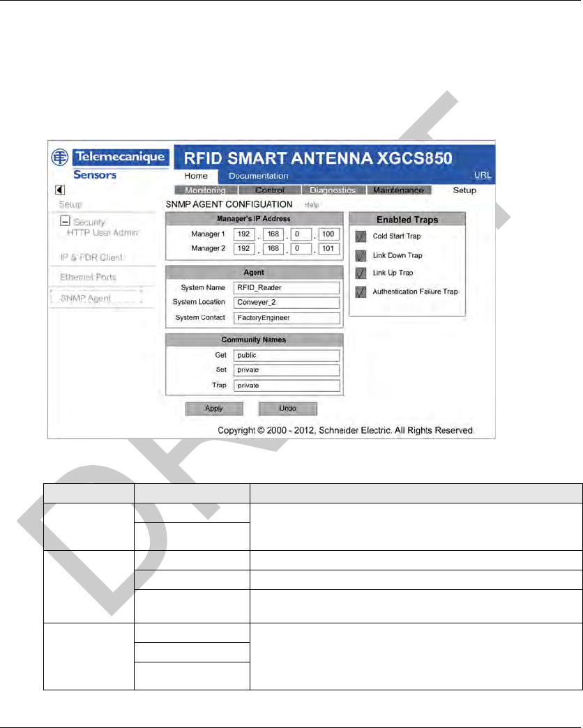
DI[D-SE-0030818.1.7] Web Server
EIO0000001601 Draft 2013/07/17 121
The SNMP service includes:
automatic discovery and identification of the Smart Antenna by an SNMP manager over an
Ethernet network,
authentication checking by the Smart Antenna of any SNMP manager that sends requests to it,
management of event (or trap) reporting by the Smart Antenna, including the identification of 2
SNMP managers authorized to receive reports.
The SNMP AGENT CONFIGURATION page looks like this:
The table describes the SNMP agent parameters:
Area Parameters Description
Manager’s IP
Address
Manager 1 IP addresses of the SNMP administrators. The Smart Antenna
allows a maximum of 2 administrators. These addresses are used
for transmitting events (trap).
Manager 2
Agent System Name Indicate the name of the Smart Antenna.
System Location Indicate the physical location of the Smart Antenna.
System Contact Indicate the person to contact for management of the Smart
Antenna
Community
Names
Get Define a password for the Set, Get, and Trap service families.
NOTE: The maximum password length is 16 printable ASCII
characters.
Set
Trap

Web Server DI[D-SE-0030818.1.7]
122 EIO0000001601 Draft 2013/07/17
The table describes the SNMP agent configuration:
Enabled Traps Cold Start Trap The event is sent when the Smart Antenna is powered up.
Link Down Trap One of the communication links of the agent has turned off.
Link Up Trap One of the communication links of the agent has turned on.
Authentication Failure
Trap
The agent received a request from an unauthorized manager.
Area Parameters Description
Step Action
1 In the Manager’s IP Address section, enter these values:
Manager 1: The IP address of the first SNMP manager.
Manager 2: The IP address of the second SNMP manager.
2 The following Agent fields are read-only ASCII strings:
System Name: This user-defined string describes the Smart Antenna.
System Location: This string describes the location of the Smart Antenna.
System Contact: This string identifies the contact person for the Smart Antenna.
NOTE: These case-sensitive strings have a maximum length of 32 characters.
3In the Community Names section, enter passwords for Get, Set, and Trap. (They can be
empty.)
NOTE: The maximum password length is 16 printable ASCII characters. The default setting for
Get is public and private for Set, and Trap.
4 In the Enabled Traps section, select one or more of the following traps to enable SNMP agent
reporting of that trap; de-select a trap to disable reporting:
Cold Start Trap: The agent is reinitializing and its configuration may be altered.
Link Down Trap: One of the communication links of the agent has turned off.
Link Up Trap: One of the communication links of the agent turned on.
Authentication Failure Trap: The agent received a request from an unauthorized manager.
5 Click one of the following:
Apply: Save your edits.
Undo: Clear the page without saving your edits.
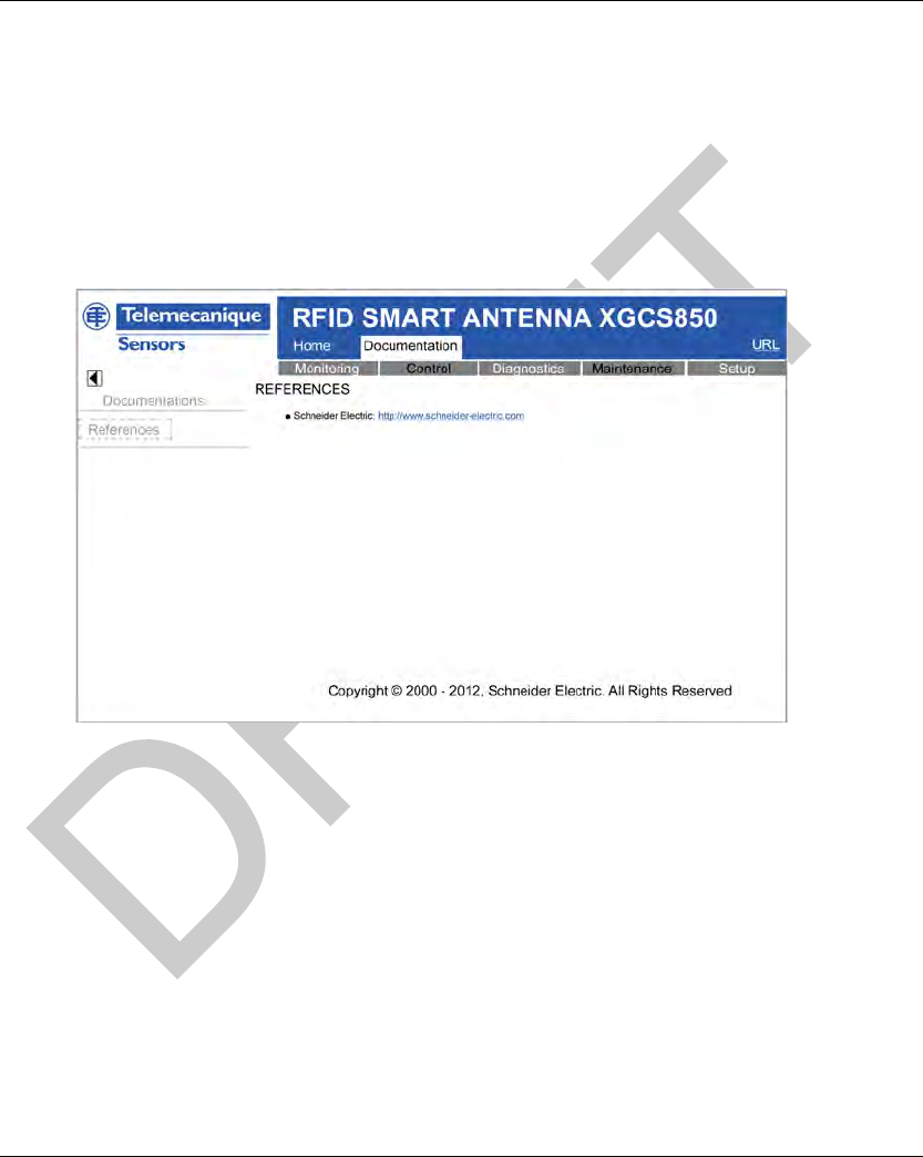
DI[D-SE-0030819.1.3] Web Server
EIO0000001601 Draft 2013/07/17 123
Documentatio n Web Page
Documentation Web Page
Introduction
The Documentation page of the embedded web server allows downloading the EDS file of the
Smart Antenna.
Description
The graphic shows the Smart Antenna web server Documentation page:
Click the EDS file to download it.

Web Server DI[D-SE-0030819.1.3]
124 EIO0000001601 Draft 2013/07/17

EIO0000001601 Draft 2013/07/17 125
DI[D-SE-0030486.1.2]
RFID OsiSens e® XG
Diagnost ics
EIO0000001601 Draft 2013/07/17
Diagnost ics
Chapter 8
Diagnostics
Diagnostics
Aim of This Chapter
This chapter describes how to diagnose a detected issue using the LEDs on the Smart Antenna or
by accessing the web server.
What Is in This Chapter?
This chapter contains the following topics:
Topic Page
Smart Antenna Diagnostic LEDs 126
Diagnostic Web Pages 128
Ethernet TCP/IP Statistics Page 129
Ethernet Port Statistics Page 130
Modbus TCP Port Statistics Page 131
Modbus TCP Messaging Statistics Page 132
SNMP Statistics Page 133
Diagnostic Log Page 134
Reader Diagnostics Page 135
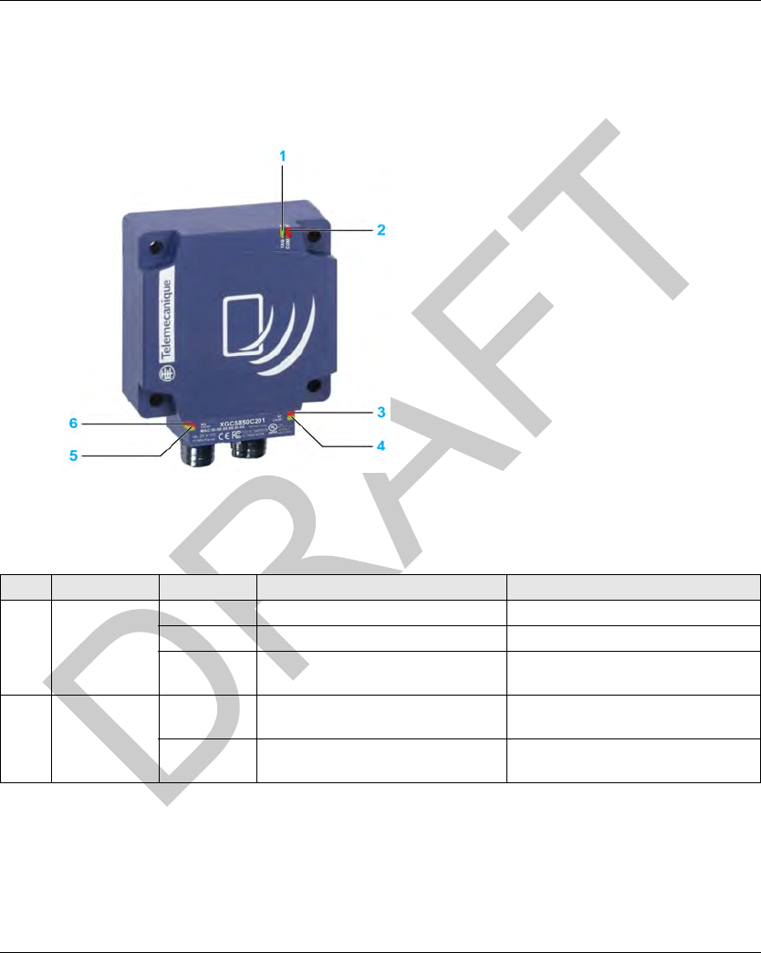
Diagnostics DI[D-SE-0030487.1.3]
126 EIO0000001601 Draft 2013/07/17
Smart An tenna Diagnostic L EDs
Smart Antenna Diagnostic LEDs
Introduction
The 6 two-tone LEDs display all the operating states of the Smart Antenna:
LEDs Description
The table describes the LEDs state:
LED Name LED State Description Smart Antenna State
1 TAG Solid green Tag presence A tag is detected, dialog ok
1 flash No tag detected Waiting for a tag
Red flashes RFID detected error Errors detected in the dialog with the
tag
2 COM Green
flashes
Requests received from a client Ok
Red flashes Detected error in requests received
from a client
Detected error code returned to the
client (no tag / bad parameters,...)

DI[D-SE-0030487.1.3] Diagnostics
EIO0000001601 Draft 2013/07/17 127
3 NS (Network
Status)
Steady off Not powered or no IP address Waiting for IP address setting (fixed or
DHCP).
Flashing
green
No connections No CIP connection established, and
an exclusive owner connection with a
client has not timed out.
Solid green Connected At least one CIP connection is
established, and an exclusive owner
connection with client has not timed
out.
Flashing red Connection timeout An exclusive owner connection with
client has timed out.
Solid red Duplicate IP The Smart Antenna has detected that
its IP address is already in use.
Flashing
green/red
Self-test The Smart Antenna is performing its
power-on self test.
4
5
Link Activity
(port 1 and 2)
Solid green Ethernet link present at 100 Mbit/s Ok
Flashing
green
Traffic at 100 Mbit/s Ok
Solid yellow Ethernet link present at 10 Mbit/s Ok
Flashing
yellow
Traffic at 100 Mbit/s Ok
6 MS (Ethernet
module status)
Solid green The Ethernet module of the Smart
Antenna is operational
Ok
Flashing
green
Standby The Smart Antenna is waiting for
network configuration.
Flashing red Minor detected fault The Smart Antenna has detected a
recoverable minor fault.
NOTE: An incorrect or inconsistent
configuration is considered as a minor
detected fault.
Steady red Major detected fault The Smart Antenna has detected a
non-recoverable major fault on its
Ethernet module.
Flashing
green/red
Self-test The Smart Antenna is performing its
power-on self test.
LED Name LED State Description Smart Antenna State
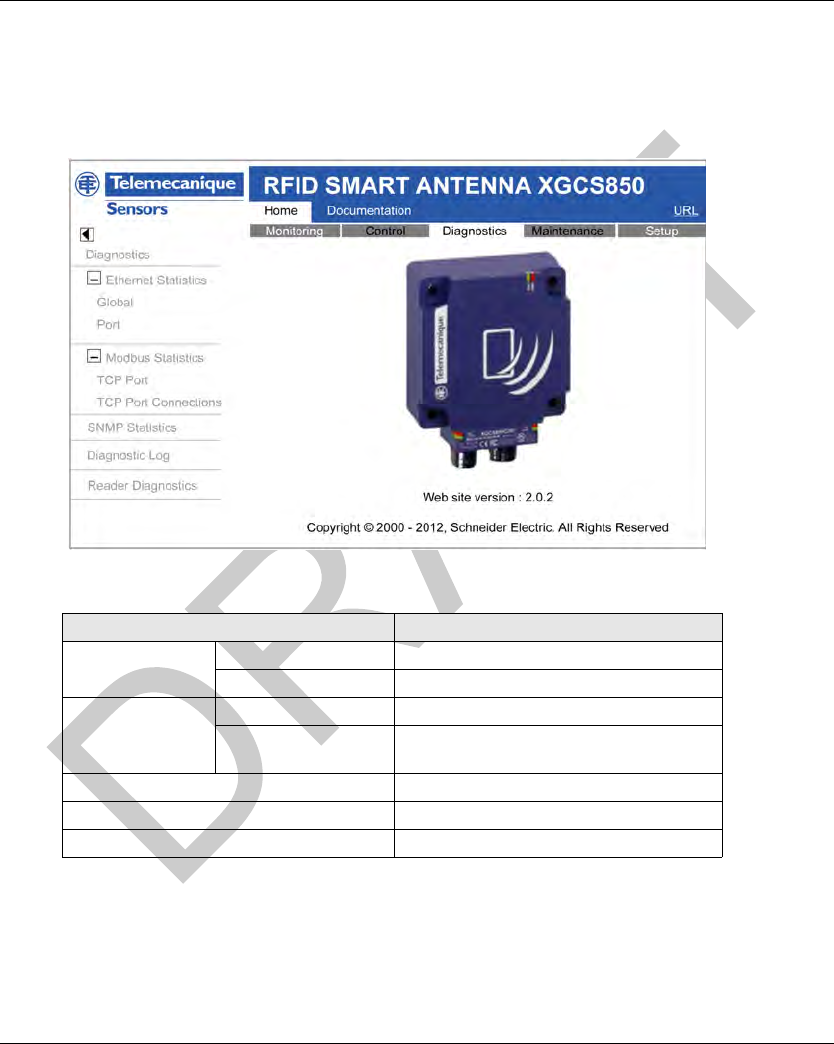
Diagnostics DI[D-SE-0030503.1.4]
128 EIO0000001601 Draft 2013/07/17
Diagnostic We b Pages
Diagnostic Web Pages
Diagnostic Home Page
The Diagnostic home page looks like this:
Links on the left display and access embedded web pages for the selected function:
Link Corresponding Embedded Web Page
Ethernet Statistics Global Ethernet TCP/IP Statistics (see page 129)
Port Ethernet Port Statistics (seepage130)
Modbus Statistics TCP Port Modbus TCP Port Statistics (see page 131)
TCP Port Connections Modbus TCP Messaging Statistics
(see page 132)
SNMP Statistics SNMP Statistics (see page 133)
Diagnostic Log Diagnostic Log (seepage134)
Reader Diagnostics Reader Diagnostics (see page 135)
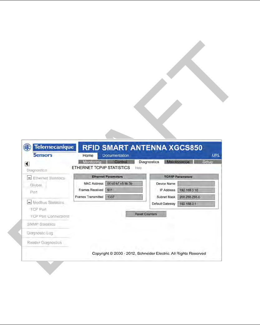
DI[D-SE-0032296.1.3] Diagnostics
EIO0000001601 Draft 2013/07/17 129
Ethernet TCP/IP Statistics Page
Ethernet TCP/IP Statistics Page
Description
On the left side of the page, under Ethernet Statistics, select Global to open the Ethernet TCP/IP
Statistics page.
Use the Ethernet TCP/IP Statistics page to:
Display the following information about the Smart Antenna:
device name,
MAC address,
IP addressing parameters (see page 40),
the number of Ethernet frames successfully received by both Ethernet ports on the module,
the number of Ethernet frames successfully transmitted by both Ethernet ports on the
module.
Click the Reset Counters button to reset the Frames Received and Frames Transmitted
counting statistics to 0.
The counting statistics on this page are automatically refreshed:
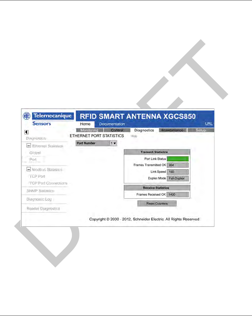
Diagnostics DI[D-SE-0032297.1.3]
130 EIO0000001601 Draft 2013/07/17
Ethernet Port Statistics Page
Ethernet Port Statistics Page
Description
On the left side of the page, under Ethernet Statistics, select Port to open the Ethernet Port
Statistics page.
Use the Ethernet Port Statistics page to:
Display statistical information related to:
transmitted frames,
received frames,
late collisions.
Reset all counting statistics by clicking the Reset Counters button.
The counting statistics on this page are automatically refreshed:
The Ethernet Port Statistics page displays these data fields:
Port Number: Select a port to display its statistics: 1 or 2.
Transmit Statistics
Frames Transmitted OK: A count of frames successfully transmitted.
Duplex Mode: A display of the current duplex mode (full/half).
Link Speed: Displays the current link speed in Mbit/s (10 or 100).
Receive Statistics
Frames Received OK: A count of frames successfully received.
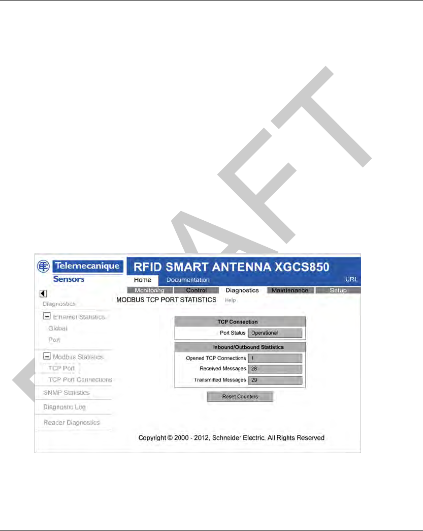
DI[D-SE-0032298.1.4] Diagnostics
EIO0000001601 Draft 2013/07/17 131
Modbus TCP P ort Statistics Pag e
Modbus TCP Port Statistics Page
Description
On the left side of the page, under Modbus Statistics, select TCP Port to open the Modbus TCP
Port Statistics page.
The Modbus TCP Port Statistics page displays data describing the usage of the embedded
Modbus TCP port (port 502).
Use the Modbus TCP Port Statistics page to:
display these data:
Port Status (operational or idle),
a count of each of the following statistics since these counters were last reset (by either a
power cycle or the Reset Counters button):
- Opened TCP Connections
- Received Messages
- Transmitted Messages
access the Reset Counters button, which you can click to clear the counting statistics listed
above.
The statistics on this page are automatically updated:
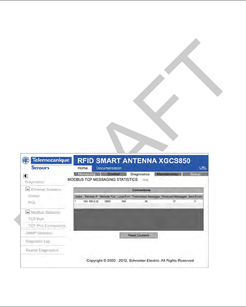
Diagnostics DI[D-SE-0032301.1.3]
132 EIO0000001601 Draft 2013/07/17
Modbus T CP Mess aging Sta tistics Pa ge
Modbus TCP Messaging Statistics Page
Description
On the left side of the page, under Modbus Statistics, select TCP Port Connections to open the
Modbus TCP Messaging Statistics page.
The Modbus TCP Messaging Statistics page displays data describing the usage of the embedded
Modbus TCP Messaging.
Use the Modbus TCP Messaging Statistics page to:
display these data:
Index: the index number,
Remote IP: the IP address of the remote connection,
Remote Port: the port number of the remote connection,
Local Port: the port number of the local connection,
Transmitted Messages: the number of transmitted messages,
Transmitted Messages: the number of received messages,
Sent Errors: the number of detected sent errors.
access the Reset Counters button, which you can click to clear the counting statistics listed
above.
The statistics on this page are automatically updated:
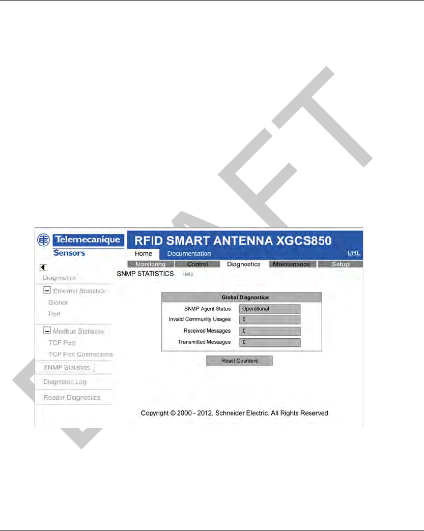
DI[D-SE-0032299.1.3] Diagnostics
EIO0000001601 Draft 2013/07/17 133
SNMP Statistics Page
SNMP Statistics Page
Description
On the left side of the page, select SNMP Statistics to open the SNMP Statistics page.
Use the SNMP Statistics page to:
display the following data describing the Smart Antenna embedded SNMP agent:
SNMP Agent Status: operational or idle,
Bad Community Usages: a count of requests sent to the Smart Antenna containing an
invalid community name, indicating the requesting device may be unauthorized to make such
a request,
Received Messages: a count of the number of SNMP requests received by the Smart
Antenna,
Transmitted Messages: a count of the number of SNMP responses sent by the Smart
Antenna,
reset the 3 counting statistics, above, by clicking the Reset Counters button.
The SNMP Statistics page looks like this:
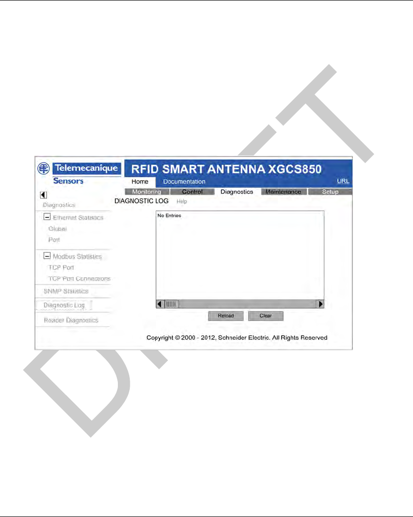
Diagnostics DI[D-SE-0032300.1.3]
134 EIO0000001601 Draft 2013/07/17
Diagnostic Lo g Page
Diagnostic Log Page
Description
On the left side of the page, select Diagnostic Log to open the Diagnostic Log page.
The Diagnostic Log page reports information that is collected during Smart Antenna operations.
In the Diagnostic Log page, you can click the:
Reload button to update the display. This page is not automatically updated, so you can more
easily read its static contents.
Clear button to clear the log. Deleting the log removes its content from flash memory.
The Diagnostic Log page looks like this:
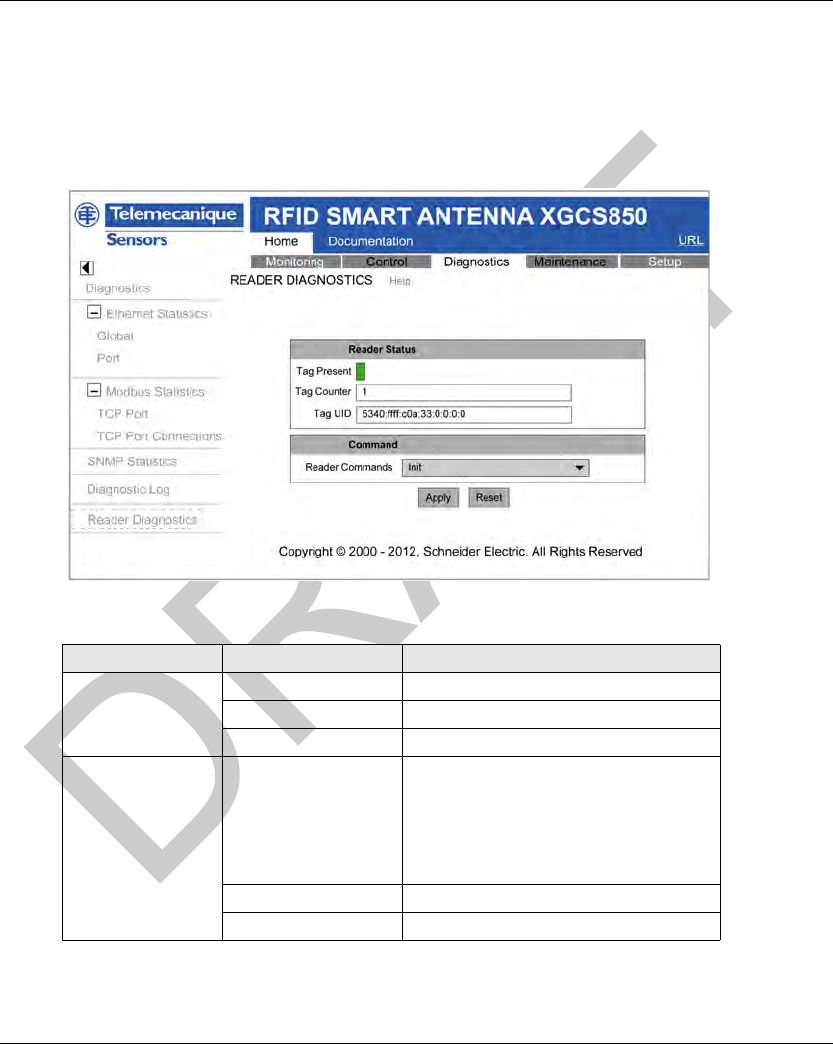
DI[D-SE-0032304.1.3] Diagnostics
EIO0000001601 Draft 2013/07/17 135
Reader Diag nostics P age
Reader Diagnostics Page
Description
On the left side of the page, select Reader Diagnostics to open the Reader Diagnostics page.
The Reader Diagnostics page looks like this:
The table describes the Reader Diagnostics page:
Area Parameter Description
Reader Status Tag Present Green if a tag is present.
Tag Counter Number of detected tags.
Tag UID UID of the last detected tag.
Command Reader Commands Choice of the command to execute
(see page 51):
Init
Reset
Sleep
Execution
Apply Execute the selected command.
Reset Reset the tag counter.

Diagnostics DI[D-SE-0032304.1.3]
136 EIO0000001601 Draft 2013/07/17
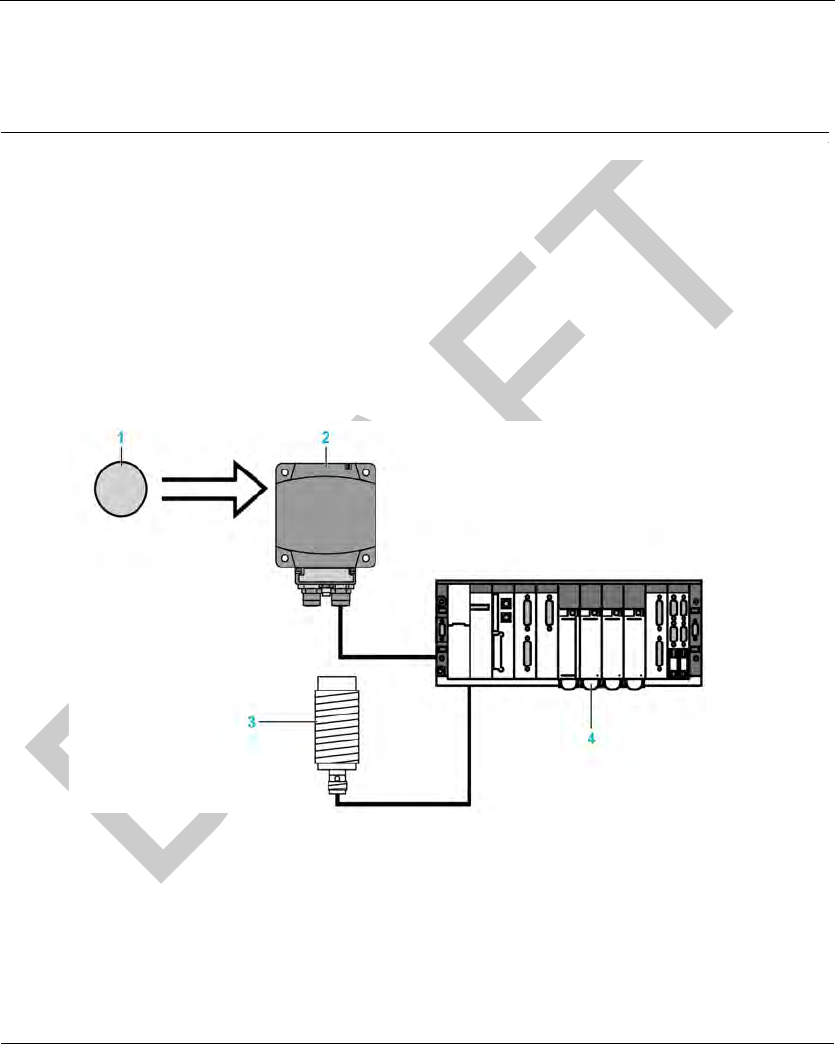
EIO0000001601 Draft 2013/07/17 137
DI[D-SE-0030497.1.2]
RFID OsiSens e® XG
FAQs
EIO0000001601 Draft 2013/07/17
FAQs
Chapter 9
FAQs
FAQs
FAQ
FAQ
Detected Errors During Tag Reading/Writing
How to avoid making errors in reading/writing a tag
To avoid making errors in reading/writing a tag, it is necessary to check the tag presence between
making the request.
1: Use a sensor:
Synchronize the Read/Write requests with a sensor that indicates the presence of the tag to the
control system:
1 Tag
2 Smart Antenna
3 Tag presence sensor
4 PLC
In case of processing detected errors (such as incorrect positioning of the tag or a transmission
detected error), provide for repetition of the request before switching to the "Fallback" mode
(abandoning of the request and generation of an alarm).
2: Read the STATUS word of the Smart Antenna:
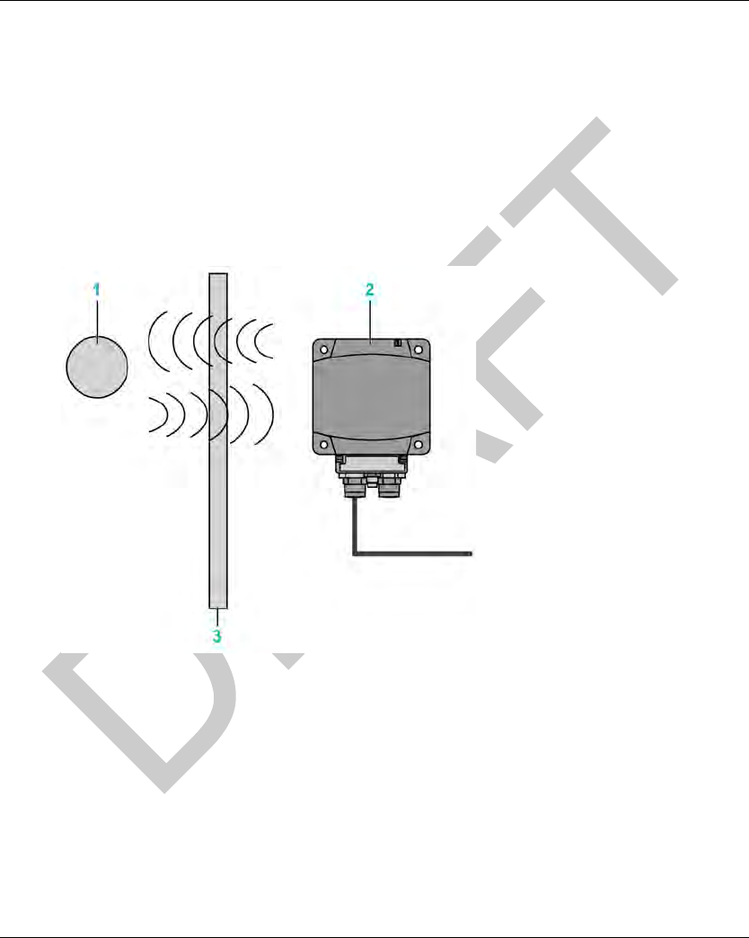
FAQs DI[D-SE-0030496.1.8]
138 EIO0000001601 Draft 2013/07/17
Before initiating a tag Read/Write request, ensure that the tag is present using a request to read
the Smart Antenna STATUS word (bit 0 of the word STATUS = 1 if the tag is present).
Protecting the Smart Antenna
How to protect the Smart Antenna against shock
To protect the system against shock, you can:
Embed the Smart Antenna in metal (seepage36)
Embed the tag in metal (seepage36)
Protect the Smart Antenna by making use of its capability to work through non-metallic materials
according to the diagram shown below:
1 Tag
2 Smart Antenna
3 Non-metallic screen
NOTE: Thermal protection
Avoid exposing the tags to radiating heat sources, such as infrared dryers.
Maximum Cable Length
What is the maximum connection cable length of the Smart Antenna?
100 m (328 ft) between each Smart Antenna.

DI[D-SE-0030496.1.8] FAQs
EIO0000001601 Draft 2013/07/17 139
Line Terminator
How to insert the line terminator?
A line terminator is not necessary on Ethernet network.
COM Detected Error
How to process the communication interruptions between the PLC and the Smart Antenna?
There is a permanent risk of communication detected error in the reading or writing of a tag
(disturbances, EMC, tag in the dialog zone limit...).
It is necessary to integrate the risk management into the PLC program:
Process the detected error codes of the Smart Antenna (request for reading / writing is rejected
since no tag is detected in front of the Smart Antenna,...)
Process the "Time-Out" when the Smart Antenna does not respond, such as "the message is
not included following a disturbance".
In the case of detected error, repeat the request (up to 3 times) before exiting and issuing a PLC
alarm.
Tag Write Number
How many times can it be written in the tags?
The maximum number of writing depends on the tag storage temperature: the higher the
temperature is, the more this limit decreases.
The Smart Antenna tags are provided for at most 100,000 tags per data bit in the defined storage
temperature range.
If the tag is permanently at a temperature less than 30°C /86
°
F (the most frequent case), the
maximum number of typical writings is 2.5 million.
NOTE: For application where frequent writing is required, select a tag with a Feram memory (1010
write cycles).
Readable Data of a Moving Tag
What amount of data can be exchanged in a moving tag?

FAQs DI[D-SE-0030496.1.8]
140 EIO0000001601 Draft 2013/07/17
When the tag is not stopped during its movement in front of the Smart Antenna, it is necessary to:
NOTE: This may generate a tag-writing error or incorrect data writing.
Using third-party Tags
What is the dialog distance between a Smart Antenna and a tag purchased at a third-party
supplier?
There is no normalization of the reading distances. Each tag with its own characteristics cannot
allow a dialog distance.
It is imperative to test a sample to determine the proper dialog distance.
Compatibility of Smart Antenna with other 13.56 MHz Tags
Is my 13.56 MHz tag compatible with the Smart Antenna?
Send a sample to your Schneider agency to verify its compatibility.
Precautions against EMC Perturbations
What are the precautions to be taken regarding EMC?
To avoid EMC perturbations, it is necessary:
Make sure that the Smart Antenna is at least 30 cm (11.81 in) from an EMC source (motor,
solenoid valve, and so on).
Use the intended cables (conceived to protect against EMC perturbations).
Metal Influence
What is the influence of metal on the Smart Antenna/tag reading distances?
The presence of metal near an RFID tag affects the reading distances.
Step Action
1 Determine the speed V of the tag.
2 Determine the number of word to exchange.
4 Refer to the maximum speed in the tag characteristics (see page 25).
NOTICE
UNINTENDED EQUIPMENT OPERATION
Do not make a writing request when the tag exits the detection zone of the Smart Antenna
(Sensing Zone (see page 35)).
Failure to follow these instructions can result in equipment damage.

DI[D-SE-0030496.1.8] FAQs
EIO0000001601 Draft 2013/07/17 141
Some tags in the Smart Antenna range are designed to attenuate this phenomenon (XGHB44••••
and XGHB221346). Other references cannot be attached directly on a metallic support.

FAQs DI[D-SE-0030496.1.8]
142 EIO0000001601 Draft 2013/07/17

EIO0000001601 Draft 2013/07/17 143
RFID OsiSense® XG
Glossary
EIO00000 01601 Draft 2013/07/17
Glossary
Glossary
0-9
100Base-TX
An adaptation of the IEEE 802.3u (Ethernet) standard, the 100Base-T standard uses 2 twisted-pair
wiring with a maximum segment length of 100 m (328 ft) and terminates with an RJ45 connector.
A 100Base-T network is a baseband network capable of transmitting data at a maximum speed of
100 Mbit/s. "Fast Ethernet" is another name for 100Base-T because it is 10 times faster than
10Base-T.
10Base-T
An adaptation of the IEEE 802.3 (Ethernet) standard, the 10Base-T standard uses twisted-pair
wiring with a maximum segment length of 100 m (328 ft) and terminates with an RJ45 connector.
A 10Base-T network is a baseband network capable of transmitting data at a maximum speed of
10 Mbit/s.
802.3 frame
A frame format, specified in the IEEE 802.3 (Ethernet) standard, in which the header specifies the
data packet length.
B
BootP
BootP (bootstrap protocol) is an UDP/IP protocol that allows an Internet node to obtain its IP
parameters based on its MAC address.
C
configuration
The arrangement and interconnection of hardware components within a system and the hardware
and software selections that determine the operating characteristics of the system.
CRC
cyclic redundancy check. Messages that implement this detected error checking mechanism have
a CRC field that is calculated by the transmitter according to the message content. Receiving
nodes recalculate the field. Disagreement in the 2 codes indicates a difference between the
transmitted message and the one received.

Glossary
144 EIO0000001601 Draft 2013/07/17
D
DHCP
dynamic host configuration protocol. A TCP/IP protocol that allows a server to assign an
IP address based on a device name (host name) to a network node.
E
EDS
electronic data sheet. The EDS is a standardized ASCII file that contains information about a
network device communications functionality and the contents of its object dictionary. The EDS
also defines device-specific and manufacturer-specific objects.
EEPROM
Electrically Erasable Programmable Read-Only Memory. EEPROM is a nonvolatile memory.
EMC
electromagnetic compatibility. Devices that meet EMC requirements can operate within a system
expected electromagnetic limits without interruption.
Ethernet
A LAN wiring and signaling specification used to connect devices within a defined area, for
example, a building. Ethernet uses a bus or a star topology to connect different nodes on a
network.
Ethernet II
A frame format in which the header specifies the packet type, Ethernet II is the default frame format
for NIM communications.
EtherNet/IP
EtherNet/IP (the Ethernet Industrial Protocol) is especially suited to factory applications in which
there is a need to control, configure, and monitor events within an industrial system. The ODVA-
specified protocol runs CIP (the Common Industrial Protocol) on top of standard Internet protocols,
like TCP/IP and UDP. It is an open local (communications) network that enables the interconnec-
tivity of all levels of manufacturing operations from the office plant to the sensors and actuators on
its floor.
F
FeRAM
Ferroelectric Random Access Memory. FeRAM is a nonvolatile memory offering faster write
performance and greater number of writing cycles.
flash memory
Flash memory is nonvolatile memory that can be overwritten. It is stored on a special EEPROM
that can be erased and reprogrammed.

Glossary
EIO0000001601 Draft 2013/07/17 145
function block
A function block performs a specific automation function, such as speed control. A function block
comprises configuration data and a set of operating parameters.
function code
A function code is an instruction set commanding 1 or more slave devices at specified addresses
to perform a type of action, for example, read a set of data registers and respond with the content.
H
HMI
human-machine interface. An operator interface, usually graphical, for industrial equipment.
HTTP
hypertext transfer protocol. The protocol that a web server and a client browser use to
communicate with one another.
I
IEC
International Electrotechnical Commission Carrier. Founded in 1884 to focus on advancing the
theory and practice of electrical, electronics, and computer engineering, and computer science.
EN 61131-2 is the specification that deals with industrial automation equipment.
IEEE
Institute of Electrical and Electronics Engineers, Inc. The international standards and conformity
assessment body for all fields of electrotechnology, including electricity and electronics.
IP
Internet Protocol. That part of the TCP/IP protocol family that tracks the Internet addresses of
nodes, routes outgoing messages, and recognizes incoming messages.
IP rating
Ingress Protection rating according to IEC 60529.
L
LAN
local area network. A short-distance data communications network.
LSB
least significant bit, least significant byte. The part of a number, address, or field that is written as
the rightmost single value in conventional hexadecimal or binary notation.

Glossary
146 EIO0000001601 Draft 2013/07/17
M
MAC address
media access control address. A 48-bit number, unique on a network, that is programmed into
each network card or device when it is manufactured.
master/slave model
The direction of control in a network that implements the master/slave model is from the master to
the slave devices.
Modbus
Modbus is an application layer messaging protocol. Modbus provides client and server
communications between devices connected on different types of buses or networks. Modbus
offers many services specified by function codes.
MSB
most significant bit, most significant byte. The part of a number, address, or field that is written as
the leftmost single value in conventional hexadecimal or binary notation.
P
PELV
protective extra low voltage.
PLC
programmable logic controller. The PLC is the brain of an industrial manufacturing process. It
automates a process as opposed to relay control systems. PLCs are computers suited to survive
the harsh conditions of the industrial environment.
R
RFID
radio frequency identification. RFID is a term used for radio frequency identification systems.
These frequencies range between 50 kHz and 2.5 GHz. The most widely used is 13.56 MHz.
Rx
reception.
S
SCADA
supervisory control and data acquisition. Typically accomplished in industrial settings with
microcomputers.
Smart Antenna
RFID reader incorporating all the RFID and network functions in the same device.

Glossary
EIO0000001601 Draft 2013/07/17 147
subnet
A part of a network that shares a network address with the other parts of a network. A subnet may
be physically and/or logically independent of the rest of the network. A part of an Internet address
called a subnet number, which is ignored in IP routing, distinguishes the subnet.
T
TCP
transmission control protocol. A connection-oriented transport layer protocol that provides full-
duplex data transmission. TCP is part of the TCP/IP suite of protocols.
Tx
transmission.
U
UDP
user datagram protocol. A connectionless mode protocol in which messages are delivered in a
datagram to a destination computer. The UDP protocol is typically bundled with the Internet
protocol (UPD/IP).
UID
Unique ID. Identification number of the tag. Each tag has a different UID.

Glossary
148 EIO0000001601 Draft 2013/07/17

EIO0000001601 Draft 2013/07/17 149
RFID OsiS ense® XG
Index
EIO0000001601 Draft 2013/07/17
Index
Index
E
Ethernet
statistics, 103
Ethernet LAN, 103
F
frame type
Ethernet II, 102
IEEE 802.3, 102
I
IP address configuration, 40
IP parameters, 129
M
Modbus function codes, 102
Modbus over TCP/IP
data formats, 102
Modbus protocol, 102
N
network topology, 15
P
PLC, 102
T
TCP/IP statistics, 129
topology, 15
W
web pages
diagnostic log, 134
Ethernet port statistics, 130
Ethernet TCP/IP statistics, 129
SNMP statistics, 133
TCP messaging statistics, 132
TCP port statistics, 131
web server
diagnostic pages, 128
documentation page, 123
Home page, 117
setup page, 41