Schneider Electric France L Isle d Espagnac XGCS85 RFID Reader User Manual Manual Installation Instructions
Schneider Electric Industries France L'Isle d'Espagnac RFID Reader Manual Installation Instructions
Contents
- 1. Manual (Installation Instructions).pdf
- 2. Manual.pdf
Manual (Installation Instructions).pdf
WARNING / AVERTISSEMENT / ADVERTENCIA
en
fr
es
© 2013 Schneider Electric. “All Rights Reserved.”
Electrical equipment should be installed, operated and maintained only by qualified personnel. No responsibility is assumed by Schneider Electric for any
consequences arising out of the use of this material.
Les équipements électriques doivent être installés, exploités et entretenus par un personnel qualifié. Schneider Electric décline toute responsabilité quant aux
conséquences de l’utilisation de ce matériel.
Sólo el personal de servicio cualificado podrá instalar, utilizar, reparar y mantener el equipo eléctrico. Schneider Electric no asume las responsabilidades que pudieran
surgir como consecuencia de la utilización de este material.
Diagnostic LEDs / Voyants de diagnostic / LED de diagnóstico
UNINTENDED EQUIPMENT OPERATION
p Turn off power supplying the Smart Antenna
p This Class B product may cause radio interference.
p The cable routing rules listed in the User Guide of the
EtherNet/IP splitter box must be followed.
p Properly fit all connectors with cables or sealing plugs
and tighten.
p D
o not use factory configured IP address for operation
.
p Do not exceed the maximum number of word to read
or write.
p Consult the User Guide of the EtherNet/IP Smart
Antenna for more detailed informations.
Failure to follow these instructions can result in
death, serious injury, or equipment damage.
FONCTIONNEMENT IMPREVU DE L'EQUIPEMENT
p Couper l'alimentation de la Smart Antenna
p Ce produit de classe B peut générer des interférences
radio.
p Il faut respecter les consignes de cheminement du câble
indiquées dans le manuel utilisateur du répartiteur
EtherNet/IP.
p Équiper correctement tous les connecteurs de câbles ou
de bouchons d'étanchéité et les serrer.
p Ne pas utiliser l'adresse IP configurée en usine lors du
fonctionnement.
p Ne pas dépasser la nombre maximum de mots à lire ou
écrire.
p Consulter le manuel utilisateur de la Smart Antenna
EtherNet/IP pour plus de renseignements.
Le non-respect de ces instructions peut provoquer la
mort, des blessures graves ou des dommages
matériels.
FUNCIONAMIENTO INESPERADO DEL EQUIPO
p Desconecte la alimentación eléctrica de la Smart
Antenna.
p Este producto de clase B puede causar interferencias
de radio.
p Se deben seguir las reglas de cableado enumeradas en
la guía de usuario de la caja de distribución EtherNet/IP.
p Ajuste correctamente todos los conectores con los
cables o tapones de cierre y apriételos.
p No utilice la dirección IP configurada en fábrica para el
funcionamiento.
p No supere el número máximo de palabras de lectura o
escritura.
p Consulte la guía del usuario de la Smart Antenna
EtherNet/IP para obtener más información.
Si no se siguen estas instrucciones pueden
producirse lesiones personales graves o mortales o
daños en el equipo.
www.tesensors.com
XGCS850C201
4/4
HRBxxxxx 00
03 - 2013
en
fr
es
Note: The user guide (N° EIO0000001601) and EDS file are stored in the internal memory and are accessible from the Web server of the XGCS850C201 Smart
Antenna (page “Documentation”). These documents are also accessible on Web site “www.tesensors.com”.
Note : le manuel utilisateur (n° EIO0000001602) et le fichier EDS sont stockés dans la mémoire interne et sont accessibles à partir du serveur Web de la Smart
Antenna XGCS850C201 (page “Documentation”). Ces documents se trouvent également sur le site Web “www.tesensors.com”.
Nota: La guía del usuario (N°EIO0000001603) y el archivo EDS están almacenados en la memoria interna y sepuede acceder a ellos desde el servidor Web de la
Samart Antenna XGCS850C201 (página “Documentation” (Documentación)). También se puede acceder aestos documentos en el sitio web “www.tesensors.com”.
en
fr
es
en
fr es
75
6
93
2
4
1
8
6
7
5
www.tesensors.com
XGCS850C201
1/4
03 - 2013
Printed in
HRBxxxxx 00
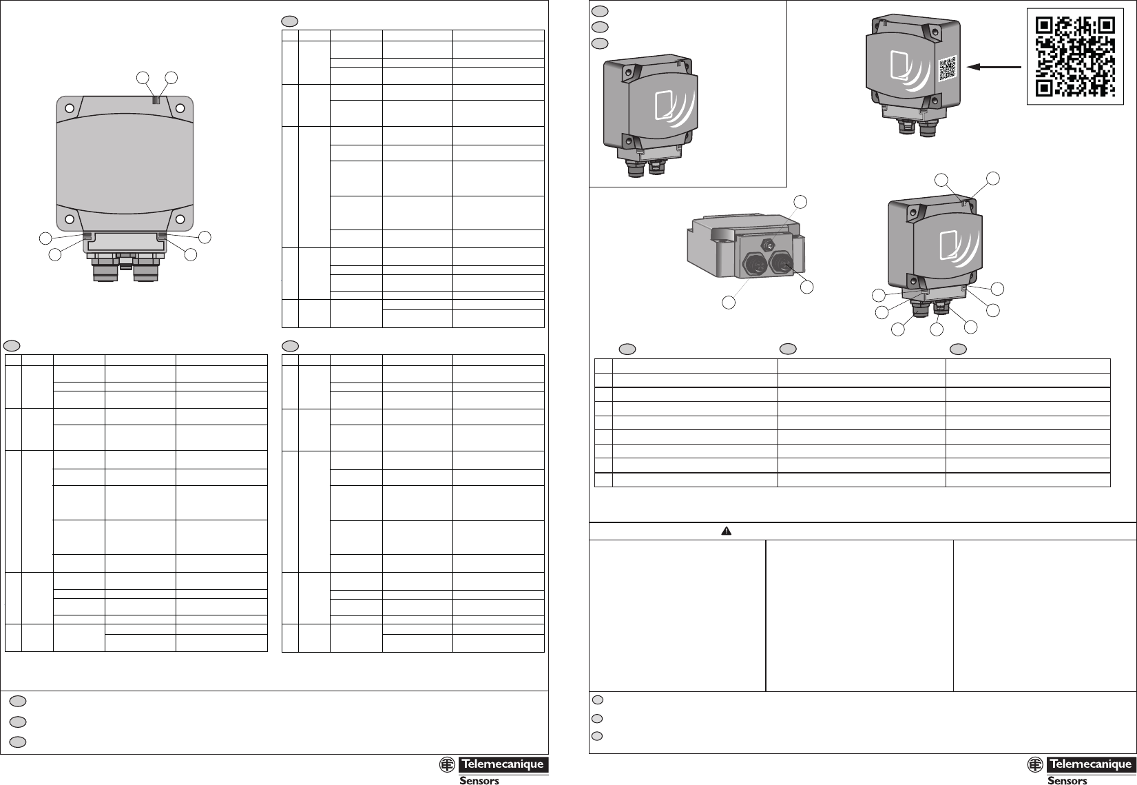
Description / Description / Descripción
EtherNet/IP Smart Antenna
EtherNet/IP Smart Antenna
EtherNet/IP Smart Antenna
en fr es
TAG : Tag LED
M12 socket Ethernet port Nr 1
1
2
3
4
5
6
7
8
9
COM : Communication LED
M8 Socket Power supply 24V
NS : NetworkStatusLED
LK/SP : Ethernet communication port Nr.1 LED
M12 socket Ethernet port Nr 2
LK/SP : Ethernet communcation port Nr.2 LED
MS : Ethernet Module Status LED Setting
TAG : Tag LED
M12 socket Ethernet port Nr 1
COM : Communication LED
M8 Socket Power supply 24V
NS : NetworkStatusLED
LK/SP : Ethernet communication port Nr.1 LED
M12 socket Ethernet port Nr 2
LK/SP : Ethernet communcation port Nr.2 LED
MS : Ethernet Module Status LED Setting
TAG : Tag LED
M12 socket Ethernet port Nr 1
COM : Communication LED
M8 Socket Power supply 24V
NS : NetworkStatusLED
LK/SP : Ethernet communication port Nr.1 LED
M12 socket Ethernet port Nr 2
LK/SP : Ethernet communcation port Nr.2 LED
MS : Ethernet Module Status LED Setting
12
3
48
9
LED Name LED state Description Smart antenna state
Solid Green Tag presence A tag is detected –
dialog ok
1 flash No tag detected Waiting for a tag
Red flashes RFID errors Errors detected in
the dialog with the tag
Green flashes Requests received
from a client
OK
Red flashes Errors in requests
received from a client
Error code returned to
the client (no tag / bad
parameters,..)
Solid Green The network is
operating normally
OK
4 flashes A duplicate IP
condition exists
The smart antenna operates
offline
5 flashes The smart antenna
attempts to get an
IP configuration from
BootP server
The smart antenna sends
BOOTP/DHCP requests to
a BootP server and awaits
a reply
6 flashes Operations are
normal with default
IP adressing settings
BootP requests timed out.
The Smart antenna applied
the default Ip address
(192.168.0.10)
7 flashes Operations are in
kernel mode
The smart antenna attempts
to acquire a new firmware.
Solid Green Ethernet link present
at 100 Mbps
OK
Flashing Green Traffic at 100 Mbps OK
Solid Yellow Ethernet link present
at 10 Mbps
OK
Flashing Yellow Traffic at 10 Mbps OK
OKOn
Off No power supply
Not ready
4
8
9
Link
Activity
(port
1 & 2)
MS
(Ethernet
module)
Green
1
2
3
TAG
COM
NS
(Network
status)
- Link to the user guide and EDS file
- Lien vers le guide d’utilisation et
le fichier EDS
- Enlace a la Guía del usuario y el
archivo EDS
Cette page sert à configurer l'adresse de la EtherNet/IP Smart Antenna :
- Choisir le type d'allocation de l'adresse IP (adressage local ou
automatique par DHCP)
- Saisir l'adresse IP locale, le masque de sous-réseau et l'adresse de
passerelle par défaut
- Confirmer les nouveaux paramètres en cliquant sur le bouton [STORE
CONFIGURATION] (Stocker la configuration)
- Redémarrer la Smart Antenna pour appliquer les nouveaux paramètres
Esta página se utiliza para configurar la dirección de la EtherNet/IP Smart Antenna:
- Opción de asignación de dirección IP (direccionamiento local o automático
con servicio DHCP).
- Entrada de dirección IP local, máscara de subred y dirección
predeterminada de pasarela.
- Confirme los nuevos parámetros haciendo clic en el botón [STORE
CONFIGURATION] (Almacenar configuración).
- Apague y vuelva a encender la Smart Antenna para aplicar los nuevos
parámetros.
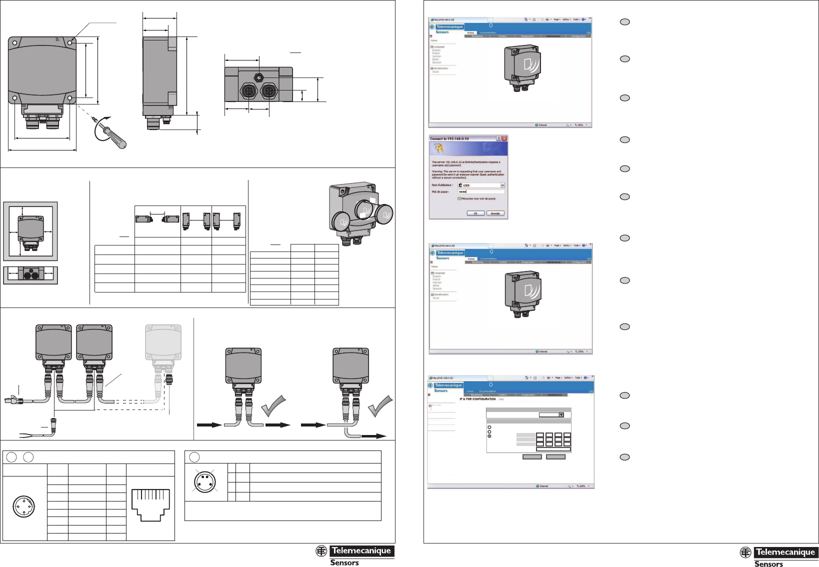
This page is used to configure the EtherNet/IP Smart Antenna address:
- Choice of IP address allocation (local or automatic addressing with
DHCP service)
- Entry of the local IP address, subnet mask, and default gateway address
- Confirm the new parameters by a click on [STORE CONFIGURATION]
button
- Cycle the power of the Smart Antenna to apply the new parameters
mm
in.
www.tesensors.com
XGCS850C201
2/4
Address configuration
/ Configuration de l'adresse / Configuración de la dirección
- Home page / Page d'accueil / Página de inicio :
- Setup page / Page de configuration / Página de configuración :
en
fr
es
en
fr
es
en
fr
es
en
fr
es
03 - 2013
HRBxxxxx 00
03 - 2013
HRBxxxxx 00
www.tesensors.com
XGCS850C201
3/4
PELV Power supply - The 0 V must be connected to the earth to increase EMC strength.
Alimentation TBTS - Le 0 V doit être relié à la terre pour améliorer la CEM.
Alimentación eléctrica PELV - Los 0 V se deben conectar a tierra para mejorar la CEM.
Connectors wiring
/ Câblage des connecteurs / Cableado de conectores
1
3
2
4
–
–
–
–
TD+
TD-
RD+
RD-
Not connected
Not connected
Not connected
Not connected
4
1
2
3
5 7
38 7 6 5 4 2 1
612345 78
M12 - 4 pins
Connector
M12
Contact Signal RJ45
Contact
1
2
3
6
4
5
7
8
RJ45
Connector
c + 24 V
Not connected
c 0 V
Not connected
13
24 1 BN
2 WH
3 BU
4 BK
6
65
2.56
80
3.15
A
A: 3,6 Nm / 31.9 lbf.in
30
1.18
1.57
40
1.57
40
27,5
1.08
25
0.98
11,5
0.45
28
1.1
93
3.66
15
0.59
65
2.56
80
3.15
4 x Ø 5,5
4 x Ø 0.217
Dimensions / Encombrements / Dimensiones
Wiring Diagrams / Schémas de câblage / Esquemas de cableado
Utilization precautions / Précautions de mise en oeuvre / Precauciones de instalación
XGSZp2E45pp
XZCP0941Lp
XGSZ12E12pp
ASI67FACC1(*)
EtherNet/IP
2n
1
(Ethernet M12 D coded - 5 pins socket) (M8 - 4 pins male socket)
e >20 mm
e >0.787in.
mm
in. mm
in.
M12 connectors: Maximum tightening
torque = 1.5 N.m (13.3 lb-in)
Connecteurs M12 : Couple de serrage maximal
= 1,5 N.m (13.3 lb-in)
Conectores M12: Par de apriete máximo
= 1,5 N.m (13.3 lb-in)
M8 connectors: Maximum tightening
torque = 0.5 N.m (4.4 lb-in)
Connecteurs M8 : Couple de serrage maximal
= 0,5 N.m (4.4 lb-in)
Conectores M8: Par de apriete máximo
= 0,5 N.m (4.4 lb-in)
e3 e4
e1 ue2 ue3 u
e1
XGHB90E340
XGHB221346
XGHB320ppp
XGHB211345
XGHB44ppp
430/6.93 750/29.53 280/11.02
280/11.02 530/20.87 260/10.24
310/12.2 540/21.26 240/9.45
200/7.87 370/14.57 170/6.69
310/12.2 400/15.75 160/6.3
d1ud2 u
110/4.33 140/5.51
120/4.72 50/1.97
190/7.48 60/2.36
120/4.72 20/0.79
70/2.76 40/1.57
60/2.36 10/0.39
60/2.36 10/0.39
60/2.36 10/0.39
XGHB90E340
XGHB221346
XGHB320345
XGHB211345
XGHB444345
XGHB445345
XGHB440845
XGHB443245
IP address setup by the Web server:
The XGCS850C201 Smart Antenna includes a Web server.
The factory setting for the IP address of the XGCS850C201 is: 192.168.0.10
Connection to the Web server Home page
Configure the computer IP address with an address which is compatible with
the Smart Antenna (example: Smart Antenna = 192.168.0.10 V PC = 192.168.0.1)
From your PC browser, enter the following address: http://192.168.0.10/
Configuration de l'adresse IP par le serveur Web :
La Smart Antenna XGCS850C201 comprend un serveur Web.
Le réglage usine de l'adresse IP du XGCS850C201 est : 192.168.0.10
Connexion à la page d'accueil du serveur Web
Configurer l'adresse IP de l'ordinateur avec une adresse compatible à
celle de la Smart Antenna
(exemple : Smart Antenna = 192.168.0.10 V PC = 192.168.0.1)
Configuración de dirección IP mediante el servidor web:
La Smart Antenna XGCS850C201 incluye un servidor Web.
El ajuste de fábrica de la dirección IP de la XGCS850C201 es: 192.168.0.10
Conexión con la página de inicio del servidor Web
Configure la dirección IP del ordenador con una dirección que sea compatible
con la Smart Antenna (ejemplo: Smart Antenna = 192.168.0.10 V PC = 192.168.0.1)
En el explorador del PC, introduzca la siguiente dirección: http://192.168.0.10/
OsiSense
R
XG RFiD - EtherNet/IP Smart Antenna - XGCS850C201
Web site version : 2.0.2
Copyright © 2000 - 2012, Schneider Electric. All Rights Reserved
OsiSense
R
XG RFiD - EtherNet/IP Smart Antenna - XGCS850C201
Web site version : 2.0.2
Copyright © 2000 - 2012, Schneider Electric. All Rights Reserved
IP address:
Subnet mask:
Default Gateway:
Device Name:
IP Parameters
Apply Undo
192
255
192
168
255
168
0
255 0
0
10
1
.
.
.
.
.
.
.
.
.
DHCP Client
Automatic (BootP)
Local (Stored IP)
Ethernet Frame Format
Ethernet Parameters
Ethernet II
Configuration
IP & FDR Client
Security
HTTP User Admin
Ethernet Ports
SNMP Agent
Configuration
Web site version : 2.0.2
Copyright © 2000 - 2012, Schneider Electric. All Rights Reserved
OsiSense
R
XG RFiD - EtherNet/IP Smart Antenna - XGCS850C201
Security:
User name and passwordare requested to secure the access to the web server.
The factory settings are :
User name= USER
Password= USER
Security:
User name and passwordare requested to secure the access to the web server.
The factory settings are :
User name= USER
Password= USER
Security:
User name and passwordare requested to secure the access to the web server.
The factory settings are :
User name= USER
Password= USER
Select [Configuration] in the menu of the home page
and then, [IP & FDR Client] in the left side of the page
Modifications in this page are applied after a power cycling of the Smart Antenna
Select [Configuration] in the menu of the home page
and then, [IP & FDR Client] in the left side of the page
Modifications in this page are applied after a power cycling of the Smart Antenna
Select [Configuration] in the menu of the home page
and then, [IP & FDR Client] in the left side of the page
Modifications in this page are applied after a power cycling of the Smart Antenna
ee
e
d
e e
d: depending on the connector size
d: en fonction de la taille du connecteur
d: dependiendo del tamaño del conector
Mounting on a metal structure
Montage sur une structure métallique
Montaje sobre una estructura de metal
Distance between two Smart Antennas according to the used tag
Distance entre deux Smart Antenna en fonction de l’étiquette utilisée
Distancia entre dos Smart Antenna de acuerdo con la etiqueta utilizada
Distance between tags
Distance entre étiquettes
Distancia entre las etiquetas
(*): delivered with the Smart Antenna
Livré avec la Smart Antenna
Suministrado con la Smart Antenna
d1
d2