Schneider Electric France L Isle d Espagnac ZARB ZARB BASE use a Bluetooth module User Manual USERS MANUAL
Schneider Electric Industries France L'Isle d'Espagnac ZARB BASE use a Bluetooth module USERS MANUAL
USERS MANUAL

EIO0000001505.00
www.schneider-electric.com
Harmony eXLhoist
EIO0000001505 04/2014
Harmony eXLhoist
Wireless Remote Control System
User Guide
04/2014

2EIO0000001505 04/2014
The information provided in this documentation contains general descriptions and/or technical
characteristics of the performance of the products contained herein. This documentation is not
intended as a substitute for and is not to be used for determining suitability or reliability of these
products for specific user applications. It is the duty of any such user or integrator to perform the
appropriate and complete risk analysis, evaluation and testing of the products with respect to the
relevant specific application or use thereof. Neither Schneider Electric nor any of its affiliates or
subsidiaries shall be responsible or liable for misuse of the information contained herein. If you
have any suggestions for improvements or amendments or have found errors in this publication,
please notify us.
No part of this document may be reproduced in any form or by any means, electronic or
mechanical, including photocopying, without express written permission of Schneider Electric.
All pertinent state, regional, and local safety regulations must be observed when installing and
using this product. For reasons of safety and to help ensure compliance with documented system
data, only the manufacturer should perform repairs to components.
When devices are used for applications with technical safety requirements, the relevant
instructions must be followed.
Failure to use Schneider Electric software or approved software with our hardware products may
result in injury, harm, or improper operating results.
Failure to observe this information can result in injury or equipment damage.
© 2014 Schneider Electric. All rights reserved.

EIO0000001505 04/2014 3
Table of Contents
Safety Information . . . . . . . . . . . . . . . . . . . . . . . . . . . . . 7
About the Book. . . . . . . . . . . . . . . . . . . . . . . . . . . . . . . . 9
Chapter 1 Wireless Remote Control System. . . . . . . . . . . . . . . . . 13
Wireless Remote Control System Overview . . . . . . . . . . . . . . . . . . . . 14
Package Contents . . . . . . . . . . . . . . . . . . . . . . . . . . . . . . . . . . . . . . . . 19
Parts Identification and Main Features . . . . . . . . . . . . . . . . . . . . . . . . 20
Certifications and Standards . . . . . . . . . . . . . . . . . . . . . . . . . . . . . . . . 29
Accessories . . . . . . . . . . . . . . . . . . . . . . . . . . . . . . . . . . . . . . . . . . . . . 33
Chapter 2 Specifications . . . . . . . . . . . . . . . . . . . . . . . . . . . . . . . . . 35
2.1 Base Station Specifications . . . . . . . . . . . . . . . . . . . . . . . . . . . . . . . . . 36
Base Station Specifications . . . . . . . . . . . . . . . . . . . . . . . . . . . . . . . . . 37
RADIO Specification . . . . . . . . . . . . . . . . . . . . . . . . . . . . . . . . . . . . . . 43
2.2 Remote Device Specifications. . . . . . . . . . . . . . . . . . . . . . . . . . . . . . . 46
Remote Device Specifications. . . . . . . . . . . . . . . . . . . . . . . . . . . . . . . 47
Remote Device Charger Specification. . . . . . . . . . . . . . . . . . . . . . . . . 48
2.3 Dimensions . . . . . . . . . . . . . . . . . . . . . . . . . . . . . . . . . . . . . . . . . . . . . 49
Base Station Dimensions . . . . . . . . . . . . . . . . . . . . . . . . . . . . . . . . . . 50
Remote Device Dimensions . . . . . . . . . . . . . . . . . . . . . . . . . . . . . . . . 51
Chapter 3 Safety. . . . . . . . . . . . . . . . . . . . . . . . . . . . . . . . . . . . . . . . 53
3.1 Generalities . . . . . . . . . . . . . . . . . . . . . . . . . . . . . . . . . . . . . . . . . . . . . 54
Introduction . . . . . . . . . . . . . . . . . . . . . . . . . . . . . . . . . . . . . . . . . . . . . 55
Standards and Terminology . . . . . . . . . . . . . . . . . . . . . . . . . . . . . . . . 56
Basics . . . . . . . . . . . . . . . . . . . . . . . . . . . . . . . . . . . . . . . . . . . . . . . . . 57
3.2 Description and Safety Function Capability. . . . . . . . . . . . . . . . . . . . . 61
Wireless Remote Control System Safety Functions Are Part of an
Overall System . . . . . . . . . . . . . . . . . . . . . . . . . . . . . . . . . . . . . . . . . . 62
Getting and Operating the Safety Function . . . . . . . . . . . . . . . . . . . . . 63
E-STOP . . . . . . . . . . . . . . . . . . . . . . . . . . . . . . . . . . . . . . . . . . . . . . . . 64
STOP Function . . . . . . . . . . . . . . . . . . . . . . . . . . . . . . . . . . . . . . . . . . 65
Standard Motion & Auxiliary Functions . . . . . . . . . . . . . . . . . . . . . . . . 66
Safeguarding . . . . . . . . . . . . . . . . . . . . . . . . . . . . . . . . . . . . . . . . . . . . 67
Priority of Safety Functions . . . . . . . . . . . . . . . . . . . . . . . . . . . . . . . . . 68

4EIO0000001505 04/2014
Safe State of the Wireless Remote Control System . . . . . . . . . . . . . . 69
Response Time and Process Safety Time (PST) . . . . . . . . . . . . . . . . 70
Legal RFU (Recommendation for Use) . . . . . . . . . . . . . . . . . . . . . . . . 71
Summary of the Reliability Study . . . . . . . . . . . . . . . . . . . . . . . . . . . . . 72
3.3 Functional Safety Function Commissioning . . . . . . . . . . . . . . . . . . . . . 73
Safety Parameters and Steps to Configure the Safety Functions . . . . 74
Machine Signature . . . . . . . . . . . . . . . . . . . . . . . . . . . . . . . . . . . . . . . . 75
3.4 Functional Safety Requirements for Maintenance . . . . . . . . . . . . . . . . 77
Maintenance. . . . . . . . . . . . . . . . . . . . . . . . . . . . . . . . . . . . . . . . . . . . . 78
Base Station or Remote Device Replacement. . . . . . . . . . . . . . . . . . . 79
Changing Machine Equipment . . . . . . . . . . . . . . . . . . . . . . . . . . . . . . . 80
Chapter 4 Installation and Wiring. . . . . . . . . . . . . . . . . . . . . . . . . . 81
4.1 Base Station Installation. . . . . . . . . . . . . . . . . . . . . . . . . . . . . . . . . . . . 82
Base Station Installation Precaution . . . . . . . . . . . . . . . . . . . . . . . . . . 82
4.2 Base Station Wiring . . . . . . . . . . . . . . . . . . . . . . . . . . . . . . . . . . . . . . . 86
Base Station Wiring . . . . . . . . . . . . . . . . . . . . . . . . . . . . . . . . . . . . . . . 87
Wiring Best Practices. . . . . . . . . . . . . . . . . . . . . . . . . . . . . . . . . . . . . . 91
Factory Setting Description . . . . . . . . . . . . . . . . . . . . . . . . . . . . . . . . . 94
4.3 Functionalities Description . . . . . . . . . . . . . . . . . . . . . . . . . . . . . . . . . . 98
Motion/Auxiliary Relays . . . . . . . . . . . . . . . . . . . . . . . . . . . . . . . . . . . . 99
Selector . . . . . . . . . . . . . . . . . . . . . . . . . . . . . . . . . . . . . . . . . . . . . . . . 102
Detected Applicative Alarm . . . . . . . . . . . . . . . . . . . . . . . . . . . . . . . . . 103
Unintended Operating Control (UOC) Function . . . . . . . . . . . . . . . . . . 105
Safeguarding Function. . . . . . . . . . . . . . . . . . . . . . . . . . . . . . . . . . . . . 107
Special Functions. . . . . . . . . . . . . . . . . . . . . . . . . . . . . . . . . . . . . . . . . 109
Safety Relay. . . . . . . . . . . . . . . . . . . . . . . . . . . . . . . . . . . . . . . . . . . . . 111
4.4 Remote Device Installation . . . . . . . . . . . . . . . . . . . . . . . . . . . . . . . . . 112
Customize The Remote Device . . . . . . . . . . . . . . . . . . . . . . . . . . . . . . 113
First Commissioning. . . . . . . . . . . . . . . . . . . . . . . . . . . . . . . . . . . . . . . 114
Chapter 5 Using The Wireless Remote Control System . . . . . . . 117
5.1 Basic Uses . . . . . . . . . . . . . . . . . . . . . . . . . . . . . . . . . . . . . . . . . . . . . . 118
Main Modes Diagram. . . . . . . . . . . . . . . . . . . . . . . . . . . . . . . . . . . . . . 119
Power ON. . . . . . . . . . . . . . . . . . . . . . . . . . . . . . . . . . . . . . . . . . . . . . . 120
E-STOP . . . . . . . . . . . . . . . . . . . . . . . . . . . . . . . . . . . . . . . . . . . . . . . . 121
STOP . . . . . . . . . . . . . . . . . . . . . . . . . . . . . . . . . . . . . . . . . . . . . . . . . . 123
START . . . . . . . . . . . . . . . . . . . . . . . . . . . . . . . . . . . . . . . . . . . . . . . . . 125
Power OFF. . . . . . . . . . . . . . . . . . . . . . . . . . . . . . . . . . . . . . . . . . . . . . 128

EIO0000001505 04/2014 5
5.2 Functionalities . . . . . . . . . . . . . . . . . . . . . . . . . . . . . . . . . . . . . . . . . . . 130
Standard Motion . . . . . . . . . . . . . . . . . . . . . . . . . . . . . . . . . . . . . . . . . 131
Auxiliary Function . . . . . . . . . . . . . . . . . . . . . . . . . . . . . . . . . . . . . . . . 133
Selector . . . . . . . . . . . . . . . . . . . . . . . . . . . . . . . . . . . . . . . . . . . . . . . . 134
Horn. . . . . . . . . . . . . . . . . . . . . . . . . . . . . . . . . . . . . . . . . . . . . . . . . . . 136
5.3 Discovering . . . . . . . . . . . . . . . . . . . . . . . . . . . . . . . . . . . . . . . . . . . . . 137
Discovering . . . . . . . . . . . . . . . . . . . . . . . . . . . . . . . . . . . . . . . . . . . . . 137
5.4 How to Modify the Configuration . . . . . . . . . . . . . . . . . . . . . . . . . . . . . 140
How to Modify a Configuration . . . . . . . . . . . . . . . . . . . . . . . . . . . . . . 140
5.5 Remote Device Charge . . . . . . . . . . . . . . . . . . . . . . . . . . . . . . . . . . . . 143
Remote Device Charge . . . . . . . . . . . . . . . . . . . . . . . . . . . . . . . . . . . . 143
Chapter 6 Diagnostic . . . . . . . . . . . . . . . . . . . . . . . . . . . . . . . . . . . . 147
6.1 Base Station Diagnostic . . . . . . . . . . . . . . . . . . . . . . . . . . . . . . . . . . . 148
Diagnostic . . . . . . . . . . . . . . . . . . . . . . . . . . . . . . . . . . . . . . . . . . . . . . 148
6.2 ZART•D Diagnostic . . . . . . . . . . . . . . . . . . . . . . . . . . . . . . . . . . . . . . . 149
Diagnostic Mode . . . . . . . . . . . . . . . . . . . . . . . . . . . . . . . . . . . . . . . . . 150
Radio Communication Indicator . . . . . . . . . . . . . . . . . . . . . . . . . . . . . 152
Battery Level of the Remote Device . . . . . . . . . . . . . . . . . . . . . . . . . . 153
E-STOP LED . . . . . . . . . . . . . . . . . . . . . . . . . . . . . . . . . . . . . . . . . . . . 154
Applicative Alarms Signals . . . . . . . . . . . . . . . . . . . . . . . . . . . . . . . . . 155
Detected Failure Displays . . . . . . . . . . . . . . . . . . . . . . . . . . . . . . . . . . 156
6.3 ZART8L Diagnostic . . . . . . . . . . . . . . . . . . . . . . . . . . . . . . . . . . . . . . . 157
ZART8L LED Diagnostic . . . . . . . . . . . . . . . . . . . . . . . . . . . . . . . . . . . 157
Chapter 7 eXLhoist Configuration Software . . . . . . . . . . . . . . . . . 161
7.1 Introduction to eXLhoist Configuration Software . . . . . . . . . . . . . . . . . 162
What is eXLhoist Configuration Software? . . . . . . . . . . . . . . . . . . . . . 163
Connect a Remote Device to the PC. . . . . . . . . . . . . . . . . . . . . . . . . . 165
Installation . . . . . . . . . . . . . . . . . . . . . . . . . . . . . . . . . . . . . . . . . . . . . . 167
7.2 User Interface . . . . . . . . . . . . . . . . . . . . . . . . . . . . . . . . . . . . . . . . . . . 168
Starting Screen . . . . . . . . . . . . . . . . . . . . . . . . . . . . . . . . . . . . . . . . . . 169
Main Window . . . . . . . . . . . . . . . . . . . . . . . . . . . . . . . . . . . . . . . . . . . . 170
Status Bar . . . . . . . . . . . . . . . . . . . . . . . . . . . . . . . . . . . . . . . . . . . . . . 171
Toolbar . . . . . . . . . . . . . . . . . . . . . . . . . . . . . . . . . . . . . . . . . . . . . . . . 172
Menu Bar . . . . . . . . . . . . . . . . . . . . . . . . . . . . . . . . . . . . . . . . . . . . . . . 173
Workspace. . . . . . . . . . . . . . . . . . . . . . . . . . . . . . . . . . . . . . . . . . . . . . 174

6EIO0000001505 04/2014
7.3 Project Management . . . . . . . . . . . . . . . . . . . . . . . . . . . . . . . . . . . . . . 175
Diagram . . . . . . . . . . . . . . . . . . . . . . . . . . . . . . . . . . . . . . . . . . . . . . . . 176
Starting and Exiting eXLhoist Configuration Software . . . . . . . . . . . . . 178
Creating a Project . . . . . . . . . . . . . . . . . . . . . . . . . . . . . . . . . . . . . . . . 179
Edit a Connection. . . . . . . . . . . . . . . . . . . . . . . . . . . . . . . . . . . . . . . . . 182
Project Passwords Management . . . . . . . . . . . . . . . . . . . . . . . . . . . . . 183
Load the Configuration into the Remote Device . . . . . . . . . . . . . . . . . 185
Save a Project . . . . . . . . . . . . . . . . . . . . . . . . . . . . . . . . . . . . . . . . . . . 186
Export to PDF. . . . . . . . . . . . . . . . . . . . . . . . . . . . . . . . . . . . . . . . . . . . 187
7.4 Configuration . . . . . . . . . . . . . . . . . . . . . . . . . . . . . . . . . . . . . . . . . . . . 188
Device Identity . . . . . . . . . . . . . . . . . . . . . . . . . . . . . . . . . . . . . . . . . . . 189
Parameters. . . . . . . . . . . . . . . . . . . . . . . . . . . . . . . . . . . . . . . . . . . . . . 191
Relay Assignment . . . . . . . . . . . . . . . . . . . . . . . . . . . . . . . . . . . . . . . . 194
Interlocking. . . . . . . . . . . . . . . . . . . . . . . . . . . . . . . . . . . . . . . . . . . . . . 198
Detected Applicative Alarms . . . . . . . . . . . . . . . . . . . . . . . . . . . . . . . . 199
Chapter 8 Maintenance / Device Replacement . . . . . . . . . . . . . . . 201
8.1 Maintenance. . . . . . . . . . . . . . . . . . . . . . . . . . . . . . . . . . . . . . . . . . . . . 202
Regular Cleaning . . . . . . . . . . . . . . . . . . . . . . . . . . . . . . . . . . . . . . . . . 202
8.2 Device Replacement . . . . . . . . . . . . . . . . . . . . . . . . . . . . . . . . . . . . . . 203
Base Station Replacement. . . . . . . . . . . . . . . . . . . . . . . . . . . . . . . . . . 204
ZART•D Replacement . . . . . . . . . . . . . . . . . . . . . . . . . . . . . . . . . . . . . 207
ZART8L Device Replacement . . . . . . . . . . . . . . . . . . . . . . . . . . . . . . . 210
8.3 Remote Device Resets . . . . . . . . . . . . . . . . . . . . . . . . . . . . . . . . . . . . 211
Remote Device Resets . . . . . . . . . . . . . . . . . . . . . . . . . . . . . . . . . . . . 211
Appendices . . . . . . . . . . . . . . . . . . . . . . . . . . . . . . . . . . . . . . . . . 213
Appendix A Architecture Examples . . . . . . . . . . . . . . . . . . . . . . . . . 215
Tested Architectures . . . . . . . . . . . . . . . . . . . . . . . . . . . . . . . . . . . . . . 216
Vacuum/Magnetic Application Example . . . . . . . . . . . . . . . . . . . . . . . 221
Room Lighting Application Example . . . . . . . . . . . . . . . . . . . . . . . . . . 224
Glossary . . . . . . . . . . . . . . . . . . . . . . . . . . . . . . . . . . . . . . . . . 225
EIO0000001505 04/2014 7
Safety Information
Important Information
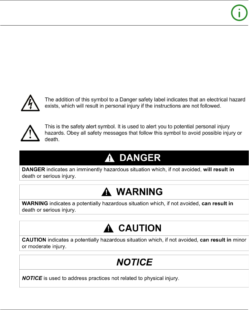
NOTICE
Read these instructions carefully, and look at the equipment to become familiar with the device
before trying to install, operate, or maintain it. The following special messages may appear
throughout this documentation or on the equipment to warn of potential hazards or to call attention
to information that clarifies or simplifies a procedure.

8EIO0000001505 04/2014
PLEASE NOTE
Electrical equipment should be installed, operated, serviced, and maintained only by qualified
personnel. No responsibility is assumed by Schneider Electric for any consequences arising out of
the use of this material.
A qualified person is one who has skills and knowledge related to the construction and operation
of electrical equipment and its installation, and has received safety training to recognize and avoid
the hazards involved.

EIO0000001505 04/2014 9
About the Book
At a Glance
Document Scope
This manuel describes how to use the Wireless Remote Control System.
Validity Note
The technical characteristics of the devices described in this document also appear online. To
access this information online:
The characteristics that are presented in this manual should be the same as those characteristics
that appear online. In line with our policy of constant improvement, we may revise content over time
to improve clarity and accuracy. If you see a difference between the manual and online information,
use the online information as your reference.
Related Documents
Step Action
1 Go to the Schneider Electric home page www.schneider-electric.com.
2 In the Search box type the reference of a product or the name of a product range.
Do not include blank spaces in the model number/product range.
To get information on grouping similar modules, use asterisks (*).
3 If you entered a reference, go to the Product datasheets search results and click on the
reference that interests you.
If you entered the name of a product range, go to the Product Ranges search results and click
on the product range that interests you.
4 If more than one reference appears in the Products search results, click on the reference that
interests you.
5 Depending on the size of your screen, you may need to scroll down to see the data sheet.
6 To save or print a data sheet as a .pdf file, click Download XXX product datasheet.
Title of Documentation Reference Number
Instruction Sheet System XARS8L HRB57247
Instruction Sheet System XARS•D HRB57248
Instruction Sheet Accessory Charger HRB57251
Instruction Sheet Accessory Soft & Cables HRB57273
Instruction Sheet Accessory Shoulder Harness HRB57274
10 EIO0000001505 04/2014
You can download these technical publications and other technical information from our website
at www.schneider-electric.com.
Product Related Information
Instruction Sheet Accessory Remote Holder HRB57277
Instruction Sheet Accessory Rubber Protection EAV52994
Instruction Sheet Accessory Pad & Trigger EAV52985
Instruction Sheet Accessory External Antenna EAV59906
Title of Documentation Reference Number
DANGER
HAZARD OF ELECTRIC SHOCK, EXPLOSION OR ARC FLASH
Disconnect all power from all equipment including connected devices prior to removing any
covers or doors, or installing or removing any accessories, hardware, cables, connectors or
wires except under the specific conditions specified in this user guide.
Always use a properly rated voltage sensing device to confirm that the power is off.
Unplug the power cable from both the equipment and the power supply.
Replace and secure all covers, accessories, hardware, cables, and wires and confirm that a
proper ground connection exists before applying power to the equipment.
Use only the specified voltage when operating this equipment and any associated products.
Failure to follow these instructions will result in death or serious injury.
WARNING
UNINTENDED EQUIPMENT OPERATION
Do not open the Remote Device.
Do not replace internal parts of the Base Station.
After a Base Station power off, wait until the STATUS LED becomes OFF (around 20 seconds)
before removing the cover.
Always comply with the local requirements regarding installation and use of the hoisting
devices.
Failure to follow these instructions can result in death, serious injury, or equipment
damage.
EIO0000001505 04/2014 11
Battery Warning Notes
Carefully read all instructions in this user guide, and look at the equipment to become familiar with
the device before trying to install, operate, or maintain it.
For more information, contact us at www.schneider-electric.com or contact your local reseller.
WARNING
UNINTENDED EQUIPMENT OPERATION
Only use software approved by Schneider Electric for use with this equipment.
Update your application program every time you change the hardware configuration.
Failure to follow these instructions can result in death, serious injury, or equipment
damage.
NOTE:
To increase the system security, it is recommended to use Configuration File transfer password.
WARNING
EXPLOSION, FIRE, OR CHEMICAL HAZARD
Electric devices that have reached the end of their life must be collected separately and
returned to an environmentally compatible recycling facility in accordance with national law.
In case of electrolyte leak from battery, use adapted safety equipment and put the device in a
sealed package.
If you come into contact with electrolyte, immediately thoroughly wash the involved parts with
clear water and call medical assistance.
Do not incinerate the device.
Do not drop or hit the device.
Do not use a damaged device.
The Remote Device battery is a 1Ah LiFePO4 battery. Do not replace it by yourself. In case of
Remote Device battery malfunction or for any maintenance, contact us at www.schneider-
electric.com or contact your local reseller.
Failure to follow these instructions can result in death, serious injury, or equipment
damage.
NOTE: Advice to improve battery life:
Charge the battery before device requires it.
Charge the battery with room temperature within 10…40 °C (50…104 °F).
Charge the battery once in every six months if you do not use it for a long time.

12 EIO0000001505 04/2014

EIO0000001505 04/2014 13
Harmony eXLhoist
Wireless Re mote Control System
EIO0000001505 04/2014
Wireless Re mote Control System
Chapter 1
Wireless Remote Control System
What Is in This Chapter?
This chapter contains the following topics:
Topic Page
Wireless Remote Control System Overview 14
Package Contents 19
Parts Identification and Main Features 20
Certifications and Standards 29
Accessories 33

Wireless Remote Control System
14 EIO0000001505 04/2014
Wireless Remote Control System Overview
Overview
The Harmony™ eXLhoist range of wireless remote control systems is an operator control station
used in hoisting and material handling applications.
The Wireless Remote Control System is based on 2 types of devices:
Remote Device (or transmitter), which is the operator command device to interface with the
machine.
Base Station (or receiver), which is hardwired to the machine. It receives control commands
from the Remote Device and transmits information to the operator.
The Wireless Remote Control System is a combination of these devices which communicate by
radio transmission.
Radio Communication
Each Base Station have a unique ID managed by Schneider Electric. It permits up to 50 single
systems working at same time without perturbation in a 100 x 100 meter area.
Wireless Remote Control System
EIO0000001505 04/2014 15
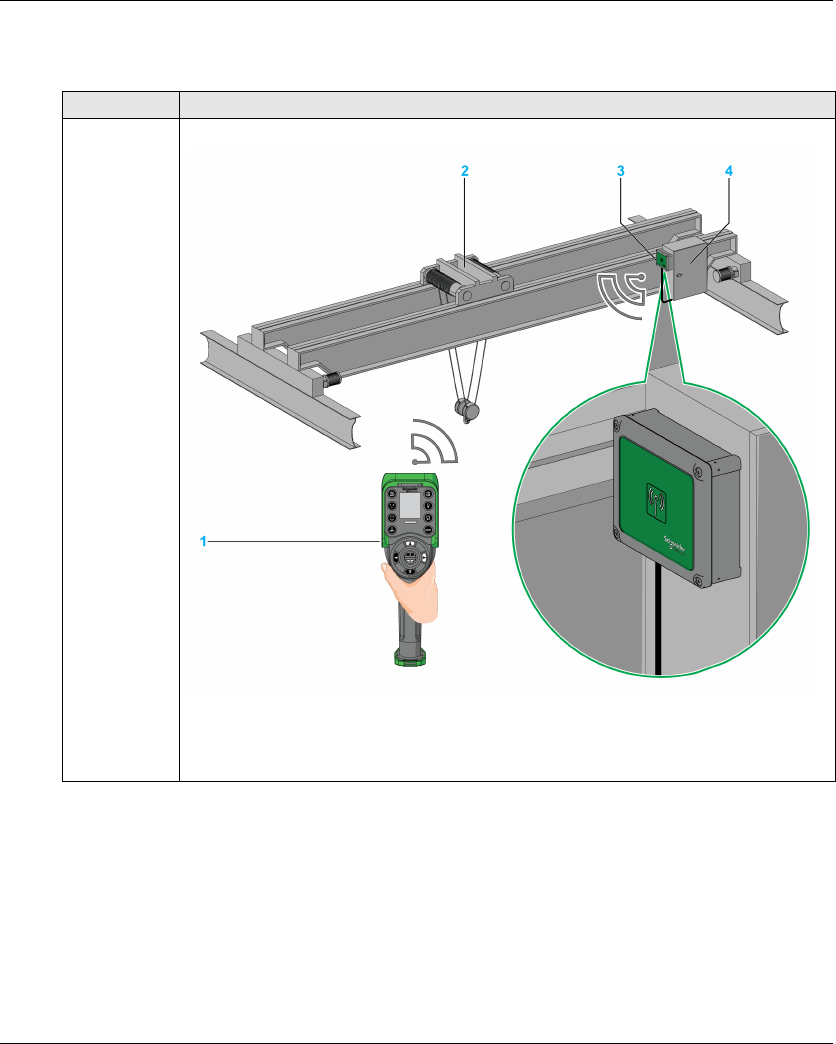
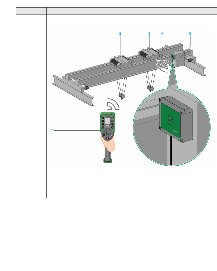
Main Applications
Example of overhead traveling crane:
Type Description
SINGLE
With 1 trolley
The Remote Device controls one trolley.
1 Remote Device
2 Trolley
3 Base Station
4 Electrical cabinet
Wireless Remote Control System
16 EIO0000001505 04/2014
SINGLE
With 2 trolleys
By using the selector button, the Remote Device separately controls the trolley 1, trolley 1+2
or the trolley 2.
1 Remote Device
2 Trolley 1
3 Trolley 2
4 Base Station
5 Electrical cabinet
Type Description
Wireless Remote Control System
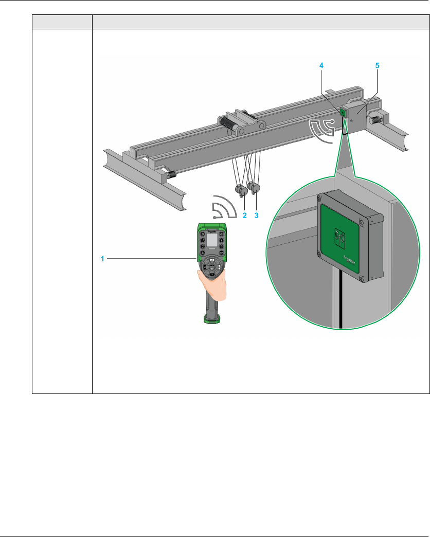
EIO0000001505 04/2014 17
SINGLE
With 2 hooks
By using the selector button, the Remote Device separately controls the hook 1 or the
hook 2.
1 Remote Device
2 Hook 1
3 Hook 2
4 Base Station
5 Electrical cabinet
Type Description
Wireless Remote Control System
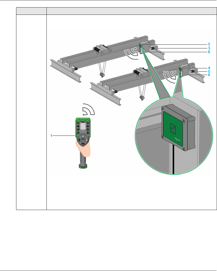
18 EIO0000001505 04/2014
*: TANDEM mode will be available on Q4 2014
TANDEM*By using the selector button, the Remote Device separately controls the bridge 1, bridge 1+2
or the bridge 2.
1 Remote Device
2 Base Station 1
3 Bridge 1
4 Base Station 2
5 Bridge 2
6 Electrical cabinets
Type Description
Wireless Remote Control System
EIO0000001505 04/2014 19
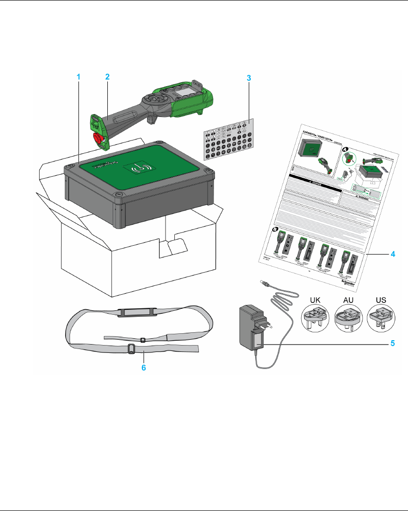
Package Contents
Overview
Applicable items included in the package:
1 Base Station
2 Remote Device
3 Set of labels to customize the Remote Device buttons
4 Instruction Sheet
5 Charger of the Remote Device battery (only in starting kits)
6 Shoulder belt for the Remote Device (only in starting kits)

Wireless Remote Control System
20 EIO0000001505 04/2014
Parts Identification and Main Features
Wireless Remote Control System Overview
The Wireless Remote Control System is a combination of 2 kinds of devices:
Base Station:
Remote Device:
Therefore, 3 levels of complexity for Wireless Remote Control System:
NOTE: Extended and complex systems (XARS•D) can support TANDEM mode (see page 15).
Starting kits:
References ZARB12W ZARB12H ZARB18W ZARB18H
Connectors Cable gland for wires Industrial plug type Cable gland for wires Industrial plug type
No. of inputs 0 18
No. of relays 12 18
Features ZART8L ZART8D ZART12D
Number of configurable buttons 8 8 12
Operator interface LEDs Display Display
Complexity level description Reference
Wireless Remote
Control System
Remote Device Base Station
Basic system:
For simple applications, which include
up to 2 auxiliary buttons
XARS8L12W ZART8L ZARB12W
XARS8L12H ZART8L ZARB12H
Extended system:
For adapted applications which
include up to 2 auxiliary buttons
XARS8D18W ZART8D ZARB18W
XARS8D18H ZART8D ZARB18H
Complex system:
For complex applications which
include up to 6 auxiliary buttons
XARS12D18W ZART12D ZARB18W
XARS12D18H ZART12D ZARB18H
Reference
Starting Kit System Accessories
XARSK8L12W XARS8L12W ZARC01 + ZARC02
XARS8KL12H XARS8L12H ZARC01 + ZARC02
XARS8KD18W XARS8D18W ZARC01 + ZARC02
Wireless Remote Control System
EIO0000001505 04/2014 21
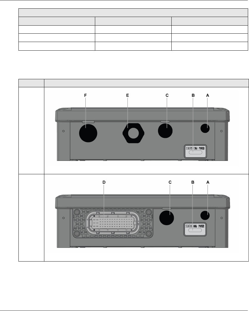
Base Station Parts Identification
XARS8KD18H XARS8D18H ZARC01 + ZARC02
XARSK12D18W XARS12D18W ZARC01 + ZARC02
XARSK12D18H XARS12D18H ZARC01 + ZARC02
Reference
Starting Kit System Accessories
Side Description
Front
ZARB•W
Front
ZARB•H
Wireless Remote Control System
22 EIO0000001505 04/2014
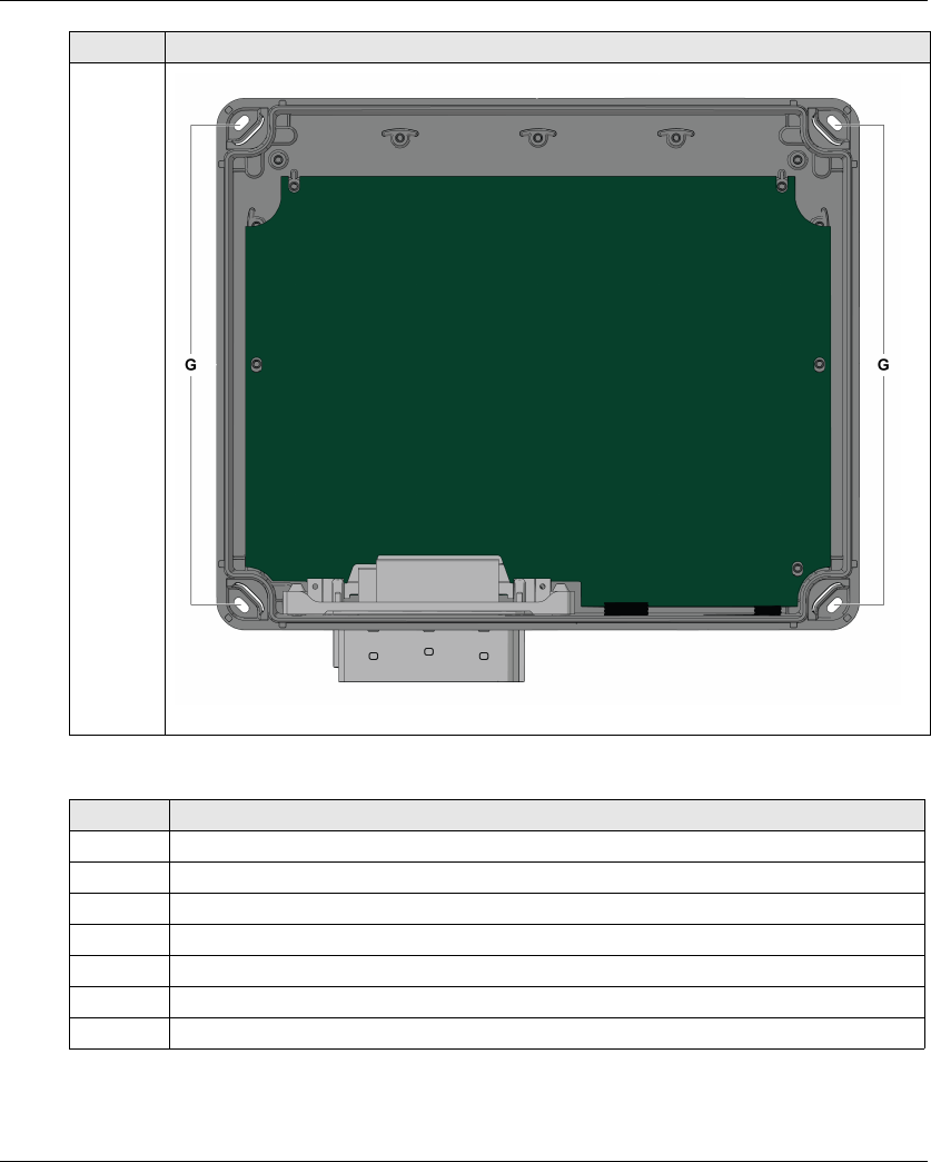
Rear
without
the cover
Part Description
A M12 for external antenna (covered by cap)
B Status LEDs
C M20 for the safeguarding function input wires (covered by cap)
D 62 pins connector (covered by cap)
E M25 for output wires (covered by cable gland)
F M25 for detected applicative alarms input wires (covered by cap)
G 4 holes for standard mounting on support (covered by cap)
Side Description

Wireless Remote Control System
EIO0000001505 04/2014 23
Base Station Main Features
References ZARB12W ZARB12H ZARB18W ZARB18H
Radio communication Yes
External antenna connector Yes
Connectors Cable gland for
wires
Industrial plug
type
Cable gland for
wires
Industrial plug
type
Q0 safety relays outputs 2 (Q0_A, Q0_B)
IN0 / S2_S3 feedback loop
terminals for mirror contacts
from safety actuator
1
Configurable inputs for
detected applicative alarms
0 6 (IN1…IN6)
Inputs dedicated for
safeguarding function
0 12 (IN7…IN18)
Motion & auxiliary standard
relays
12 (Q1…Q12) 18 (Q1…Q18)
Power supply 24…240 V ac/dc 24…48 V ac/dc 24…240 V ac/dc 24…48 V ac/dc
Current consumption AC:
535…250 mA,
50/60 Hz
DC: 328…44 mA
AC:
535…312 mA,
50/60 Hz
DC:
328…155 mA
AC:
535…250 mA,
50/60 Hz
DC: 328…44 mA
AC:
535…312 mA,
50/60 Hz
DC:
328…155 mA
System earthing TN, TT, IT
Q0_A contact voltage 24…240 V ac/dc 24…48 V ac/dc 24…240 V ac/dc 24…48 V ac/dc
Q0_B contact voltage
Motion / auxiliary contact
voltage used by group
Motion / auxiliary contact group Q1…Q3
Q4…Q6
Q7…Q9
Q10…Q12
Q1…Q3
Q4…Q6
Q7…Q9
Q10…Q12
Q13…Q16
Motion / auxiliary relay in
NO+NC type
- Q17, Q18
Wireless Remote Control System
24 EIO0000001505 04/2014
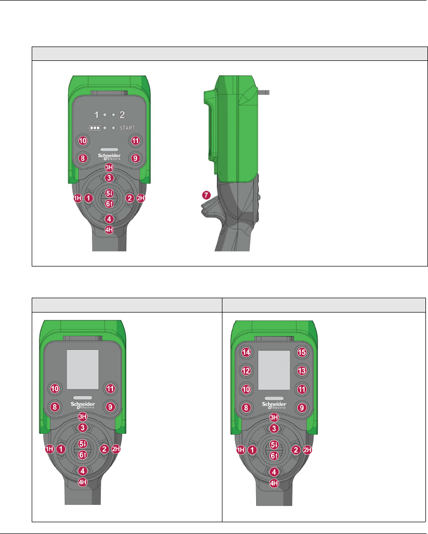
Remote Device Front View Parts Identification
ZART8L
ZART8D ZART12D

Wireless Remote Control System
EIO0000001505 04/2014 25
Remote Device Rear View Parts Identification
1 Cover
2 RJ45 connector
3 Reset button
Part Description
1, 1H, 2, 2H, 3, 3H, 4, 4H, 5, 6 Motion buttons
7 Trigger button
8 OFF/STOP button
9 ON/START/Horn button
10,11,12,13,14,15 Auxiliary buttons
Wireless Remote Control System
26 EIO0000001505 04/2014
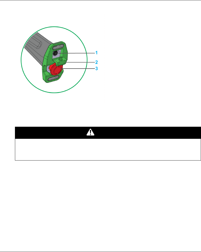
Remote Device Bottom Display Parts Identification
1 Remote Device battery charge connector
2 Protective plug
3 E-STOP button
DANGER
OBSTRUCTED PUSH-BUTTON MOTION
Ensure push-button will fully operate.
Failure to follow these instructions will result in death or serious injury.
Wireless Remote Control System
EIO0000001505 04/2014 27
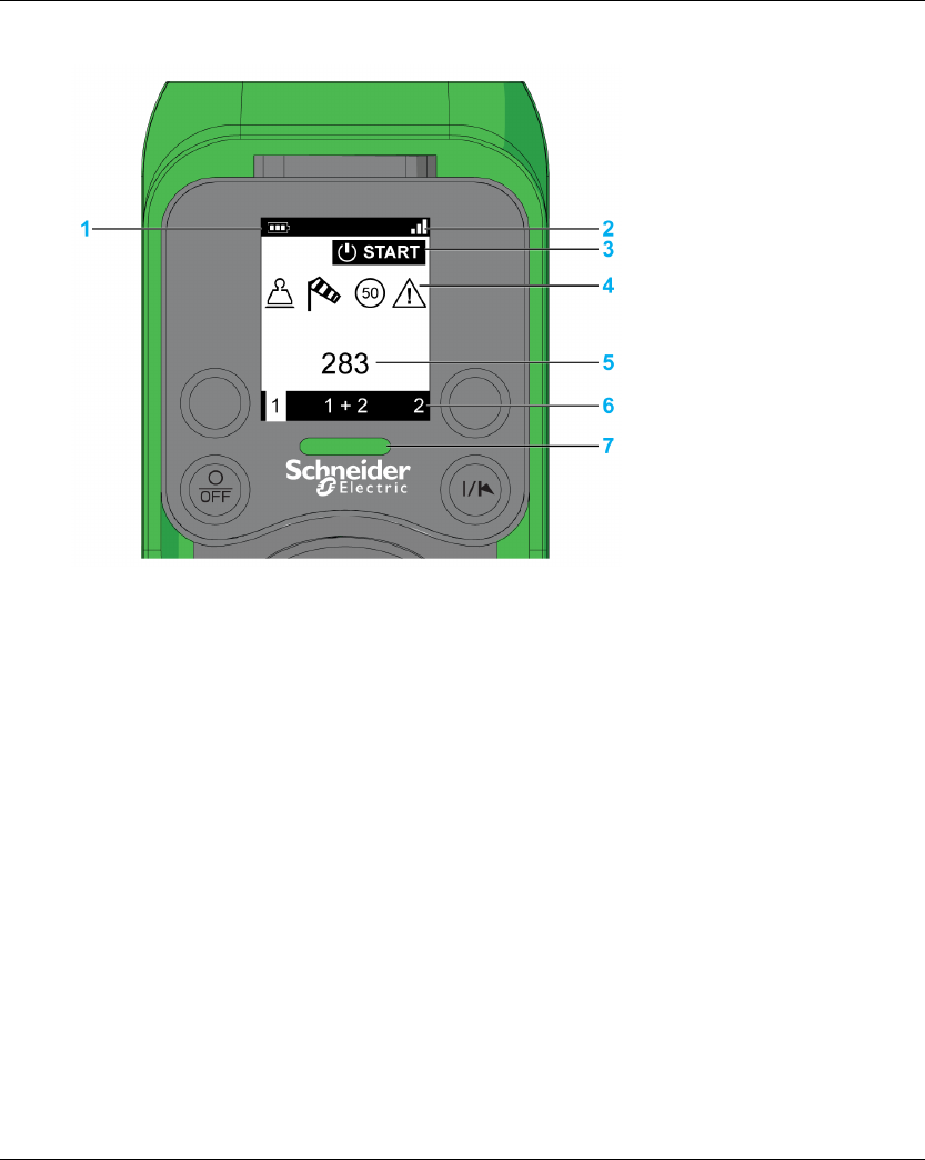
ZART•D Display Parts Identification
1 Battery level
2 Radio communication level
3 Operating status
4 Bridge label
5 Detected applicative alarms
6 Selector status
7 E-STOP LED
Wireless Remote Control System
28 EIO0000001505 04/2014
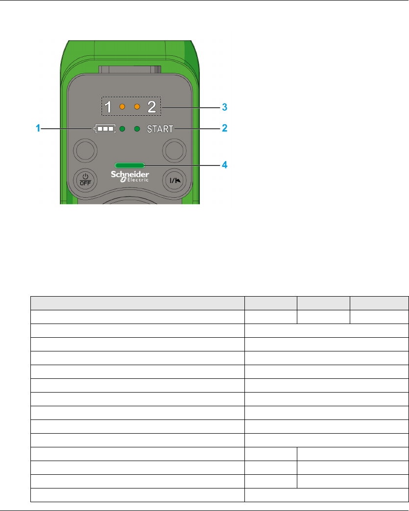
ZART8L Display Parts Identification
1 Battery level LED
2 START LED
3 Selector LEDs
4 E-STOP LED
Remote Device Functionalities
Description ZART8L ZART8D ZART12D
Number of configurable buttons 8 8 12
OFF/STOP button Yes
ON/START/Horn button Yes
Motion & Stop function Yes
Selector 2 or 3 positions (1, 1+2, 2) Yes
E-STOP function Yes
Optional E-STOP reset code sequence Yes
Optional START code sequence Yes
Optional automatic STOP function after a time-out Yes
Optional automatic Power OFF function after a time-out Yes
Information LEDs Yes No
Display function No Yes
Vibrate facility function in case of detected applicative alarms No Yes
Embedded accelerometer Yes

Wireless Remote Control System
EIO0000001505 04/2014 29
Certifications and Standards
Environment
The Wireless Remote Control System devices are compliant with:
WEEE, directive 2002/96/EC
REACH, regulation 1907/2006
RoHS, directive 2011/65/EU
Overall Standards
Local Standards and Certifications
Schneider Electric submitted this product for independent testing and qualification by third party
listing agencies.
Criteria Level
Principles of design for safety EN IEC 60204-1
EN ISO 13849-1
EN ISO 13849-2
EN IEC 62061
EN IEC 61508
EN ISO 13850
Specific standards for hoisting applications EN IEC 60204-32
EN 13557
Low voltage equipment EN IEC 61010-1
EN IEC 60947-5-1
EN IEC 60947-5-4
EN IEC 60947-5-5
Electromagnetic compatibility IEC 61000-6-2
Transmission frame format EN 60870-5-1
Criteria Description
CE marking Machinery directive 2006/42/EC
Low voltage directive 2006/95/EC
EMC directive 2004/108/EC
R&TTE directive 1999/05/EC
Low voltage equipment EN 50178
European specific standards for
hoisting applications
EN 13557
EN 12077-2
EN 15011
European specific standards for
hoisting machines
EN 15011 (overhead traveling cranes)
EN 14439 (tower cranes)
EN 14492 (block hoists and winches)
Wireless Remote Control System
30 EIO0000001505 04/2014
Radio Frequencies Certification
The eXLhoist devices have obtained, or in the process of obtaining, the radio frequency conformity
delivered by the following certification organisms:
Countries certifications (electrical
devices)
CCC
UL508 for base + UL functional safety
CSA C22-2 n°14
Gost
C-tick
KC
US-specific standards for safety UL 1998 (Covered by IEC 61508)
UL 991
Canadian specific standards for
safety
CSA 22.2 N°0.8 (Covered by UL 991)
Standards for radio frequencies ETSI EN 301 489 -1
ETSI EN 301 489 -3
ETSI EN 301 489-17
ETSI EN 300 440-2
ETSI EN 300 328
FCC part 15
RSS GEN issue 3
RSS 210 issue 8
ARIB STD-T81
Criteria Description
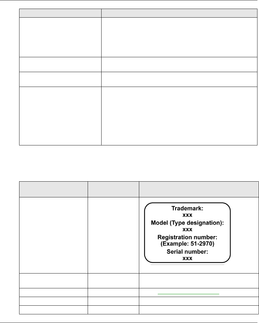
Certification organism Certification
organism country
Certification marks
CNC Argentine
RCM Australia/New-
Zealand
See on the device
ANATEL Brazil See on www.schneider-electric.com.
IC Canada See on the device
SUBTEL Chili See on the device
Wireless Remote Control System
EIO0000001505 04/2014 31
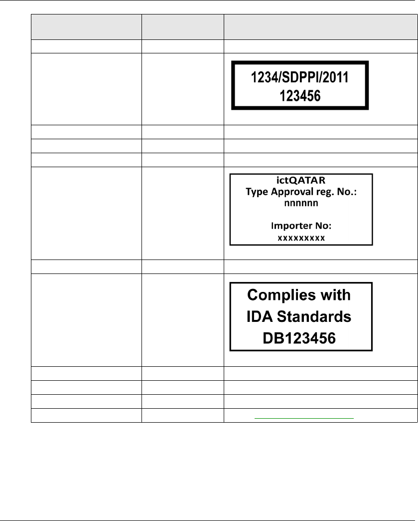
SRRC China SRRC See on the device
SDPPI Indonesia
Technical Conformity Mark Japan See on the device
SIRIM Malaysia See on the device
COFETEL Mexico See on the device
ictQATAR Qatar
EAC Russia See on the device
IDA Singapore
ICASA South Africa See on the device
KCC South Korea See on the device
NCC Taiwan See on the device
NTC SDoC Thailand See on www.schneider-electric.com.
Certification organism Certification
organism country
Certification marks
Wireless Remote Control System
32 EIO0000001505 04/2014
TRA United Arab Emirates
FCC USA See on the device
Certification organism Certification
organism country
Certification marks

Wireless Remote Control System
EIO0000001505 04/2014 33
Accessories
Base Station Accessories
Remote Device Accessories
Reference Description
ZARC03 External antenna for Base Station:
The use of this accessory allows an increase of the radio range in severe environment
conditions.
ZARC05 Connector plug female with cable 1.5 m (4.92 ft) for ZARB•H
ZARC06 Cable gland kit with wire grommets
ZARC09 Kit silent bloc:
Use this accessory in case of applications with severe vibration constraints.
NSYAEFTB Optional mounting:
Use this accessory for external mounting on support (x4).
To be assembled on box before mounting on support.
ZARC12 Connector plug female with cable 3 m (9.84 ft) for ZARB•H
ZARC18 Connector plug female with cable 5 m (16.4 ft) for ZARB•H
Reference Description
ZARC01 Charger
ZARC02 Shoulder belt
ZARC04 Holder
ZARC07 Kit of adhesive labels in B/W for Remote Device
ZARC08 Kit of adhesive labels in color for Remote Device and hoisting system
ZARC20 Kit of pad and trigger
ZARC21 Rubber protection

Wireless Remote Control System
34 EIO0000001505 04/2014


EIO0000001505 04/2014 37
Base Station Specifications
Environment
The Base Station specifications are described in the table:
Specifications Details Value
ZARB•H ZARB•W
Product certifications - CE, UL/CSA, CCC, Gost
Environment - RoHS compliant
Life time - 10 years
Degree of protection - IP65
Degree of pollution - 3
Operating temperature For 24…48 V ac/dc power
supply
-25…70 °C (-13…158 °F)
For 48…130 V ac/dc power
supply
- -25…70 °C
(-13…158 °F)
For 130…240 V ac/dc power
supply
- -25…50 °C
(-13…122 °F)
Storage temperature (for 1 year) - -40…70 °C (-40…158 °F)
Corrosive atmosphere
withstands
IEC-60721-3-3 Level 3C2 on H2S / SO2 / NO2 / Cl2
Fire withstands Power on parts 960 °C 30s / 30s according to
IEC 60695-2-10 and IEC-60695-2-11
Other parts 650 °C 30s / 30s according to
IEC 60695-2-10 and IEC-60695-2-11
Salt mist IEC 60068.2.52 Severity 2
Operating humidity range - 0...97%
Storage humidity range - 0...97%
Altitude Operation
Storage
0...2000 m (0...6561.7 ft)
0...3000 m (0...9842.5 ft)
Vibration resistance IEC-60068-2-6
Use NSYAEFTB silent bloc in
case of applications with
severe vibration constraints
10…55 Hz, amplitude 0.75 mm,
Acceleration 9.8 m/s² (1 gn)
Shock resistance According to IEC 60068-2-27 147 m/s² (15 gn), for 11 ms
Power supply
Over voltage category
-OVC2
Voltage dips IEC-61000-4-11 10 ms
Resistance to electrostatic
discharges
IEC 61000-4-2 4 kV on contact
8kV in air

38 EIO0000001505 04/2014
Safety Specifications
The main safety specifications are described in the table:
Resistance to radiated fields IEC 61000-4-3 10 V/m
Immunity to fast transient IEC 61000-4-4 Power line: 4 kV (direct)
Outputs: 4 kV (direct)
Inputs: 2 kV (coupling)
Surge immunity IEC 61000-4-5 between the
ground and power supply wires
(Common mode)
2kV
IEC 61000-4-5 between the
power supply wires
(Differential mode)
1kV
Immunity to conducted magnetic
fields
Conforming to IEC-61000-4-6 10 V from 150 kHz to 80 MHz
Emission disturbances Conducted & radiated
disturbances
Class B
Specifications Details Value
ZARB•H ZARB•W
Specifications Details Value
Safety relays function
Safety specifications
According to IEC 61508 Ed2 Up to SIL3 capability
According to IEC 62061 Ed1 Up to SIL3 CL capability
EN ISO 13849-1 Up to performance level “e”
Up to category 4
Stop category according to
IEC 60204-32
Category 0
Motion relays function
Safety specifications
According to IEC 61508 Ed2 SIL1 capability
According to IEC 62061 Ed 1 SIL1 CL capability
EN ISO 13849-1 Performance level “c”
Category 1
Stop category according to
IEC 60204-32
Category 0 or 1
IN7...IN18 safeguarding inputs According to IEC 61508 Ed2 SIL1 capability
According to IEC 62061 Ed 1 SIL1 CL capability
EN ISO 13849-1 Performance level “c”
Category 1
Stop category according to
IEC 60204-32
Category 0 or 1

EIO0000001505 04/2014 39
Safety Relays
The safety relays specifications are described in the table:
Specifications Details Value
ZARB•H ZARB•W
Number of contacts The Base Station internally
implements 2 safety relays in
serial. Each safety relay has 2
contacts.
2
Logical type - NO
Insulation between Q0A and
Q0B
- SELV insulation between (Q0A1, Q0A2)
and (Q0B1, Q0B2) for voltage up to
240 Vac
Q0A voltages - Up to 48 Vac 24...240 Vac
Q0B voltages -
Q0A, Q0B
Maximum Ie current
24...240 Vac
-4A6A
Relay type according to
EN/IEC 60947-5-1
AC15 C300 B300
DC13 - R300
Maximum making and
breaking capacities
(100.000 cycles)
AC15 / AC current according to
EN/IEC 60947-5-1
24 Vac 0.75 A
48 Vac 0.38 A
120 Vac - 0.15 A
240 Vac - 0.08 A
Inrush 450 VA
Maintained 45 VA
Maximum making and
breaking capacities
(100.000 cycles)
DC13 / DC current according to
EN/IEC 60947-5-1
24 Vdc 0.6 A
48 Vdc 0.3 A
120 Vdc - 0.12 A
240 Vdc - 0.06 A
Make 14.4 VA
Break
Minimum output current The minimum current is
compatible with the STO
Schneider Electric drive input
impedance of 1.5 kΩ which
means a current of
24 V/1.5 kΩ= 16 mA.
10 mA / 24 Vdc
40 EIO0000001505 04/2014
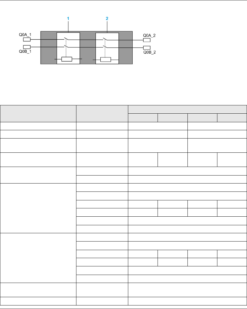
Safety relays internal wiring:
1 Safety relay 1
2 Safety relay 2
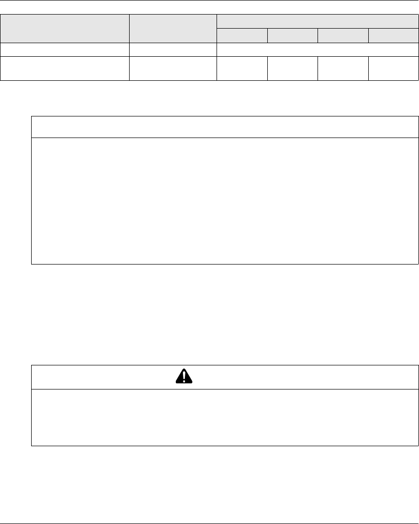
Motion/Auxiliary Relays
The motion/auxiliary relay specifications are described in the table:
Specifications Details Value
ZARB12H ZARB12W ZARB18H ZARB18W
Number of motion/auxiliary relays - 12 18
Normally open (N0) relays - 12 (Q1…Q12) 16 (Q1…Q16)
Normally open + normally closed
(N0+NC) relays
- 0 2 (Q17, Q18)
Nominal output voltage - 24…48 V
ac/dc ±20%
24…240 V
ac/dc ±20%
24…48 V
ac/dc ±20%
24…240 V
ac/dc ±20%
Relay type according to EN/IEC
60947-5-1
AC15 B300
DC13 R300
Maximum making and breaking
capacities
1 000 000 cycles for NO contacts
500 000 cycles for NC contacts
AC15 / AC current according to
EN/IEC 60947-5-1
24 Vac 1.08 A
48 Vac 0.54 A
120 Vac - 0.22 A - 0.22 A
240 Vac - 0.11 A - 0.11 A
Inrush 260 VA
Maintained 26 VA
Maximum making and breaking
capacities
1 000 000 cycles for NO contacts
500 000 cycles for NC contacts
DC13 / DC current according to
EN/IEC 60947-5-1
24 Vdc 0.1 A
48 Vdc 0.05 A
120 Vdc - 0.02 A - 0.02 A
240 Vdc - 0.01 A - 0.01 A
Make 5 VA
Break 5 VA
Minimum output current 6.8 mA with 24 Vdc
voltage
6.8 mA
Maximum operating rate - 2 Hz
EIO0000001505 04/2014 41
Power Supply
Protective Earth Ground
The PE must be connected to the machine to protect against maloperation due to earth faults (IEC
60204-1, Protection against maloperation due to earth faults).
The PE must be connected to the machine ground (IEC 60204-1, protection against electric
shock). If not then the Base Station inputs voltage (IN_COM, S2_S3, IN0…IN18) could increase
to a dangerous voltage because of the possible static electricity induced by the machine motions.
Maximum operating rate - 2 Hz
Weight - 1340 kg
(2954 lb.)
1360 kg
(3644 lb.)
1430 kg
(3831 lb.)
1450 kg
(3885 lb.)
Specifications Details Value
ZARB12H ZARB12W ZARB18H ZARB18W
NOTICE
INOPERABLE EQUIPMENT
The ZARB•H Base Station must be powered with a voltage:
From 24 Vac -15% to 48 Vac +10% with frequency of 50 Hz -6%/+4% and frequency of 60 Hz
-6%/+4%.
From 24 Vdc -15% to 48 Vdc +20%.
The ZARB•W Base Station must be powered with a voltage:
From 24 Vac -15% to 240 Vac +10% with frequency of 50 Hz -6%/+4% and frequency of
60 Hz -6%/+4%.
From 24 Vdc -15% to 240 Vdc +20%.
Failure to follow these instructions can result in equipment damage.
WARNING
UNINTENDED EQUIPMENT OPERATION
Connect the Base Station protective earth ground connection to the machine ground.
Failure to follow these instructions can result in death, serious injury, or equipment
damage.

42 EIO0000001505 04/2014
IN0
The IN0 input specifications are:
Static input type
Current source logic
Compatible only with 2 wiring:
Connection of IN0 to one side to the auxiliary contact of the main contactor and connection
of S2_S3 output port to the other side of the auxiliary contact of the main contactor.
Direct connection to the S2_S3 output.
20 mA typical pulsed input current
IN1…IN18
The IN1 to IN18 input specifications are:
Static input type
Current source logic
Compatible only with 2 wiring:
Connection of INi (i=1…18) in one side of a dry contact and connection of IN_COM output to
the other side of the dry contact.
No INi (i=1…18) connection.
20 mA typical pulsed input current
Response Time
You shall choose the contactors/drives in such way that the process safety time shall be less than
550 ms maximum to be in accordance with the IEC 60204-32.
Input/Output Maximum response time (ms)
E-STOP 300
STOP 300
Motion/Auxiliary 300
Selector 300
Input 300

EIO0000001505 04/2014 43
RADIO Specification
RADIO Specification
FCC USA and IC Canada Compliance Statement
This device complies with part 15 of the FCC Rules and Industry Canada licence-exempt RSS
standard(s). Operation is subject to the following two conditions:
1) This device may not cause harmful interference, and
2) this device must accept any interference received, including interference that may cause
undesired operation.
Le présent appareil est conforme aux CNR d’Industrie Canada applicables aux appareils radio
exempts de licence. L’exploitation est autorisée aux deux conditions suivantes :
1) l’appareil ne doit pas produire de brouillage, et
2) l’utilisateur de l’appareil doit accepter tout brouillage radioélectrique subi, même si le brouillage
est susceptible d’en compromettre le fonctionnement.
Specification Details Value
Frequency of radio
communication
International frequency range 2.4 GHz
Number of working
systems in the same
area
- Up to 50 systems in a 100 x 100 meter
area
Radio range In free field Up to 100 m (328 ft)
In industrial environment Up to 50 m (164 ft) typical
Antenna (Possible ZARC03 external antenna use) Internal
Working channel
selection
No impact for the customer (during
installation, use and maintenance)
Up to 40 channels
ID - MAC address reserved by Schneider
Electric

44 EIO0000001505 04/2014
Changes or modifications not expressly approved by the party responsible for compliance could
void the user’s authority to operate the equipment. This equipment has been tested and found to
comply with the limits for a Class B digital device, pursuant to part 15 of the FCC Rules. These
limits are designed to provide reasonable protection against harmful interference in a residential
installation. This equipment generates, uses and can radiate radio frequency energy and, if not
installed and used in accordance with the instructions, may cause harmful interference to radio
communications. However, there is no guarantee that interference will not occur in a particular
installation. If this equipment does cause harmful interference to radio or television reception,
which can be determined by turning the equipment off and on, the user is encouraged to try to
correct the interference by one or more of the following measures:
Reorient or relocate the receiving antenna.
Increase the separation between the equipment and receiver.
Connect the equipment into an outlet on a circuit different from that to which the receiver is
connected.
Consult the dealer or an experienced radio/TV technician for help.
The base complies with FCC’s radiation exposure limits set forth for an uncontrolled environment
under the following conditions:
1) This equipment should be installed and operated such that a minimum separation distance of
20 cm is maintained between the radiator (antenna) and user’s/nearby person’s body at all
times.
2) This transmitter must not be co-located or operating in conjunction with any other antenna or
transmitter.
The remote device with it’s antenna complies with FCC’s radiation exposure limits set forth for an
uncontrolled environment. To maintain compliance, follow the instructions below:
1) This transmitter must not be co-located or operating in conjunction with any other antenna or
transmitter.
2) Avoid direct contact to the antenna, or keep contact to a minimum while using this equipment.
Under Industry Canada regulations, these radio transmitters may only operate using an antenna
of a type and maximum (or lesser) gain approved for the transmitter by Industry Canada. To reduce
potential radio interference to other users, the antenna type and its gain should be so chosen that
the equivalent isotropically radiated power (e.i.r.p.) is not more than that necessary for successful
communication. These radio transmitters (IC:7002CZARB and IC:7002CZART) have been
approved by Industry Canada to operate with the antenna type ZARC03 with the maximum
permissible gain and required antenna impedance. Any other antenna types having a gain greater
than the maximum gain indicated for that type, are strictly prohibited for use with this device.

EIO0000001505 04/2014 45
Conformément à la réglementation d’Industrie Canada, les présents émetteurs radio peuvent
fonctionner avec une antenne d’un type et d’un gain maximal (ou inférieur) approuvé pour
l’émetteur par Industrie Canada. Dans le but de réduire les risques de brouillage radioélectrique à
l’intention des autres utilisateurs, il faut choisir le type d’antenne et son gain de sorte que la
puissance isotrope rayonnée équivalente (p.i.r.e.) ne dépasse pas l’intensité nécessaire à
l’établissement d’une communication satisfaisante. Les présents émetteurs radio (identifier
IC:7002CZARBo and IC:7002CZARTo) ont été approuvé par Industrie Canada pour fonctionner
avec le type d’antenne ZARC03 ayant un gain admissible maximal et l’impédance requise.
D’autres types d’antenne non dont le gain est supérieur au gain maximal indiqué, sont strictement
interdits pour l’exploitation de l’émetteur.
Any changes or modifications not expressly approved by Schneider Electric could void the user’s
authority to operate the equipment.
Product
reference
Maximum gain of internal
antenna (dB)
Maximum gain of external
antenna (dB)
(including cable)
Allowed impedance (Ω)
ZART8L 4.5 – 50
ZATL8D 5.5
ZART12D
ZARB12H 4.5 1
ZARB12W
ZARB18H
ZARB18W


EIO0000001505 04/2014 47
Remote Device Specifications
Environment
Specification Details Value
Product certifications - CE, UL/CSA, CCC, Gost
Safety certification - TÜV, UL safety
Battery life time Conforming to IEC-62133 > 2 years
Battery type - LiFePO4 3.3 V / 1 Ah
Mechanical life Motion buttons 5 000 000 cycles
Mechanical life Auxiliary buttons 5 000 000 cycles
Temperature Storage (for 1 year) -20…45 °C (-4…113 °F)
Operating -20…60 °C (-4…140 °F)
Relative humidity Operating/Storage -25…60 °C (-13…140 °F), 0%...95%,
without condensation
Corrosive atmospheres
resistance
IEC 60721-3-3 Level of 3C2 on H2S / SO2 / NO2 / Cl2
Degree of protection - IP65 and NEMA type 4
Altitude Operation
Storage
0...2000 m (0...6561.7 ft)
0...3000 m (0...9842.5 ft)
Vibration resistance Conforming to IEC 60068-2-6 10…55 Hz, amplitude 0.75 mm,
acceleration 15 gn
Shock resistance Conforming to IEC 60068-2-27 100 gn
Mechanical protection - Bumper
Resistance to electrostatic
discharges
Conforming to IEC 61000-4-2 4 kV on contact
8kV in air
Resistance to radiated fields Conforming to IEC 61000-4-3 10 V/m
Immunity to fast transient Conforming to IEC 61000-4-4 1 kV, on power supply
Immunity to power
frequency magnetic field
- 30 A/m minimum
Mechanical materials - Bumper in onflex material
Housing visibility - Green color
Weight - 594 g (21 oz)

48 EIO0000001505 04/2014
Remote Device Charger Specification
Environment
Specification Value
Location to be used Residential, commercial, and light-industrial
environment (IEC 61000-6-3)
Product certifications CE, UL/CSA, CCC, Gost
Degree of protection IP2x
Degree of pollution 2
Operating temperature 10…40 °C (50…104 °F)
Storage temperature (for 1 year) -20…60 °C (-4…140 °F)
Primary supply voltage 240 Vac +/-20%
110 Vac +/-20%
Secondary output voltage 12 V, SELV voltage
Secondary output power 30 W minimum

50 EIO0000001505 04/2014
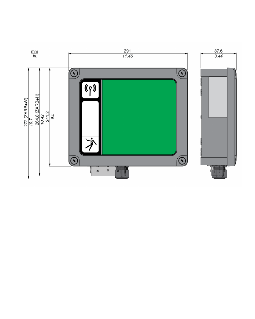
Base Station Dimensions
Dimensions
The following figure shows the Base Station dimensions:
EIO0000001505 04/2014 51
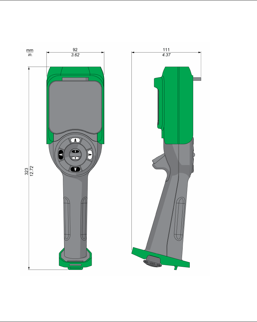
Remote Device Dimensions
Dimensions
The following figure shows the Remote Device dimensions:

52 EIO0000001505 04/2014

EIO0000001505 04/2014 53
Harmony eXLhoist
Safety
EIO0000001505 04/2014
Safety
Chapter 3
Safety
What Is in This Chapter?
This chapter contains the following sections:
Section Topic Page
3.1 Generalities 54
3.2 Description and Safety Function Capability 61
3.3 Functional Safety Function Commissioning 73
3.4 Functional Safety Requirements for Maintenance 77


Safety
EIO0000001505 04/2014 55
Introduction
Overview
The safety functions incorporated in eXLhoist allow you to develop applications oriented towards
protection of people and machinery.
Some safety functions are configured with eXLhoist Configuration Software.
Integrated safety functions provide the following benefits:
Additional standards-compliant safety functions
No need for external safety devices
Reduced wiring effort and space requirements
Reduced costs
The eXLhoist is compliant with the requirements of the standards in terms of implementation of
safety functions.

Safety
56 EIO0000001505 04/2014
Standards and Terminology
Overview
The technical terms, terminology, and the corresponding descriptions in this manual normally use
the terms or definitions in the relevant standards.
In the field of Wireless Remote Control System, this includes, but is not limited to, terms such as
safety function, safe state, fault, fault reset, failure, error, error message, warning, warning
message, and so on.
These standards include:
IEC 61508 Ed.2 series: Functional safety of electrical/electronic/programmable electronic
safety-related systems
IEC 62061 Ed.1.0: Safety of machinery - Functional safety of safety-related electrical,
electronic, and programmable electronic control systems
EN ISO 13849-1 & 2 Safety of machinery - Safety related parts of control systems
EC Declaration of Conformity
The EC declaration of conformity for the machine directive 2006/42/EC can be obtained on
www.schneider-electric.com.
Functional Safety Certification
The integrated safety functions are compatible with:
EN 15011: 2011
EN 14492-2: 2009
EN 14439: 2009
EN 13557: 2008
IEC 60204-1: 2009
IEC 60204-32: 2008
The listed standards set out safety-related considerations of Wireless Remote Control System
safety related in terms of the framework of the ISO13849-1 and ISO13849-2 standards.
The defined safety functions are:
SIL1, SIL2, and SIL3 capability in compliance with the IEC 61508 Ed.2 series.
Performance Level c, d, and e in compliance with ISO 13849-1.
Compliant with category 2, 3, and 4 of European standard ISO 13849-1.
Also refer to Safety Function Capability (seepage61).
The safety demand operating mode is considered to be high demand or continuous mode of
operation according to the IEC 61508-1 standard.
The functional safety certificate is accessible on www.schneider-electric.com.

Safety
EIO0000001505 04/2014 57
Basics
Functional Safety
Automation and safety engineering are 2 areas that were separate in the past but have recently
become more and more integrated.
The engineering and installation of complex automation solutions are greatly simplified by
integrated safety functions.
Usually, the safety engineering requirements depend on the application.
The level of requirement results from the risk and the hazard potential arising from the specific
application.
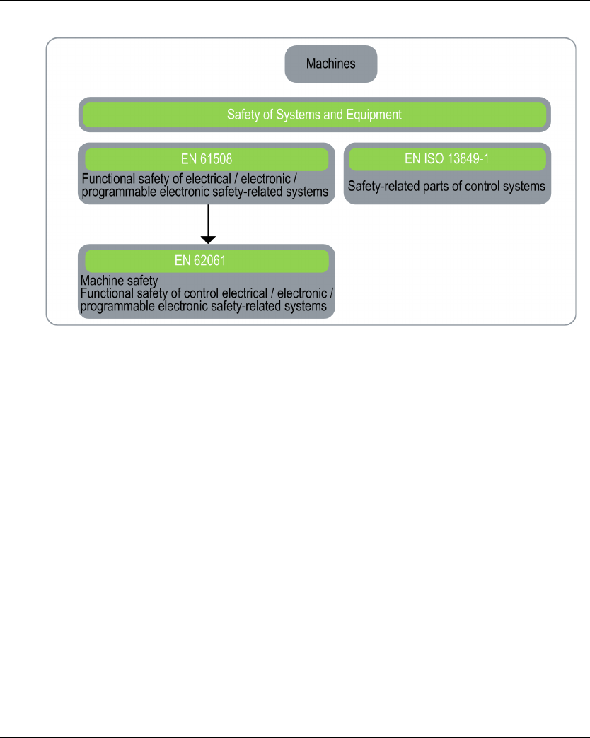
IEC 61508 Standard
The standard IEC 61508 functional safety of electrical/electronic/programmable electronic safety-
related systems covers the safety-related function.
Instead of a single component, an entire function chain (for example, from a sensor through the
logical processing units to the actuator) is considered as a unit.
This function chain must meet the requirements of the specific safety integrity level as a whole.
Systems and components that can be used in various applications for safety tasks with comparable
risk levels can be developed on this basis.
ISO13849 Standard or IEC62061 Standard
Designers can follow either EN ISO 13849-1 or EN 62061 to demonstrate conformity with the
Directive 2006/42/EC on machinery. These 2 new standards consider not only whether a fault will
occur, but also how likely it is to occur.
This means that there is a quantifiable, probabilistic element in compliance: machine builders must
be able to determine whether their safety circuit meets the required Safety Integrity Level (SIL) or
Performance Level (PL). Panel builders and designers should be aware that manufacturers of the
components used in safety circuits (such as safety detection components, safety logic solvers, and
output devices like contactors) must provide detailed data on their products.
Safety
58 EIO0000001505 04/2014
Safety standards:
SIL - Safety Integrity Level
The standard IEC 61508 defines 4 Safety Integrity Levels (SIL) for safety functions.
SIL1 is the lowest level and SIL4 is the highest level.
A hazard and risk analysis serves as a basis for determining the required SIL.
This is used to decide whether the relevant function chain is to be considered as a safety function
and which hazard potential it must cover.
PF - Probability of Failure
The standard IEC 61508 defines SIL using requirements grouped into 2 broad categories:
hardware safety integrity and systematic safety integrity. A device or system must meet the
requirements for both categories to achieve a given SIL.
The SIL requirements for hardware safety integrity are based on a probabilistic analysis of the
device. To achieve a given SIL, the device must meet targets for the maximum probability of
dangerous failure and a minimum Safe Failure Fraction. The concept of “dangerous failure” must
be rigorously defined for the system in question, normally in the form of requirement constraints
whose integrity is verified throughout system development. The actual targets required vary
depending on the likelihood of a demand, the complexity of the devices, and types of redundancy
used.

Safety
EIO0000001505 04/2014 59
The Probability of Failure on Demand (PFD) of low demand operation for different SILs are defined
in IEC 61508 are as follows:
In continuous operation, these changes to the following:
A function is considered as "on demand" if the demand rate is lower than one activation per year.
Otherwise, the function is considered as "High demand or continuous operation".
The hazards of a control system must be identified then analyzed in a risk analysis. These risks
are gradually mitigated until their overall contribution to the hazard is deemed to be acceptable.
The tolerable level of these risks is specified as a safety requirement in the form of a target
probability of a dangerous failure over a given period, stated as a discrete SIL level.
PL - Performance Level
The standard IEC 13849-1 defines 5 Performance Levels (PL) for safety functions.
"a" is the lowest level and "e" is the highest level.
5 levels (a, b, c, d, and e) correspond to different values of average probability of dangerous failure
per hour.
SIL Average Probability of a Dangerous Failure on Demand of the safety function
PFD
SIL4 < 10-4
SIL3 ≥ 10-4 to < 10-3
SIL2 ≥ 10-3 to < 10-2
SIL1 ≥ 10-2 to < 10-1
SIL Average Frequency of a Dangerous Failure on Demand of the safety function (h-1)
PFH
SIL4 ≥ 10-9 to < 10-8
SIL3 ≥ 10-8 to < 10-7
SIL2 ≥ 10-7 to < 10-6
SIL1 ≥ 10-6 to < 10-5
PL Probability of a Dangerous Hardware Failure Per Hour
e≥ 10-8 to < 10-7
d≥ 10-7 to < 10-6
c≥ 10-6 to < 3*10-6
Safety
60 EIO0000001505 04/2014
HFT - Hardware Fault Tolerance and SFF - Safe Failure Fraction
Depending on the SIL for the safety system, the IEC 61508 standard requires a specific HFT in
connection with a specific proportion of safe failures SFF.
The HFT is the ability of a system to execute the required safety function in spite of the presence
of one or more hardware faults.
The SFF of a system is defined as the ratio of the rate of safe failures to the total failure rate of the
system.
According to IEC 61508, the maximum achievable SIL of a system is partly determined by the HFT
and the SFF of the system.
IEC 61508 distinguishes 2 types of subsystem (type A subsystem, type B subsystem).
These types are specified on the basis of criteria which the standard defines for the safety-relevant
components.
Systematic Safety Integrity & Detect Fault Avoidance Measures
Systematic errors in the specifications, in the hardware and the software, usage faults and
maintenance faults in the safety system must be avoided to the maximum degree possible. To
reach these requirements, IEC 61508 specifies a number of measures for fault avoidance that
must be implemented depending on the required SIL. These measures for fault avoidance must
cover the entire life cycle of the safety system, that is, from design to decommissioning of the
system.
b≥ 3*10-6 to < 10-5
a≥ 10-5 to < 10-4
PL Probability of a Dangerous Hardware Failure Per Hour
SFF HTF
Type A subsystem Type B subsystem
012012
< 60% SIL1 SIL2 SIL3 ---- SIL1 SIL2
60% ... < 90% SIL2 SIL3 SIL4 SIL1 SIL2 SIL3
90% ... < 99% SIL3 SIL4 SIL4 SIL2 SIL3 SIL4
≥ 99% SIL3 SIL4 SIL4 SIL3 SIL4 SIL4

Safety
EIO0000001505 04/2014 61
Description and Safety Function Capability
Section 3.2
Description and Safety Function Capability
What Is in This Section?
This section contains the following topics:
Topic Page
Wireless Remote Control System Safety Functions Are Part of an Overall System 62
Getting and Operating the Safety Function 63
E-STOP 64
STOP Function 65
Standard Motion & Auxiliary Functions 66
Safeguarding 67
Priority of Safety Functions 68
Safe State of the Wireless Remote Control System 69
Response Time and Process Safety Time (PST) 70
Legal RFU (Recommendation for Use) 71
Summary of the Reliability Study 72

Safety
62 EIO0000001505 04/2014
Wireless Remote Control System Safety Functions Are Part of an Overall System
Overview
The qualitative and quantitative safety objectives determined by the final application require some
adjustments to ensure safe use of the safety functions. The integrator of the Wireless Remote
Control System is responsible for these additional changes (for example, managing the
mechanical brake on the motor).

Safety
EIO0000001505 04/2014 63
Getting and Operating the Safety Function
Overview
The SISTEMA software allows machine developers and testers of safety-related machine controls
to evaluate the safety standard or level of their machine in the context of ISO 13849-1. The tool
allows you to model the structure of safety-related control components based on the designated
architectures, allowing automated calculation of the reliability standards with various levels of
detail, including that of the Performance Level (PL).
The eXLhoist libraries are available from www.schneider-electric.com.

Safety
64 EIO0000001505 04/2014
E-STOP
Overview
For general descriptions, refer to E-STOP function (see page 121).
The E-STOP is not configurable.
The undesired event of the E-STOP function is masking of E-STOP activation.
The safe state of the E-STOP function is to open safety relays.
For a SIL3 PLe E-STOP, auxiliary contact of contactors must be mechanically linked. Contactors
shall be compliant with:
EN 60947-4-1:2010 Annex F (preferred) - Requirements for auxiliary contact linked to power
contact (mirror contact), or
EN 60947-5-1:2004 Annex L - Special prescription for elements with contact mechanically
linked.
In order to be compliant with the Common Cause of Failure (CCF), wiring of redundant contactors
or drives must be by different path.
The standard E-STOP function of eXLhoist is limited to a stop category 0 according to IEC 60204-
32. If some applications require an E-STOP function with a stop category 1, then a safety relay type
Preventa XPS ATE or XPS AV or similar must be used.
In order to justify of the safety category 4 according to ISO13849-1, an automatic diagnostic is
realized on IN0 terminal thanks to the S2_S3 terminal (Pulsed 12 V). An external supply of IN0
input cannot be used.
E-STOP function is a passive stop (function activated when an invalid frame is detected).
Function Installation IEC 60204-32 IEC 61508 IEC 62061 ISO 13849
STOP
category
SIL SIL CL Safety
category
PL
E-STOP With auxiliary
contact loop
between S2_S3
and IN0
Category SIL3 SIL3 CL Safety
category
PL e
Without auxiliary
contact loop
between S2_S3
and IN0
SIL2 SIL2 CL Safety
category
PL d

Safety
EIO0000001505 04/2014 65
STOP Function
Overview
For general descriptions, refer to STOP function (seepage123).
The undesired event of the STOP function is masking of STOP activation.
The safe state of the STOP function is to open safety relays.
STOP function is a passive stop (function activated when an invalid frame is detected).
Function Installation IEC 60204-32 IEC 61508 IEC 62061 ISO 13849
STOP
category
SIL SIL CL Safety
category
PL
STOP No UOC Category 0 SIL2 SIL2 CL Safety
category 3
PL d
With UOC Category 1

Safety
66 EIO0000001505 04/2014
Standard Motion & Auxiliary Functions
Overview
For general descriptions, refer to Standard Motion (seepage131) and Auxiliary functions
(seepage133).
A relay assignment can be done for the Remote Device motion buttons with the eXLhoist
Configuration Software. An UOC relay (see page 105) can be associated to a motion axis (and its
motion relays) thanks to the eXLhoist Configuration Software.
Auxiliary functions can be assigned to auxiliary buttons and relays thanks to the eXLhoist
Configuration Software.
The undesired event of standard motion & auxiliary functions is the unintended standard motion or
auxiliary function activation.
The safe state of the standard motion & auxiliary function is to open safety relays.
In order to justify of the safety category 2, an automatic diagnostic is realized on buttons of the
Remote Device when the Remote Device is switched ON and during a START of the machine. So
during these 2 phases, the operator must not push any motion or auxiliary buttons.
Standard motion & auxiliary functions are passive stop functions (functions activated when an input
signal is detected).
Function Installation IEC 60204-32 IEC 61508 IEC 62061 ISO 13849
STOP
category
SIL SIL CL Safety category PL
Standard
motion &
auxiliary
functions
No UOC Category 1 SIL1 SIL1 CL Category 2 for
electronic parts
Category 1 for
electromechanical
parts
PL c
With UOC
Safety
EIO0000001505 04/2014 67
Safeguarding
Overview
For general description, refer to Safeguarding function (see page 107).
Safeguarding can be assigned to a motion direction thanks to the eXLhoist Configuration Software.
The undesired event of Safeguarding function is the no disabling of motion buttons.
Safeguarding limit switches contacts must be NC contacts.
The safe state of the Safeguarding function is to open safety relays.
Safeguarding input signal:
In order to justify of the safety category 2, an automatic diagnostic is realized on the Safeguarding
inputs thanks to the IN_COM output port. An external power supply of Safeguarding inputs cannot
be used.
Safeguarding is a passive stop function (function activated when an input signal is detected).
Function Installation IEC 60204-32 IEC 61508 IEC 62061 ISO 13849
STOP
category
SIL SIL CL Safety category PL
Safeguarding NC Category 2 on
the motion
direction
SIL1 SIL1 CL Category 2 for
electronic parts
Category 1 for
electromechanic
al parts
PL c
Input signals limit switch Units Value
Logic 0 (Ulow) V < 1
Logic 1 (Uhigh) V > 2
Impedance kΩ1.5
Debounce time ms 1
Response time of safety function ms < 300

Safety
68 EIO0000001505 04/2014
Priority of Safety Functions
Overview
Priority of safety functions Safety functions
1E-STOP
2STOP
3 Safeguarding
4 Standard motion & auxiliary functions

Safety
EIO0000001505 04/2014 69
Safe State of the Wireless Remote Control System
Overview
Safe states of the Base Station are:
SAFE-STOP failure: if a failure is detected by the Base Station, the Base Station opens safety
relays with a stop category 0 and stops the radio communication with the Remote Device.
SAFE-STOP radio: if the Base Station looses the communication with the Remote Device, the
Base Station opens the safety relays in stop category 0 or stop category 1 according to the
commissioning.
The Safe state position of the Remote Device is no communication with the base station: if a failure
is detected in the Remote Device, the Remote Device stops the radio communication. So the Base
Station goes to SAFE-STOP radio mode and opens the safety relays in stop category 0 or stop
category 1 according to the commissioning.
Safety
70 EIO0000001505 04/2014
Response Time and Process Safety Time (PST)
Overview
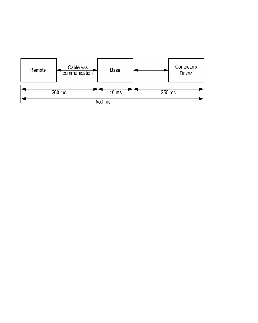
The maximum Process Safety Time (PST) of STOP function is 550 ms according to IEC 60204-32
Ed.2 §9.2.7.3. This PST of 550 ms is taken into account for all safety functions. The PST allocation
is:
So 250 ms are allocated for contactors / drives of the hoisting system. The rest (300 ms) is
allocated for Wireless Remote Control System. In consequences, the maximum response time of
the Wireless Remote Control System is 300 ms for all safety functions in any configurations.

Safety
EIO0000001505 04/2014 71
Legal RFU (Recommendation for Use)
Overview
According to the machinery directive 2006/42/EC and the amendment - RECOMMENDATION
FOR USE n°CNB/M/11.050 rev02, functional test (automatic or manual) shall be performed within
the following test intervals:
At least every month for PL e with category 3 or category 4 (according to EN ISO 13849-1) or
SIL3 with HFT = 1 (according to EN 62061);
At least every 12 months for PL d with category 3 (according to EN ISO 13849-1) or SIL2 with
HFT = 1 (according to EN 62061).
Safety
72 EIO0000001505 04/2014
Summary of the Reliability Study
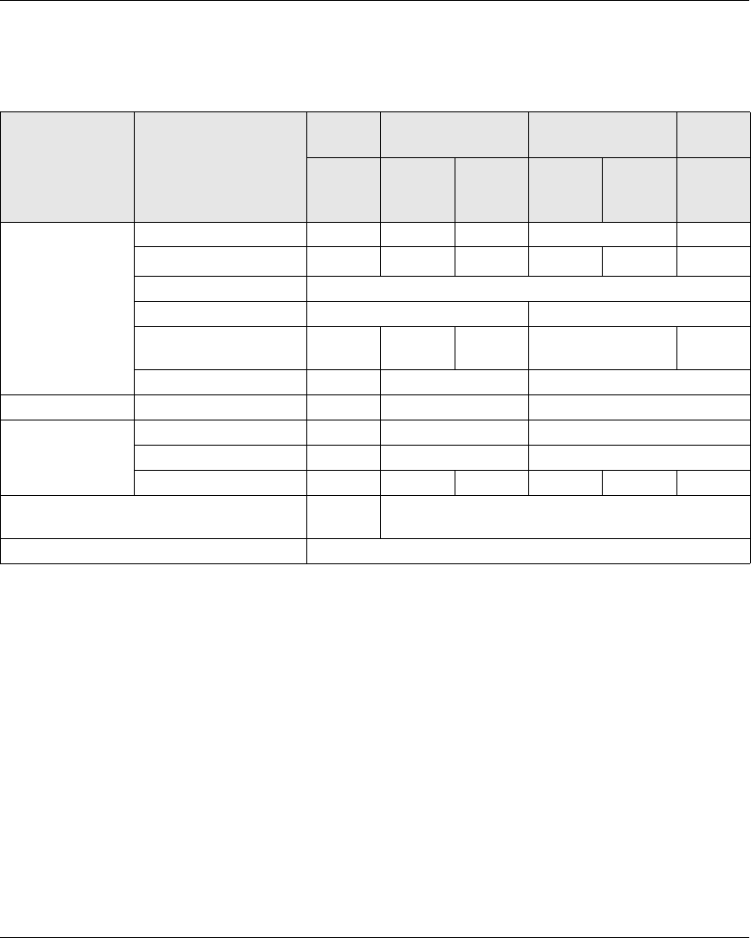
Synthesis of Reliability Study in Configuration 1 Remote Device & 1 Base Station
(1) IEC 62061 standard concerns integration. This standard distinguishes the overall safety
function (classified SIL1, SIL2, or SIL3 according to diagrams in §1.4) from components which
constitute the safety function (classified SIL1 CL, SIL2 CL or SIL3 for eXLhoist).
NOTE: The table above is not sufficient to evaluate the PL of the hoisting system. The PL
evaluation has to be done at the system level. The fitter of the integrator of the eXLhoist has to do
the PL evaluation by including sensors and actuators data numbers from the table above.
SISTEMA software can evaluate the PL of the system.
NOTE: The radio communication of the Wireless Remote Control System is compliant with IEC
61784-3 Ed2 2010.
Synthesis of Reliability Study in Configuration TANDEM 1 Remote Device & 2 Base Station
TANDEM mode will be available on Q4 2014
Standard Safety features E-STOP STOP Standard motion &
auxiliary functions
Limit
switch
With
auxiliary
contact
Without
UOC
UOC Without
UOC
UOC NC
contact
IEC 61508 Ed 2 SFF per channel 97.8 % 85 % 84.8 % 90.1 % 95 %
PFH (10-9 h-1)7.32 7.54 7.57 52.3 51.8 17.9
Type B
HFT 1 0
Diagnostic Coverage per
channel
91.4 % 41.7 % 41.8 % 73.8 % 90 %
SIL capability 3 2 1
IEC 62061 (1) SIL CL capability 3 2 1
ISO 13849-1 2008 PL e d c
Safety category 4 3 2
MTTF in years 15584 15130 15070 2183 2202 6380
Proof test interval (manual functional test) Once per
month
Once per year
Maximum response time 300 ms


Safety
74 EIO0000001505 04/2014
Safety Parameters and Steps to Configure the Safety Functions
Commissioning of Safety Functions
The commissioning type of safety function is:
Some passwords/codes can be configured on the eXLhoist Configuration Software:
E-STOP code sequence on the Remote Device
Start code sequence on the Remote Device
Transfer password:
For the read of the Configuration File in a Remote Device
For the transfer of the Configuration File between a Remote Device and a Base Station.
Functions UOC delay time Relay assignment Remarks
E-STOP - - No commissioning
STOP Yes - Safety relays cannot be
commissioned
Motion & auxiliary functions Yes Yes -
Safeguarding - Yes -
Passwords/codes Default value
E-STOP code sequence -
Start code sequence 5, 6, 5, 6
Transfer password 5, 6, 5, 6

Safety
EIO0000001505 04/2014 75
Machine Signature
Overview
The acceptance test for systems with safety integrated functions focuses on validating the
functionality of safety integrated monitoring and stop functions configured in the Wireless Remote
Control System.
The purpose of the test is to verify proper configuration of the defined safety functions and test
mechanisms and to examine the response of dedicated monitoring functions to explicit input of
values outside the tolerance limits.
The test must cover all Wireless Remote Control System-specific safety configured monitoring
functions and global safety integrated functionality in eXLhoist.
Condition Prior to Acceptance Test
The machine is wired up correctly.
All safety devices such as limit switches, overload sensors, and emergency stop switches are
connected and ready for operation.
All commissioning parameters must be correctly set on the Wireless Remote Control System.
Acceptance Test Process
Step Action Comment
1 Select the Base Station and the Remote Device With the eXLhoist Configuration Software
2 Configure the relay assignments by functions.
3 Configure the interlocking assignments (optional)
4 Define passwords (optional):
E-STOP
STOP
Configuration
Configure:
Timeout
UOC delay
Motion enable / limit switch
5 Select the Microsoft® Excel acceptance test
template file in www.schneider-electric.com.
Complete the acceptance test template according to
the system specificities.
Mark down the configuration signature thanks to the
eXLhoist Configuration Software.
With Microsoft® Excel
The acceptance test template is a generic
acceptance test for generic application. The
acceptance report must be updated according
to the system application.
The signature allows you to compare the
checksum value with the one displayed in the
identification menu on the graphic display.

Safety
76 EIO0000001505 04/2014
Acceptance Report
eXLhoist Configuration Software and Microsoft® Excel are required to create the acceptance
report.
The acceptance report is the safety signature of the Wireless Remote Control System. The
acceptance report provides a final private report when the Wireless Remote Control System has
been configured as Safe and declared Safe during operation. This report is deemed to be a
machine signature and certifies that all the safety functions are operational.
If the system configuration is modified, you must repeat the acceptance test.
6 Test the system according to the acceptance test
Notify the result of the test in the acceptance result.
The acceptance test list becomes the
acceptance result once it fulfills with test
results.
7 Print, save, and sign the acceptance report. -
Step Action Comment


Safety
78 EIO0000001505 04/2014
Maintenance
E-STOP
By way of preventive maintenance and according to the Recommendation For Use (see page 71),
the E-STOP and the STOP function must be activated at least once a month. The Remote Device
and the Base Station must be turned off and then on again before carrying out this preventive
maintenance.
Others Safety Functions
By way of preventive maintenance and according to the Recommendation For Use (see page 71),
the STOP, motion, auxiliary, limit switch functions must be activated at least once a year. The
Remote Device and the Base Station must be turned off and then on again before carrying out this
preventive maintenance.

Safety
EIO0000001505 04/2014 79
Base Station or Remote Device Replacement
Overview
You can replace the Base Station part and the Remote Device part.
If you replace the Base Station or the Remote Device configured in Single, you will not lose your
safety configuration thanks to the maintenance / device replacement procedure but you need to
repeat the acceptance test to avoid incorrect wiring or incorrect behavior of the safety function.
If you replace the Base Station or the Remote Device configured in Tandem, you will lose your
safety configuration. You need to reinstall your configuration on the new Base Station or Remote
Device and then repeat the acceptance test to avoid incorrect wiring or incorrect behavior of the
safety function.
NOTE: For more product information, see the Maintenance / Device Replacement (see page 201).


EIO0000001505 04/2014 81
Harmony eXLhoist
Installation and Wiring
EIO0000001505 04/2014
Installation and Wiring
Chapter 4
Installation and Wiring
What Is in This Chapter?
This chapter contains the following sections:
Section Topic Page
4.1 Base Station Installation 82
4.2 Base Station Wiring 86
4.3 Functionalities Description 98
4.4 Remote Device Installation 112
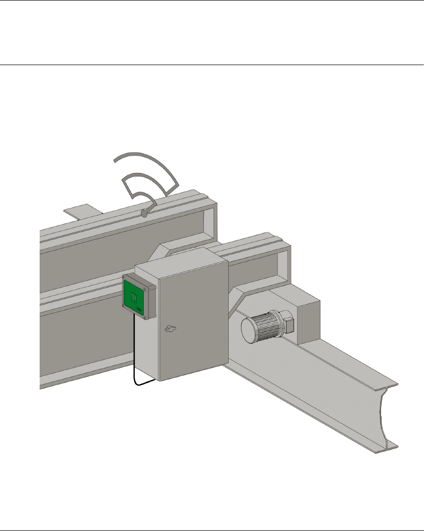
Installation and Wiring
82 EIO0000001505 04/2014
Base Stat ion Installation
Section 4.1
Base Station Installation
Base Station Installation Precaution
Installation Precaution
Example of a recommended Base Station location:
Base Station location:
The Base Station must be installed vertical, with the cable at the bottom.
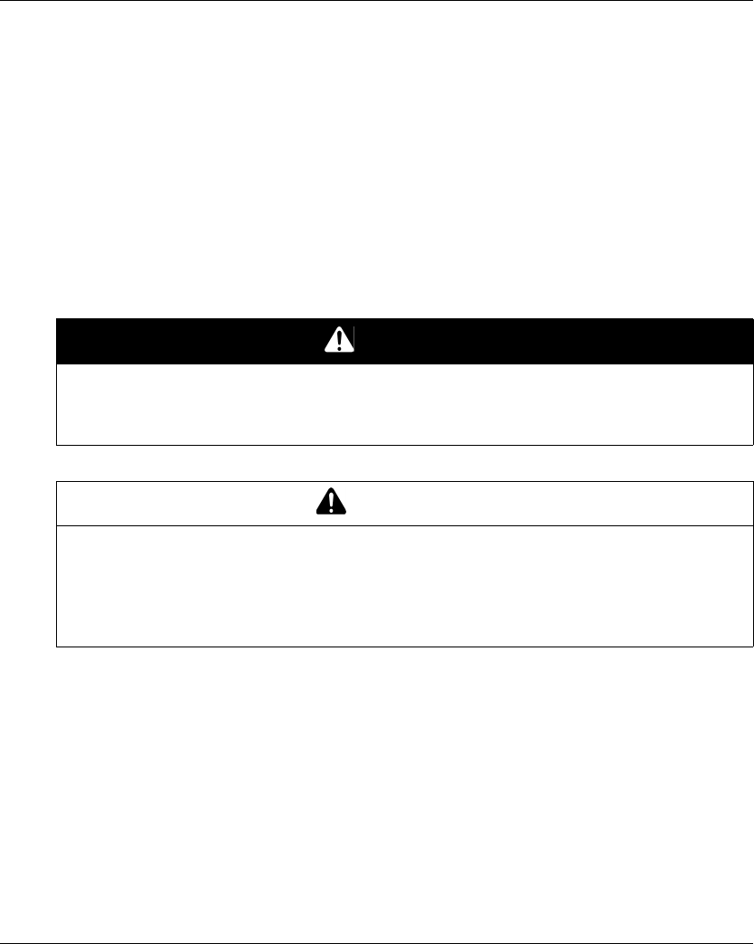
Installation and Wiring
EIO0000001505 04/2014 83
Consider the wiring limitation and the radio communication limitation to choose the Base Station
location.
Do not create obstacle between the Base Station and the Remote Device to optimize the radio
communication level.
The Base Station must not be installed inside closed metal containers.
To prevent communication perturbation:
Do not place cables or metallic parts in front of the Base Station cover.
Do not place obstacles between the Base Station and the Remote Device.
According to IEC 61010-1, it is recommended to install the power switch of the Base Station close
to the Base Station.
To be compliant with IEC 61508, EN 62061 and EN ISO 13849, terminal ferrule must be used for
the output wiring of the ZARB•W
DANGER
HEAVY LOAD MOVING HAZARD
The working range must be free of people when the hoisting system is operating.
Failure to follow these instructions will result in death or serious injury.
WARNING
UNINTENDED EQUIPMENT OPERATION
Install and operate this equipment according to the environmental conditions described in the
operating limits.
Failure to follow these instructions can result in death, serious injury, or equipment
damage.
Installation and Wiring
84 EIO0000001505 04/2014
Installation
WARNING
UNINTENDED EQUIPMENT OPERATION
Use appropriate safety interlocks where personnel and/or equipment hazards exist.
Use the sensor and actuator power supplies only for supplying power to the sensors or
actuators connected to the device.
Power line must be wired and protected with fuse or thermal magnetic switch (ex: Schneider-
Electric GV2) in compliance with local and national regulatory requirements for the rated
current and voltage of the particular equipment.
Do not disassemble, repair, or modify this equipment.
Failure to follow these instructions can result in death, serious injury, or equipment
damage.
Step Action
1 Unscrew the 4 screws at the bottom of the Base Station.
2 Remove the cover.
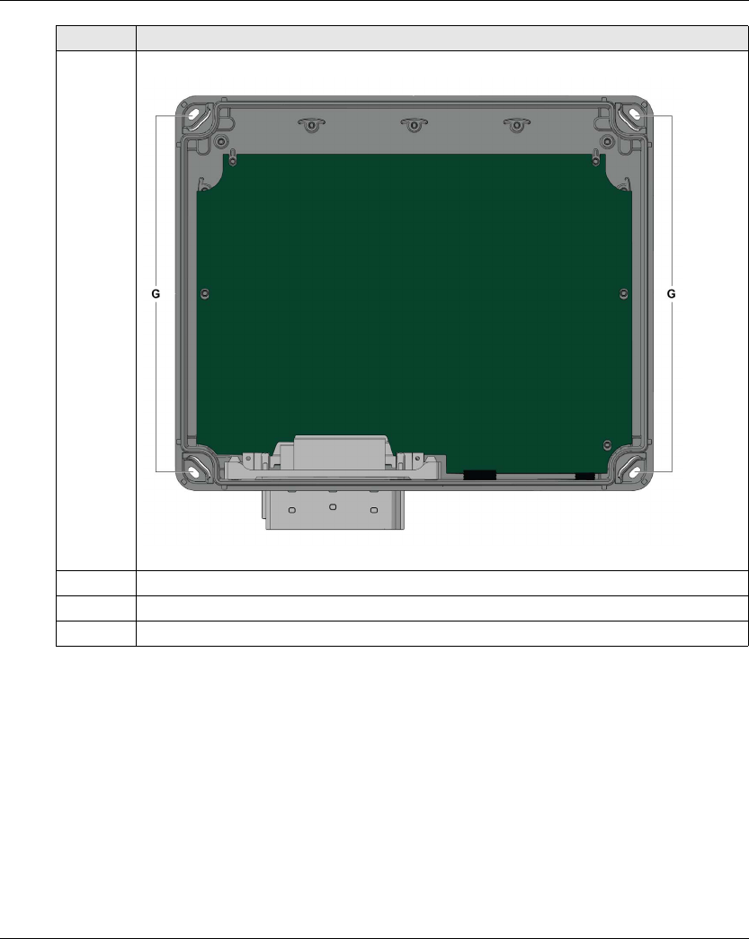
Installation and Wiring
EIO0000001505 04/2014 85
Use the ZARC09 silent blocs in case of applications with severe vibration constraints.
3 Introduce the 4 screws in the dedicated holes (legend G):
4 Screw the 4 mounting screws.
5 Install the Base Station cover.
6 Screw the 4 screws to fasten the Base Station cover.
Step Action

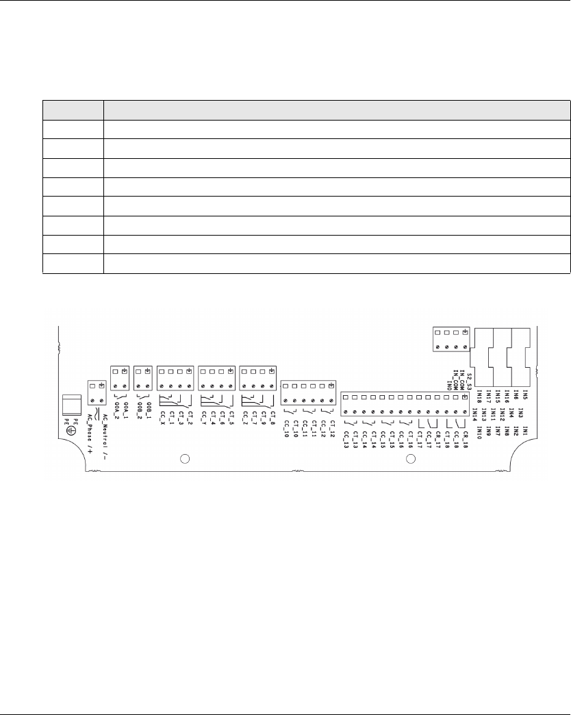
Installation and Wiring
EIO0000001505 04/2014 87
Base Station Wiring
ZARB•W
Wiring procedure:
ZARB18 terminals:
Insulation:
The group of relays (Q1…Q3), (Q4…Q6), (Q7…Q9), (Q10…Q12) and (Q13…Q18), as well as the
group of inputs (IN0…IN18) and the group of power supply (AC_Phase/+, AC_Neutral/-) respect a
SELV insulation between each other.
A single 240 V insulation shall be respected inside each of the following groups: (AC_Phase/+,
AC_Neutral/-),(Q1…Q3), (Q4…Q6), (Q7…Q9), (Q10…Q12) and (Q13…Q18).
A single 24 V insulation shall be respected inside the (IN0…IN18) group.
Step Action
1 Unscrew the 4 screws at the bottom of the Base Station.
2 Remove the cover and insert a cable gland.
3 Remove the caps.
4 Introduce the cable through the Base Station dedicated hole.
5 Connect the wires in the dedicated connectors.
6 Screw the cable gland.
7 Install the Base Station cover.
8 Screw the 4 screws to fasten the Base Station cover.
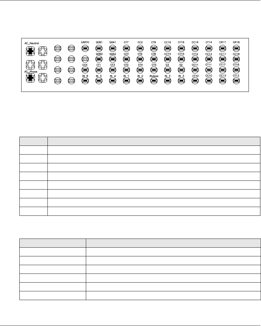
Installation and Wiring
88 EIO0000001505 04/2014
ZARB•H
The input/output are wired to the connector (except the safeguarding inputs).
To connect the Base Station, respect the connector description:
If the ZARC03 external antenna is used, refer to the dedicated Instruction Sheet (seepage9).
Safeguarding Inputs
Safeguarding inputs wiring procedure:
Input/Output Possible Uses
Step Action
1 Unscrew the 4 screws at the bottom of the Base Station.
2 Remove the cover and insert a cable gland.
3 Remove the caps of cable gland.
4 Introduce the cable through the Base Station dedicated hole.
5 Connect the wires in the dedicated terminals.
6 Screw the cable gland.
7 Install the Base Station cover.
8 Screw the 4 screws to fasten the Base Station cover.
Input/Output Possible uses (Depending of the configuration)
IN0 Safety loop input (see page 111)
IN1…IN6 Detected Applicative Alarm (see page 103)
IN7…IN18 Safeguarding (see page 107)
S2_S3 Terminals for SIL2 / SIL3 E-STOP Configuration (see page 111)
Q0A, Q0B Safety relay (see page 111)
Q1…Q9 Motion relays (see page 99)
Installation and Wiring
EIO0000001505 04/2014 89
Power Supply
Protective Earth Ground
The electrical isolation of the Base Station power supply from machine ground could cause static
electricity damages. The limit switch could unintended operates in case of ground fault.
The equipment could non-stop in case of ground fault detections on any control circuits.
Factory Setting
For details on factory setting (wiring and configuration), refer to factory setting description
(seepage94).
Q10…Q16 (NO type)
Q17, Q18 (NO+NC type)
Auxiliary relays (see page 99)
Selector (seepage102)
UOC (see page 105)
Specific relays (see page 109)
Input/Output Possible uses (Depending of the configuration)
NOTICE
INOPERABLE EQUIPMENT
The ZARB•H Base Station must be powered with a voltage:
From 24 Vac -15% to 48 Vac +10% with frequency of 50 Hz -6%/+4% and frequency of 60 Hz
-6%/+4%.
From 24 Vdc -15% to 48 Vdc +20%.
The ZARB•W Base Station must be powered with a voltage:
From 24 Vac -15% to 240 Vac +10% with frequency of 50 Hz -6%/+4% and frequency of
60 Hz -6%/+4%.
From 24 Vdc -15% to 240 Vdc +20%.
Failure to follow these instructions can result in equipment damage.
WARNING
UNINTENDED EQUIPMENT OPERATION
Connect the Base Station protective earth ground connection to the machine ground.
Failure to follow these instructions can result in death, serious injury, or equipment
damage.

Installation and Wiring
EIO0000001505 04/2014 91
Wiring Best Practices
Overview
This section describes the wiring guidelines and associated best practices to be respected when
using the system.
1 For additional information, refer to NEMA ICS 1.1 (latest edition), "Safety Guidelines for the
Application, Installation, and Maintenance of Solid State Control" and to NEMA ICS 7.1 (latest
edition), "Safety Standards for Construction and Guide for Selection, Installation, and Operation of
Adjustable-Speed Drive Systems" or their equivalent governing your particular location.
DANGER
HAZARD OF ELECTRIC SHOCK, EXPLOSION OR ARC FLASH
Disconnect all power from all equipment including connected devices prior to removing any
covers or doors, or installing or removing any accessories, hardware, cables, or wires except
under the specific conditions specified in the appropriate hardware guide for this equipment.
Always use a properly rated voltage sensing device to confirm that the power is off where and
when indicated.
Replace and secure all covers, accessories, hardware, cables, and wires and confirm that a
proper ground connection exists before applying power to the unit.
Use only the specified voltage when operating this equipment and any associated products.
Failure to follow these instructions will result in death or serious injury.
WARNING
LOSS OF CONTROL
The designer of any control wiring diagram must consider the potential failure modes of control
paths and, for certain critical control functions, provide a means to achieve a safe state during
and after a path failure. Examples of critical control functions are emergency stop and
overtravel stop, power outage and restart.
Separate or redundant control paths must be provided for critical control functions.
System control paths may include communication links. Consideration must be given to the
implications of unanticipated transmission delays or failures of the link.
Observe all accident prevention regulations and local safety guidelines.1
Each implementation of this equipment must be individually and thoroughly tested for proper
operation before being placed into service.
Failure to follow these instructions can result in death, serious injury, or equipment
damage.
Installation and Wiring
92 EIO0000001505 04/2014
Protective Ground (PE) on the Backplane
The protective ground (PE) is connected to the conductive backplane by a heavy-duty wire, usually
a braided copper cable with the maximum allowable cable section.
1Multipoint grounding is permissible if connections are made to an equipotential ground plane
dimensioned to help avoid cable shield damage in the event of power system short-circuit currents
Wiring Guidelines
The following rules must be applied when wiring the system:
I/O wiring must be kept separate from the power wiring. Route these 2 types of wiring in
separate cable ducting.
Verify that the operating conditions and environment are within the specification values.
Use proper wire sizes to meet voltage and current requirements.
Use copper conductors (highly recommended).
Use twisted pair, shielded cables.
WARNING
IMPROPER GROUNDING CAN CAUSE UNINTENDED EQUIPMENT OPERATION
Use cables with insulated shielded jackets for I/O signals.
Ground shielded cables for I/O signals at a single point 1.
Always comply with local wiring requirements regarding grounding of cable shields.
Failure to follow these instructions can result in death, serious injury, or equipment
damage.
WARNING
UNINTENDED EQUIPMENT OPERATION
Use shielded cables wherever specified for inputs and outputs connections.
Properly ground the cable shields as indicated in the related documentation.
Route I/O cables separately from power cables.
Failure to follow these instructions can result in death, serious injury, or equipment
damage.
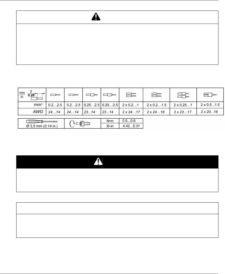
Installation and Wiring
EIO0000001505 04/2014 93
Rules for Screw Terminal Block
The following tables show the cable types and wire sizes for a 5.08 mm pitch screw terminal block:
The use of copper conductors is required.
The use of cable ends is required.
WARNING
UNINTENDED EQUIPMENT OPERATION
Power line must be wired and protected with fuse or thermal magnetic switch (ex: Schneider-
Electric GV2) in compliance with local and national regulatory requirements for the rated current
and voltage of the particular equipment.
Failure to follow these instructions can result in death, serious injury, or equipment
damage.
DANGER
FIRE HAZARD
Use only the recommended wire sizes for I/O channels and power supplies.
Failure to follow these instructions will result in death or serious injury.
NOTICE
INOPERABLE EQUIPMENT
Do not tighten screw terminals beyond the specified maximum torque (Nm / lb-in.).
Failure to follow these instructions can result in equipment damage.

Installation and Wiring
94 EIO0000001505 04/2014
Factory Setting Description
General Parameters
Detected Applicative Alarms
Base Station wiring:
Safeguarding function (only for ZARB18•)
Base Station wiring:
General Label Factory setting value
Parameter Start access sequence (see page 192)Enable: 5, 6, 5, 6
E-STOP RESET sequence (see page 192)Disable
Standby Time-out (see page 193)15 minutes
Power saving Time-out (seepage193)15 minutes
Horn duration (see page 193)2 seconds
Protection Configuration File Transfer Password (see page 183)Enable: 5, 6, 5, 6
Label Wiring description Factory setting description
IN1 Sensor input Overload pre-alarm
IN2 Sensor input Overload alarm
IN3 Sensor input Over wind pre-alarm
IN4 Sensor input Over wind alarm
IN5 Sensor input Over speed alarm
IN6 Sensor input Generic alarm
IN_COM Common output port (to be connected to the other side of
the dry contact connected to the IN1…IN6 inputs)
-
Label Wiring description Factory setting description
IN7 Limit switch input (for button 1) When IN7 is activated, the relay 1 is OFF
IN8 Limit switch input (for button 1H) When IN8 is activated, the relays 1 and 3 are OFF
IN9 Limit switch input (for button 2) When IN9 is activated, the relay 2 is OFF
IN10 Limit switch input (for button 2H) When IN10 is activated, the relays 2 and 3 are OFF
IN11 Limit switch input (for button 3) When IN11 is activated, the relay 4 is OFF
IN12 Limit switch input (for button 3H) When IN12 is activated, the relays 4 and 6 are OFF
IN13 Limit switch input (for button 4) When IN13 is activated, the relay 5 is OFF
IN14 Limit switch input (for button 4H) When IN14 is activated, the relays 5 and 6 are OFF

Installation and Wiring
EIO0000001505 04/2014 95
Motion Relays
Base Station wiring:
IN15 Limit switch input (for button 5) When IN15 is activated, the relay 7 is OFF
IN16 Limit switch input (for button 5 +7) When IN16 is activated, the relays 7 and 9 are OFF
IN17 Limit switch input (for button 6) When IN17 is ON, the relay 8 is OFF
IN18 Limit switch input (for button 6 +7) When IN18 is ON, the relays 8 and 9 are OFF
IN_COM Common output port (to be
connected to the other side of the
dry contact connected to the
IN7…IN18 inputs)
-
Label Wiring description Factory setting description
Label Wiring description Factory setting description
Motion relays (for motor axis X)
CC_X Common for relays 1…3 -
CT_1 Output of motion relay 1 Command for motion direction 1
Relay is ON when button 1 or 1H is pressed
CT_2 Output of motion relay 2 Command for motion direction 2
Relay is ON when button 2 or 2H is pressed
CT_3 Output of motion relay 3 Command for high speed
Relay is ON when button 1H or 2H is pressed
Motion relays (for motor axis Y)
CC_Y Common for relays 4…6 -
CT_4 Output of motion relay 4 Command for motion direction 1
Relay is ON when button 3 or 3H is pressed
CT_5 Output of motion relay 5 Command for motion direction 2
Relay is ON when button 4 or 4H is pressed
CT_6 Output of motion relay 6 Command for high speed
Relay is ON when button 3H or 4H is pressed
Motion relays (for motor axis Z)
CC_Z Common for relays 7…9 -
CT_7 Output of motion relay 7 Command for motion direction 1
Relay is ON when button 5 or 5+7 is pressed
CT_8 Output of motion relay 8 Command for motion direction 2
Relay is ON when button 6 or 6+7 is pressed
CT_9 Output of motion relay 9 Command for high speed
Relay is ON when button 5+7 or 6+7 is pressed

Installation and Wiring
96 EIO0000001505 04/2014
Auxiliary Relays
Base Station wiring:
The description of the relays 13 to 18 depends on the Base Station and Remote Device;
Base Station:
General Label Wiring description Factory setting description
Auxiliary relay 10 CC_10 Common Selector
Relay 10 is ON when the Selector (button 10) is
in position 1 or 1+2
Relay 11 is ON when the Selector (button 10) is
in position 2 or 1+2
CT_10 Output (NO type)
Auxiliary relay 11 CC_11 Common
CT_11 Output (NO type)
Auxiliary relay 12 CC_12 Common “Horn” relay
Relay is ON during the start procedure, and for
a configurable duration.
In START mode, the relay is ON as long as the
ON/START/Horn button is pressed.
CT_12 Output (NO type)
Auxiliary relay 13 CC_13 Common “Radio link” relay
Relay 13 is ON as long as the radio
communication is achieved between the Base
Station and its Remote Device.
CT_13 Output (NO type)
Auxiliary relay 14 CC_14 Common Relay 14 is ON when button 11 is pressed
CT_14 Output (NO type)
Auxiliary relay 15 CC_15 Common Relay 15 is ON when button 12 is pressed
CT_15 Output (NO type)
Auxiliary relay 16 CC_16 Common Relay 16 is ON when button 13 is pressed
CT_16 Output (NO type)
Auxiliary relay 17 CC_17 Common Relay 17 is ON when button 14 is pressed
CT_17 Output (NO type)
CR_17 Output (NC type)
Auxiliary relay 18 CC_18 Common Relay 18 is ON when button 15 is pressed
CT_18 Output (NO type)
CR_18 Output (NC type)
References ZARB12• ZARB18•
Motion & auxiliary standard
relays
12 (Q1…Q12) 18 (Q1…Q18)
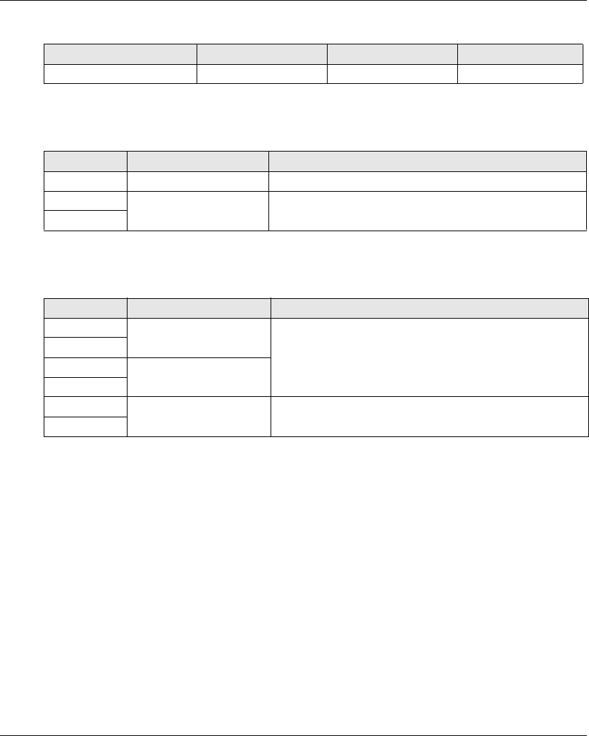
Installation and Wiring
EIO0000001505 04/2014 97
Remote Device:
Power Supply and PE
Base Station wiring:
Safety
Base Station wiring:
References ZART8L ZART8D ZARB12•
Number of buttons 11 (8 configurable) 11 (8 configurable) 15 (12 configurable)
Label Wiring description Factory setting description
PE Protected earth ground -
AC_Neutral /- Base Station power supply -
AC_Phase /+
Label Wiring description Factory setting description
Q0A_1 Safety relay 1 -
Q0A_2
Q0B_1 Safety relay 2
Q0B_2
IN0 Safety loop -
S2_S3

Installation and Wiring
98 EIO0000001505 04/2014
Functionalities Des cription
Section 4.3
Functionalities Description
What Is in This Section?
This section contains the following topics:
Topic Page
Motion/Auxiliary Relays 99
Selector 102
Detected Applicative Alarm 103
Unintended Operating Control (UOC) Function 105
Safeguarding Function 107
Special Functions 109
Safety Relay 111
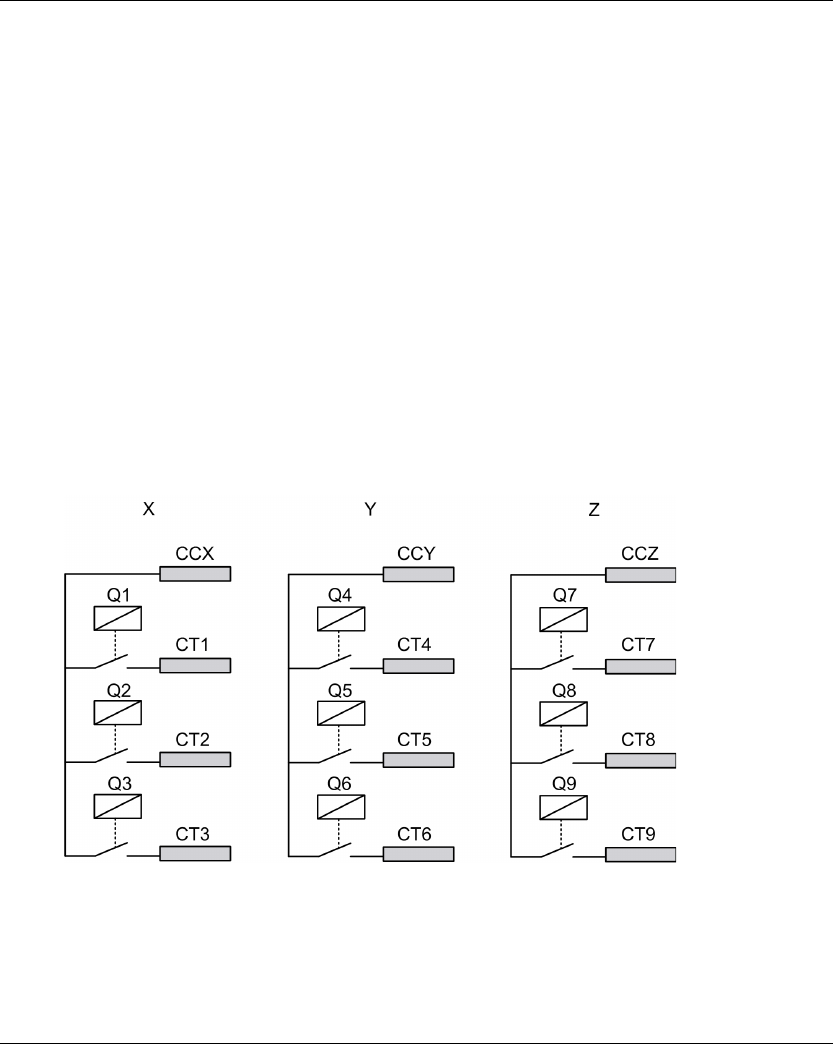
Installation and Wiring
EIO0000001505 04/2014 99
Motion/Auxiliary Relays
Description
The motion/auxiliary relays are switched ON as long as the associated button is pressed.
Only up to 6 motion/auxiliary relays activation occurs at the same time.
If more than 6 motion/auxiliary relays switching are requested at the same time, then they are
actuated in successive switching every 20 ms (except for UOC relays).
You can configure the motion/auxiliary relays with the eXLhoist Configuration Software
(seepage194).
General Wiring Rules
The I/O and power supply cables should be AWG 16 (cross-sectional conductor area = 1.3 mm2).
The I/O and power supply cable lengths should not exceed 20 m (65.6 ft).
For more details, refer to Wiring Best Practices (see page 91).
Wiring
Q1…Q9 motion relay internal wiring (NO type):
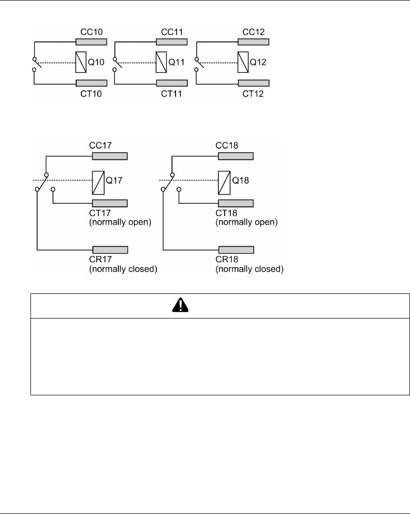
Installation and Wiring
100 EIO0000001505 04/2014
Q10…Q16 motion/auxiliary relay wiring (NO type only)
Q17, Q18 auxiliary relay wiring (NO+NC type)
Motion Wiring
For wiring examples, refer to the Architecture examples (seepage216).
The motion/auxiliary relays output cable length should not exceed 20 m (65.6 ft).
WARNING
UNINTENDED EQUIPMENT OPERATION
Power line must be wired and protected with fuse or thermal magnetic switch (ex: Schneider-
Electric GV2) in compliance with local and national regulatory requirements for the rated current
and voltage of the particular equipment.
Failure to follow these instructions can result in death, serious injury, or equipment
damage.

Installation and Wiring
EIO0000001505 04/2014 101
Auxiliary Wiring
The auxiliary buttons can be used, for example, to manage a:
Vacuum/magnetic function (see page 221)
Room lighting function (see page 224)
Selector switch function (see page 102)
Supplementary motion
The motion/auxiliary relays output cable length should not exceed 20 m (65.6 ft).
Factory Setting
For details on factory setting (wiring and configuration), refer to factory setting description
(seepage94).

Installation and Wiring
102 EIO0000001505 04/2014
Selector
Description
In SINGLE configuration, the Selector button is associated to 2 relays.
With an adapted wiring, these relays enable/disable the motions of the selected device
(hook/trolleys).
In TANDEM configuration, no relays are associated with the selector button. The button is used to
select directly which Base Station are piloted.
You can configure the selector with the eXLhoist Configuration Software (see page 194).
General Wiring Rules
The I/O and power supply cables should be AWG 16 (cross-sectional conductor area = 1.3 mm2).
The I/O and power supply cable lengths should not exceed 20 m (65.6 ft).
For more details, refer to Wiring Best Practices (see page 91).

Installation and Wiring
EIO0000001505 04/2014 103
Detected Applicative Alarm
Overview
The ZARB18• Base Station implements 6 inputs: IN1…IN6.
Different sensors can be connected to these inputs.
These inputs are dedicated for applicative alarms.
Description
The detected applicative alarms are only displayed on the ZART•D Remote Device.
Factory settings:
You can configure the detected applicative alarm inputs with the eXLhoist Configuration Software
(seepage199).
General Wiring Rules
The I/O and power supply cables should be AWG 16 (cross-sectional conductor area = 1.3 mm2).
The I/O and power supply cable lengths should not exceed 20 m (65.6 ft).
For more details, refer to Wiring Best Practices (see page 91).
Input Description
IN1 Overload pre-alarm
IN2 Overload alarm
IN3 Over wind pre-alarm
IN4 Over wind alarm
IN5 Over speed alarm
IN6 Generic alarm
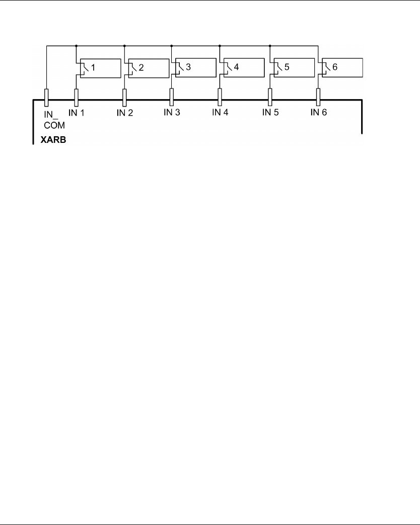
Installation and Wiring
104 EIO0000001505 04/2014
Wiring
Wiring diagram for the detected applicative alarm devices:
1-6 Detected applicative alarm sensors
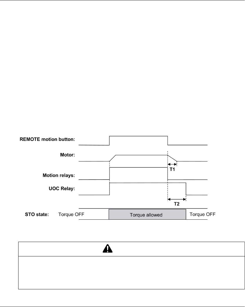
Installation and Wiring
EIO0000001505 04/2014 105
Unintended Operating Control (UOC) Function
Overview
The Base Station can manage 3 UOC functions.
These relays have temporization that shall correspond to the decelerating time ramp of the drive.
After this time, the UOC relay will switch OFF to enable the Safe Torque Off (STO according to EN
IEC 61500-5-2) input on the drive.
The UOC function allows the Wireless Remote Control System to get a STOP category 1 according
to EN60204.
Description
A UOC relay is associated to one motion axis (4 motion buttons).
Once a motion button is pressed, the associated UOC relay is switched ON.
When all motion buttons are released, the UOC delay time starts.
The UOC relay is switched OFF after the UOC pre-defined delay.
UOC function diagram with a drive (the UOC relay is normally open (NO)):
T1 Drive deceleration time.
T2 UOC delay time.
You can configure the UOC with the eXLhoist Configuration Software (seepage194).
WARNING
UNINTENDED EQUIPMENT OPERATION
The UOC delay time must be longer than the drive deceleration time.
Failure to follow these instructions can result in death, serious injury, or equipment
damage.

Installation and Wiring
106 EIO0000001505 04/2014
General Wiring Rules
The I/O and power supply cables should be AWG 16 (cross-sectional conductor area = 1.3 mm2).
The I/O and power supply cable lengths should not exceed 20 m (65.6 ft).
For more details, refer to Wiring Best Practices (see page 91).
Wiring
Depending on the DRIVE functionality and its application schematic, the UOC relay can be directly
connected to the DRIVE Safe Torque Off (STO according to EN/IEC 61500-5-2) input or in serial
with a contactor coil.
For wiring examples, refer to the Architecture examples (seepage216).
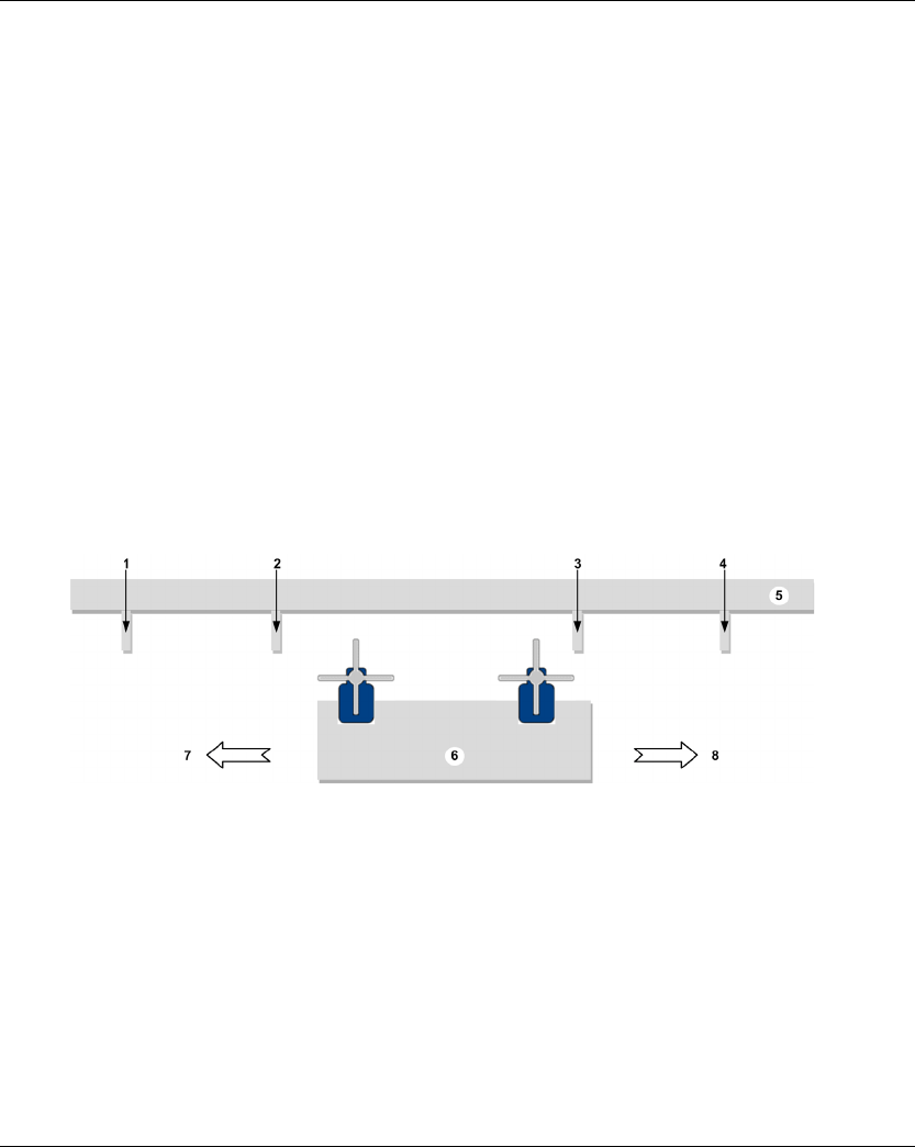
Installation and Wiring
EIO0000001505 04/2014 107
Safeguarding Function
Overview
The ZARB18• Base Station implement 12 inputs IN7…IN18.
These inputs are dedicated for limit switches to provide a protection to the hoist system.
Description
There are 4 limit switches per axis that allow to:
Stop the motion at minimum mechanical position.
Disable the high speed of the direction when the hoist system is near the minimum position.
Stop the motion at maximum mechanical position.
Disable the high speed of the direction when the hoist system is near the maximum position.
These inputs are associated to motion buttons.
Once a limit switch is opened, the associated motion relay(s) is(are) switched OFF.
You can configure the limit switches with the eXLhoist Configuration Software (see page 194).
Installation Principle
Principle of safeguarding function installation for 1 axis:
1 Mechanical target for limit switch triggering for stopping the motion direction
2 Mechanical target for limit switch triggering for slowing the motion direction
3 Mechanical target for limit switch triggering for slowing the motion direction
4 Mechanical target for limit switch triggering for stopping the motion direction
5 Stationary part
6 Mobil part
7 Motion (example: button 1 or 1H)
8 Motion (example: button 2 or 2H)
General Wiring Rules
The I/O and power supply cables should be AWG 16 (cross-sectional conductor area = 1.3 mm2).
The I/O and power supply cable lengths should not exceed 20 m (65.6 ft).
For more details, refer to Wiring Best Practices (see page 91).
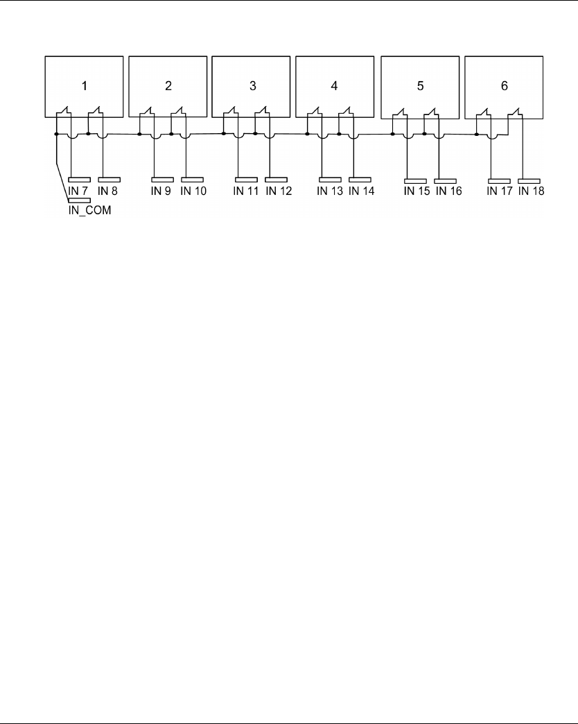
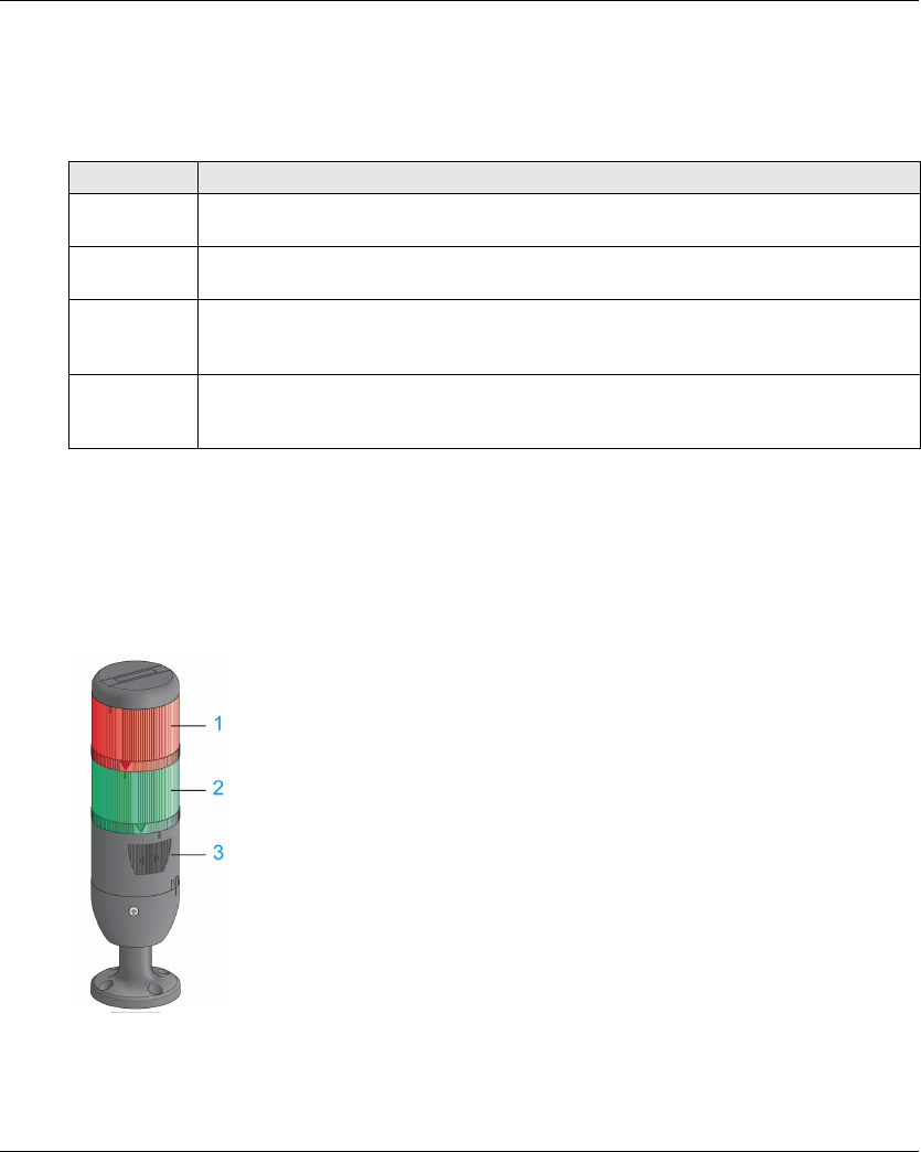
Installation and Wiring
EIO0000001505 04/2014 109
Special Functions
Description
The Wireless Remote Control System manages 4 specific relays:
You can configure the specific relays with the eXLhoist Configuration Software (see page 194).
Application Example
A “Radio link” indication shall inform operator about the system communication status according
to EN 15011 standard.
It is recommended to use a Schneider Electric beacon:
1 Light wired to the “Radio link” relay
2 Light wired to the “Safety relay image” relay
3 Buzzer wired to the “Horn” relay (an additional flash light can be wired to this relay)
The beacon operating is described in the START mode description (see page 125).
Relay Description
Horn This relay is switched ON during the start procedure, and for a configurable duration.
This relay is also switched ON, in START mode, as long as the ON/START/Horn is pressed.
Radio link This relay is switched ON as long as a RADIO communication is achieved between the Base
Station and its Remote Device.
Safety relay
image
This relay is switched ON as long as the 2 safety relays are ON.
It occurs only in START mode and if all the safety conditions are fulfilled.
It can indicate when the motions are enabled.
Tandem 1+2 This relay is switched ON only in TANDEM configuration and only when the 2 Base stations
are selected.
This relay can be used in case of inhibition of anticollision in TANDEM configuration.

Installation and Wiring
110 EIO0000001505 04/2014
General Wiring Rules
The I/O and power supply cables should be AWG 16 (cross-sectional conductor area = 1.3 mm2).
The I/O and power supply cable lengths should not exceed 20 m (65.6 ft).
For more details, refer to Wiring Best Practices (see page 91).
Factory Setting
For details on factory setting (wiring and configuration), refer to factory setting description
(seepage94).

Installation and Wiring
EIO0000001505 04/2014 111
Safety Relay
IN0 Safety Loop Input
The IN0 input is dedicated to check the correct actuator functionality with the auxiliary contact
state.
The E-STOP function can reach up to SIL 3 level only if all the relevant auxiliary contacts are
connected between the IN0 input and the S2_S3 port terminal.
The I/O and power supply cable lengths should not exceed 20 m (65.6 ft).
Q0A/Q0B Safety Relays
The safety relays are switched ON when ON/START/Horn button is activated and all the safety
conditions are fulfilled.
The safety relay output cable length should not exceed 20 m (65.6 ft).
General Wiring Rules
The I/O and power supply cables should be AWG 16 (cross-sectional conductor area = 1.3 mm2).
The I/O and power supply cable lengths should not exceed 20 m (65.6 ft).
For more details, refer to Wiring Best Practices (see page 91).
Wiring
For wiring examples, refer to the Architecture examples (seepage216).
Safety Details
For more details about safety, refer to Safety chapter (seepage53).

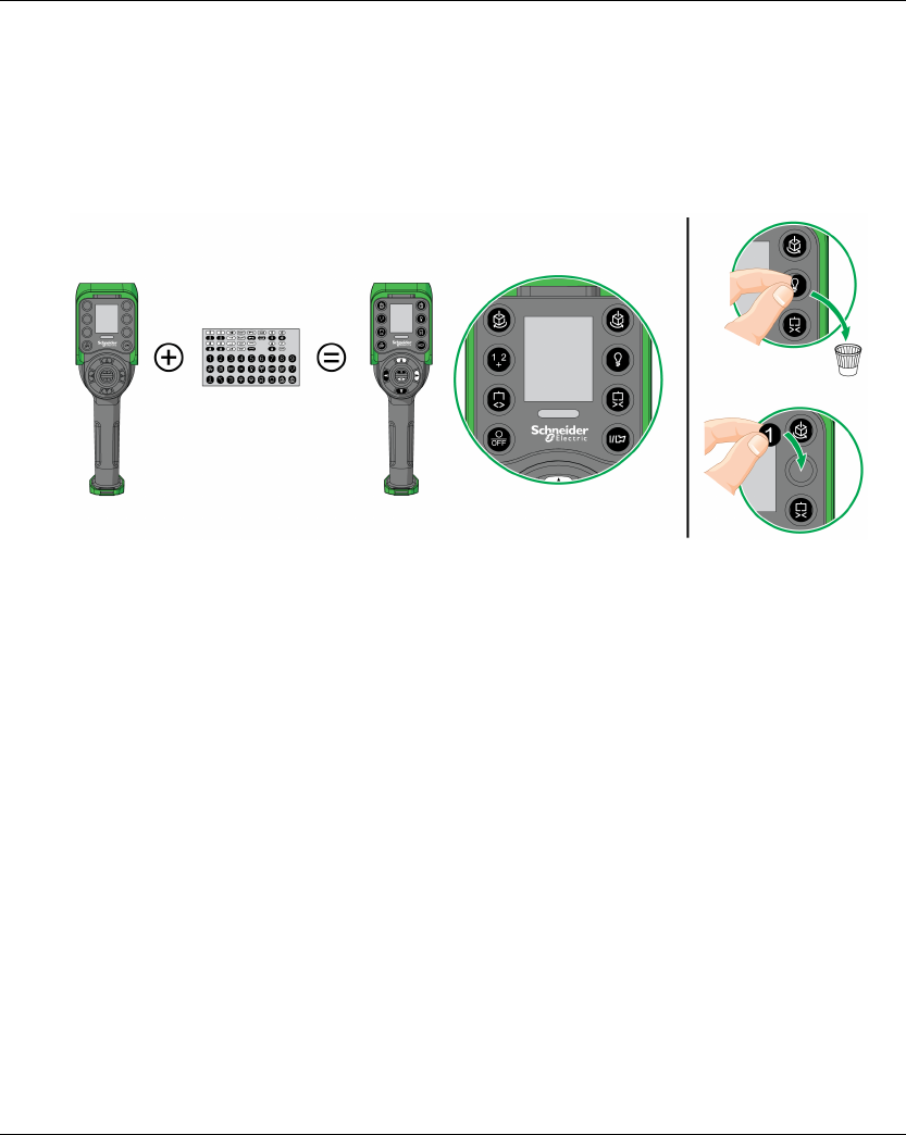
Installation and Wiring
EIO0000001505 04/2014 113
Customize The Remote Device
Overview
The Wireless Remote Control System is delivered with a factory configuration.
Use the label set to customize the remote buttons in accordance with the motion/auxiliary
configuration.
For details on factory setting (wiring and configuration), refer to factory setting description
(seepage94).
You can also stick an empty label above the top side of the Remote Device, and write on it the label
of the hoisting system driven by it.
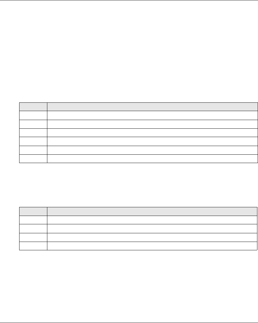
Installation and Wiring
114 EIO0000001505 04/2014
First Commissioning
Overview
The following procedures describe the first commissioning of a Wireless Remote Control System
from a pack (Base Station + Remote Device).
The installation must be in accordance to the factory setting (see page 94).
In other case, refer to eXLhoist Configuration Software (see page 201) and the Discovery
procedure description (seepage137).
First Commissioning with 1 Base Station and the ZART8L
Result: The Wireless Remote Control System is in STOP mode (see page 123).
First Commissioning with 1 Base Station and the ZART•D
Step Action
1 Charge the Remote Device for more than 20 minutes.
2 Install the Base Station.
3 Power ON the Base Station.
4 Place yourself to an appropriate distance from the Base Station (around 10 m (32.8 ft)).
5 Press only the ON/START/Horn button more or equal than 1 s.
6 Wait for the E-STOP LED to be permanently ON.
Step Action
1 Charge the Remote Device for more than 20 minutes.
2 Install the Base Station.
3 Power ON the Base Station.
4 Place yourself to an appropriate distance from the Base Station (around 10 m (32.8 ft)).
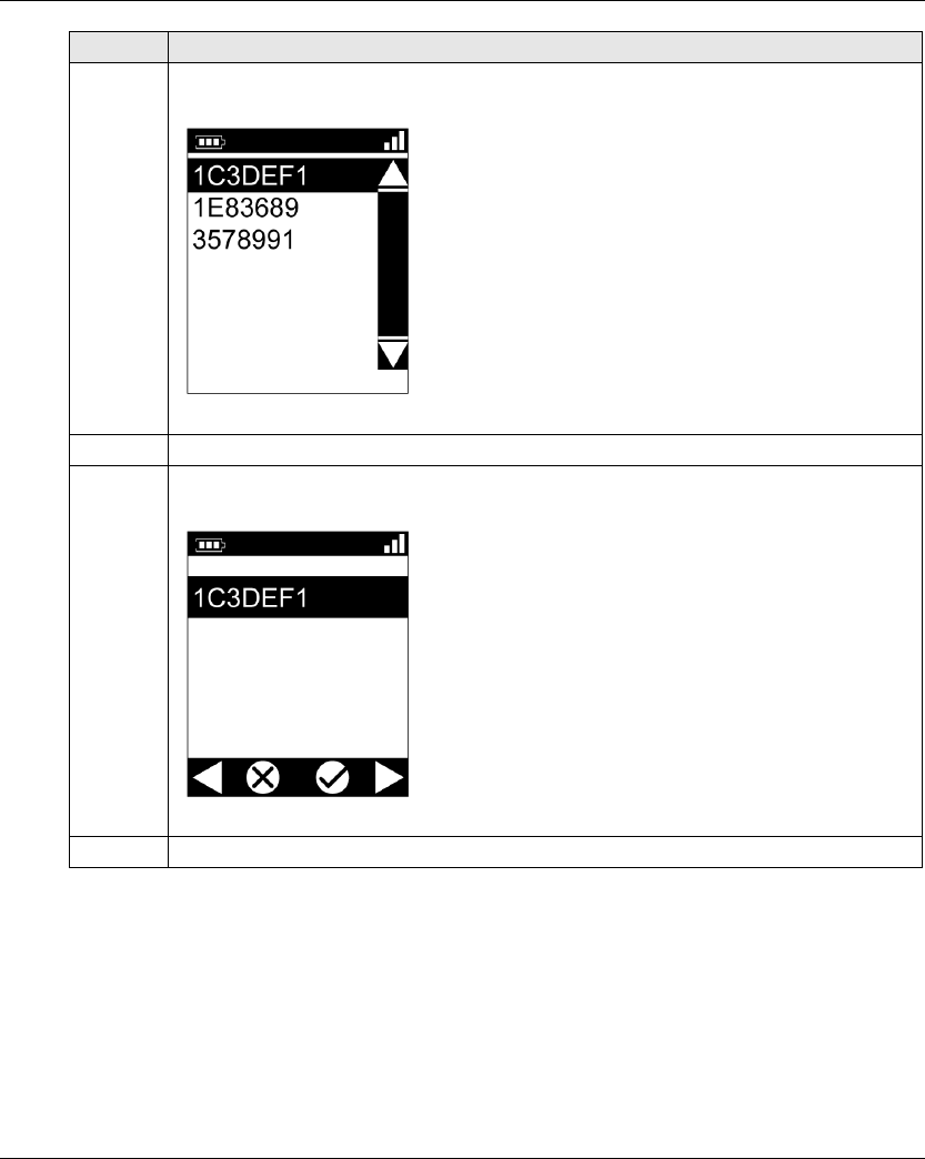
Installation and Wiring
EIO0000001505 04/2014 115
5 Press only the ON/START/Horn button more or equal than 1 s.
Result: The Remote Device displays the ID list of detected Base Station:
6 Selects the ID of the new Base Station with buttons 5 and 6.
7 Press the button 7 (trigger) to validate.
Result:
8 Select the validation cell (check symbol) with buttons 1 and 2.
Step Action
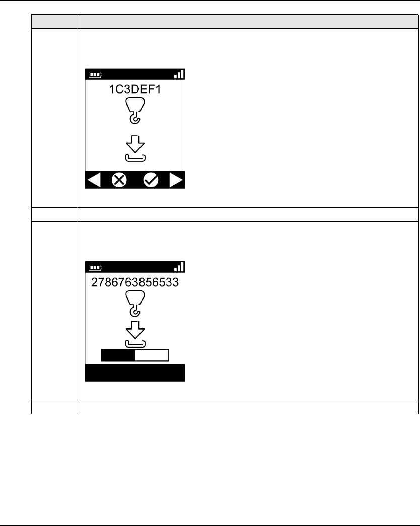
Installation and Wiring
116 EIO0000001505 04/2014
Result: The Wireless Remote Control System is in STOP mode (see page 123).
9 Press the button 7 (trigger) to validate.
Result: The Remote Device proposes to load the Configuration File from the Base Station to
the Remote Device.
10 Select the validation cell (check symbol) with buttons 1 and 2.
11 Press the button 7 (trigger) to validate.
Result: The Remote Device loads the Configuration File from the Base Station to the Remote
Device.
12 Wait for the end of the Configuration File load.
Step Action

EIO0000001505 04/2014 117
Harmony eXLhoist
Using The Wireless Remote Control System
EIO0000001505 04/2014
Using The Wireless Remote Control System
Chapter 5
Using The Wireless Remote Control System
What Is in This Chapter?
This chapter contains the following sections:
Section Topic Page
5.1 Basic Uses 118
5.2 Functionalities 130
5.3 Discovering 137
5.4 How to Modify the Configuration 140
5.5 Remote Device Charge 143

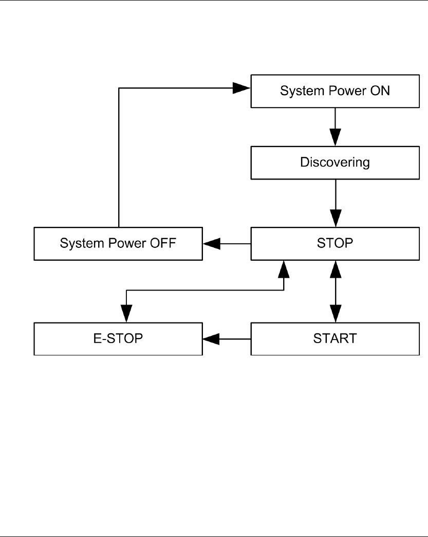
Using The Wireless Remote Control System
EIO0000001505 04/2014 119
Main Modes Diagram
Main Modes Diagram
The following diagram presents the main modes of the Wireless Remote Control System:

Using The Wireless Remote Control System
120 EIO0000001505 04/2014
Power ON
Overview
The aim is to describe how to power ON the Wireless Remote Control System.
Triggering Procedure
Result: The Remote Device is powered ON.
The discovery procedure is automatically launched. If the Wireless Remote Control System has
been installed correctly, the Wireless Remote Control System goes automatically in STOP mode
(seepage123).
In other case, refer to the discovery description (see page 137).
Release
The Remote Device is powered OFF:
By the Power OFF procedure (see page 128).
Automatically when the Remote Device battery level is too low.
Automatically after the Power-saving time-out. You can configure the Power-saving time-out in
the XAR Configuration software (see page 193).
Step Action
1 Check that the Remote Device is powered OFF.
2 Power ON the Base Station.
3 Press only the ON/START/Horn button more or equal than 1 s.
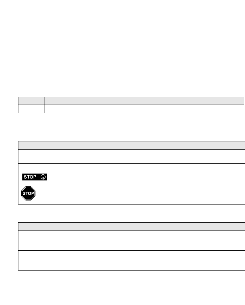
Using The Wireless Remote Control System
EIO0000001505 04/2014 121
E-STOP
Overview
The E-STOP function leads to go to the safe position of the Wireless Remote Control System when
the operator presses the E-STOP red mushroom button.
In E-STOP mode, the motion/auxiliary relays and the safety relays are OFF.
NOTE: The Remote Device cannot go to the E-STOP mode while the E-STOP function is not
operational (E-STOP LED is OFF).
Triggering Procedure
Wireless Remote Control System In E-STOP Mode
Remote Device:
Base Station:
Step Action
1 Press the E-STOP button.
Reference Description
ZART8L The START LED is OFF.
The E-STOP LED is blinking at a frequency of 1 Hz.
ZART•D The STOP mode symbol is displayed.
The E-STOP symbol is permanently displayed.
The E-STOP LED is blinking at a frequency of 1 Hz.
The Remote Device generate a vibration for 3 seconds and generate the same thing
every 10 min until the E-STOP mode is released.
Reference Description
Relays The safety relays are OFF.
The motion/auxiliary relays are OFF.
The “Safety relay image” relay is OFF.
LEDs The STATUS LED is blinking.
The POWER LED is ON.
The COM LED is blinking.

Using The Wireless Remote Control System
122 EIO0000001505 04/2014
Release
Release procedure:
Result: The Wireless Remote Control System is in STOP mode (see page 123).
Specifics Information
You can configure the E-STOP restart code sequence in the eXLhoist Configuration Software
(seepage191).
Step Action
1 Verify that there is no more risk conditions.
2 Release the E-STOP button.
3 If an E-STOP restart code sequence is configured:
Type the E-STOP restart code sequence with the motion buttons 1…6.
Press the button 7 (trigger).
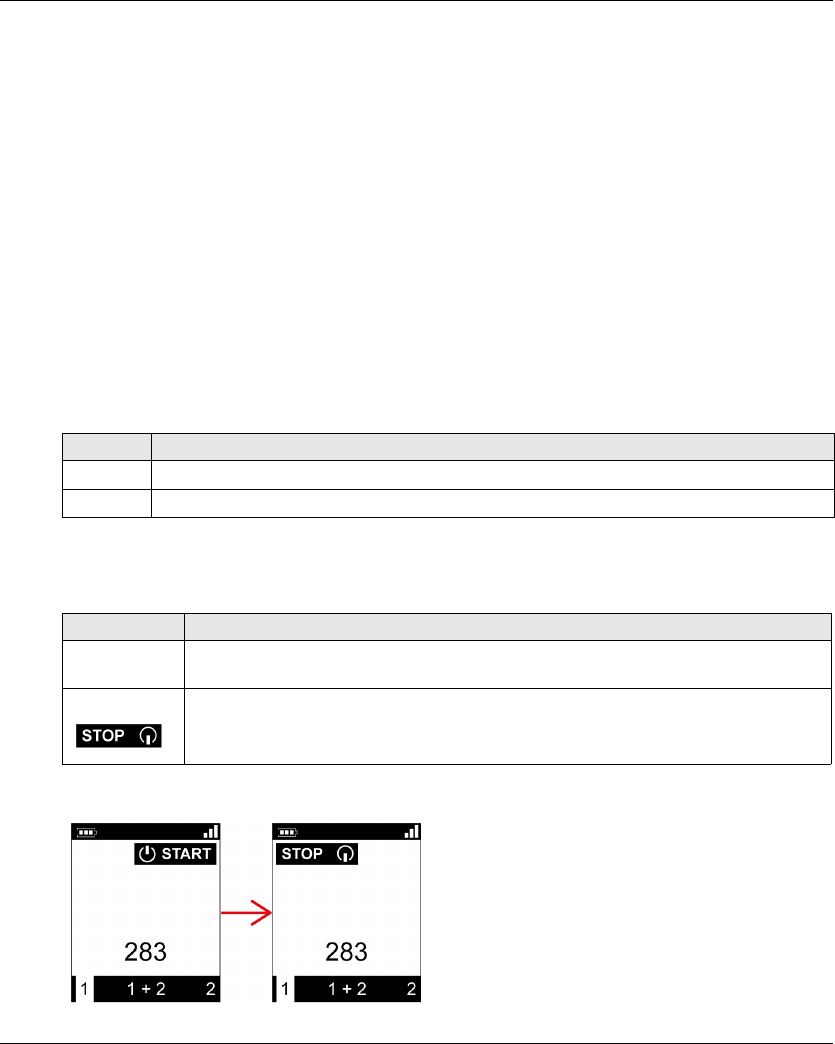
Using The Wireless Remote Control System
EIO0000001505 04/2014 123
STOP
Overview
In STOP mode, the motion/auxiliary relays are disabled and the safety relays are OFF.
Triggering Procedure
The STOP mode is reached in the following cases:
The OFF/STOP button is pressed (the Wireless Remote Control System was previously in
START mode).
No button pressed for more than the configured time-out (Standby time-out) configured in
eXLhoist Configuration Software (see page 191).
Wireless connection lost (out of range for example).
Remote Device accelerometer triggering due to:
A shock on the Remote Device
The Remote Device fall
Triggering procedure when the Wireless Remote Control System is in START mode:
Wireless Remote Control System In STOP Mode
Remote Device:
ZART•D display from START mode to STOP mode:
Step Action
1 Check that the Wireless Remote Control System is in START mode.
2 Press the OFF/STOP button.
Reference Description
ZART8L The START LED is OFF.
The E-STOP LED is ON.
ZART•D The STOP mode symbol is displayed.
The E-STOP LED is ON.

Using The Wireless Remote Control System
124 EIO0000001505 04/2014
The Base Station execute the following steps:
1 The motion/auxiliary relays are OFF.
2 If configured, the UOC relays are OFF after a pre-configured time delay.
3 The safety relays are OFF.
Base Station:
Release
From this mode, you can:
Charge the Remote Device battery (see page 143).
Power OFF the Remote Device (see page 128).
Go to START mode (seepage125).
Specifics Information
You can configure the Time-Out Auto-Standby duration in the eXLhoist Configuration Software
(seepage191).
Element Description
Relays The safety relays are OFF.
The motion/auxiliary relays are OFF.
The “Radio link” relay is ON.
The “Safety relay image” relay is ON.
LEDs The STATUS LED is blinking.
The POWER LED is ON.
The COM LED is blinking.
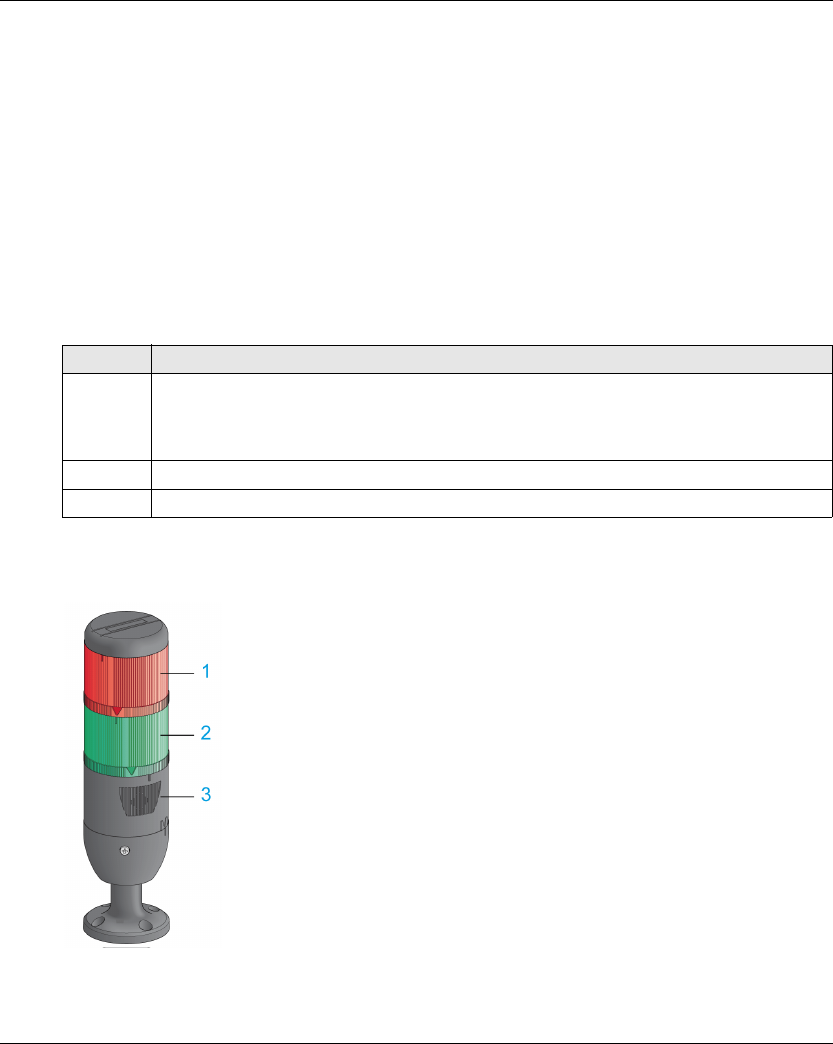
Using The Wireless Remote Control System
EIO0000001505 04/2014 125
START
Overview
The START mode is the only mode in which:
You can command the motions (see page 131).
You can command the auxiliary function (see page 133).
You can command the horn (see page 136).
The safety relays are switched ON.
Triggering Procedure
Required conditions: The Wireless Remote Control System must be in STOP mode.
Triggering procedure:
START Details
It is recommended to use a Schneider Electric beacon:
1 Light wired to the “Radio link” relay
2 Light wired to the “Safety relay image” relay
3 Buzzer wired to the “Horn” relay (an additional flash light can be wired to this relay)
Step Action
1 If a START code sequence is configured:
Type the START code sequence with the motion buttons 1, 2, 3, 4, 5, 6.
The default START code sequence is 5, 6, 5, 6.
Press the button 7 (trigger) to validate.
2 Press only the ON/START/Horn button more or equal than 1 s.
3 Wait during the START warning time (ZART•D vibrations, “Horn” relay ON).
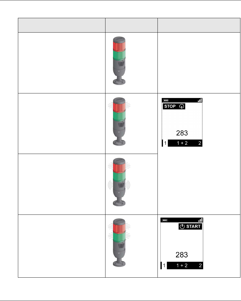
Using The Wireless Remote Control System
126 EIO0000001505 04/2014
Beacon description in the operating modes: (example with ZART•D)
Step Hoisting system
signaling
ZART•D
Before Power ON -
STOP mode
The motions are not enabled yet.
Between STOP mode and START mode:
The ZART•D vibrate facility is
activated.
The Horn sounds for the configured
time.
The motions are not enabled yet.
START mode
The motions are enabled.
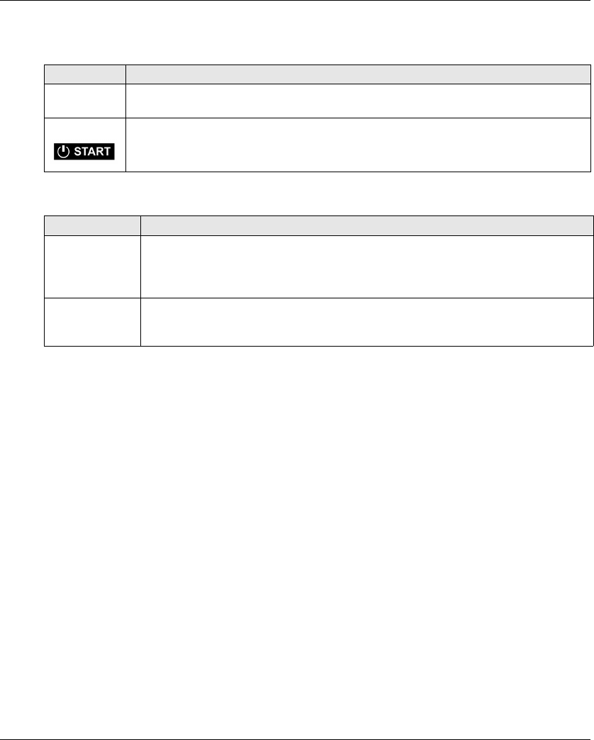
Using The Wireless Remote Control System
EIO0000001505 04/2014 127
Wireless Remote Control System In START Mode
Remote Device:
Base Station:
Release
To leave the START mode:
You can go to STOP mode (seepage123).
You can go to E-STOP mode (see page 121).
The Wireless Remote Control System goes automatically to STOP mode when no button
pressed for more than the configured time-out (standby time-out).
Specifics Information
You can configure the optional start sequence and the Horn duration during start in the eXLhoist
Configuration Software (see page 191).
Reference Description
ZART8L The START LED is ON.
The E-STOP LED is ON.
ZART•D The START mode symbol is displayed.
The E-STOP LED is ON.
Element Description
Relays The safety relays are ON.
The motion/auxiliary relays are enabled.
The “Radio link” relay is ON.
The “Safety relay image” relay is ON.
LEDs The STATUS LED is blinking.
The POWER LED is ON.
The COM LED is blinking.
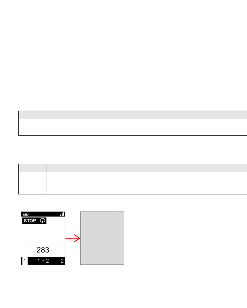
Using The Wireless Remote Control System
128 EIO0000001505 04/2014
Power OFF
Overview
This function switches OFF the Remote Device.
Triggering Procedure
Required conditions: The Wireless Remote Control System must be in STOP mode.
The "Power OFF function" is triggered in the following cases:
The OFF/STOP button is pressed.
No button pressed for more than the configured time-out: Auto Standby + Auto-OFF duration
time.
The Remote Device battery level is low.
Triggering procedure when the Wireless Remote Control System is in STOP mode:
Wireless Remote Control System In Power OFF Mode
Remote Device:
ZART•D display from STOP mode to Power OFF:
Step Action
1 Check that the Wireless Remote Control System is in STOP mode
2 Press only the OFF/STOP button more or equal than 2 s
Reference Description
ZART8L All the LEDs are OFF.
ZART•D The display is inactive.
The E-STOP LED is OFF.

Using The Wireless Remote Control System
EIO0000001505 04/2014 129
Base Station:
Release
From this mode, you can:
Power ON the Remote Device (seepage120).
Charge the Remote Device battery (see page 143).
Specifics Information
You can configure the Power-saving time out in the eXLhoist Configuration Software
(seepage191).
Element Description
Relays The safety relays are OFF.
The motion/auxiliary relays are OFF.
The “Radio link” relay is OFF.
The “Safety relay image” relay is OFF.
LEDs The STATUS LED is OFF.
The POWER LED is ON.
The COM LED is OFF.


Using The Wireless Remote Control System
EIO0000001505 04/2014 131
Standard Motion
Overview
In START mode, the motion buttons activate the associated motion relays that command the
hoisting system movements.
Triggering Procedure
Required conditions: The Wireless Remote Control System must be in START mode
(seepage125).
Triggering procedure:
Result: The associated relays are switched ON as long as the motion button is pressed.
The Remote Device has no specific result.
Release
Release procedure:
Result: The associated relays are switched OFF.
Restrictions for Motion/Auxiliary Use
Step Action
1 Check that the Wireless Remote Control System is in START mode.
2 Press a motion button 1, 1H, 2, 2H, 3, 3H, 4, 4H, 5, 5+7, 6, 6+7 (see page 24).
Step Action
1 Release the motion button.
Type Description
Number of
simultaneous
motions
Only up to 6 motion/auxiliary relays can be activated at the same time (excluding the
UOC relays).
If more than 6 motion/auxiliary relays are requested (excluding the UOC relays), then the
last motion relay request is not take into account.
Interlocking If 2 buttons dedicated to same motion axis are pressed in opposite sense (interlocking),
then the motion is stopped in these both directions.
Buttons 5 and 6 The button 7 must be released to activate the button 5 or 6.

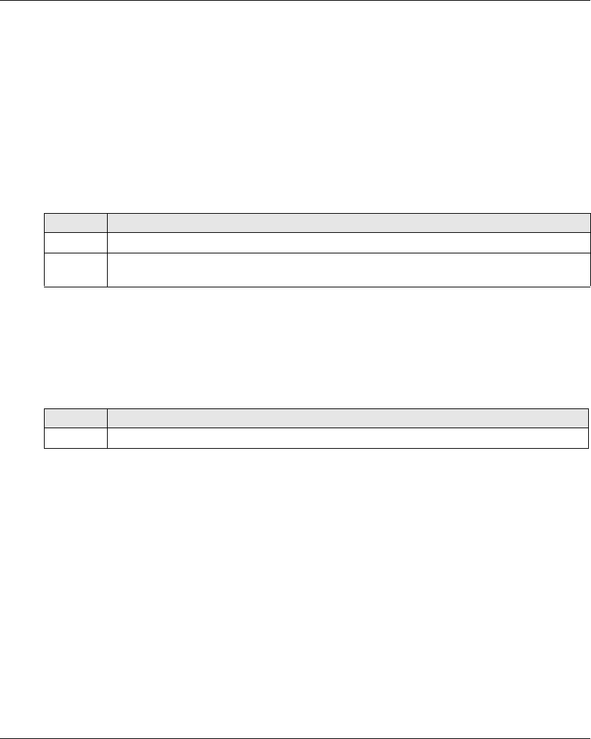
Using The Wireless Remote Control System
EIO0000001505 04/2014 133
Auxiliary Function
Overview
In START mode, the auxiliary buttons activate the associated relays to command auxiliary action
(for example to command open and close grab).
Triggering Procedure
Required conditions: The Wireless Remote Control System must be in START mode
(seepage125).
Triggering procedure:
Result: The associated relays are switched ON as long as the auxiliary button is pressed.
The Remote Device has no specific result.
Release
Release procedure:
Result: The associated relays are switched OFF.
Specifics Information
In the eXLhoist Configuration Software, you can configure:
Motion/auxiliary buttons associated to relays (see page 194).
Motion/auxiliary buttons interlocking (see page 198).
Step Action
1 Check that the Wireless Remote Control System is in START mode.
2 Press an auxiliary button (10, 10+7, 11, 11+7, 12, 12+7, 13, 13+7, 14, 14+7, 15, 15+7)
(see page 24).
Step Action
1 Release the auxiliary button.
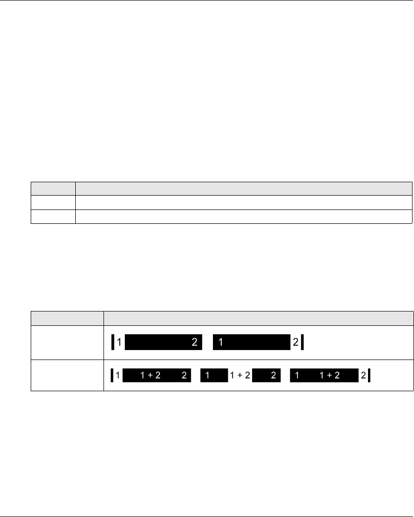
Using The Wireless Remote Control System
134 EIO0000001505 04/2014
Selector
Description
There are 3 different configurations to use the selector auxiliary button:
Bridge selector (3 positions) in TANDEM configuration: to manage 2 bridges by using 2 Base
stations.
Trolley selector (2 or 3 positions): to manage 2 trolleys with one Base Station.
Hook selector (2 positions): to manage 2 hooks with one Base Station.
Triggering Procedure
Required conditions: The Wireless Remote Control System must be in STOP mode
(seepage123).
Triggering procedure:
Wireless Remote Control System Result
Remote Device:
For the ZART8L: the Selector LEDs are activated depending on the selection done.
For the ZART•D display: the Selector symbol indicates which bridge(s)/trolley(s)/hook(s) is(are)
selected:
Base Station relays:
The associated relay(s) is(are) switched ON.
In TANDEM configuration, when the Base stations 1 and 2 are selected, the motions asked with
the Remote Device are realized simultaneously by the 2 Base stations.
Step Action
1 Check that the Wireless Remote Control System is in STOP mode.
2 Press the Selector button more or equal than 1 s to loop between the several positions.
Nb of position Description
2
3
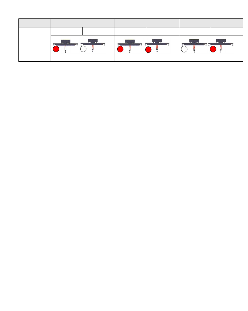
Using The Wireless Remote Control System
EIO0000001505 04/2014 135
In TANDEM configuration, the “Radio link” relay of the selected Base Station switches ON:
Specifics Information
At the first Power ON, the Selector position is 1. For further Power ON, the Selector position is the
last known Selector position.
You can configure the Selector in the eXLhoist Configuration Software (see page 194).
Relay Selector position 1 Selector position 1+2 Selector position 2
RADIO link Bridge 1 Bridge 2 Bridge 1 Bridge 2 Bridge 1 Bridge 2
Using The Wireless Remote Control System
136 EIO0000001505 04/2014
Horn
Overview
From STOP mode to START mode, the “Horn” relay is switched ON for a predefined duration time.
In START mode, as long as you press the ON/START/Horn button, the “Horn” relay is switched
ON.
Triggering Procedure
Triggering procedure:
Result: The “Horn” relay is switched ON as long as the ON/START/Horn button is pressed.
The Remote Device has no specific result.
Release
Release procedure:
Result: The “Horn” relay is switched OFF.
Specifics Information
The Horn duration during start can be configured in the eXLhoist Configuration Software
(seepage193).
Step Action
1 Check that the Wireless Remote Control System is in START mode.
2 Press the ON/START/Horn button.
Step Action
1 Release the ON/START/Horn button.

Using The Wireless Remote Control System
EIO0000001505 04/2014 137
Discovering
Section 5.3
Discovering
Discovering
Overview
The discovering function is developed to be as automatic as possible.
This function manages 2 different tasks:
The pairing of the system: association between a Remote Device and a Base Station
The Configuration File Upload/Download: this file contains the Wireless Remote Control System
configuration information.
This function is launched at each Remote Device Power ON. In normal use, this function is
automatic. You have to realize intermediate operations during:
A device replacement (seepage203)
The first commissioning (see page 114)
NOTE: This function is only applicable to ZAR•D Remote Device.
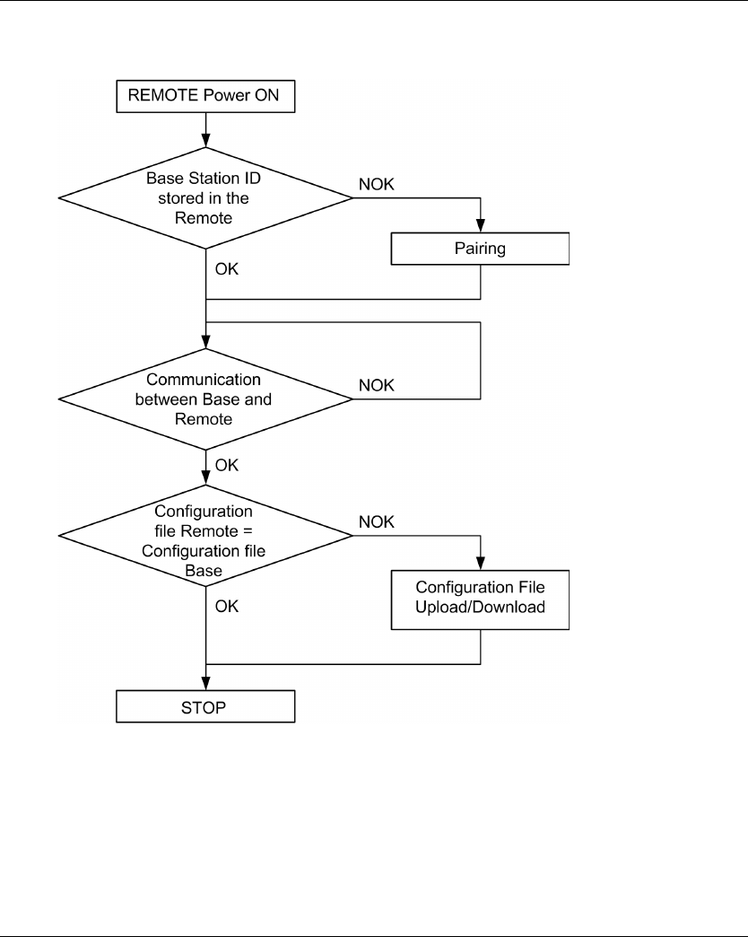
Using The Wireless Remote Control System
138 EIO0000001505 04/2014
Discovering Diagram
The following diagram presents the detailed Discovering function:
Pairing
The pairing is the action to associate a Base Station with a Remote Device.
Each Base Station have a unique ID.
The pairing test is launched at each Remote Device power ON.
As long as the pairing test is OK, the validation procedure is not requested to the operator.

Using The Wireless Remote Control System
EIO0000001505 04/2014 139
Configuration File
The Configuration File is stored in the Remote Device and in the Base Station.
The Configuration File can be created or modified in the eXLhoist Configuration Software
(seepage161).
It contains:
The Remote Device reference
The Base Station ID
The Base Station reference
The button/relay associations
The UOC relay assignment and time delay defined
The detected applicative alarm configuration
The safeguarding configuration
The standby time-out and power-saving time-out
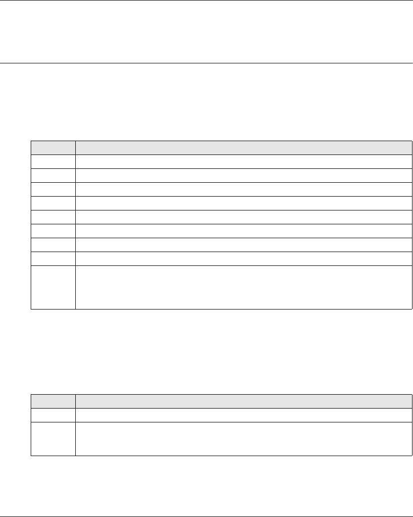
Using The Wireless Remote Control System
140 EIO0000001505 04/2014
How to Modify the Configuration
Section 5.4
How to Modify the Configuration
How to Modify a Configuration
Configuration Modification
The following procedure describes how to modify the system configuration:
Result: The Remote Device goes to STOP mode (see page 123).
It is recommended to redo an Acceptance Test (see page 75).
Configuration File load With a ZART8L
After the modification of the configuration with the eXLhoist Configuration Software:
Result: The Remote Device goes to STOP mode (see page 123).
It is recommended to redo an Acceptance Test (see page 75).
Step Action
1 Connect the Remote Device to a PC (see page 165).
2 Start the eXLhoist Configuration Software (see page 178).
3 Create a project (see page 179).
4 Modify the configuration of the project (see page 188)
5 Select Communication → Store to Device.
6 Wait for the end of the Configuration File load in the Remote Device.
7 Disconnect the Remote Device to the PC.
8 Power ON the Base Station.
9 The Configuration File must be loaded from the Remote Device to the Base Station.
Refer to:
Configuration File load With a ZART8L (see page 140).
Configuration File load With a ZART•D (see page 141).
Step Action
1 Power ON the Remote Device.
2 The Configuration File is automatically loaded from the Remote Device to the Base Station.
During the load, the START LED and “2” LED are flashing (see page 157) .
Wait for the end of the Configuration File load.
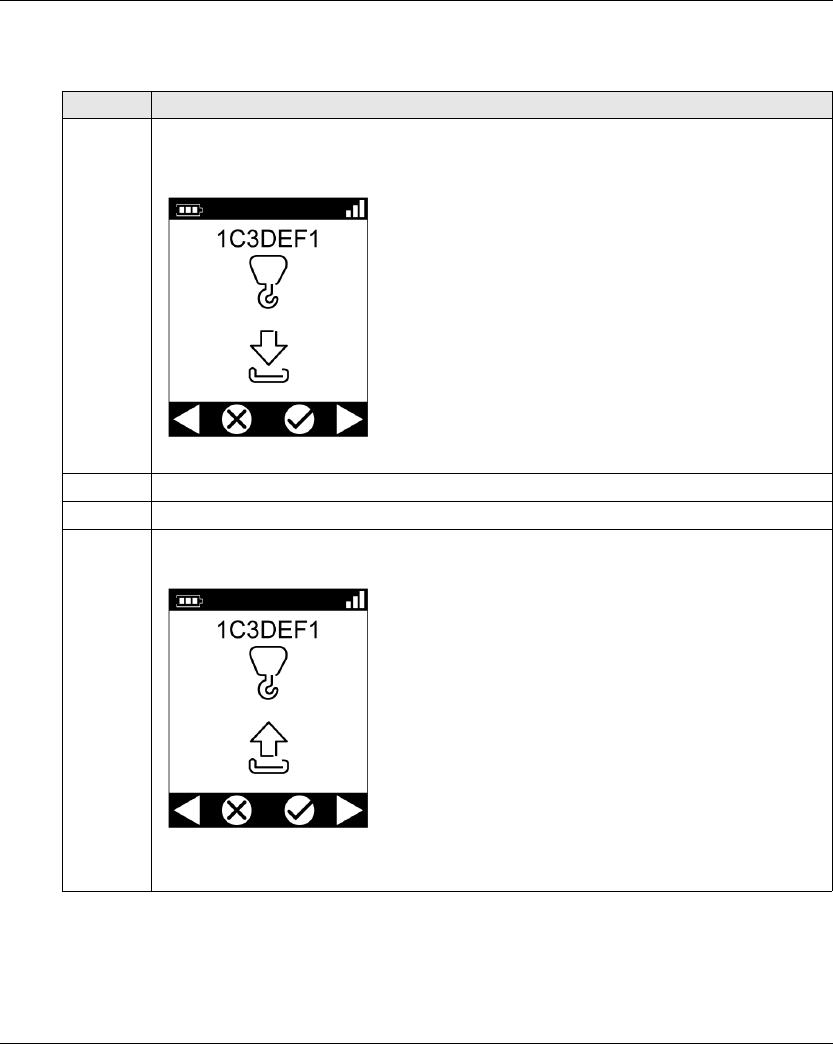
Using The Wireless Remote Control System
EIO0000001505 04/2014 141
Configuration File load With a ZART•D
After the modification of the configuration with the eXLhoist Configuration Software:
Step Action
1 Power ON the Remote Device.
Result: The Remote Device propose to load the Configuration File from the Base Station to the
Remote Device.
2 Select the cancel cell (X) with buttons 1 and 2.
3 Press the button 7 (trigger) to validate.
4 The Remote Device propose to load the Configuration File from the Remote Device to the Base
Station.
Select the validation cell (check symbol) with buttons 1 and 2.

Using The Wireless Remote Control System
142 EIO0000001505 04/2014
Result: The Remote Device goes to STOP mode (see page 123).
It is recommended to redo an Acceptance Test (see page 75).
5 If the Configuration File has a transfer password, a padlock is displayed:
Enter the Configuration File transfer code with the buttons 1 to 6.
The default transfer password is 5, 6, 5, 6.
6 Press the button 7 (trigger) to validate.
Result: The Remote Device loads the Configuration File from the Remote Device to the Base
Station.
7 Wait for the end of the Configuration File load.
Step Action
Using The Wireless Remote Control System
EIO0000001505 04/2014 143
Remote Device Charge
Section 5.5
Remote Device Charge
Remote Device Charge
Required Conditions
The Remote Device must only be charged indoor with the ZARC01 charger.
The Remote Device must be in STOP mode or Power OFF.
The Remote Device temperature range must be 10…60 °C (50…140 °F) in case of battery
charge.
NOTE: At the first commissioning, you must charge the Remote Device for 30 minutes.
NOTE: The Remote Device charge time is 15 minutes long at the maximum if the temperature
range is 10…35 °C (50…95 °F), and is longer if the temperature is higher than 35 °C (95 °F).
WARNING
BATTERY LIFESPAN, RISK OF EXPLOSION AND FIRE
Do not dispose of electric tools together with household waste material.
In observance of european directive 2002/96/EC on wasted electrical and electronic equipment
and its implementation in accordance with national law, electric tools that have reached the end
of their life must be collected separately and returned to an environmentally compatible recycling
facility.
Failure to follow these instructions can result in death, serious injury, or equipment
damage.
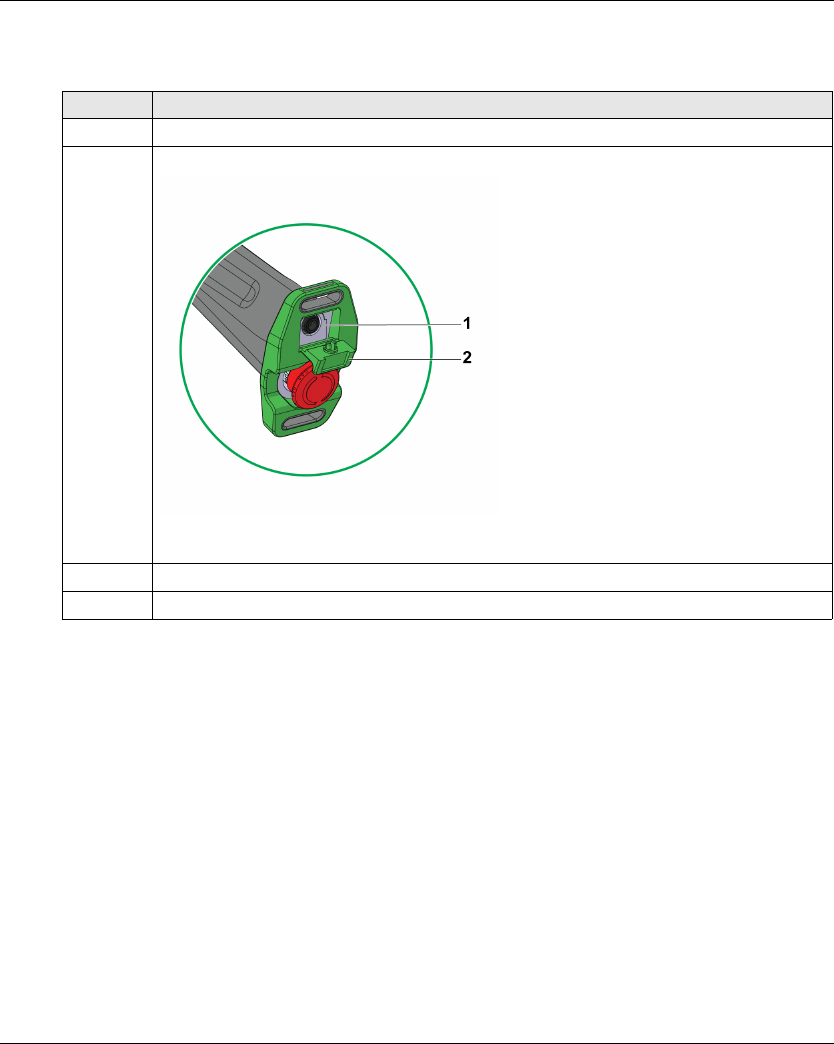
Using The Wireless Remote Control System
144 EIO0000001505 04/2014
Procedure
Step Action
1 Power OFF the Remote Device.
2 On the bottom of the Remote Device, remove the protective cap.
1 Remote Device battery charge connector
2 Protective cap
3 Connect the charger to the Remote Device battery charge connector.
4 Plug the charger to the dedicated power source.
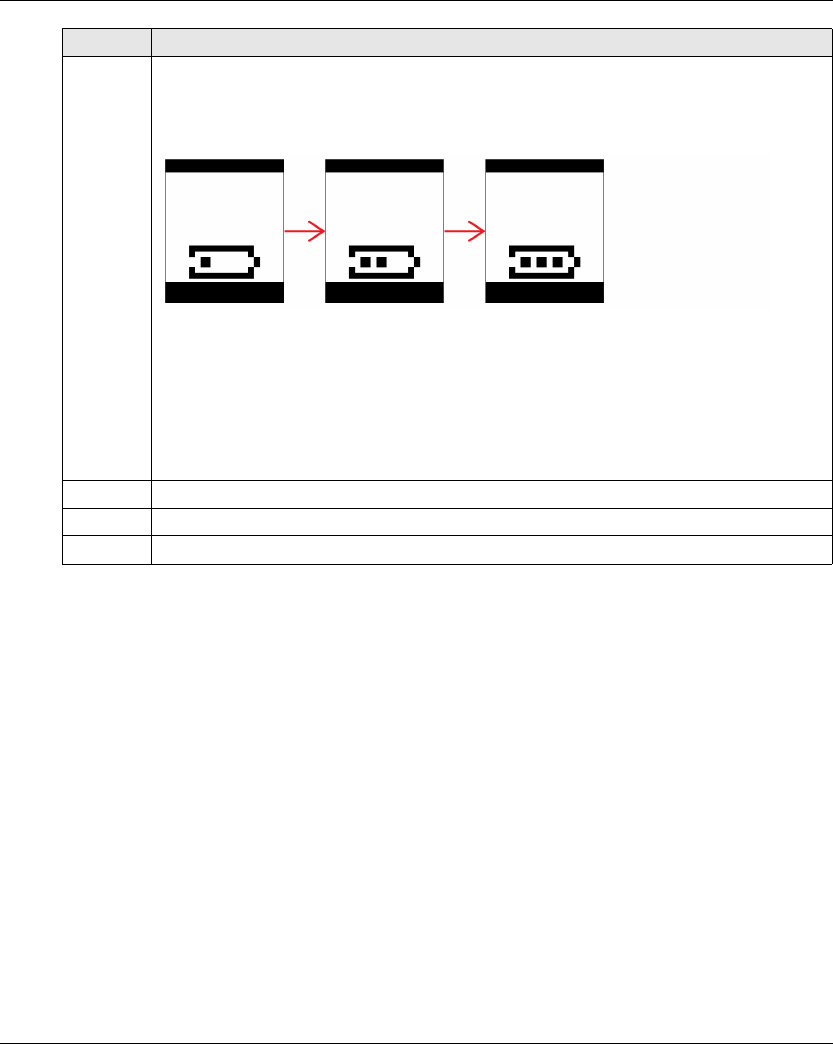
Using The Wireless Remote Control System
EIO0000001505 04/2014 145
NOTE: If the system is in START mode, it goes automatically in STOP mode at the connection of
the charger.
5 Wait for around 15 minutes.
During the charge:
ZART8L: the battery LED is flashing.
ZART•D: the blinking battery symbol indicates the battery level:
The battery is fully charged when:
ZART8L: the battery LED is permanently ON.
ZART•D: the battery symbol is permanently displayed.
For more details, refer to Diagnostic (see page 153).
NOTE: The time duration for charge or the Remote Device depends on the ambient
temperature.
6 Unplug the charger to the dedicated power source.
7 Unconnect the charger to the Remote Device battery recharge connector.
8 On the bottom of the Remote Device, place back the protective cap.
Step Action

Using The Wireless Remote Control System
146 EIO0000001505 04/2014

Diagnostic
148 EIO0000001505 04/2014
Base Stat ion Diagnostic
Section 6.1
Base Station Diagnostic
Diagnostic
Description
The Base Station have 3 LED indicators:
LED Color State Description
STATUS Green Blinking The Wireless Remote Control System is working properly.
OFF Base Station Power OFF or internal fault detected.
COM Yellow OFF No communication between the Base Station and the Remote Device.
Blinking The communication is established between the Base Station and the
Remote Device.
POWER White OFF Base Station powered OFF.
ON Base Station powered ON.

Diagnostic
EIO0000001505 04/2014 149
ZART•D Diagnostic
Section 6.2
ZART•D Diagnostic
What Is in This Section?
This section contains the following topics:
Topic Page
Diagnostic Mode 150
Radio Communication Indicator 152
Battery Level of the Remote Device 153
E-STOP LED 154
Applicative Alarms Signals 155
Detected Failure Displays 156
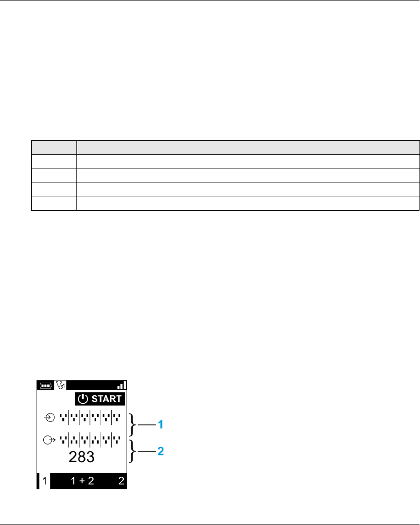
Diagnostic
150 EIO0000001505 04/2014
Diagnostic Mode
Overview
To test the Wireless Remote Control System configuration, the ZART•D has a specific diagnostic
mode display.
Procedure to Activate the Diagnostic Mode
The diagnostic mode on the ZART•D indicates the inputs and relays states of the Base Station.
Diagnostic Display Description
In STOP mode, use the buttons 5 and 6 to alternate between the 3 screens:
Base Station information:
ID
Hardware version
Firmware version
Remote Device information:
ID
Hardware version
Firmware version
Remote Device battery information (only for Schneider-Electric use).
In START mode, the Remote Device displays dynamically the I/O status:
1 IN1...IN18 states: up for input = 1, down for input = 0
2 Relays 1...18 states: up for output = 1, down for output = 0
Step Action
1 Go to STOP mode (see page 123).
2 Simultaneously press the buttons 1 and 2, and release immediately.
3 Less than 5 seconds later, simultaneously press the buttons 3 and 4.
4 Release the buttons 3 and 4.

Diagnostic
EIO0000001505 04/2014 151
Procedure to Leave the Diagnostic Mode
Step Action
1 Power OFF the Remote Device
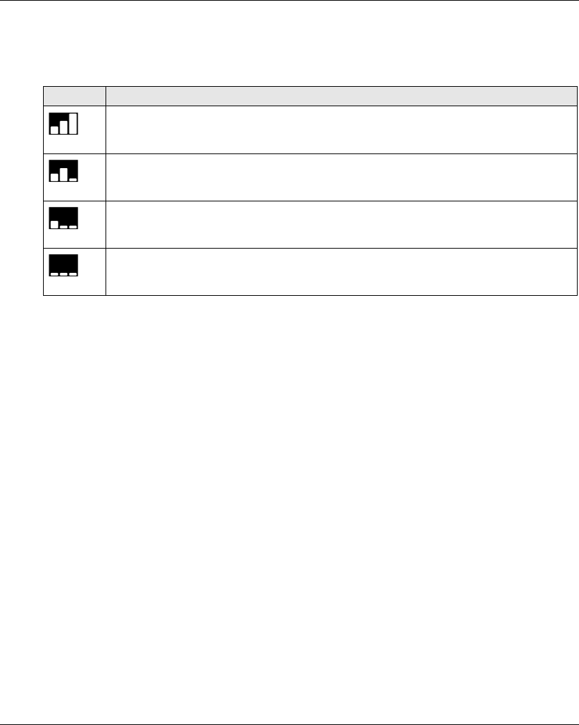
Diagnostic
152 EIO0000001505 04/2014
Radio Communication Indicator
ZART•D
Display ZART•D radio communication level with the Base Station
High
Medium
Low
No radio communication
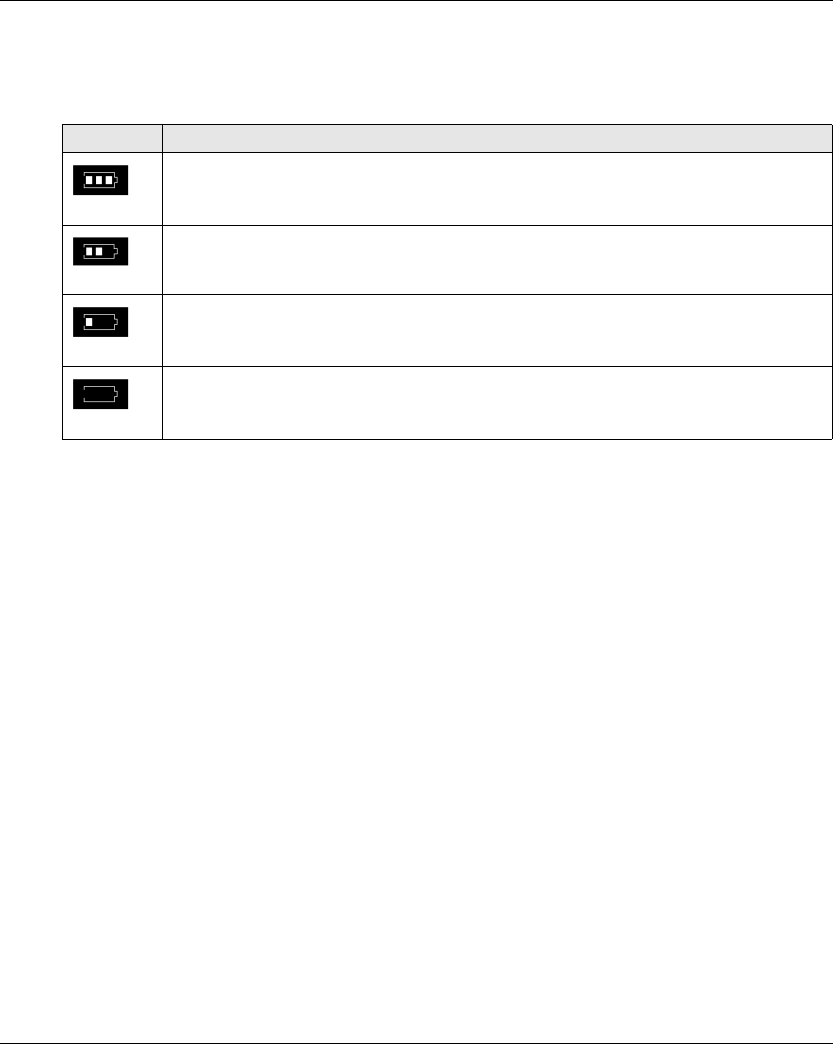
Diagnostic
EIO0000001505 04/2014 153
Battery Level of the Remote Device
ZART•D
Display Description
Battery charge level is high
Battery charge level is medium
Battery charge level is low
This display occurs at least 10 minutes before the Remote Device cannot properly work.
In addition, the Remote Device vibrate facility is activated for 1 second.

Diagnostic
154 EIO0000001505 04/2014
E-STOP LED
Description
E-STOP LED Description
Permanently ON E-STOP is operational and not triggered.
Blinking at a frequency of 1 Hz. E-STOP is operational and triggered.
Permanently OFF E-STOP is not operational.
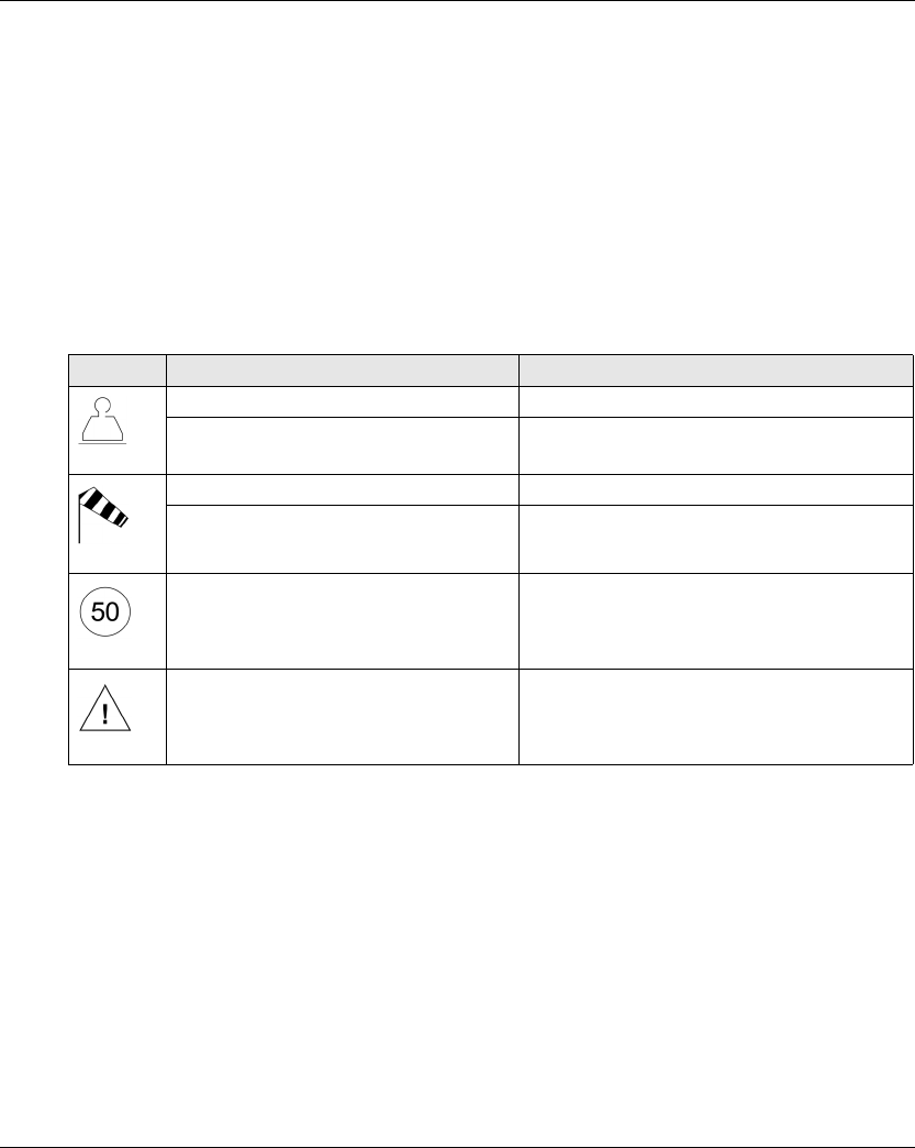
Diagnostic
EIO0000001505 04/2014 155
Applicative Alarms Signals
Overview
Some devices can be connected to the ZARB18• Base Station to provide detected applicative
alarms signals that can be displayed in the ZART•D.
ZART•D
When applicative alarms signals come from ZARB18• Base Station, the ZART•D Remote Device
involves a symbol display and 3 seconds of vibration every 10 minutes as long as the alarm signal
is active.
The Remote Device displays the following symbols:
NOTE: The applicative alarms are only information, the Wireless Remote Control System does not
change its functional mode.
Display Status Description
Permanently ON Overload pre-alarm
Blinking at a frequency of 1 Hz Overload alarm
Permanently ON Over wind pre-alarm
Blinking at a frequency of 1 Hz Over wind alarm
Blinking at a frequency of 1 Hz Over speed alarm
Blinking at a frequency of 1 Hz Generic alarm
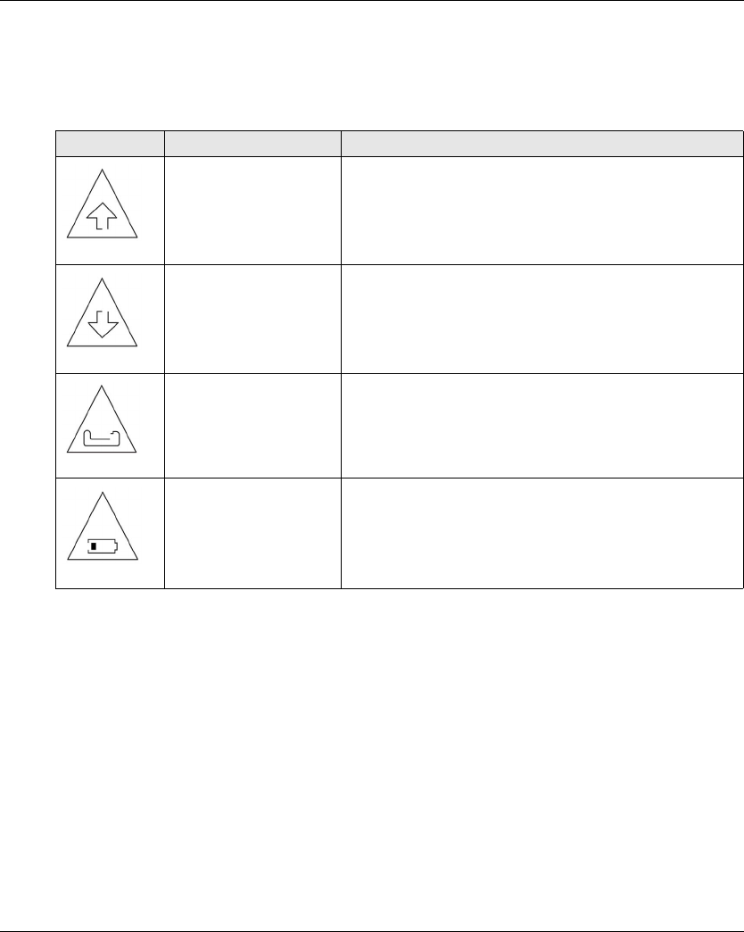
Diagnostic
156 EIO0000001505 04/2014
Detected Failure Displays
ZART•D
The ZART•D Remote Device can display the following symbols:
Display Status Description
Blinking Configuration File download failure detected
Blinking Configuration File upload failure detected
Blinking Remote Device failure detected
Blinking Remote Device battery charge failure detected
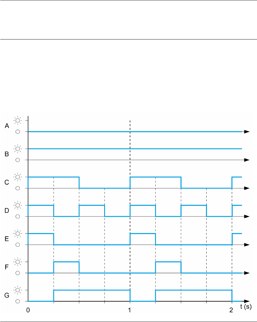

Diagnostic
158 EIO0000001505 04/2014
Start LED
Battery LED
Charger ZARC01 not connected
Label Status
AOFF
BON
C Normal blink
DFast blink
E Flash step 1
F Flash step 2
G Reverse flash step 1
Label Status Description
B ON The system is in START mode with radio operational
C Normal blink Radio not established or START mode not yet confirmed
F Reverse flash step 1 A password has not yet been provided & validated (either for before
START, or after unlocking the E-Stop before START)
D Fast blink Wrong Configuration File
E Flash step 1 The Remote Device is connected to a PC.
A OFF To represent other states than the previous ones
Label Status Description
B ON Battery charge level is high
Battery charge level is medium
C Normal blink Battery charge level is low
D Fast blink Battery charge level is very low
The battery capacity just allows 10 minutes of normal operation.
A OFF The battery is fully discharged or the Remote Device is Power OFF.

Diagnostic
EIO0000001505 04/2014 159
Charger ZARC01 connected
Once the Remote Device is connected to the battery charger, the battery LED flashes 3 times (E
label = FLASH_STEP_1). After the 3 flash, the battery LED status changes to the following ones:
Selector LEDs
The “1” LED:
The “2” LED:
Set of LEDs
Power ON - Check LEDs:
At Remote Device Power ON, the 4 LEDs (START, Battery, 1, and 2) flash one time (status E =
Flash step 1).
Remote failure detected:
If a remote internal failure is detected, the 4 LEDs go in the following status:
The START LED is in status E = Flash step 1
The BATTERY LED is in status E = Flash step 1
The “1” LED is in status E = Flash step 1
The “2” LED is in status E = Flash step 1
Label Status Description
B ON Battery charge level is full (No need to charge or end of charge)
E Flash step 1 Battery charge in progress
C Normal blink Impossible to charge (charger failure detected) or temperature out of
the allowed boundaries
A OFF Impossible to charge (battery too low to be charged)
Label Status Description
B ON The “1” or the “1+2” selector position is selected and confirmed
C Normal blink The “1” or the “1+2” selector position is required but not yet confirmed
A OFF The selector position “1” is NOT selected
Label Status Description
B ON The “1+2” or the “2” selector position is selected and confirmed
C Normal blink The “1+2” or the “2” selector position is required but not yet confirmed
A OFF The selector position “2” is NOT selected

Diagnostic
160 EIO0000001505 04/2014
Configuration file download:
During the transfer of a Configuration File (from the Remote Device to the Base Station):
The START LED is in status E = Flash step 1
The “2” LED is in status F = Flash step 2
Remote device reset:
When you press the reset button : until the “1” and “2” LED comes in the following status:
The “1” LED is in status E = Flash step 1
The “2” LED is in status A = OFF
E-STOP LED
Label Status Description
B ON E-STOP is operational and not triggered.
C Normal blink E-STOP is operational and triggered.
A OFF E-STOP is not operational.

EIO0000001505 04/2014 161
Harmony eXLhoist
eXLhoist Configurat ion Software
EIO0000001505 04/2014
eXLhoist Configurat ion Software
Chapter 7
eXLhoist Configuration Software
What Is in This Chapter?
This chapter contains the following sections:
Section Topic Page
7.1 Introduction to eXLhoist Configuration Software 162
7.2 User Interface 168
7.3 Project Management 175
7.4 Configuration 188

eXLhoist Configuration Software
162 EIO0000001505 04/2014
Introduction to eXLhoist Configuration Software
Section 7.1
Introduction to eXLhoist Configuration Software
What Is in This Section?
This section contains the following topics:
Topic Page
What is eXLhoist Configuration Software? 163
Connect a Remote Device to the PC 165
Installation 167

eXLhoist Configuration Software
EIO0000001505 04/2014 163
What is eXLhoist Configuration Software?
Introduction
eXLhoist Configuration Software is a graphic user interface allowing you to manage the
configuration of the Wireless Remote Control System.
Software Features
Main software features of eXLhoist Configuration Software:
Standard Windows® interface
Application browser and multiple window views
Programming and configuration support
Communication with controller
Standard Windows® Interface
Key standard Windows® features:
Easy use of keyboard or mouse
Dockable windows
Standard menu organization
Tooltips, status bar, and shortcut menus
Online help including context-sensitive help
Controller Communication and Control
Main eXLhoist Configuration Software features for remote support:
Connecting and disconnecting a remote
Downloading and uploading remote configuration files
Additional Information
Refer to the following for additional information:
For information on standard Windows® interface features, refer to Microsoft Windows®
documentation and help files.
For context-sensitive help, first click in the main window and then press F1 or click the help
buttons in dialog boxes.

eXLhoist Configuration Software
164 EIO0000001505 04/2014
Conventions
The following typographic conventions are used in this operation guide.
Format Represents
Bold For user input, enter words or phrases shown in bold as they appear. Menu names
and options, commands and toolbar names, and dialog box names and options are
also shown in bold type.
UPPER CASE Keyboard names, combinations, and sequences are shown in all uppercase
letters. For example, the keyboard shortcut for creating a new application is
CTRL+N. To perform this shortcut, press and hold the CTRL key and then press
the N key.
File → Open The arrow indicates a menu selection. In this instance, go to the File menu to select
the Open command.
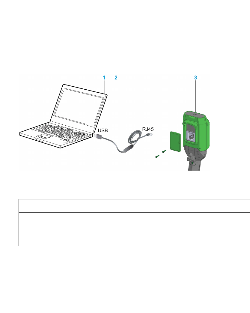
eXLhoist Configuration Software
EIO0000001505 04/2014 165
Connect a Remote Device to the PC
Introduction
The connection is made using the RJ45 to USB converter cable.
It is recommended to Power OFF the Remote Device before connecting it to the PC
Description
The figure illustrates the connection to a personal computer:
1 Personal computer
2 USB to RJ45 converter cable: TCSMCNAM3M002P
3 Remote Device
The PC does not supply the Remote Device. As long as the Remote Device is connected to the
PC, it is recommended to charge the remote (see page 143).
NOTICE
INOPERABLE EQUIPMENT
Always connect the communication cable to the PC before connecting it to the device.
Only use the Schneider Electric cable TCSMCNAM3M002P.
Failure to follow these instructions can result in equipment damage.
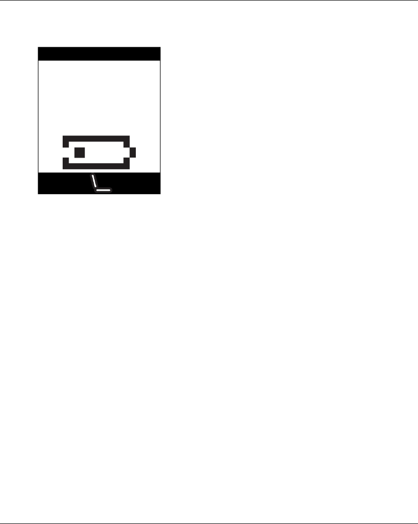
eXLhoist Configuration Software
166 EIO0000001505 04/2014
As long as the Remote Device is connected to the PC:
ZART•D: a dedicated screen is displayed
ZAR8L: The Start LED is flashing.

eXLhoist Configuration Software
EIO0000001505 04/2014 167
Installation
Introduction
The software can be downloaded from www.schneider-electric.com.
It must be installed via an administrator account.
Prerequisites
eXLhoist Configuration Software requires the following minimal configuration:
Dual core processor
RAM: 2 GB
Required disk space: 2 GB
Windows® XP SP3 32 bits / 7 Pro 32 bits
Installation Process
To install eXLhoist Configuration Software, follow the steps below:
Step Action
1 Double-click the program file (setup.exe).
2 If the .NET® framework 3.5 SP1 is not already installed, the installer automatically installs it.
3 Follow all the steps.

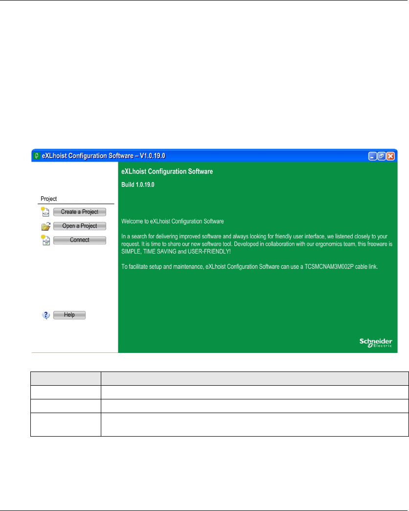
eXLhoist Configuration Software
EIO0000001505 04/2014 169
Starting Screen
Introduction
The eXLhoist Configuration Software starting window is displayed at software launching. It
provides easy access to the main functions:
Create a new project.
Open an existing project.
Connect a Remote Device.
Description
The illustration shows the eXLhoist Configuration Software starting screen:
For more details, refer to Create a project (seepage179).
Button Description
Create a Project Allows you to create a new project with default values.
Open a Project Allows you to open an existing project. Project files have the “xpf” extension.
Connect Allows you to create a project with the data stored in a Remote Device.
The data are uploaded from the Remote Device to the PC.
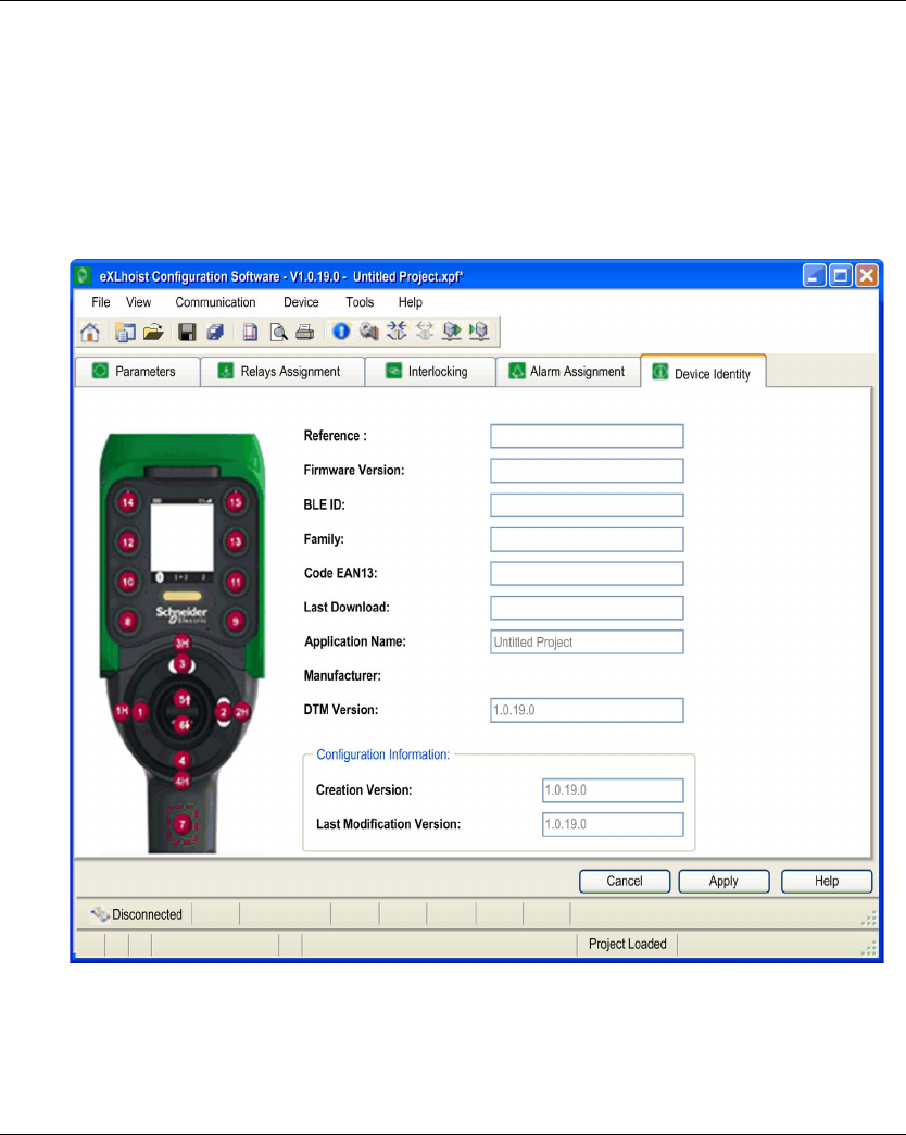
eXLhoist Configuration Software
170 EIO0000001505 04/2014
Main Window
Introduction
The eXLhoist Configuration Software main window provides access to menus and commands,
windows and toolbars, and views of an application.
Description
The illustration shows the eXLhoist Configuration Software main window:

eXLhoist Configuration Software
EIO0000001505 04/2014 171
Status Bar
Introduction
The status bar is a panel at the bottom of the main window that displays information about the
application and the connected device. The status bar can be turned on or off by selecting View →
Status Bar from the menu bar.
Description
The status bar displays:
Status messages and prompts
Project status
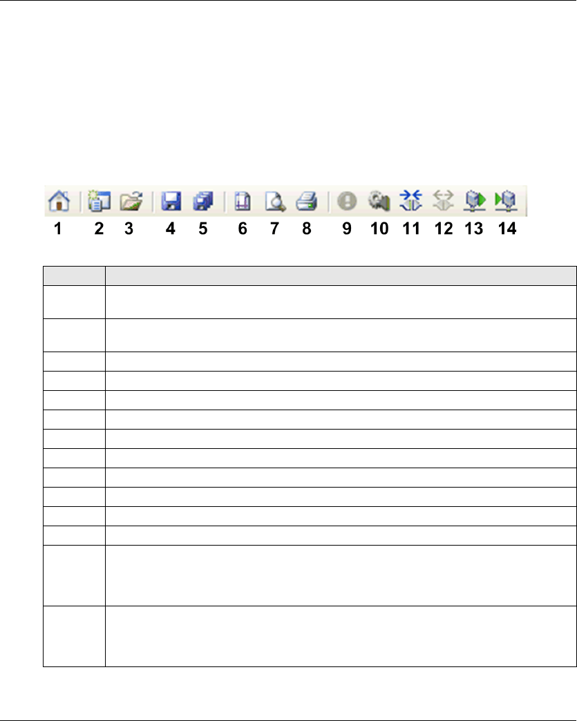
eXLhoist Configuration Software
172 EIO0000001505 04/2014
Toolbar
Introduction
The toolbar is a panel at the top of the main window which provides access to the main commands
using icons.
The toolbar can be turned on or off by selecting View → Toolbar from the menu bar.
Description
The illustration shows the eXLhoist Configuration Software toolbar:
Element Description
1Go to Start Page: Displays the start page, any opened project must be closed. If the project is
not saved, a dialog box asks to save the project.
2New Project: Creates new project, any opened project must be closed. If the project is not
saved, a dialog box asks to save the project.
3Open Project: Opens a project saved on your computer.
4Save: Saves modifications to an existing project.
5Save As: Saves an open project under a name and/or in a new location.
6Page Setup: Ables to configure the printing page setup.
7Print Preview: Displays the print preview.
8Print: Prints the project.
9Identify Device (see page 189)
10 Edit Connection (see page 182).
11 Connect to Device: Establishes the connection between the remote and the software.
12 Disconnect from Device: Disconnects the connection between the remote and the software.
13 Load From Device: Loads the parameters from the connected remote to the project file.
If no project is opened, this command loads the remote information to the project file.
If a project is opened, this command loads the remote configuration to the project. Project data
are overwritten.
14 Store to Device: Transfer configuration from project to the remote.
If no project is opened, this command downloads the existing project file information to the
remote.
If a project is opened, this command transfers the project information to the remote.
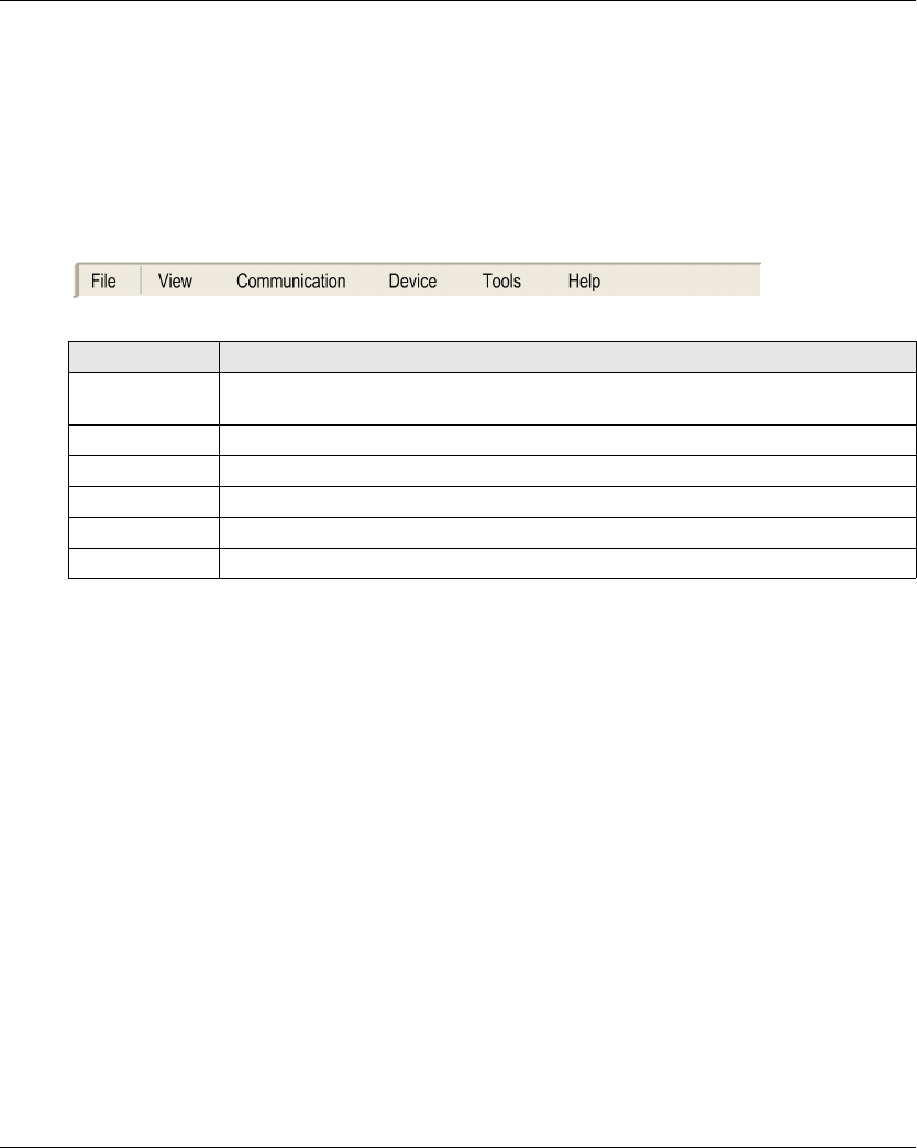
eXLhoist Configuration Software
EIO0000001505 04/2014 173
Menu Bar
Introduction
The menu bar is a panel at the top of the main window which provides access to the command
menus.
Description
The illustration shows the eXLhoist Configuration Software menu bar:
Menu Description
File Available to launch file related operations (New, Open, Export, Print, Save, Close, and
so on).
View Available to toggle the toolbar and status bar visibility.
Communication Available to manage the communication-related operation.
Device Available to manage the Transfer Configuration File Password (see page 183).
Tools Available to switch the language of the eXLhoist Configuration Software.
Help Available to manage the Help and About of the eXLhoist Configuration Software.
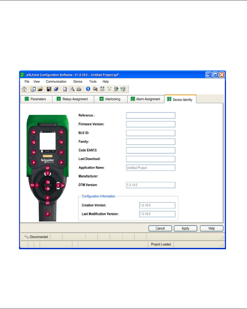
eXLhoist Configuration Software
174 EIO0000001505 04/2014
Workspace
Introduction
The eXLhoist Configuration Software workspace provides access to the connected remote
parameters.
Description
The illustration shows the eXLhoist Configuration Software workspace:
The following tabs are available from the workspace:
Parameters (see page 191)
Relays Assignment (see page 194)
Interlocking (see page 198)
Alarm Assignment (seepage199)
Device Identity (seepage189)

eXLhoist Configuration Software
EIO0000001505 04/2014 175
Project Management
Section 7.3
Project Management
What Is in This Section?
This section contains the following topics:
Topic Page
Diagram 176
Starting and Exiting eXLhoist Configuration Software 178
Creating a Project 179
Edit a Connection 182
Project Passwords Management 183
Load the Configuration into the Remote Device 185
Save a Project 186
Export to PDF 187

eXLhoist Configuration Software
176 EIO0000001505 04/2014
Diagram
Uses Cases
The main use cases of the eXLhoist Configuration Software are:
Create a project.
Open an existing project.
Open a new project using data from remote connected.
Save project.
Close project.
Generate the configuration documentation to export in “.pdf” file.
Transfer configuration from PC to Remote Device.
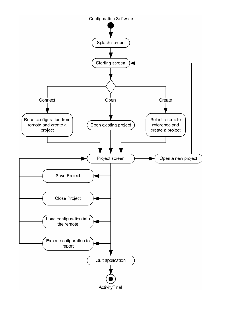
eXLhoist Configuration Software
EIO0000001505 04/2014 177
The diagram illustrates the use cases:

eXLhoist Configuration Software
178 EIO0000001505 04/2014
Starting and Exiting eXLhoist Configuration Software
Starting eXLhoist Configuration Software
The installation procedure for eXLhoist Configuration Software creates one or more of the following
options for starting the software, depending on selections made during installation.
Select one of the following options to start eXLhoist Configuration Software:
Double-click the eXLhoist Configuration Software icon on the Windows® desktop.
Select the eXLhoist Configuration Software entry from the Windows® programs menu.
Select Run from the Windows® start menu and browse for the eXLhoist Configuration Software
program.
eXLhoist Configuration Software starts and the starting screen is displayed.
Exiting eXLhoist Configuration Software
To exit eXLhoist Configuration Software:
Step Action
1 Select File → Exit from the main menu.
If there is no change, the application closes and eXLhoist Configuration Software exits to the
Windows® desktop.
If there are changes, an exit dialog box is displayed prompting you to save changes.
2 Select Yes to save changes and exit eXLhoist Configuration Software.
Select No to discard changes and exit.
Select Cancel to return to eXLhoist Configuration Software with changes intact.
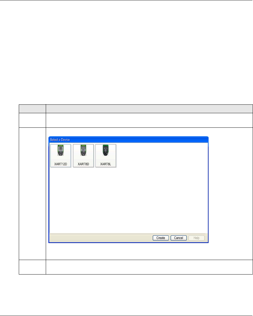
eXLhoist Configuration Software
EIO0000001505 04/2014 179
Creating a Project
Overview
As shown in the eXLhoist Configuration Software diagram, there are 3 ways to start a project:
Create a new project with default values (see page 179).
Open an existing project (seepage180).
Create a new project with the configuration stored in a connected Remote Device
(seepage180).
These 3 ways can be realized form the starting screen but also from the main menu.
Create a New Project with Default Values
Follow the procedure to create a new project with default values.
Step Action
1 From the starting screen, click Create a project button.
Note: From the main menu, select File → New.
2 A device selection window is displayed:
Select the appropriate device.
3 Click Create button.
Result: The project window is activated.
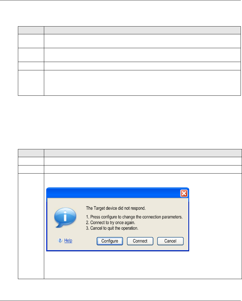
eXLhoist Configuration Software
180 EIO0000001505 04/2014
Open an Existing Project
Follow the procedure to open an existing project from your PC:
Note: If you do not enter the correct project password, the project is nevertheless opened but in
“Locked” mode. In this mode, only the Device Identity tab content is displayed.
Create a New Project with the Configuration Stored in a Remote Device
Follow the procedure to create a new project with the configuration stored in a connected Remote
Device:
Step Action
1 From the starting screen, click Open a project button.
Note: From the main menu, select File → Open.
2 A browser window is displayed.
Select the project file (“.xpf”).
3 Click Open.
4 If the project file is locked, a window is displayed.
Enter the project password (see page 184).
Click Enter.
The project window is activated.
Step Action
1 Connect a Remote Device to the PC (see page 165).
2 From the starting screen, click Connect button.
3 If the communication between the PC and the Remote Device is not established, a window is
displayed:
Click Configure to display the Edit Connection windows (see page 182).
Click Connect to retry the connection.
Click Cancel to cancel the connect procedure.

eXLhoist Configuration Software
EIO0000001505 04/2014 181
NOTE: If you do not enter the correct project password, the project is nevertheless opened in
“Locked” mode. In this mode, only the Device Identity tab content is displayed.
4 If the configuration in the Remote Device has a transfer Configuration File password, a window
is displayed.
Enter the Transfer Password (see page 183) with the keyboard of the PC.
Click Enter.
5 Wait during the transfer.
Note: A progress bar is displayed during the transfer.
6 If the project file is locked, a window is displayed.
Enter the project password (see page 184).
Click Enter.
The project window is activated.
Step Action
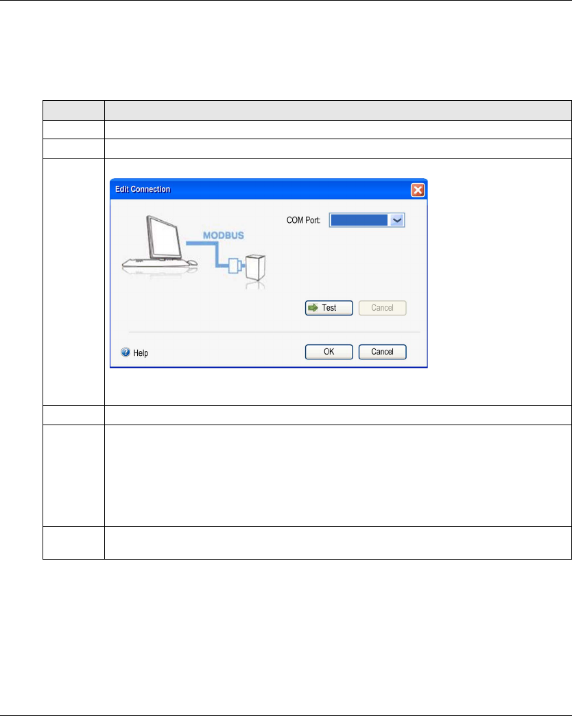
eXLhoist Configuration Software
182 EIO0000001505 04/2014
Edit a Connection
Overview
Follow the procedure to modify the communication settings for the connected device:
Step Action
1 Connect a Remote Device to the PC (see page 165).
2 From the main menu, select Communication → Edit Connection.
3 A window is displayed:
Select the COM Port.
4 Click Test.
5 If the communication is not established with the Remote Device, click Cancel and modify the
Modbus protocol settings.
Modbus Driver setting available:
Baud rate: 19200 bauds
Mode (Data Bits): RTU (8 bits)
Even Parity
One Stop bit
6 Click OK to validate and close the window.
Click Cancel to close the window.

eXLhoist Configuration Software
EIO0000001505 04/2014 183
Project Passwords Management
Overview
You can configure 2 passwords to the project:
The transfer password of the Configuration File
The project password
Transfer Password
The transfer password is asked before each Configuration File transfer.
After a modification of the system configuration (see page 140)
During a remote replacement (see page 207)
Follow the procedure to create or modified the transfer password:
The transfer password is stored in the project and in the Configuration File.
During configuration, use the keyboard of the PC to enter the transfer password.
In normal use (not connected to a PC), use the motion buttons 1...6 of the Remote Device to enter
the transfer password.
Step Action
1 From the main menu, select Device → Transfer Password → Create Password.
Result: A window is displayed.
The default transfer password is: 5, 6, 5, 6
2 To modify an existing password, enter the previous password in the Old Password fields.
3 Enter the new transfer Configuration File password in the New Password and in the Confirm
Password fields.
NOTE: Password must be 2 digits up to 6 digits.
Digits allowed are 1, 2, 3, 4, 5 and 6.
4 Click OK.

eXLhoist Configuration Software
184 EIO0000001505 04/2014
Project Password
The project password is asked before opening a locked project.
Follow the procedure to create or modified the project password:
If the project password is not entered at the opening project, select File → Password → Unlock
Project.
Step Action
1 From the main menu, select File → Password → Project Password.
Result: A window is displayed.
2 To modify an existing password, enter the previous password in the Old Password fields.
3 Enter the new project password in the New Password and in the Confirm Password fields.
NOTE: Password can contain from 1 to 20 characters.
Characters allowed are a…z, A…Z, and 0…9.
All other characters are non-allowed ( + ° _ - % ’ .).
4 Click OK.

eXLhoist Configuration Software
EIO0000001505 04/2014 185
Load the Configuration into the Remote Device
How To ...
Follow the procedure to load the configuration from the PC to the Remote Device:
Step Action
1 Connect a Remote Device to the PC (see page 165).
2 Create or open a project.
3 From the main menu, select Communication → Store to device.
4 If asked, enter the transfer password.
5 Wait during the transfer.

eXLhoist Configuration Software
186 EIO0000001505 04/2014
Save a Project
How To ...
Follow the procedure to save the project file on the PC:
It is possible to change the name of the project file by selecting File → Save as.
Step Action
1 From the main menu, select File → Save.
Result: A browser window is displayed.
2 Choose the directory.
3 Click Save.

eXLhoist Configuration Software
EIO0000001505 04/2014 187
Export to PDF
How To ...
Follow the procedure to export the configuration to a PDF file:
Step Action
1 From the main menu, select File → Export → Export to PDF.
Result: A browser window is displayed.
2 Choose the directory and the name of the export file.
3 Click Export.
Result: The export file is created.
4 A question window asks you to open or not the export file.
Click Yes to open the export file.
Click No to go back to the project workspace.

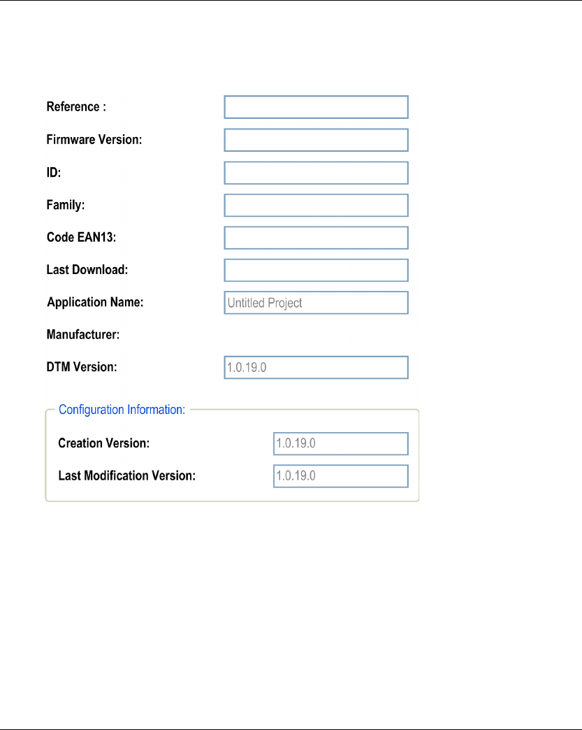
eXLhoist Configuration Software
EIO0000001505 04/2014 189
Device Identity
Overview
From this tab, you can read generic information from the Remote Device:

eXLhoist Configuration Software
190 EIO0000001505 04/2014
Description
At the activation, the fields are clear.
Click the Read button to display generic information coming from the connected Remote Device.
If there is no Remote Device connected, you are informed by a popup and all fields are cleared.
These information are updated and stored in the Remote Device after a download Configuration
File from PC.
Field Description
Reference Remote Device reference.
Firmware Version Firmware version of the Remote Device.
Format xxx.yyy (where xxx is major version and yyy is minor version).
ID ID of the Remote Device
Family eXLhoist
Code EAN13 Code EAN13 of the Remote Device.
ZART8L: 3606480610356
ZART8D: 3606480610363
ZART12D: 3606480610370
Last Download Date of the last load of a Configuration File in the Remote Device.
Application name Name of the project file (Last 30 characters).
Manufacturer www.schneider-electric.com
DTM Version Version of the DTM.
Configuration Information
Creation Version
Version of the eXLhoist Configuration Software used at the project creation
time (Never change after).
Configuration Information
Last Modification Version
Version of the eXLhoist Configuration Software used at the last project
modification time.
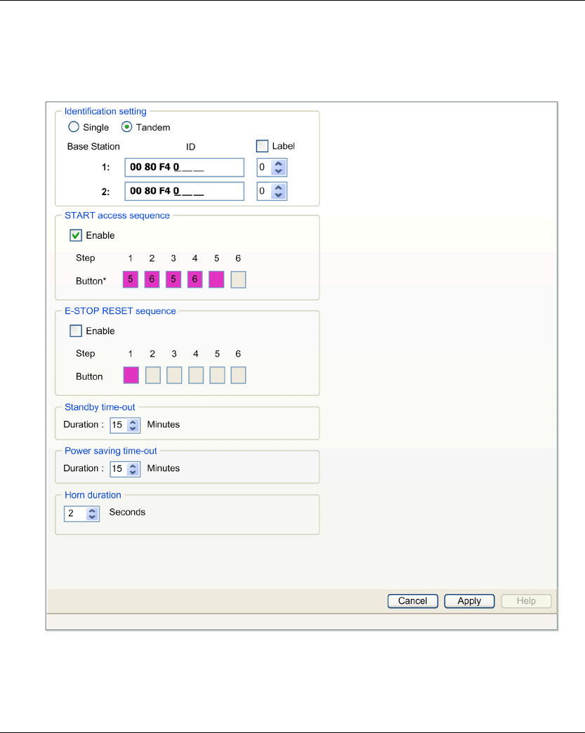
eXLhoist Configuration Software
EIO0000001505 04/2014 191
Parameters
Overview
In this tab, you can configure the Wireless Remote Control System parameters.

eXLhoist Configuration Software
192 EIO0000001505 04/2014
Identification Setting
You can select the Wireless Remote Control System configuration between:
SINGLE
TANDEM
You must enter the Base Station ID:
Format: 00 80 F4 0X XX XX (0X XX XX is an hexadecimal value from 0 00 00 to 3 FF FF).
This ID can be read on the Base Station.
Click Label checkbox to enable the label management. Select in the listbox a label number
(0…999). This label number is displayed on the ZART•D to identify the selected Base
Station/Bridge.
Start Access Sequence
The START access sequence is optional.
When START access sequence is enabled, the operator MUST enter this sequence to go in
START mode.
The START access sequence is enabled by default.
The default START access sequence is: 5, 6, 5, 6.
Click Enable checkbox to enable/disable it.
The allowed buttons for this sequence are 1, 2, 3, 4, 5, 6.
The sequence can have 1 to 6 steps.
Access sequence can use same button several times. For example: step 1 = 3 and step 4 = 3.
E-STOP RESET Sequence
The E-STOP RESET sequence is optional.
E-STOP RESET sequence is asked to the operator to reset the Remote Device after an E-STOP.
If reset sequence is empty or disable, the operator has to press the button 7 (trigger).
Click Enable checkbox to enable/disable it.
The allowed buttons for this sequence are 1, 2, 3, 4, 5, 6.
The sequence can have 1 to 6 steps.
E-STOP RESET sequence can use same button several times.
For example: step 1 = 3 and step 4 = 3.

eXLhoist Configuration Software
EIO0000001505 04/2014 193
Standby Time-out
The Remote Device goes automatically from START mode to STOP mode if no buttons are
pressed during the Standby Time-out delay.
You can modify the duration: 1…60 minutes.
The factory setting value is 15 minutes.
Power saving Time-out
When the Wireless Remote Control System is in STOP mode due to Standby Time-out, if no button
is pressed during this Power saving Time-out, the Remote Device automatically power OFF.
You can modify the duration: 1…300 minutes.
The factory setting value is 15 minutes.
Horn duration
This value is the Horn duration activation during the Start procedure.
You can modify the duration: 1…60 seconds.
The factory setting value is 2 seconds.
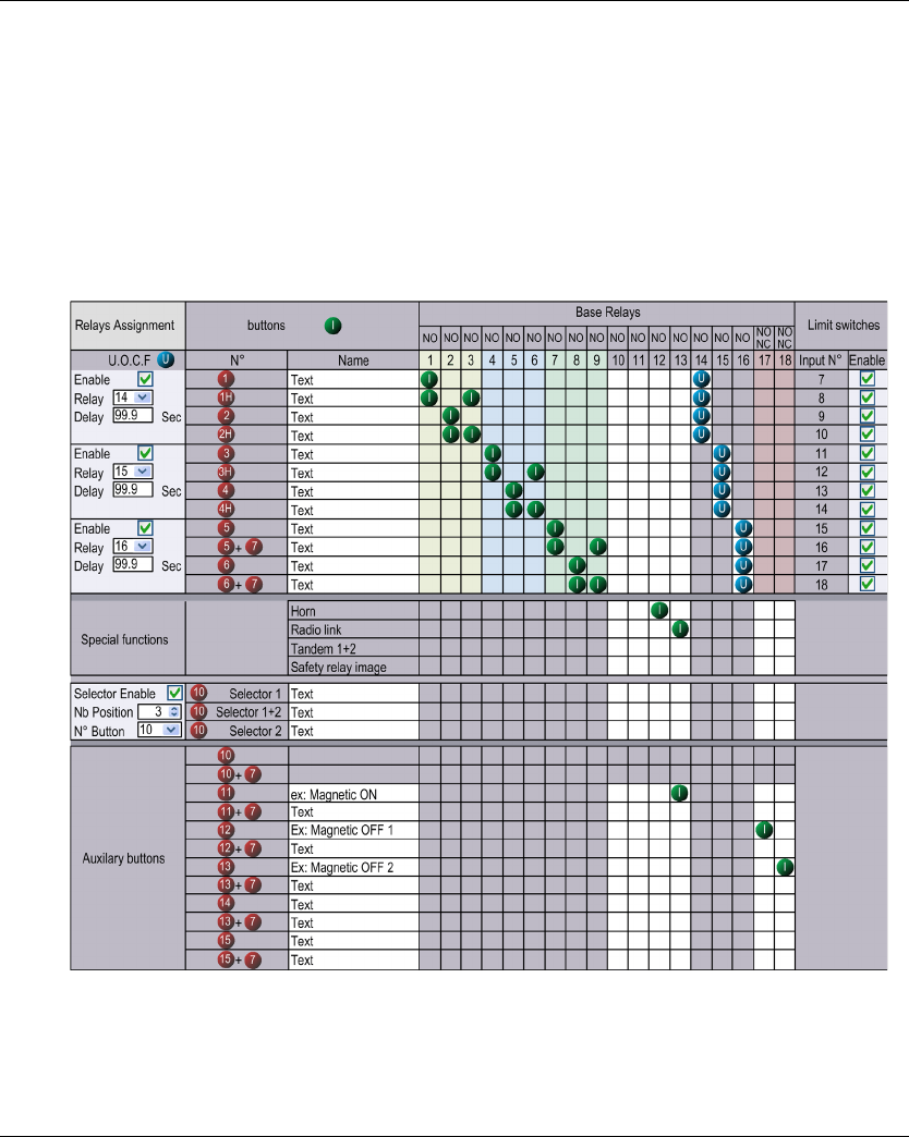
eXLhoist Configuration Software
194 EIO0000001505 04/2014
Relay Assignment
Overview
In this tab, you can:
Configure the motion buttons.
Configure a selector.
Configure the auxiliary buttons.
Configure UOC function.
Configure the limit switches.
Configure the special functions.
eXLhoist Configuration Software
EIO0000001505 04/2014 195
Restriction Due To Remote Device
This tab is automatically modified according to the selected/connected Remote Device:
Generic Description
The main use of this tab is to configure the association between the buttons and the relays.
To associate a button to a relay:
As long as the button is pressed, the associated relay(s) is(are) activated.
The cells in gray cannot be assigned.
4 relays maximum can be associated with the motion buttons (1…6+7).
Selector Configuration
The Selector configuration consists in:
In SINGLE configuration:
The selector is used to manage relays that are able to switch for example between 2 hooks or 2
trolleys
Reference Disable relay column Disable limit switches
group
Disable buttons rows
ZART8L 13...18 Yes 12…15+7
ZART8D - - 12…15+7
ZART12D - - -
Step Action
1 Click a cell to associate a button to a relay.
Result: The empty cell has now an associated symbol
2 To be more explicit, you can click in the Name text zone of a button to modify it (24 characters
maximum).
Step Action
1 Check the Selector Enable checkbox.
2 Select in the N° Button listbox the button to be used as selector.
For ZART8: it is possible to assign button 10...11 to the selector.
For ZART12: it is possible to assign button 10...15 to the selector.
3 Select 2 or 3 in the Nb Position combobox.
4 Click a cell to associate a relay to a selector position.
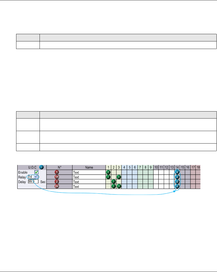
eXLhoist Configuration Software
196 EIO0000001505 04/2014
In TANDEM configuration:
In this configuration, no any relays are used.
The selector is used to select Base Station to be piloted.
The Use a Selector checkbox is checked and not modifiable.
The Number of position field is set to 3 and is not modifiable.
The relay assignment is the same for the 2 Base stations.
UOC Configuration
The UOC configuration consists in associate a motion axis to a relay.
This relay can be wired to the DRIVE Safe Torque Off (STO) or in serial with a contactor coil.
For example:
The relay 14 is ON when one or more of relays 1, 2, 3 is ON.
When relays 1, 2 and 3 are OFF, the UOC delay starts.
The relay 14 goes OFF when the UOC delay is expired.
For more details, refer to UOC description (seepage105).
NOTE: This functionality is available in the complete version of the eXLhoist Configuration
Software.
Step Action
1 Select, in the N° Button combobox, the button to be used as selector.
Step Action
1 Click the UOC Enable checkbox.
Note: There is an UOC function for the 3 axis.
2 Select the associated relay in the Relay combobox.
Result: Corresponding cells are automatically filled by a (U) symbol.
3 Enter the UOC delay (0…99.9 seconds).
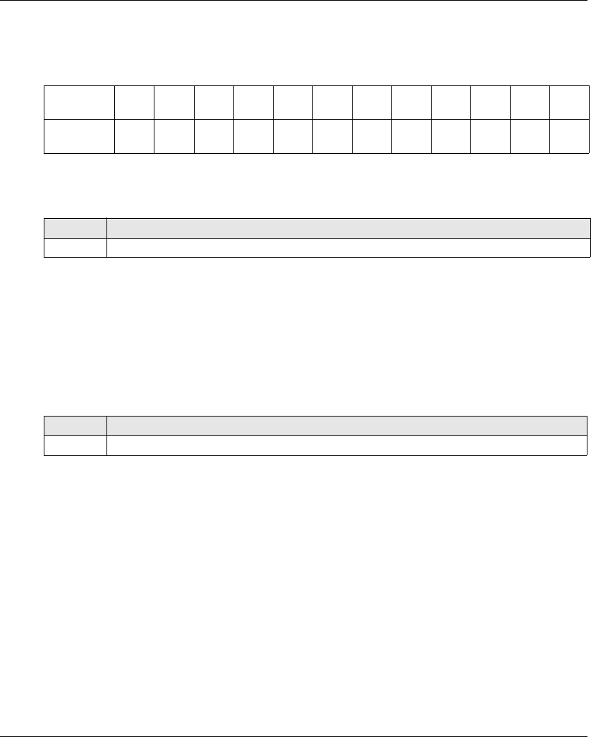
eXLhoist Configuration Software
EIO0000001505 04/2014 197
Safeguarding Function Configuration
The Safeguarding function configuration consists in enable/disable the limit switches.
The association between motion buttons and limit switch inputs are unmodifiable:
When the limit switch is activated, the associated motion button is considered as unpressed and
the associated relays are switched OFF.
For more details, refer to limit switches description (see page 107).
NOTE: This functionality is available in the complete version of the eXLhoist Configuration
Software.
Special Functions Configuration
The special functions configuration consists in associate a special function to a relay.
The 4 special functions are:
Horn
Radio link
TANDEM 1+2
Safety relay image
For more information, refer to special functions description (see page 109).
Motion
button
11H22H33H44H55+766+7
Limit switch
input
IN7 IN8 IN9 IN10 IN11 IN12 IN13 IN14 IN15 IN16 IN17 IN18
Step Action
1 Check the Enable checkbox of an input N° (Input 7...input 18).
Step Action
1 For each of the 4 special functions, click a cell to associate a relay.
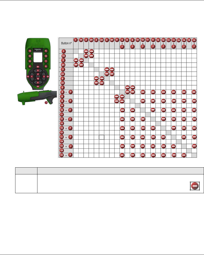
eXLhoist Configuration Software
198 EIO0000001505 04/2014
Interlocking
Overview
In this tab, you can configure the buttons combinations that cannot operate simultaneously.
Example of the factory setting:
The button 1 and 2 are associated to the same axis, for the opposites directions.
The button 1 must not operate while the button 2 is pressed.
The button 2 must not operate while the button 1 is pressed.
If the buttons are pressed simultaneously, the movement is stopped.
Step Action
1 Click a cell to interlock (or not) 2 buttons (or buttons combinations).
Result: When the buttons are interlocked, the empty cell has now an associated symbol .
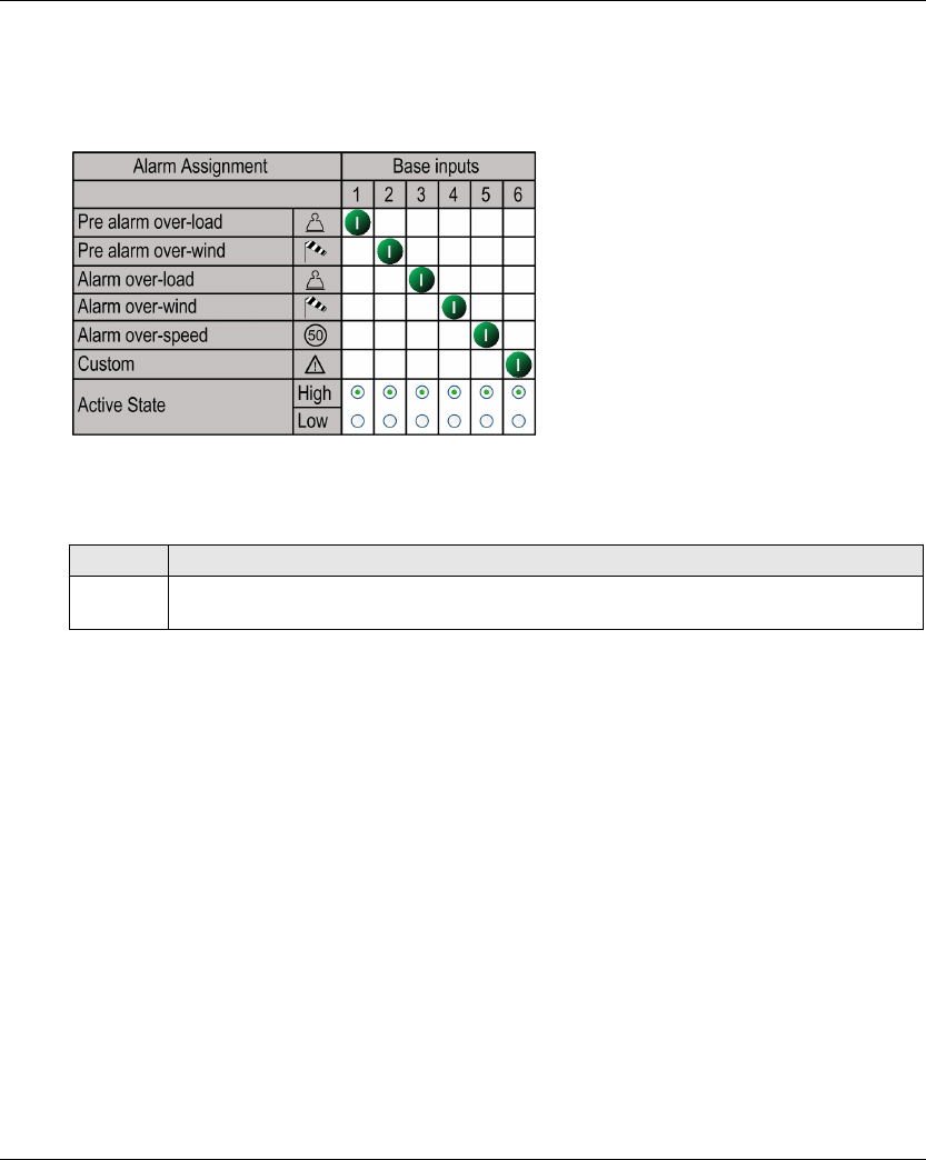
eXLhoist Configuration Software
EIO0000001505 04/2014 199
Detected Applicative Alarms
Overview
In this tab, you can configure the Applicative Alarm states.
The Base Station can provide detected alarms information to the ZART•D.
Voltage free sensors can be connected to Base Station.
For more information, refer to Special functions description (see page 103).
Step Action
1 Click High or Low to select the active state of each alarm.
With a NO type switch, select High.

eXLhoist Configuration Software
200 EIO0000001505 04/2014

EIO0000001505 04/2014 201
Harmony eXLhoist
Maintenance / Device Replacement
EIO0000001505 04/2014
Maintenance / Device Replacement
Chapter 8
Maintenance / Device Replacement
What Is in This Chapter?
This chapter contains the following sections:
Section Topic Page
8.1 Maintenance 202
8.2 Device Replacement 203
8.3 Remote Device Resets 211

Maintenance / Device Replacement
202 EIO0000001505 04/2014
Maintenance
Section 8.1
Maintenance
Regular Cleaning
Remote Device Cleaning
When the surface or the frame of the display gets dirty, soak a soft cloth in water with a neutral
detergent, wring the cloth tightly, and wipe the display.
Periodic Check Points
Annual check point for the ZARB•W Base Station: check the good terminal block tightening.
For more information, refer to the Safety chapter (seepage53).
NOTICE
EQUIPMENT DAMAGE
Do not use paint thinner, organic solvents, or a strong acid compound to clean the equipment.
Failure to follow these instructions can result in equipment damage.
Maintenance / Device Replacement
EIO0000001505 04/2014 203
Device Replaceme nt
Section 8.2
Device Replacement
Overview
The Configuration File management allows some device replacement, without tool.
What Is in This Section?
This section contains the following topics:
Topic Page
Base Station Replacement 204
ZART•D Replacement 207
ZART8L Device Replacement 210
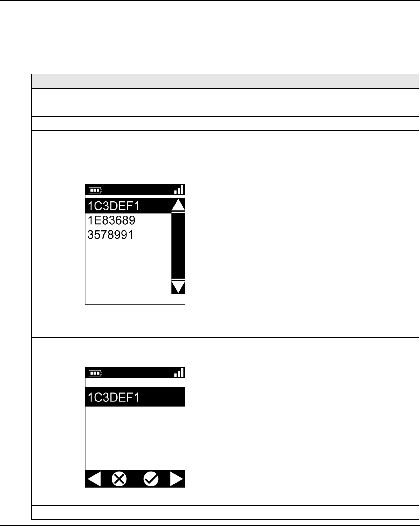
Maintenance / Device Replacement
204 EIO0000001505 04/2014
Base Station Replacement
New Base Station Replacement
Follow the procedure to replace a Base Station by a new one:
Step Action
1 Execute a Remote Pairing Reset (see page 211).
2 Install the new Base Station.
3 Power ON the new Base Station.
4 Place yourself with the Remote Device to an appropriate distance from the Base Station (around
10 m (32.8 ft)).
5 Press only the ON/START/Horn button on the Remote Device more or equal than 1 s.
Result: The Remote Device displays the ID list of detected Base Station:
6 Selects the ID of the new Base Station with buttons 5 and 6.
7 Press the button 7 (trigger) to validate.
Result:
8 Select the validation cell (check symbol) with buttons 1 and 2.
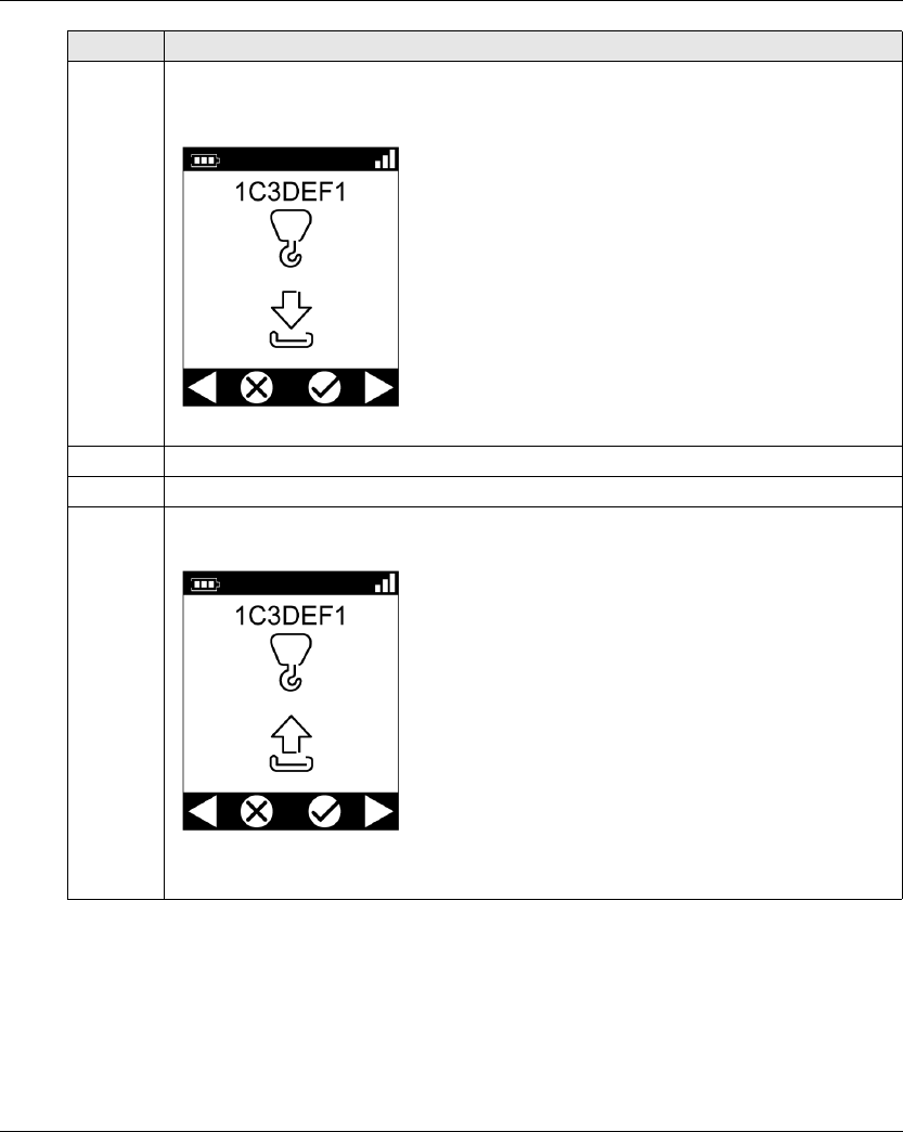
Maintenance / Device Replacement
EIO0000001505 04/2014 205
9 Press the button 7 (trigger) to validate.
Result: The Remote Device propose to load the Configuration File from the Base Station to the
Remote Device.
10 Select the cancel cell (X) with buttons 1 and 2.
11 Press the button 7 (trigger) to validate.
12 The Remote Device propose to load the Configuration File from the Remote Device to the Base
Station.
Select the validation cell (check symbol) with buttons 1 and 2.
Step Action

Maintenance / Device Replacement
206 EIO0000001505 04/2014
Result: The Wireless Remote Control System is in STOP mode (see page 123).
It is recommended to do again an Acceptance Test (see page 75).
13 If the Configuration File has a transfer password, a padlock is displayed:
Enter the Configuration File transfer code with the buttons 1 to 6.
The default transfer password is 5, 6, 5, 6.
14 Press the button 7 (trigger) to validate.
Result: The Remote Device loads the Configuration File from the Remote Device to the Base
Station.
15 Wait for the end of the Configuration File load.
Step Action
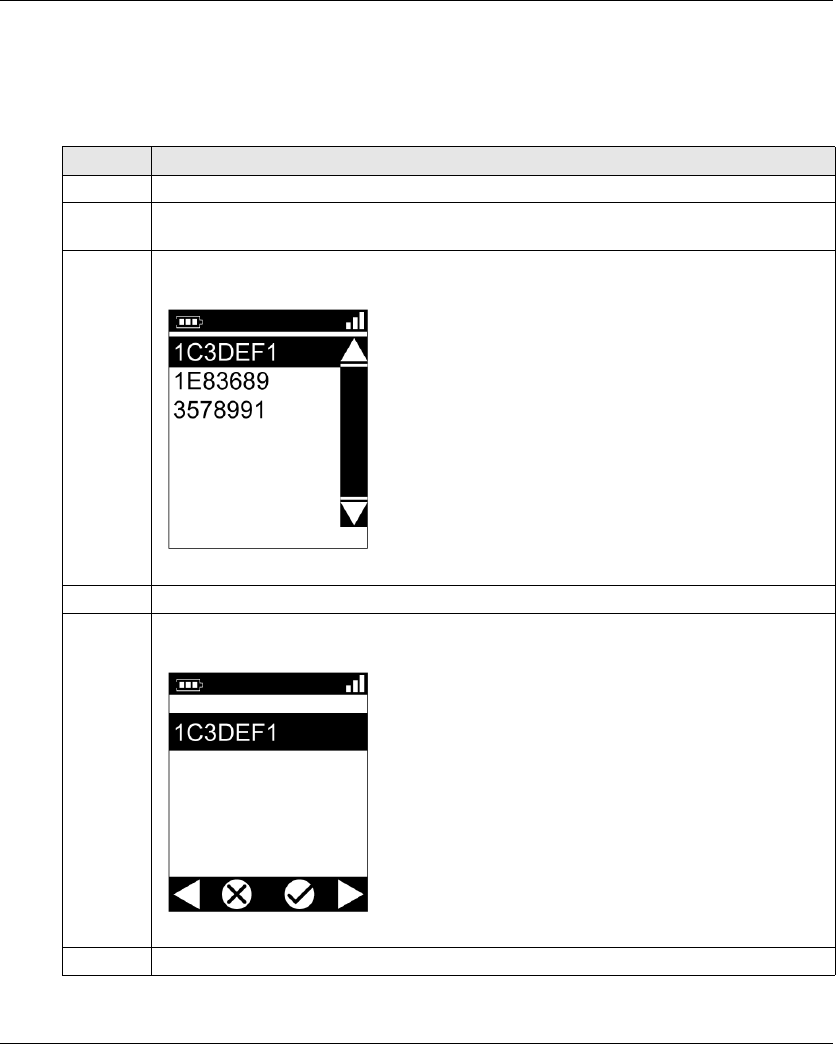
Maintenance / Device Replacement
EIO0000001505 04/2014 207
ZART•D Replacement
Replacement of a ZART•D by an out-of-the-box One
Procedure to replace an out of work ZART•D by an out-of-the-box one:
Step Action
1 Power ON the Base Station.
2 Place yourself with the Remote Device to an appropriate distance from the Base Station (around
10 m (32.8 ft)).
3 Press only the ON/START/Horn button on the Remote Device more or equal than 1 s.
Result: The Remote Device displays the ID list of detected Base Station:
4 Selects the ID of the appropriate Base Station with buttons 5 and 6.
5 Press the button 7 (trigger) to validate.
Result:
6 Select the validation cell (check symbol) with buttons 1 and 2.

Maintenance / Device Replacement
208 EIO0000001505 04/2014
Result: The Wireless Remote Control System is in Stop mode (see page 123).
It is recommended to do again an Acceptance Test (see page 75).
7 Press the button 7 (trigger) to validate.
Result: The Remote Device propose to load the Configuration File from the Base Station to the
Remote Device.
8 Select the validation cell (check symbol) with buttons 1 and 2.
9 Press the button 7 (trigger) to validate.
Result: The Remote Device loads the Configuration File from the Base Station to the Remote
Device.
10 Wait for the end of the Configuration File load.
Step Action

Maintenance / Device Replacement
EIO0000001505 04/2014 209
Replacement of a ZART•D by an Already Configured One
Replacement of an out of work ZART•D by an already configured one:
Step Action
1 Do a Remote Factory Reset (see page 211).
2 Execute the procedure Replacement of an out of Work ZART•D by a New One (see page 207).

Maintenance / Device Replacement
210 EIO0000001505 04/2014
ZART8L Device Replacement
Replacement of an ZART8L
Procedure to replace an out of work ZART8L:
Result: The Remote Device goes to STOP mode (see page 123).
It is recommended to redo an Acceptance Test (see page 75).
Step Action
1 Connect the Remote Device to a PC (see page 165).
2 Start the eXLhoist Configuration Software (see page 178).
3 Open an existing project (see page 180).
4 Select Communication → Store to Device.
5 Wait for the end of the Configuration File load in the Remote Device.
6 Disconnect the Remote Device to the PC.
7 Power ON the Base Station.
8 Power ON the Remote Device.
9 The Configuration File is automatically loaded from the Remote Device to the Base Station.
During the load, the START LED and “2” LED are flashing.
Wait for the end of the Configuration File load.
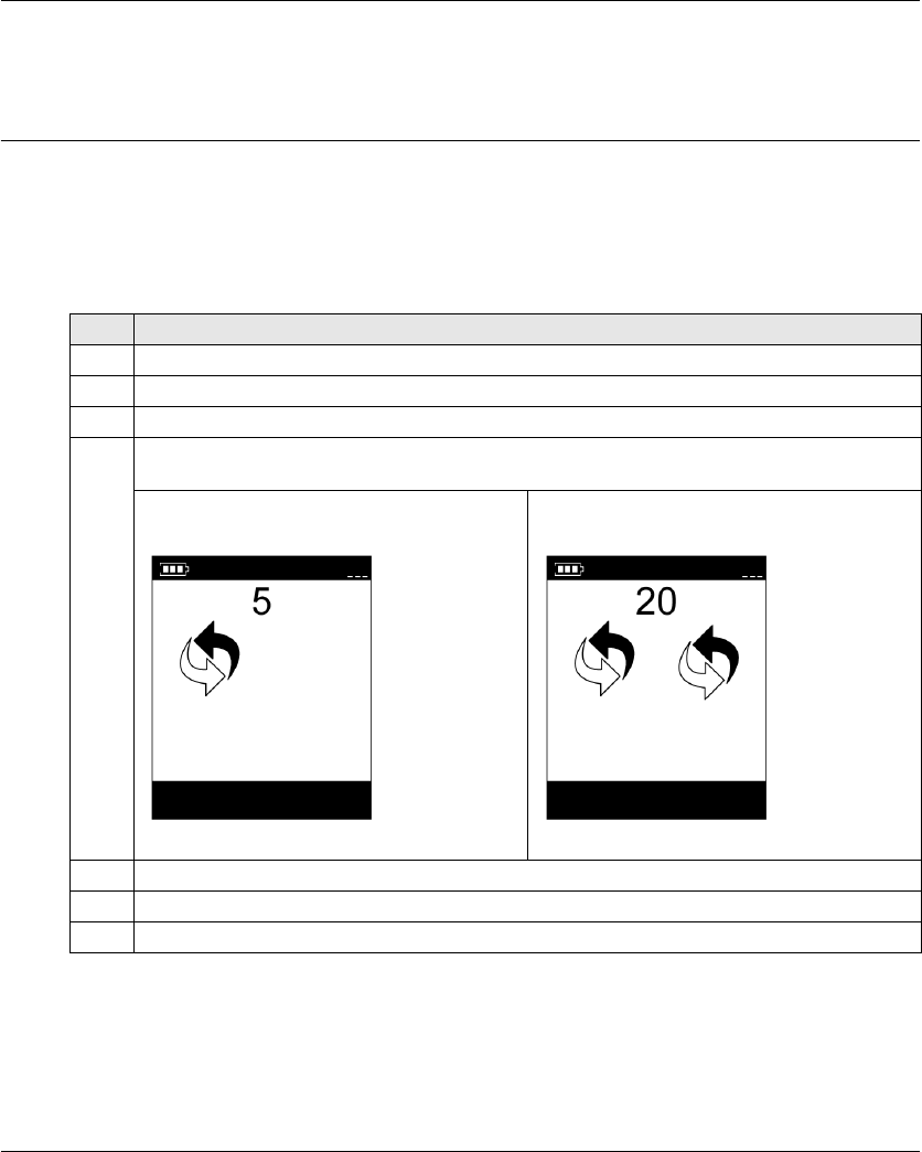
Maintenance / Device Replacement
EIO0000001505 04/2014 211
Remote Device Resets
Section 8.3
Remote Device Resets
Remote Device Resets
Procedure
Step Action
1 Power ON the Remote Device.
2 On the rear of the Remote Device, unscrew the 2 screws.
3 Remove the cover.
4 Press and maintain the reset button for the appropriate duration (see page 212).
For the ZAR•D:
When the first delay is reached (for Pairing reset),
the remote displays:
When the second delay is reached (for Factory
reset), the remote displays:
5 Release the reset button.
5 Place back the cover.
6 Screw the 2 screws to mount the cover.
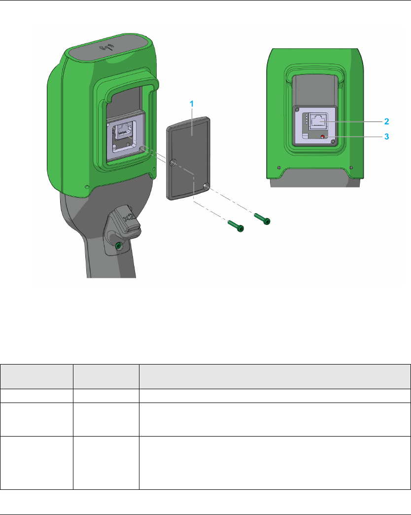
Maintenance / Device Replacement
212 EIO0000001505 04/2014
Remote Device rear view:
1 Cover
2 RJ45 connector
3 Reset button
Reset Information
Title t = Reset button
duration press
Remote Device reaction
Simple reset t < 5 s Remote Device reboot.
Pairing reset 5 s ≤ t < 20 s Remote Device reboot.
Erase in the remote memory the stored Base Station ID. The remote is no
more paired with Base Station.
Factory reset t > 20 s Remote Device reboot.
Erase in the remote memory the stored Base Station ID. The remote is no
more paired with Base Station.
Delete the Configuration File. The Remote Device goes back to factory
settings.

EIO0000001505 04/2014 213
Harmony eXLhoist
EIO0000001505 04/2014
Appendices

214 EIO0000001505 04/2014

EIO0000001505 04/2014 215
Harmony eXLhoist
Architecture Examples
EIO0000001505 04/2014
Architecture Examples
Appendix A
Architecture Examples
What Is in This Chapter?
This chapter contains the following topics:
Topic Page
Tested Architectures 216
Vacuum/Magnetic Application Example 221
Room Lighting Application Example 224
Architecture Examples
216 EIO0000001505 04/2014
Tested Architectures
Overview
Schneider Electric provides the basis of tested architecture. You can adapt these architectures to
your individual requirements. NOTE: the architectures specified have been tested under actual
service conditions. Your specific application requirements may be different from those assumed
for these projects. In that case, you have to adapt the architecture to your particular needs. To do
so, you need to consult the specific product documentation that you may find necessary to modify
or adapt. Pay particular attention and conform to any safety information, different electrical
requirements, and normative standards that would apply to your modifications and/or adaptations.
Some or all of the architectures may contain recommendations of products that are not available
in your country or locality, or may imply or recommend wiring, products, procedures, or controller
logic and/or functions that are in conflict with your local, regional, or national electrical or safety
codes and/or normative standards.
The use and application of the architectures require expertise in the design of control systems.
Only you, the designer or integrator, can be aware of all the conditions and factors present during
installation and setup, operation, and maintenance of the machine or process, and can therefore
determine the associated equipment, the functions, the related safety provisions and interlocks
which can be effectively and properly used. When selecting control equipment, and any other
related equipment or software for a particular application, you must also consider any applicable
local, regional, or national standards and/or regulations.
WARNING
REGULATORY INCOMPATIBILITY
Be sure that all equipment applied and systems designed comply with and conform to all
applicable local, regional, and national regulations and standards.
Failure to follow these instructions can result in death, serious injury, or equipment
damage.
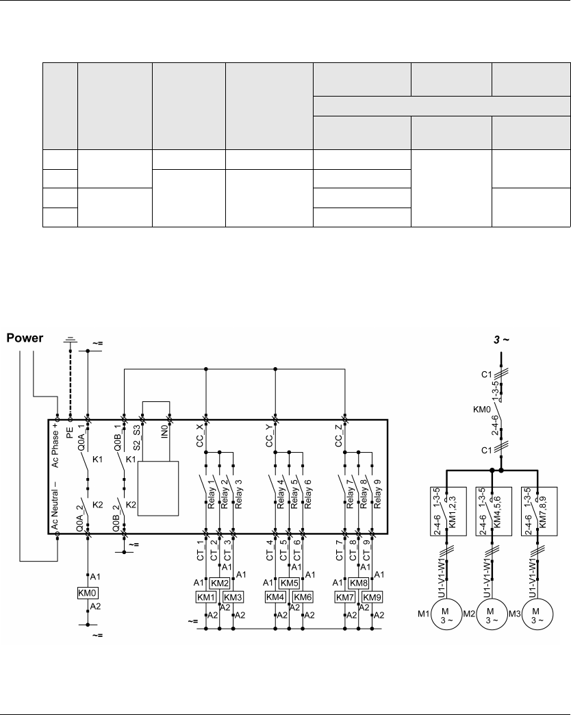
Architecture Examples
EIO0000001505 04/2014 217
Description
Schneider Electric has tested some possible architectures:
Stop category depends on the UOC function/wiring (see page 105).
E-Stop and Stop SIL level depends on the IN0 and S2_S3 wiring (see page 111).
Safety Case 1
S1 is a wired E-STOP SIL2;
The E-STOP of the Remote Device is SIL2.
No. Hoisting Trolley Translation E-STOP
STOP
Motion Stop
category
According To
EN 61508
EN 13849
EN 61508
EN 13849
EN60204
1Contactor Contactor Contactor SIL2/Cat 3
SIL1/Cat 2
Cat 0
2
ATV32 ATV32
SIL3/Cat 4
3ATV71 SIL3/Cat 4 Cat 1
4 SIL3/Cat 4
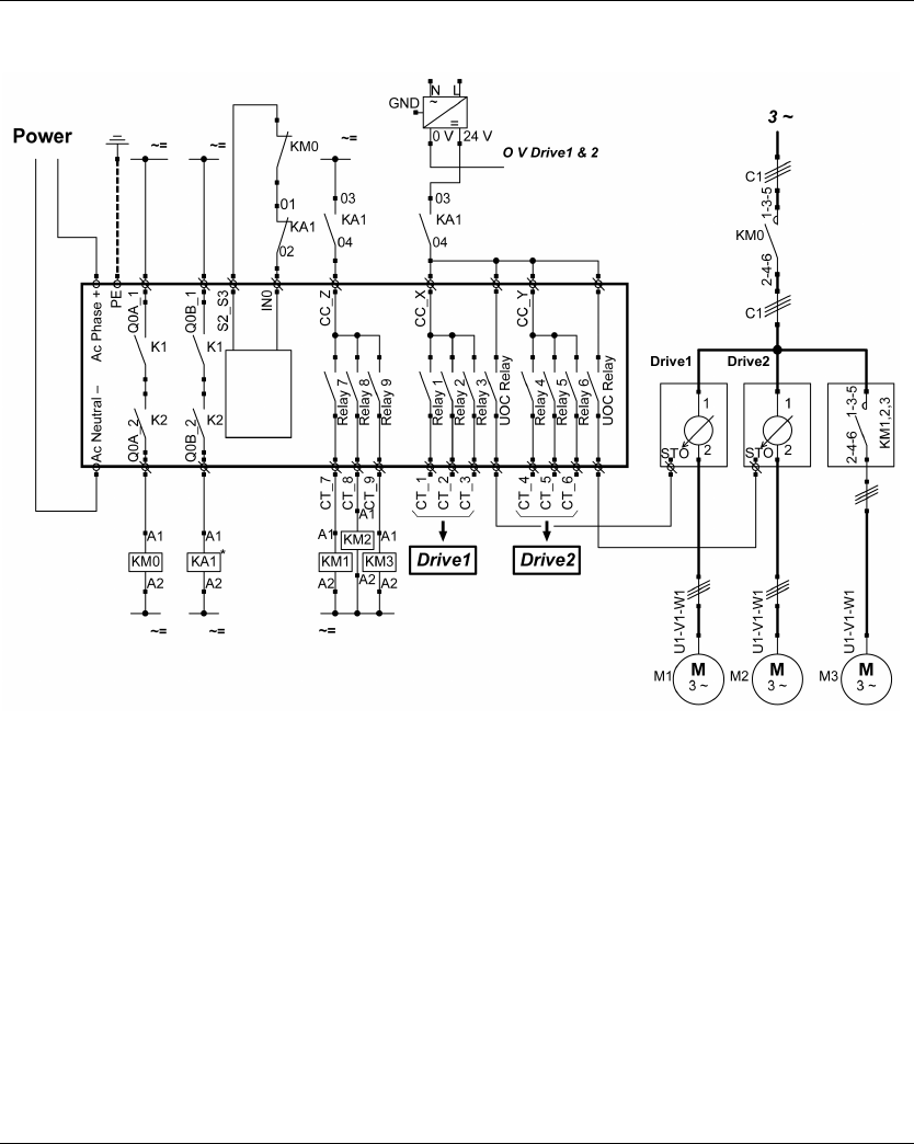
Architecture Examples
218 EIO0000001505 04/2014
Safety Case 2
S1 is a wired E-STOP SIL2;
The E-STOP of the Remote Device is SIL3.
Drive1 and Drive2 are motor drives
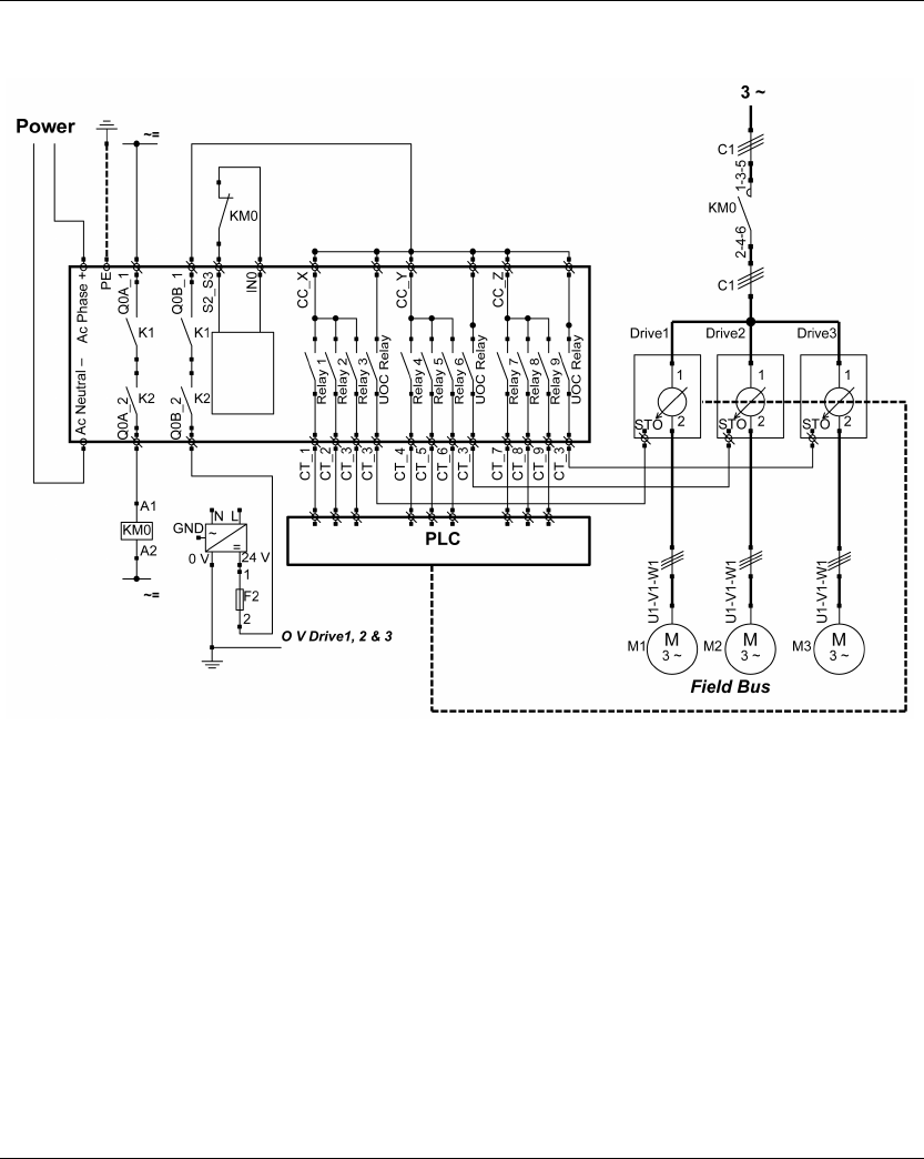
Architecture Examples
EIO0000001505 04/2014 219
Safety Case 3
S1 is a wired E-STOP SIL2;
The E-STOP of the Remote Device is SIL3.
Drive1, Drive2, and Drive3 are motor drives
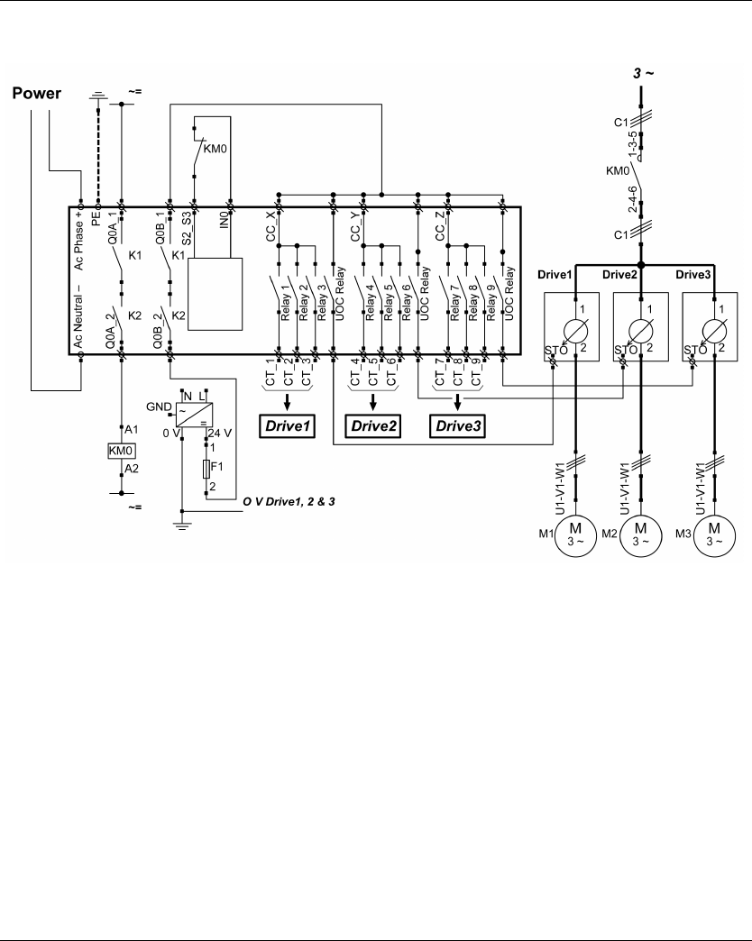
Architecture Examples
220 EIO0000001505 04/2014
Safety Case 4
S1 is a wired E-STOP SIL2;
The E-STOP of the Remote Device is SIL3.
Drive1, Drive2, and Drive3 are motor drives
Architecture Examples
EIO0000001505 04/2014 221
Vacuum/Magnetic Application Example
Description
A possible use of auxiliary buttons is a Vacuum/Magnetic function.
Configuration
Example of system configuration
As already done in the factory setting, it is recommanded to use buttons at different sides of
Remote Device for load release function (operator uses both hands).
Vacuum/Magnetic Description
Triggering “Vacuum/Magnetic ON“ button is assigned to 1 relay.
When the operator presses the “Vacuum/Magnetic ON” button, the magnetic is activated
through the associated relay.
Releasing To release the load, simultaneously press ”Vacuum/Magnetic OFF 1” and “Vacuum/Magnetic
OFF 2” buttons.
“Vacuum/Magnetic OFF 1” button should be assigned to 1 NO+NC relay.
“Vacuum/Magnetic OFF 2” button should be assigned to 1 different NO+NC relay.
Topic Configured button Associated relay
Vacuum/Magnetic ON 13 Q16
Vacuum/Magnetic OFF 1 14 Q17
Vacuum/Magnetic OFF 1 15 Q18
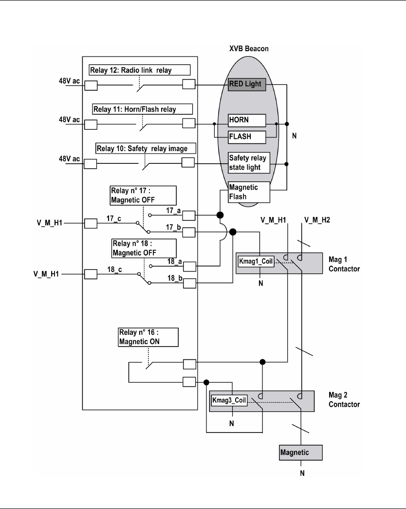
Architecture Examples
222 EIO0000001505 04/2014
Wiring Example
V_M_H1 V hold command magnetic 48…230 Vac
V_M_H2 V hold power magnetic 48…230 Vac

Architecture Examples
EIO0000001505 04/2014 223
NOTE:
The Magnetic OFF flash is ON only in the 2 following cases:
When the operator presses at least one of the Magnetic OFF buttons.
If one the Magnetic OFF relay is welded. In this case, a maintenance action shall be done
(Otherwise it is enough to press the other Magnetic OFF button for releasing the load).
The power supply choice is the OEM responsibility. It depends on the risk analysis.
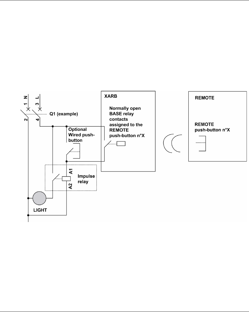
Architecture Examples
224 EIO0000001505 04/2014
Room Lighting Application Example
Description
It is possible to manage room lighting applications. An auxiliary button commands an impulse relay
on the room lighting circuit.
Configuration
There is no specific configuration needed. You have to associate an auxiliary button to a relay.
Wiring Example
NOTE: Schneider Electric offers modular impulse relays which are bistable switches designed to
control load power mainly for lighting applications.

EIO0000001505 04/2014 225
Harmony eXLhoist
Glossary
EIO0000001505 04/2014
Glossary
A
AWG
(American wire gauge) The standard that specifies wire section sizes in North America
C
CCF
(Common Cause of Failure)
CSA
(Canadian standards association) The Canadian standard for industrial electronic equipment in
hazardous environments.
D
DTM
(Device Type Manager) Classified into 2 categories:
Device DTMs connect to the field device configuration components.
CommDTMs connect to the software communication components.
The DTM provides a unified structure for accessing device parameters and configuring, operating,
and diagnosing the devices. DTMs can range from a simple graphical user interface for setting
device parameters to a highly sophisticated application capable of performing complex real-time
calculations for diagnosis and maintenance purposes.
E
E-STOP
Emergency stop (according to EN ISO13850:2008) function that is intended to:
avert arising, or reduce existing, hazards to persons, damage to machinery or to work in
progress,
be initiated by a single human action.
EMC
ElectroMagnetic Compatibility
EN
EN identifies 1 of many European standards maintained by CEN (European Committee for
Standardization), CENELEC (European Committee for Electrotechnical Standardization), or ETSI
(European Telecommunications Standards Institute).

Glossary
226 EIO0000001505 04/2014
F
FE
(Functional Earth) A common grounding connection to enhance or otherwise allow normal
operation of electrically sensitive equipment (also referred to as functional ground in North
America).
In contrast to a protective Earth (protective ground), a functional earth connection serves a purpose
other than shock protection, and may normally carry current. Examples of devices that use
functional earth connections include surge suppressors and electromagnetic interference filters,
certain antennas, and measurement instruments.
Firmware
The operating system (OS) of a device
H
hex
(hexadecimal)
HFT
(Hardware Fault Tolerance)
I
IEC
(International Electrotechnical Commission) A non-profit and non-governmental international
standards organization that prepares and publishes international standards for electrical,
electronic, and related technologies.
IP
(Ingress Protection) The protection classification according to IEC 60529.
L
LED
(Light Emitting Diode) An indicator that illuminates under a low-level electrical charge.

Glossary
EIO0000001505 04/2014 227
M
MAC address
(Media Access Control address) A unique 48-bit number associated with a specific piece of
hardware. The MAC address is programmed into each network card or device when it is
manufactured.
MTTF
(Mean TIme To Failure)
N
NC
(Normally Closed) A contact pair that closes when the actuator is de-energized (no power is
applied) and opens when the actuator is energized (power is applied).
NEMA
(National Electrical Manufacturers Association) The standard for the performance of various
classes of electrical enclosures. The NEMA standards cover corrosion resistance, ability to help
protect from rain, submersion, and so on. For IEC member countries, the IEC 60529 standard
classifies the ingress protection rating for enclosures.
NO
(Normally Open) A contact pair that opens when the actuator is de-energized (no power is applied)
and closes when the actuator is energized (power is applied).
P
PC
(Personal Computer)
PELV
(Protective Extra Low Voltage)
PFD
(Probability of Failure on Demand)
PL
(Performance Level)
PST
(Process Safety Time)

Glossary
228 EIO0000001505 04/2014
R
RJ45
A standard type of 8-pin connector for network cables.
S
SELV
(Safety Extra Low Voltage) A system that follows IEC 61140 guidelines for power supplies is
protected in such a way that voltage between any 2 accessible parts (or between 1 accessible part
and the PE terminal for class 1 equipment) does not exceed a specified value under normal
conditions or under inoperable conditions.
SFF
(Safe Failure Fraction)
SIL
(Safety Integrity Level) (according to IEC 61508)
START warning time
Time between the STOP mode and START mode. During this time, the Horn is activated, the
motion and auxiliary function are not enabled.
STO
(Safe Torque Off).
U
UL
(Underwriters Laboratories) A US organization for product testing and safety certification.
UOC
(Unintended Operating Control) The UOC function allows control of a drive STO input.