Schneider Electric Systems Canada MR450-X003 FM Radio Modem User Manual M Series
Trio Datacom Pty Ltd (a wholly owned company of Schneider Electric) FM Radio Modem M Series
UserManual.wiki
>
Schneider Electric Systems Canada
>
MR450-X003 User Manual
>
User Manual
Contents
1.
User Manual
2.
Quick Start Guide
User Manual
Navigation menu
Upload a User Manual
Namespaces
Wiki Guide
HTML
PDF
Info
Views
User Manual
Discussion / Help
Navigation
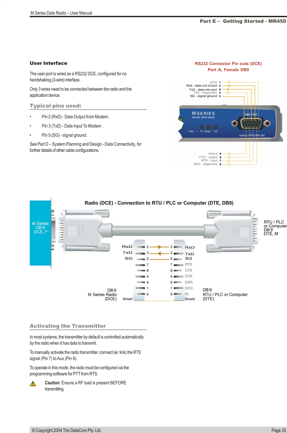
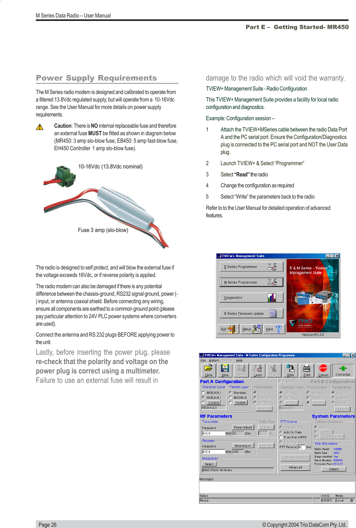
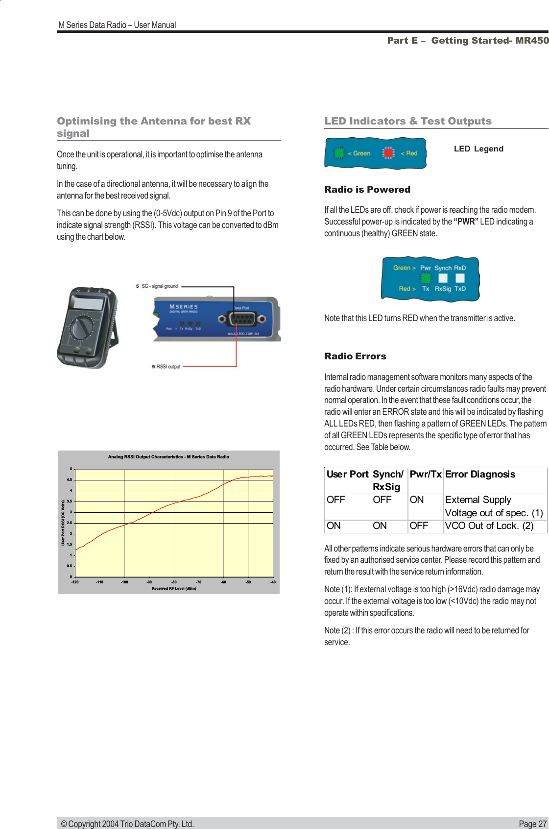
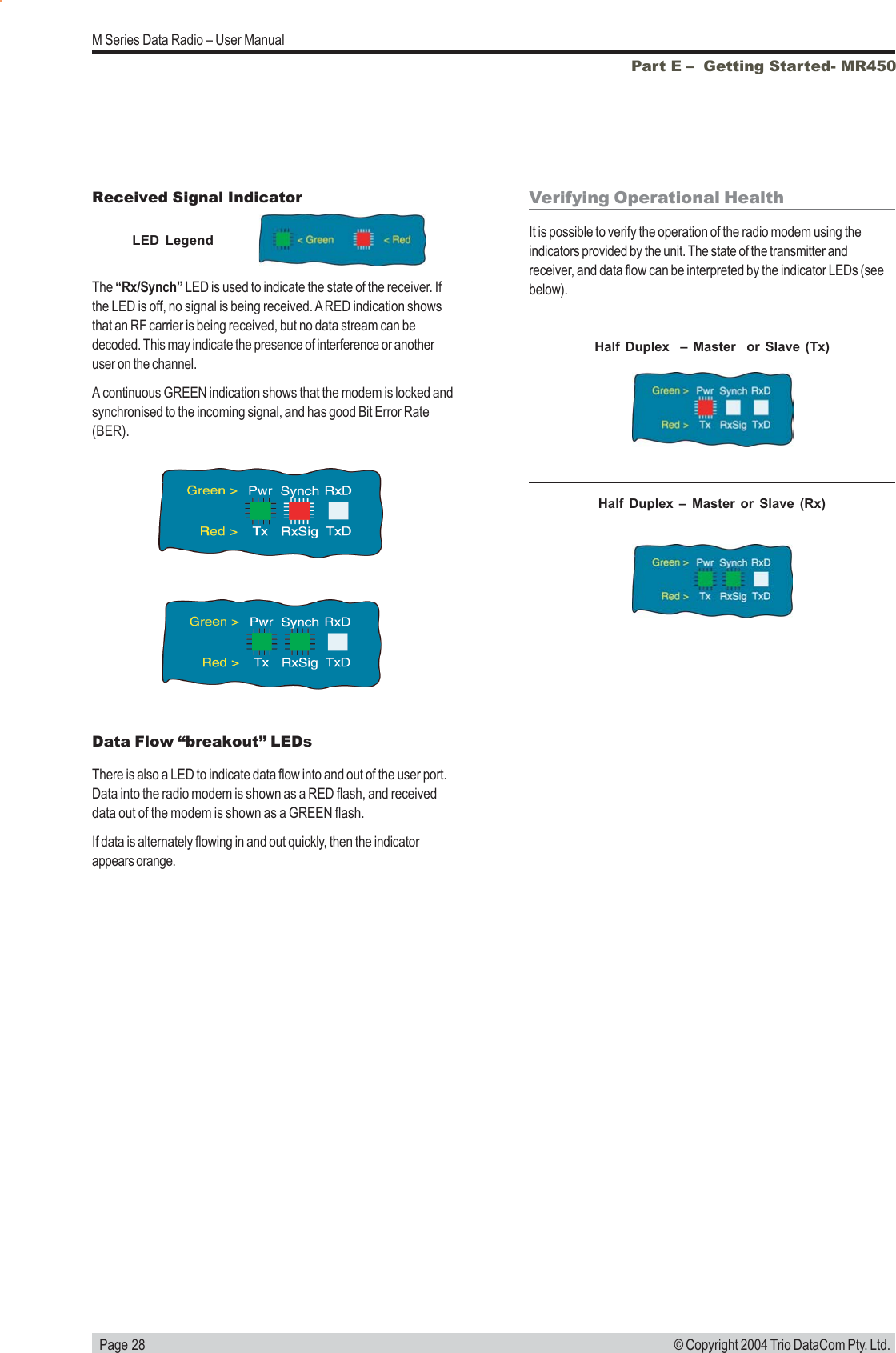
![Page 7M Series Data Radio – User Manual © Copyright 2004 Trio DataCom Pty. Ltd.Model Number CodesPart B – M Series OverviewD, E, S & M Series Data Radios - Part Number Matrix = Tyxxx-aabbb-cdeT y xxx-aa bbb-cd eOptions - Base Stations*Options - Hot Standby Configurations*0= No Options 0= No OptionsDuplexerAntenna1= 450MHz Band Reject Typically Internal [DUPLX450BR]Number Type Antenna ConfigAntenna Type2= 450MHz Band Reject (<9MHz split)[DUPLX450BR/5]A- - - Separate Tx & Rx3= 450MHz Band Pass [DUPLX450BP]B- - Dual [x4] Separate Tx & Rx4= 900MHz Band Reject Typically Internal [DUPLX900BR]CSingle Internal Single Combined Tx/Rx5= 900MHz Band Pass [DUPLX900BP]DDual [x2] Internal Dual [x2] Combined Tx/Rx6= 900MHz Band Pass (76MHz split)[DUPLX852/930]ESingle External Single Combined Tx/RxFDual [x2] External Dual [x2] Combined Tx/RxNote: Specify Internally or Externally fitted. Externally fitted duplexes require feeder tails.Options*0= No OptionsD= Diagnostics - [DIAGS/D, DIAGS/DH, DIAGS/E or DIAGS/EH, DIAGS/M] (D, E & M Series Only)E= Hazardous Environment Class 1, Div 2 and Diagnostics [HAZ-APROVAL/M + DIAGS/M] (M Series)N= Remote Fitted into NEMA Enclosure [NEMA 4/R]F= Full Duplex Operation [ERFD450] (ER450 only)X= Full Duplex Operation [ERFD450 & DIAGS/E] (ER450 only)S= SMA Connector (SR450 Remote Only)RF Channel Data Rate & Bandwidth (Internal ModemD SeriesE SeriesA01= ACA 4800bps 12.5kHz001= 12.5kHz (No Modem Fitted)A01= ACA 4800#/ 9600bps 12.5Hz001= 2400bps 12.5KHz / 4800bps 25kHzA02= ACA 9600bps 25kHz002= 25kHz (No Modem Fitted)A02= ACA 9600#/ 19k2bps 25kHz002= 4800bps 12.5KHz / 9600bps 25kHzF01= FCC 9600bps 12.5kHz241= 2400bps in 12.5kHz [24SR]*F01= FCC 9600#/ 19K2bps 12.5kHz003= FCC 9600bps 12.5KHz242= 2400bps in 25kHz [24SR]*F02= FCC 19k2bps 25kHz482= 4800bps in 25kHz [48SR]*E01= ETSI 9600bps 12.5kHzE02= ETSI 19k2bps 25kHzFrequency (200 & 400 MHz Bands)Frequency (800 & 900 MHz Band) (D & S Series Only)39= 208 to 240MHz (Tx & Rx)07= (Tx) 847 to 857MHz (Rx) 923 to 933MHz (D Series only, 1W Full Duplex46= 370 to 388MHz (Tx & Rx)10 = (Tx) 848 to 858MHz (Rx) 920 to 934MHz47= 380 to 396MHz (Tx & Rx)06= (Tx) 923 to 933MHz (Rx) 847 to 857MHz (D Series only, 1W Full Duplex48 = 395 to 406MHz (Tx & Rx)11 = (Tx) 920 to 934MHz (Rx) 848 to 858MHz50 = 403 to 417MHz (Tx & Rx)12= 855 to 860MHz (Tx & Rx)58 = (Tx) 406 to 421MHz (Rx) 415 to 430MHz14 = (Tx) 925 to 943MHz (Rx) 906 to 924MHz **59= (Tx) 415 to 430MHz (Rx) 406 to 421MHz15= (Tx) 904 to 922MHz (Rx) 925 to 943MHz **56= 418 to 435MHz (Tx & Rx)16= 924 to 944MHz (Tx & Rx) **57= 428 to 444MHz (Tx & Rx)17= (Tx) 919 to 937MHz (Rx) 943 to 959MHz **55 = 436 to 450MHz (Tx & Rx) 18 = (Tx) 943 to 961MHz (Rx) 916 to 938MHz **51 = 450 to 465MHz (Tx & Rx)52 = 465 to 480MHz (Tx & Rx)53 = 480 to 494MHz (Tx & Rx) Note: Other frequency bands available upon request.60 = 490 to 500MHz (Tx & Rx)54 = 505 to 518MHz (Tx & Rx)27 = (Tx) 511 to 515MHz (Rx) 501 to 505MHzM= 395 to 465MHz (Tx & Rx) (M Series Only)H= 450 to 520MHz (Tx & Rx) (M Series Only)Generic Frequency Band NOTES:200 = 208 to 245MHz (D & S Series only) * Additional charges apply. Must be ordered separately. Please refer to price list. 450 = 370 to 518MHz (E, M & S Series only) # Provides compatibility with D Series radio900 = 800 to 960MHz (D & S Series only) [ ] Items in [ ] parenthesis refer to actual Trio part numbers** Consult factory for availability.Unit TypeR= Remote Station Standards: ACA - Australian Communications AuthorityB= Base / Repeater Station FCC - Federal Communications CommissionS= Standard Base / Repeater Station (D Series Only) ETSI - European Telecommunication Standards InstituteH= Hot Standby Base / Repeater (D, E & M Series Only)Model TypeD= D Series FamilyE= E Series FamilyM= M Series FamilyS= S Series FamilyExample:E R 450-51 A02-D0Version: 4/04M SeriesS SeriesThe example shown specifies: E Series, Remote Radio, generic 450MHz band, with a specific frequency of 450MHz to 465MHz, a 96/19.2kbps modem, with a bandwidth of 25kHz, diagnostics and standard N type connector.NOTE: M Series Compatible EB/EH450 Base Stations are Type A01 or F01](https://usermanual.wiki/Schneider-Electric-Systems-Canada/MR450-X003.User-Manual/User-Guide-465895-Page-7.png)