Schneider Electric Systems Canada MR450-X003 FM Radio Modem User Manual M Series Quick Start Guide
Trio Datacom Pty Ltd (a wholly owned company of Schneider Electric) FM Radio Modem M Series Quick Start Guide
Contents
- 1. User Manual
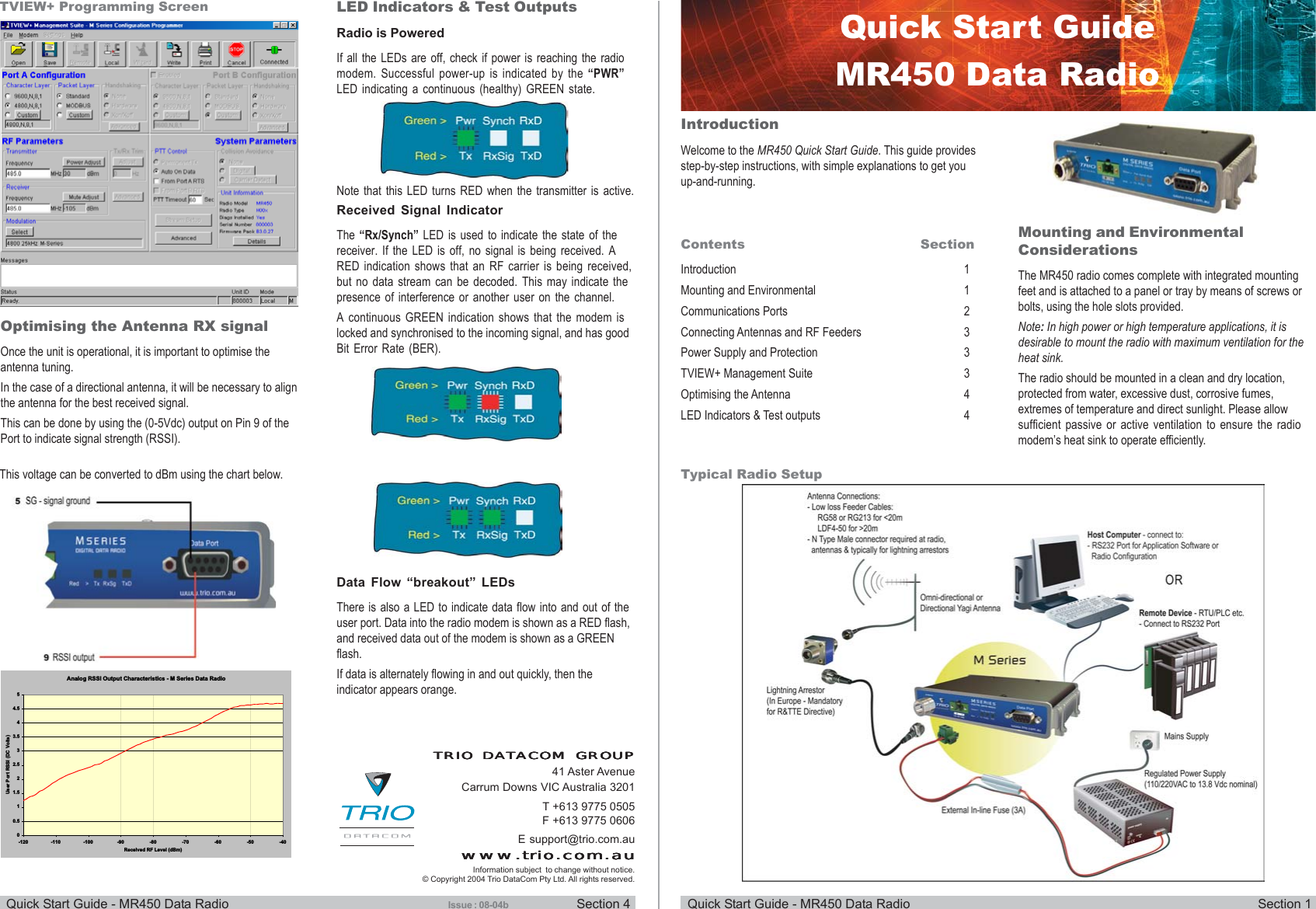
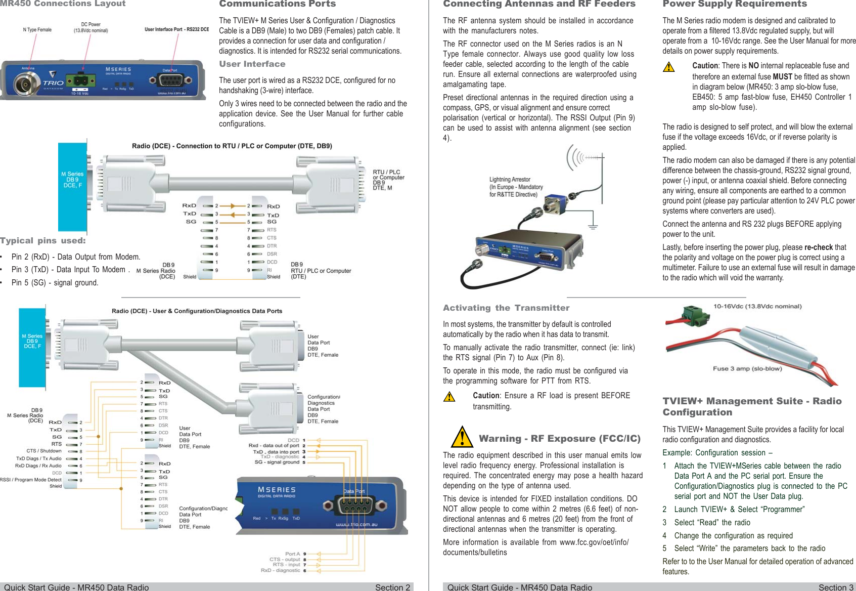
- 2. Quick Start Guide
Quick Start Guide