Schneider Electric Systems Canada MR450-X003 FM Radio Modem User Manual M Series Quick Start Guide
Trio Datacom Pty Ltd (a wholly owned company of Schneider Electric) FM Radio Modem M Series Quick Start Guide
Contents
- 1. User Manual
- 2. Quick Start Guide
Quick Start Guide
Quick Start Guide - MR450 Data Radio Section 1Quick Start Guide - MR450 Data Radio Section 4
Introduction
Welcome to the MR450 Quick Start Guide. This guide provides
step-by-step instructions, with simple explanations to get you
up-and-running.
Contents Section
Introduction 1
Mounting and Environmental 1
Communications Ports 2
Connecting Antennas and RF Feeders 3
Power Supply and Protection 3
TVIEW+ Management Suite 3
Optimising the Antenna 4
LED Indicators & Test outputs 4
Mounting and Environmental
Considerations
The MR450 radio comes complete with integrated mounting
feet and is attached to a panel or tray by means of screws or
bolts, using the hole slots provided.
Note: In high power or high temperature applications, it is
desirable to mount the radio with maximum ventilation for the
heat sink.
The radio should be mounted in a clean and dry location,
protected from water, excessive dust, corrosive fumes,
extremes of temperature and direct sunlight. Please allow
sufficient passive or active ventilation to ensure the radio
modem’s heat sink to operate efficiently.
Quick Start Guide
MR450 Data Radio
Typical Radio Setup
Optimising the Antenna RX signal
Once the unit is operational, it is important to optimise the
antenna tuning.
In the case of a directional antenna, it will be necessary to align
the antenna for the best received signal.
This can be done by using the (0-5Vdc) output on Pin 9 of the
Port to indicate signal strength (RSSI).
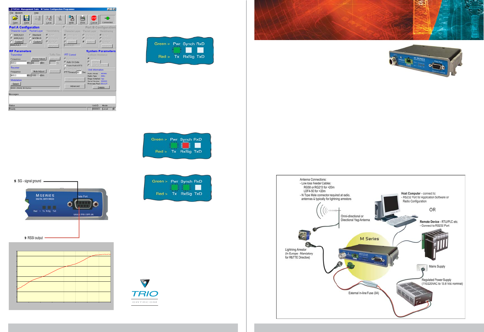
TVIEW+ Programming Screen LED Indicators & Test Outputs
Radio is Powered
If all the LEDs are off, check if power is reaching the radio
modem. Successful power-up is indicated by the “PWR”
LED indicating a continuous (healthy) GREEN state.
Received Signal Indicator
The “Rx/Synch” LED is used to indicate the state of the
receiver. If the LED is off, no signal is being received. A
RED indication shows that an RF carrier is being received,
but no data stream can be decoded. This may indicate the
presence of interference or another user on the channel.
A continuous GREEN indication shows that the modem is
locked and synchronised to the incoming signal, and has good
Bit Error Rate (BER).
Analog RSSI Output Characteristics - M Series Data Radio
0
0.5
1
1.5
2
2.5
3
3.5
4
4.5
5
-120 -110 -100 -90 -80 -70 -60 -50 -40
Received RF Level (dBm)
User Port RSSl (DC Volts)
T +613 9775 0505
F +613 9775 0606
E support@trio.com.au
www.trio.com.auwww.trio.com.au
www.trio.com.auwww.trio.com.au
www.trio.com.au
TRIO DATRIO DA
TRIO DATRIO DA
TRIO DATT
TT
TACOM GROUPACOM GROUP
ACOM GROUPACOM GROUP
ACOM GROUP
41 Aster Avenue
Carrum Downs VIC Australia 3201
Information subject to change without notice.
© Copyright 2004 Trio DataCom Pty Ltd. All rights reserved.
Data Flow “breakout” LEDs
There is also a LED to indicate data flow into and out of the
user port. Data into the radio modem is shown as a RED flash,
and received data out of the modem is shown as a GREEN
flash.
If data is alternately flowing in and out quickly, then the
indicator appears orange.
Issue : 08-04b
This voltage can be converted to dBm using the chart below.
Note that this LED turns RED when the transmitter is active.
Quick Start Guide - MR450 Data Radio Section 2 Quick Start Guide - MR450 Data Radio Section 3
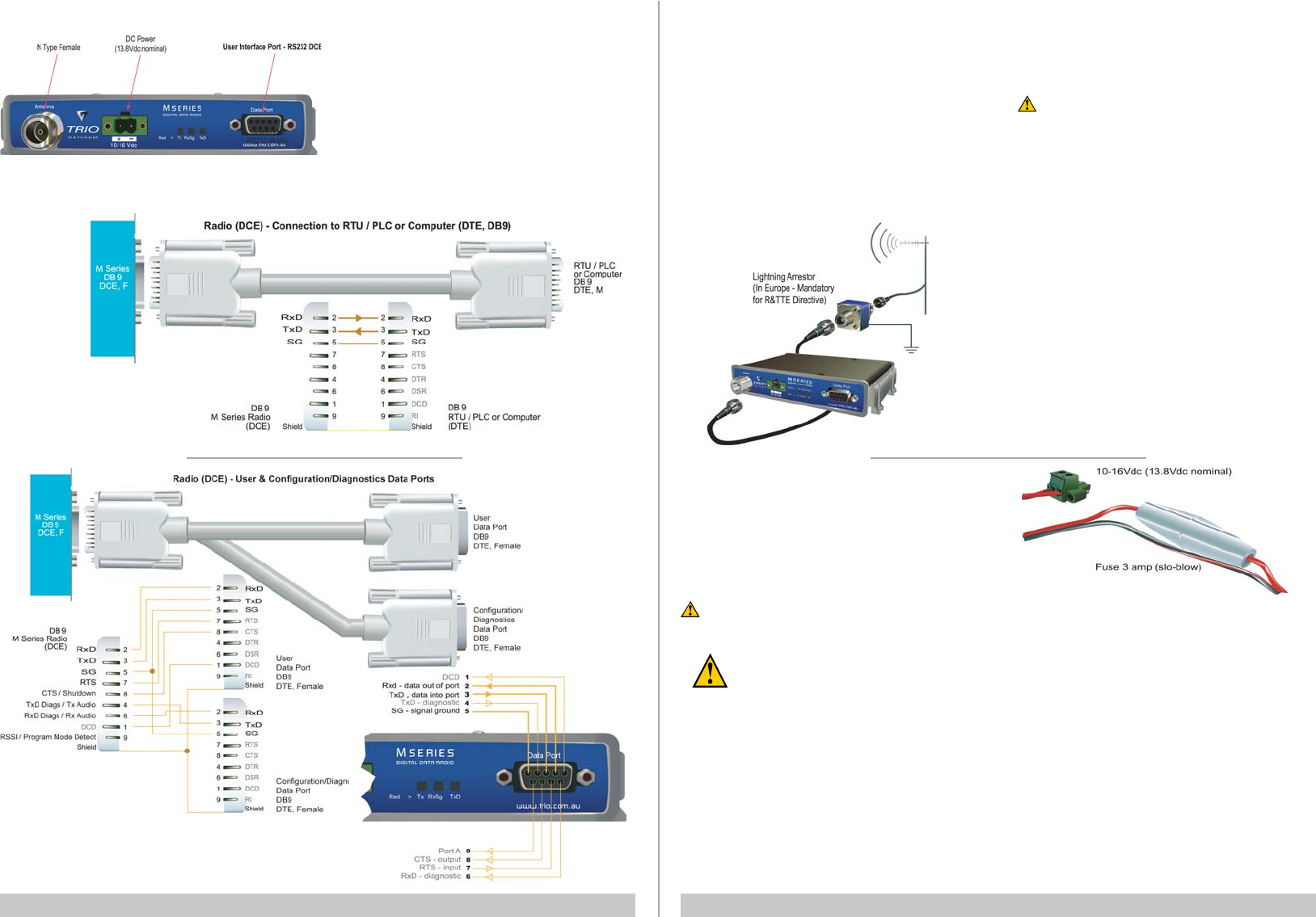
Communications Ports
The TVIEW+ M Series User & Configuration / Diagnostics
Cable is a DB9 (Male) to two DB9 (Females) patch cable. It
provides a connection for user data and configuration /
diagnostics. It is intended for RS232 serial communications.
User Interface
The user port is wired as a RS232 DCE, configured for no
handshaking (3-wire) interface.
Only 3 wires need to be connected between the radio and the
application device. See the User Manual for further cable
configurations.
MR450 Connections Layout
Typical pins used:
• Pin 2 (RxD) - Data Output from Modem.
• Pin 3 (TxD) - Data Input To Modem .
• Pin 5 (SG) - signal ground.
Connecting Antennas and RF Feeders
The RF antenna system should be installed in accordance
with the manufacturers notes.
The RF connector used on the M Series radios is an N
Type female connector. Always use good quality low loss
feeder cable, selected according to the length of the cable
run. Ensure all external connections are waterproofed using
amalgamating tape.
Preset directional antennas in the required direction using a
compass, GPS, or visual alignment and ensure correct
polarisation (vertical or horizontal). The RSSI Output (Pin 9)
can be used to assist with antenna alignment (see section
4).
Activating the Transmitter
In most systems, the transmitter by default is controlled
automatically by the radio when it has data to transmit.
To manually activate the radio transmitter, connect (ie: link)
the RTS signal (Pin 7) to Aux (Pin 8).
To operate in this mode, the radio must be configured via
the programming software for PTT from RTS.
Caution: Ensure a RF load is present BEFORE
transmitting.
Power Supply Requirements
The M Series radio modem is designed and calibrated to
operate from a filtered 13.8Vdc regulated supply, but will
operate from a 10-16Vdc range. See the User Manual for more
details on power supply requirements.
Caution: There is NO internal replaceable fuse and
therefore an external fuse MUST be fitted as shown
in diagram below (MR450: 3 amp slo-blow fuse,
EB450: 5 amp fast-blow fuse, EH450 Controller 1
amp slo-blow fuse).
The radio is designed to self protect, and will blow the external
fuse if the voltage exceeds 16Vdc, or if reverse polarity is
applied.
The radio modem can also be damaged if there is any potential
difference between the chassis-ground, RS232 signal ground,
power (-) input, or antenna coaxial shield. Before connecting
any wiring, ensure all components are earthed to a common
ground point (please pay particular attention to 24V PLC power
systems where converters are used).
Connect the antenna and RS 232 plugs BEFORE applying
power to the unit.
Lastly, before inserting the power plug, please re-check that
the polarity and voltage on the power plug is correct using a
multimeter. Failure to use an external fuse will result in damage
to the radio which will void the warranty.
TVIEW+ Management Suite - Radio
Configuration
This TVIEW+ Management Suite provides a facility for local
radio configuration and diagnostics.
Example: Configuration session –
1 Attach the TVIEW+MSeries cable between the radio
Data Port A and the PC serial port. Ensure the
Configuration/Diagnostics plug is connected to the PC
serial port and NOT the User Data plug.
2 Launch TVIEW+ & Select “Programmer”
3 Select “Read” the radio
4 Change the configuration as required
5 Select “Write” the parameters back to the radio
Refer to to the User Manual for detailed operation of advanced
features.
Warning - RF Exposure (FCC/IC)
The radio equipment described in this user manual emits low
level radio frequency energy. Professional installation is
required. The concentrated energy may pose a health hazard
depending on the type of antenna used.
This device is intended for FIXED installation conditions. DO
NOT allow people to come within 2 metres (6.6 feet) of non-
directional antennas and 6 metres (20 feet) from the front of
directional antennas when the transmitter is operating.
More information is available from www.fcc.gov/oet/info/
documents/bulletins