Schneider Electric Systems Canada OM240 2.4GHz frequency hopping spread spectrum rf module User Manual O Series 08 08 indd
Trio Datacom Pty Ltd (a wholly owned company of Schneider Electric) 2.4GHz frequency hopping spread spectrum rf module O Series 08 08 indd
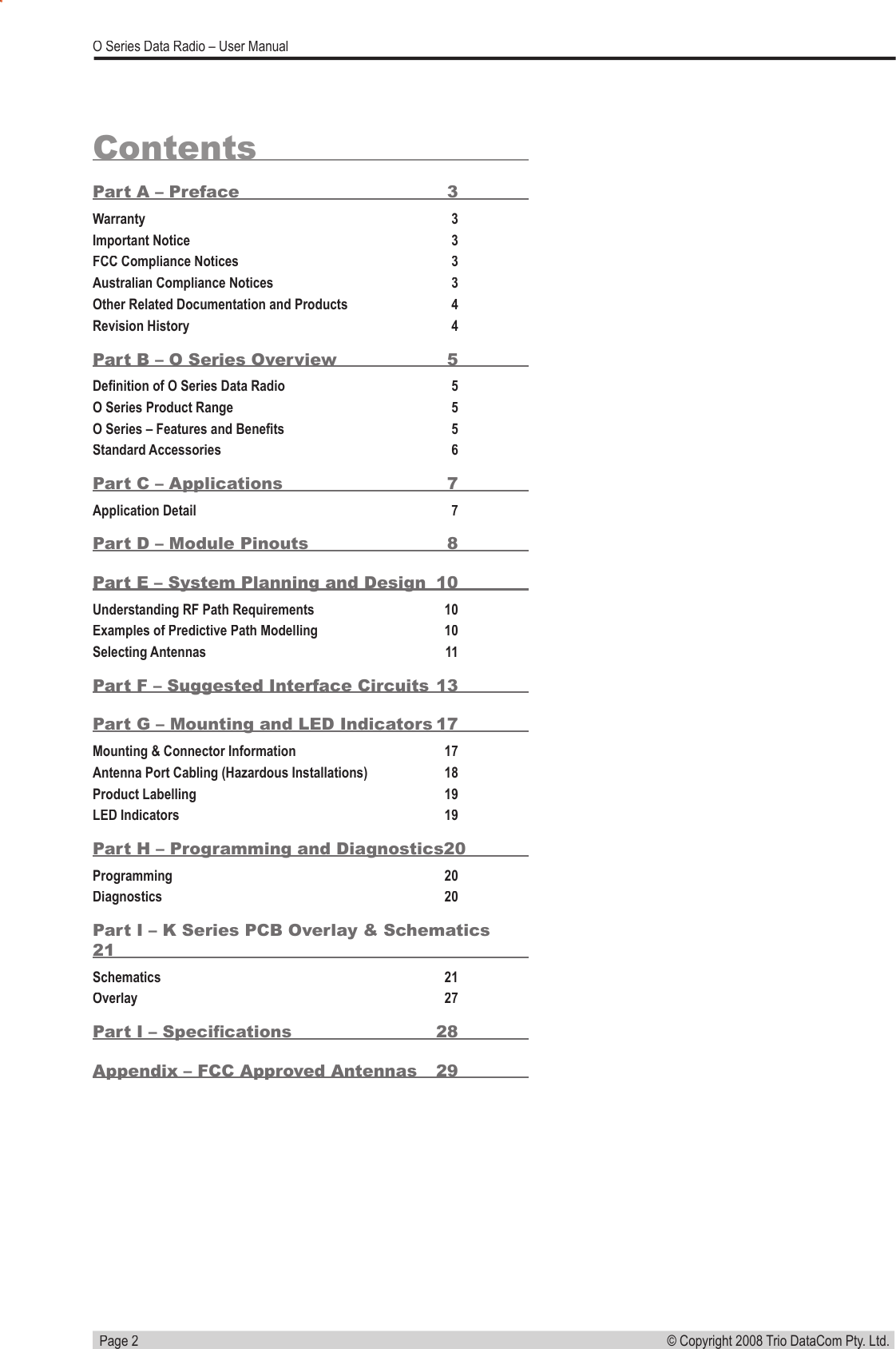
Contents
- 1. Users Manual 1
- 2. Users Manual 2
Users Manual 1

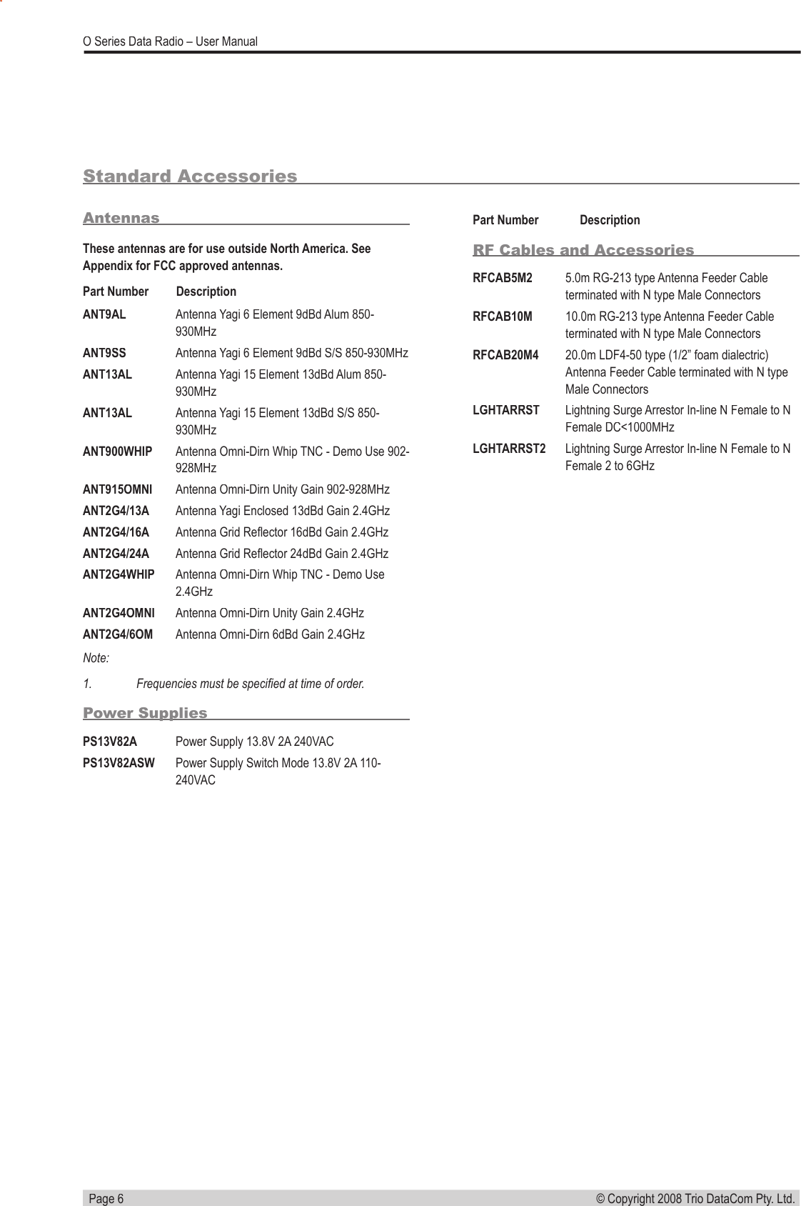
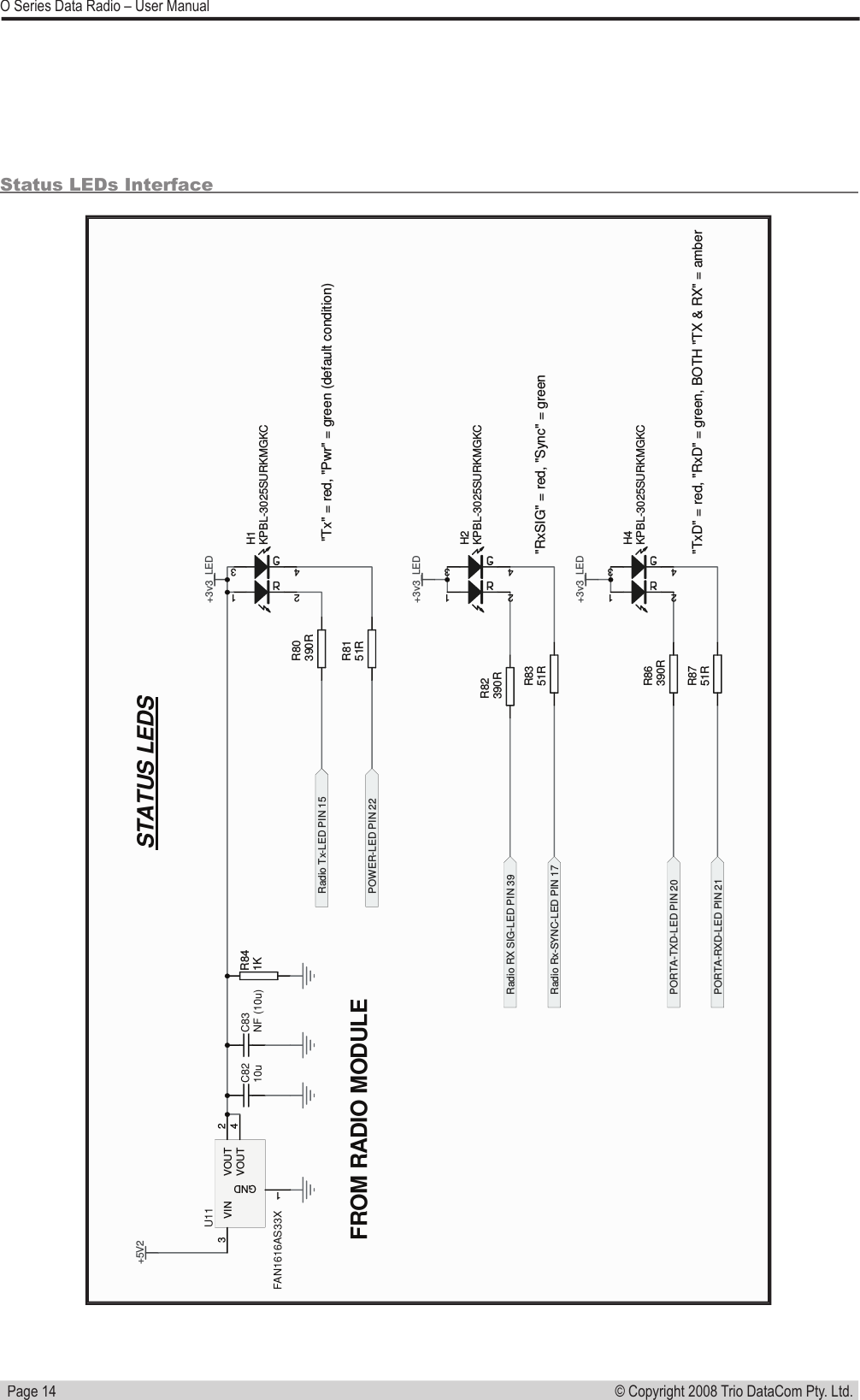
![Page 8© Copyright 2008 Trio DataCom Pty. Ltd. O Series Data Radio – User ManualPart D – Module PinoutsRecommended ConnectionsPower SupplyPinNameIn/OutCommentLevel6VCCI3.3V Supply Input 100mA+/-5%10PAVCCIPA Supply Input 5V+/-5%11GNDN/A12PAVCCIPA Supply Input 5V+/-5%14GNDN/APort A (aka Port 2)1PORT2-TxDIInput for transmit for Port 2 [Port A on K-Series]3.3V TTL2PORT2-RxDOOutput for received data for Port 2 [Port A on K-Series]3.3V TTLPort B (aka Port 1)29PORT1-TxDIInput for transmit for Port 1 [Port B on K-Series]3.3V TTL30PORT1-RxDOOutput for received data for Port 1 [Port B on K-Series]3.3V TTLSystems Port7SysSerInIDiagnostics/FDL input data or Testmode command 3.3V TTL8SysSerOutODiagnostics/FDL output or Testmode command3.3V TTLLEDs15Tx_LEDOTx activity (Active Low)3.3V TTL17Sync_LEDOMasters: 100ms pulse when user data received (Active Low)Remotes/Bridges: pulsed every 1500ms for 100ms when master acquired, additional 100ms pulse when user data received (Active Low)3.3V TTL18TxD_PORT1_LEDOPulsed for 100ms for any TxD activity for Port 1 [Port B on K-Series] (Active Low) 3.3V TTL19RxD_PORT1_LEDOPulsed for 100ms for any RxD activity for Port 1 [Port B on K-Series] (Active Low)3.3V TTL20TxD_PORT2_LEDOPulsed for 100ms for any TxD activity for Port 2 [Port A on K-Series] (Active Low) 3.3V TTL21RxD_PORT2_LEDOPulsed for 100ms for any RxD activity Port 2 [Port A on K-Series] (Active Low)3.3V TTL22Pwr_LEDODC power OK (Active Low)3.3V TTL39NoSIG_LEDOMasters: not activityRemotes/Bridges: pulsed every 1500ms for 100ms when master not ac-quired (Active Low)3.3V TTL](https://usermanual.wiki/Schneider-Electric-Systems-Canada/OM240.Users-Manual-1/User-Guide-996837-Page-8.png)
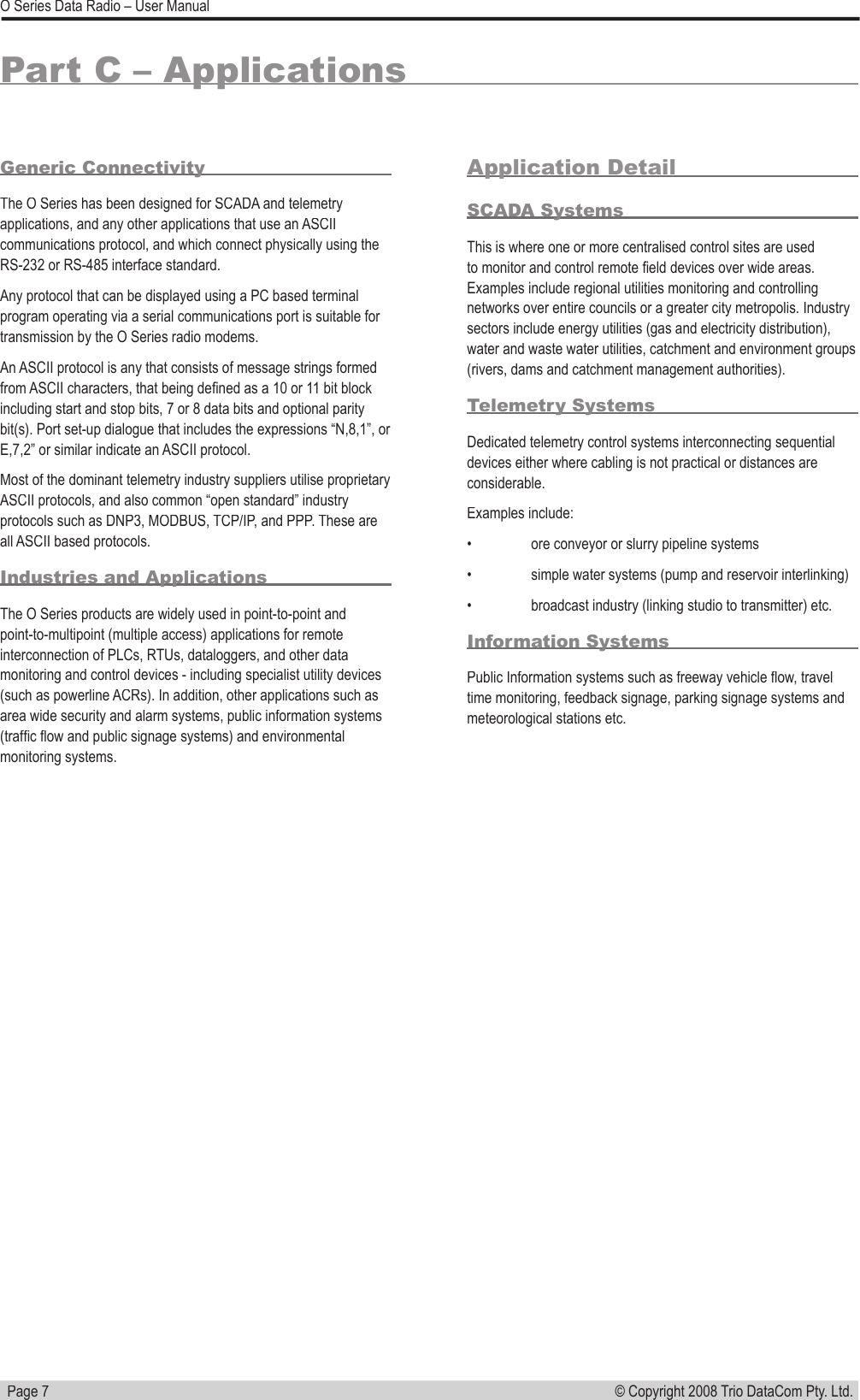
![Page 9© Copyright 2008 Trio DataCom Pty. Ltd. O Series Data Radio – User ManualOther Pins13Analogue RSSIOSynthesised average of RSSI (20dB/V absolute reference : -90dBm = 1.25v)[can also be used as a general purpose analogue output]0-2.5v24PTTIKeys the radio at maximum TX/RX duty cycle using the current programmed channel selection and output power (Active Low).Note that while a radio is in this mode no data can be passed, the RSSI indication on other units will not respond to the radio being PTT keyed and it may block other systems.3.3V TTLOptional ConnectionsPort A (aka Port 2)3PORT2-CTSOFlow control of TxD for Port 2 [Port A on K-Series]3.3V TTL4PORT2-RTSIFlow control of TxD for Port 2 [Port A on K-Series]3.3V TTL5PORT2-DTRIFlow control of RxD for Port 2 [Port A on K-Series]3.3V TTL9PORT2-DCDOFlow control of RxD for Port A3.3V TTLPort B (aka Port 1)31PORT1-RTSIFlow control of TxD for Port 1 [Port B on K-Series]3.3V TTL32PORT1-CTSOFlow control of TxD for Port 1 [Port B on K-Series]3.3V TTL33PORT1-DTRIFlow control of RxD for Primary Data Port [Port B on K-Series]3.3V TTL34PORT1-DCDOFlow control of RxD for Port 1 [Port B on K-Series]3.3V TTLOther connections (Optional)PinNameIn/OutCommentLevel16Analogue InputIGeneral purpose analogue input. 66k input resistance.0-6v23nFACT/TEST-MODEIReset factory defaults (Active Low on power-up)3.3V TTL25TxInhibitITx inhibit for hot standby operation (Active High)3.3V TTL26nSHUTDOWN_INIPower down entire module (Active Low)3.3V TTL27TxSync InputITx Sync input3.3V TTL28TxSync OutputOTx Sync output3.3V TTL35TWDION/C - Factory Use Only3.3V TTL36TWCKON/C - Factory Use Only3.3V TTL37SUPPLY_MONI-TORIN/C - Factory Use Only0-3V, Hi-Z38SHUTDOWN_OUTON/C - Factory Use Only3.3V TTL40NVRAM-WPON/C - Factory Use Only3.3V TTL](https://usermanual.wiki/Schneider-Electric-Systems-Canada/OM240.Users-Manual-1/User-Guide-996837-Page-9.png)