Schneider Electric Systems Canada OM240 2.4GHz frequency hopping spread spectrum rf module User Manual O Series 08 08 indd
Trio Datacom Pty Ltd (a wholly owned company of Schneider Electric) 2.4GHz frequency hopping spread spectrum rf module O Series 08 08 indd
Contents
- 1. Users Manual 1
- 2. Users Manual 2
Users Manual 1

O Series
User Manual

Page 2
© Copyright 2008 Trio DataCom Pty. Ltd.
O Series Data Radio – User Manual
Contents
Part A – Preface 3
Warranty
3
Important Notice
3
FCC Compliance Notices
3
Australian
Compliance Notices
3
Other Related Documentation and Products
4
Revision History
4
Part B – O Series Overview 5
Defi nition of O Series Data Radio
5
O Series Product Range
5
O
Series – Features and Benefi ts
5
Standard Accessories
6
Part C – Applications 7
Application Detail
7
Part D – Module Pinouts 8
Part E – System Planning and Design 10
Understanding RF Path Requirements 1
0
Examples of Predictive Path Modelling 1
0
Selecting Antennas 1
1
Part F – Suggested Interface Circuits 13
Part G – Mounting and LED Indicators 17
Mounting & Connector Information 1
7
Antenna Port Cabling (Hazardous
Installations) 1
8
Product Labelling 1
9
LED Indicators 1
9
Part H – Programming and Diagnostics 20
Programming 2
0
Diagnostics 2
0
Part I – K Series PCB Overlay & Schematics
21
Schematics 2
1
Overlay 2
7
Part I – Specifi cations 28
Appendix – FCC Approved Antennas 29
Page 3
© Copyright 2008 Trio DataCom Pty. Ltd.
O Series Data Radio – User Manual
Warranty
All equipment supplied by Trio DataCom Pty Ltd is covered by
warranty for faulty workmanship and parts for a period of twelve
(12) months from the date of delivery to the customer. During the
warranty period Trio DataCom Pty Ltd shall, at its option, repair
or replace faulty parts or equipment provided the fault has not
been caused by misuse, accident, deliberate damage, abnormal
atmosphere, liquid immersion or lightning discharge; or where
attempts have been made by unauthorised persons to repair or
modify the equipment.
The warranty does not cover modifi cations to software. All
equipment for repair under warranty must be returned freight paid
to Trio DataCom Pty Ltd or to such other place as Trio DataCom
Pty Ltd shall nominate. Following repair or replacement the
equipment shall be returned to the customer freight forward. If it is
not possible due to the nature of the equipment for it to be returned
to Trio DataCom Pty Ltd, then such expenses as may be incurred
by Trio DataCom Pty Ltd in servicing the equipment in situ shall be
chargeable to the customer.
When equipment for repair does not qualify for repair or
replacement under warranty, repairs shall be performed at the
prevailing costs for parts and labour. Under no circumstances shall
Trio DataCom Pty Ltd’s liability extend beyond the above nor shall
Trio DataCom Pty Ltd, its principals, servants or agents be liable
for the consequential damages caused by the failure or malfunction
of any equipment.
Important Notice
© Copyright 2007 Trio DataCom Pty Ltd All Rights Reserved
This manual covers the operation of the M Series of Digital Data
Radios. Specifi cations described are typical only and are subject to
normal manufacturing and service tolerances.
Trio DataCom Pty Ltd reserves the right to modify the equipment,
its specifi cation or this manual without prior notice, in the interest
of improving performance, reliability or servicing. At the time of
publication all data is correct for the operation of the equipment
at the voltage and/or temperature referred to. Performance data
indicates typical values related to the particular product.
This manual is copyright by Trio DataCom Pty Ltd. All rights
reserved. No part of the documentation or the information supplied
may be divulged to any third party without the express written
permission of Trio DataCom Pty Ltd.
Same are proprietary to Trio DataCom Pty Ltd and are supplied
for the purposes referred to in the accompanying documentation
and must not be used for any other purpose. All such information
remains the property of Trio DataCom Pty Ltd and may not be
reproduced, copied, stored on or transferred to any other media or
used or distributed in any way save for the express purposes for
which it is supplied.
Products offered may contain software which is proprietary to Trio
DataCom Pty Ltd. However, the offer of supply of these products
and services does not include or infer any transfer of ownership
of such proprietary information and as such reproduction or reuse
without the express permission in writing from Trio DataCom Pty
Ltd is forbidden. Permission may be applied for by contacting Trio
DataCom Pty Ltd in writing.
Part A – Preface
FCC Compliance Notices
FCC Part 15 Notice
This device complies with Part 15 of the FCC Rules. Operation
is subject to the following two conditions: (1) this device may
not cause harmful interference, and (2) this device must accept
any interference received including interference that may cause
undesired operation.
This device must not be modifi ed in any way or FCC compliance
may be void.
FCC Approved Antennas
This device can only be used with Antennas listed in the Appendix
of the O Series User Manual. Please Contact Trio Datacom if you
need more information or would like to order an antenna.
RF Exposure
To satisfy FCC RF exposure requirements for mobile transmitting
devices, a separation distance of 20
cm or more should be
maintained between the antenna of this device and persons during
device operation. To ensure compliance, operations at closer
than this distance is not recommended. The antenna used for this
transmitter must not be co-located in conjunction with any other
antenna or transmitter.
MAXIMUM EIRP
FCC Regulations allow up to 36 dBm effective isotropic radiated
power (EIRP). Therefore, the
sum of the transmitted power (in
dBm), the cabling loss and the antenna gain (in dBi) cannot exceed
36 dBm.
FCC Point to Point : More EIRP may be allowed for fi xed point to
point links. With the transmitter set to 27dBm, an antenna gain
(subtracting cable loss) of up to 15 dBi is allowed. For antenna
gains of more than 15 dBi in a fi xed point to point link, the power
must be backed off from 27dBm by 1dB for every 3dB the antenna
gain exceeds 15dBi.
ETSI Maximum EIRP for the 2.4GHz band is +20dBm.
Australian Compliance Notices
MAXIMUM EIRP
ACMA Regulations allow up to 30 dBm (1 Watt) of effective
isotropic radiated power (EIRP) in the 915MHz license free band
and 36 dBm (4 Watts) of EIRP in the 2.4GHz band. Therefore, the
sum of the transmitted power (in dBm), the cabling loss and the
antenna gain cannot exceed the above stated EIRP limits.

Page 4
© Copyright 2008 Trio DataCom Pty. Ltd.
O Series Data Radio – User Manual
Other Related Documentation
and Products
Revision History
Issue 1 May 2007 Initial Release
Issue 2 Jun 2007 Minor FCC Modifi cations
Issue 3 Jul 2007 Minor FCC Modifi cations
Issue 4 Oct 2007 Hazardous Notices
Issue 5 Nov 2007 Updated product specifi cations.
Issue 6 Aug 2008 Added 2.4GHz
WEEE Notice (Europe)
This symbol on the product or its packaging indicates that this
product must not be disposed of with other waste. Instead, it is
your responsibility to dispose of your waste equipment by handing
it over to a designated collection point for the recycling of waste
electrical and electronic equipment. The separate collection and
recycling of your waste equipment at the time of disposal will help
conserve natural resources and ensure that it is recycled in a
manner that protects human health and the environment. For more
information about where you can drop off your waste equipment
for recycling, please contact the dealer from whom you originally
purchased the product.
Dieses Symbol auf dem Produkt oder seinem Verpacken
zeigt an, daß dieses Produkt nicht mit anderer Vergeudung
entledigt werden darf. Stattdessen ist es Ihre Verantwortlichkeit,
sich Ihre überschüssige Ausrüstung zu entledigen, indem es
rüber sie zu einem gekennzeichneten Ansammlungspunkt
für die Abfallverwertung elektrische und elektronische
Ausrüstung übergibt. Die unterschiedliche Ansammlung und
die Wiederverwertung Ihrer überschüssigen Ausrüstung zu der
Zeit der Beseitigung helfen, Naturresourcen zu konservieren
und sicherzugehen, daß es in gewissem Sinne aufbereitet wird,
daß menschliche Gesundheit und das Klima schützt. Zu mehr
Information ungefähr, wo Sie weg von Ihrer überschüssigen
Ausrüstung für die Wiederverwertung fallen können, treten Sie
bitte mit dem Händler in Verbindung, von dem Sie ursprünglich das
Produkt kauften.
Low Voltage Safety (Europe)
In order to comply with the R&TTE (Radio & Telecommunications
Terminal Equipment) directive 1999/5/EC Article 3 (Low Voltage
Directive 73/23/EEC), all radio modem installations must include an
external in-line lightning arrestor or equivalent device that complies
with the following specifi cations:
• DC Blocking Capability - 1.5kV impulse (Rise Time 10mS,
Fall Time 700mS) (Repetition 10 Times) or 1.0kV rms 50Hz
sine wave for 1 minute.
The OM240 has been classifi ed as SELV throughout. All ports
shall be connected to like circuits and shall not extend beyond the
building boundary of the host equipment unless connected via
an isolation unit compliant with the requirements of section 7 of
EN60950-1.
Important Notices for Class I, Division 2,
Groups A, B, C & D Hazardous Locations
Applies to models OM900-xxxxx-x
Applies to models OM900-xxxxx-x
H
x(CSA Marked)
This product is available for use in Class I, Division 2, Groups
A, B, C & D Hazardous Locations. Such locations are defi ned in
Article 500 of the US National Fire Protection Association (NFPA)
publication NFPA 70, otherwise known as the National Electrical
Code and in Section 18 of the Canadian Standards Association
C22.1 (Canadian Electrical Code).
The transceiver has been recognised for use in these hazardous
locations by the Canadian Standards Association (CSA)
International. CSA certifi cation is in accordance with CSA Standard
C22.2 No. 213-M1987 and UL Standard 1604 subject to the
following conditions of approval:
1. This Equipment is suitable for use in class I, division 2, Groups
A,B,C and D or non Hazardous locations only.
2. This module is certifi ed as “Open type” equipment and must be
used in a suitable end use enclosure.
3. The antenna, DC power and interface cables must be routed
through conduit in accordance with the National Electrical Codes.
4. Installation, operation and maintenance of the radio modem
should be in accordance with the radio modem’s user manual and
the National Electrical Codes.
5. Tampering or replacement with non-factory components may
adversely affect the safe use of the radio modem in hazardous
locations and may void the approval.
6. Power supplied to this equipment must be from a CLASS 2
source (per National Electrical Code, NFPA 70, Article 725.41, and
Canadian Electrical Code, C22.1, rule 16-200) or otherwise limited
to the voltage levels specifi ed for this equipment, with available
current of < 5A.
7. The antenna connectors used must be secured to the module by
using one of the two methods shown in this manual.
WARNING EXPLOSION HAZARD
DO NOT DISCONNECT EQUIPMENT UNLESS POWER HAS
BEEN TURNED OFF OR THE AREA IS KNOWN TO BE NON-
HAZARDOUS.
Electrical Ratings
5 volts @ 1.2A
3.3 volts @ 300mA
Environmental Ratings
Operating Temperature: -40 to +75 degC
Temperature code: T4

Page 5
© Copyright 2008 Trio DataCom Pty. Ltd.
O Series Data Radio – User Manual
Part B – O Series Overview
Defi nition of O Series Data Radio
Trio O Series industrial strength spread spectrum data radios are
the ideal solution for professional serial data communications in
wireless point to point or point to multi-point SCADA and telemetry
applications when the use of licensed frequencies is not possible
or when data throughput requirements are greater than traditional
licensed frequency equipment can achieve.
O Series systems can be rapidly deployed as permanent or
temporary alternatives to costly cable based circuits. They allow
complex networks with extended coverage to be implemented at
minimum cost, delivering dependable communications in the most
demanding environments.
O Series Product Range
The TRIO O Series comprises the OM900, which operates within
the 902-928MHz license free frequency band, and the OM240
that can be confi gured for use in the 2.4GHz license free bands
available throughout the world.
O Series – Features and Benefi ts
Radio
• License free communication in international 2.4GHz and
902-928 MHz ISM frequency bands
• Versions suitable for use in most parts of the world
• Robust, frequency hopping spread spectrum technology for
superior interference immunity
• 900MHz - 1 Watt transmitter output power
• 2.4GHz - 500 mWatt transmitter output power
• High performance receiver
• 256kbps over the air data speed
• Supports point to point and point to multi-point operation
• User selectable master, remote and repeater operation
• Collision avoidance for simultaneous polling and
spontaneous reporting
Data Modem
• Suitable for most industry standard data protocols e.g.,
MODBUS, DNP3, IEC870-5-101, DF1, etc.
• User confi gurable 1200-115,000 bps asynch RS-232/RS485
port
• Fully transparent 3 wire user interface
• Intelligent transmitter control
• Excellent BER performance
• Internal CRC and user-selectable forward error correction
• Multiple user confi gurable security layers including data
encryption

Page 6
© Copyright 2008 Trio DataCom Pty. Ltd.
O Series Data Radio – User Manual
Antennas
These antennas are for use outside North America. See
Appendix for FCC approved antennas.
Part Number Description
ANT9AL
Antenna Yagi 6 Element 9dBd Alum 850-
930MHz
ANT9SS
Antenna Yagi 6 Element 9dBd S/S 850-930MHz
ANT13AL
Antenna Yagi 15 Element 13dBd Alum 850-
930MHz
ANT13AL
Antenna Yagi 15 Element 13dBd S/S 850-
930MHz
ANT900WHIP
Antenna Omni-Dirn Whip TNC - Demo Use 902-
928MHz
ANT915OMNI
Antenna Omni-Dirn Unity Gain 902-928MHz
ANT2G4/13A
Antenna Yagi Enclosed 13dBd Gain 2.4GHz
ANT2G4/16A
Antenna Grid Refl ector 16dBd Gain 2.4GHz
ANT2G4/24A
Antenna Grid Refl ector 24dBd Gain 2.4GHz
ANT2G4WHIP
Antenna Omni-Dirn Whip TNC - Demo Use
2.4GHz
ANT2G4OMNI
Antenna Omni-Dirn Unity Gain 2.4GHz
ANT2G4/6OM
Antenna Omni-Dirn 6dBd Gain 2.4GHz
Note:
1. Frequencies must be specifi ed at time of order.
Power Supplies
PS13V82A
Power Supply 13.8V 2A 240VAC
PS13V82ASW
Power Supply Switch Mode 13.8V 2A 110-
240VAC
Standard Accessories
Part Number Description
RF Cables and Accessories
RFCAB5M2
5.0m RG-213 type Antenna Feeder Cable
terminated with N type Male Connectors
RFCAB10M
10.0m RG-213 type Antenna Feeder Cable
terminated with N type Male Connectors
RFCAB20M4
20.0m LDF4-50 type (1/2” foam dialectric)
Antenna Feeder Cable terminated with N type
Male Connectors
LGHTARRST
Lightning Surge Arrestor In-line N Female to N
Female DC<1000MHz
LGHTARRST2
Lightning Surge Arrestor In-line N Female to N
Female 2 to 6GHz

Page 7
© Copyright 2008 Trio DataCom Pty. Ltd.
O Series Data Radio – User Manual
Part C – Applications
Generic Connectivity
The O Series has been designed for SCADA and telemetry
applications, and any other applications that use an ASCII
communications protocol, and which connect physically using the
RS-232 or RS-485 interface standard.
Any protocol that can be displayed using a PC based terminal
program operating via a serial communications port is suitable for
transmission by the O Series radio modems.
An ASCII protocol is any that consists of message strings formed
from ASCII characters, that being defi ned as a 10 or 11 bit block
including start and stop bits, 7 or 8 data bits and optional parity
bit(s). Port set-up dialogue that includes the expressions “N,8,1”, or
E,7,2” or similar indicate an ASCII protocol.
Most of the dominant telemetry industry suppliers utilise proprietary
ASCII protocols, and also common “open standard” industry
protocols such as DNP3, MODBUS, TCP/IP, and PPP. These are
all ASCII based protocols.
Industries and Applications
The O Series products are widely used in point-to-point and
point-to-multipoint (multiple access) applications for remote
interconnection of PLCs, RTUs, dataloggers, and other data
monitoring and control devices - including specialist utility devices
(such as powerline ACRs). In addition, other applications such as
area wide security and alarm systems, public information systems
(traffi c fl ow and public signage systems) and environmental
monitoring systems.
Application Detail
SCADA Systems
This is where one or more centralised control sites are used
to monitor and control remote fi eld devices over wide areas.
Examples include regional utilities monitoring and controlling
networks over entire councils or a greater city metropolis. Industry
sectors include energy utilities (gas and electricity distribution),
water and waste water utilities, catchment and environment groups
(rivers, dams and catchment management authorities).
Telemetry Systems
Dedicated telemetry control systems interconnecting sequential
devices either where cabling is not practical or distances are
considerable.
Examples include:
• ore conveyor or slurry pipeline systems
• simple water systems (pump and reservoir interlinking)
• broadcast industry (linking studio to transmitter) etc.
Information Systems
Public Information systems such as freeway vehicle fl ow, travel
time monitoring, feedback signage, parking signage systems and
meteorological stations etc.
Page 8
© Copyright 2008 Trio DataCom Pty. Ltd.
O Series Data Radio – User Manual
Part D – Module Pinouts
Recommended Connections
Power Supply
Pin
Name
In/Out
Comment
Level
6
VCC
I
3.3V Supply Input 100mA
+/-5%
10
PAVCC
I
PA Supply Input 5V
+/-5%
11
GND
N/A
12
PAVCC
I
PA Supply Input 5V
+/-5%
14
GND
N/A
Port A (aka Port 2)
1
PORT2-TxD
I
Input for transmit for Port 2 [Port A on K-Series]
3.3V TTL
2
PORT2-RxD
O
Output for received data for Port 2 [Port A on K-Series]
3.3V TTL
Port B (aka Port 1)
29
PORT1-TxD
I
Input for transmit for Port 1 [Port B on K-Series]
3.3V TTL
30
PORT1-RxD
O
Output for received data for Port 1 [Port B on K-Series]
3.3V TTL
Systems Port
7
SysSerIn
I
Diagnostics/FDL input data or Testmode command
3.3V TTL
8
SysSerOut
O
Diagnostics/FDL output or Testmode command
3.3V TTL
LEDs
15
Tx_LED
O
Tx activity (Active Low)
3.3V TTL
17
Sync_LED
O
Masters: 100ms pulse when user data received (Active Low)
Remotes/Bridges: pulsed every 1500ms for 100ms when master acquired,
additional 100ms pulse when user data received (Active Low)
3.3V TTL
18
TxD_PORT1_LED
O
Pulsed for 100ms for any TxD activity for Port 1 [Port B on K-Series] (Active
Low)
3.3V TTL
19
RxD_PORT1_LED
O
Pulsed for 100ms for any RxD activity for Port 1 [Port B on K-Series] (Active
Low)
3.3V TTL
20
TxD_PORT2_LED
O
Pulsed for 100ms for any TxD activity for Port 2 [Port A on K-Series] (Active
Low)
3.3V TTL
21
RxD_PORT2_LED
O
Pulsed for 100ms for any RxD activity Port 2 [Port A on K-Series] (Active
Low)
3.3V TTL
22
Pwr_LED
O
DC power OK (Active Low)
3.3V TTL
39
NoSIG_LED
O
Masters: not activity
Remotes/Bridges: pulsed every 1500ms for 100ms when master not ac-
quired (Active Low)
3.3V TTL
Page 9
© Copyright 2008 Trio DataCom Pty. Ltd.
O Series Data Radio – User Manual
Other Pins
13
Analogue RSSI
O
Synthesised average of RSSI (20dB/V absolute reference : -90dBm = 1.25v)
[can also be used as a general purpose analogue output]
0-2.5v
24
PTT
I
Keys the radio at maximum TX/RX duty cycle using the current programmed
channel selection and output power (Active Low).
Note that while a radio is in this mode no data can be passed, the RSSI
indication on other units will not respond to the radio being PTT keyed and it
may block other systems.
3.3V TTL
Optional Connections
Port A (aka Port 2)
3
PORT2-CTS
O
Flow control of TxD for Port 2 [Port A on K-Series]
3.3V TTL
4
PORT2-RTS
I
Flow control of TxD for Port 2 [Port A on K-Series]
3.3V TTL
5
PORT2-DTR
I
Flow control of RxD for Port 2 [Port A on K-Series]
3.3V TTL
9
PORT2-DCD
O
Flow control of RxD for Port A
3.3V TTL
Port B (aka Port 1)
31
PORT1-RTS
I
Flow control of TxD for Port 1 [Port B on K-Series]
3.3V TTL
32
PORT1-CTS
O
Flow control of TxD for Port 1 [Port B on K-Series]
3.3V TTL
33
PORT1-DTR
I
Flow control of RxD for Primary Data Port [Port B on K-Series]
3.3V TTL
34
PORT1-DCD
O
Flow control of RxD for Port 1 [Port B on K-Series]
3.3V TTL
Other connections (Optional)
Pin
Name
In/Out
Comment
Level
16
Analogue Input
I
General purpose analogue input. 66k input resistance.
0-6v
23
nFACT/TEST-
MODE
I
Reset factory defaults (Active Low on power-up)
3.3V TTL
25
TxInhibit
I
Tx inhibit for hot standby operation (Active High)
3.3V TTL
26
nSHUTDOWN_IN
I
Power down entire module (Active Low)
3.3V TTL
27
TxSync Input
I
Tx Sync input
3.3V TTL
28
TxSync Output
O
Tx Sync output
3.3V TTL
35
TWD
IO
N/C - Factory Use Only
3.3V TTL
36
TWCK
O
N/C - Factory Use Only
3.3V TTL
37
SUPPLY_MONI-
TOR
I
N/C - Factory Use Only
0-3V,
Hi-Z
38
SHUTDOWN_
OUT
O
N/C - Factory Use Only
3.3V TTL
40
NVRAM-WP
O
N/C - Factory Use Only
3.3V TTL
Page 10
© Copyright 2008 Trio DataCom Pty. Ltd.
O Series Data Radio – User Manual
Part E – System Planning and Design
Understanding RF Path
Requirements
A radio modem needs a minimum amount of received RF signal to
operate reliably and provide adequate data throughput.
In most cases, spectrum regulatory authorities will also defi ne
or limit the amount of signal that can be transmitted, and the
transmitted power will decay with distance and other factors, as it
moves away from the transmitting antenna.
It follows, therefore, that for a given transmission level, there will
be a fi nite distance at which a receiver can operate reliably with
respect to the transmitter.
Apart from signal loss due to distance, other factors that will decay
a signal include obstructions (hills, buildings, foliage), horizon
(effectively the bulge between two points on the earth), and factors
such as fog, heavy rain-bursts, dust storms, etc.
In order to ascertain the available RF coverage from a transmitting
station, it will be necessary to consider these factors. This can be
done in a number of ways, including
(a) using basic formulas to calculate the theoretically available
signal - allowing only for free space loss due to distance,
(b) using sophisticated software to build earth terrain models
and apply other correction factors such as earth curvature
and the effects of obstructions, and
(c) by actual fi eld strength testing.
It is good design practice to consider the results of at least two of
these models to design a radio path.
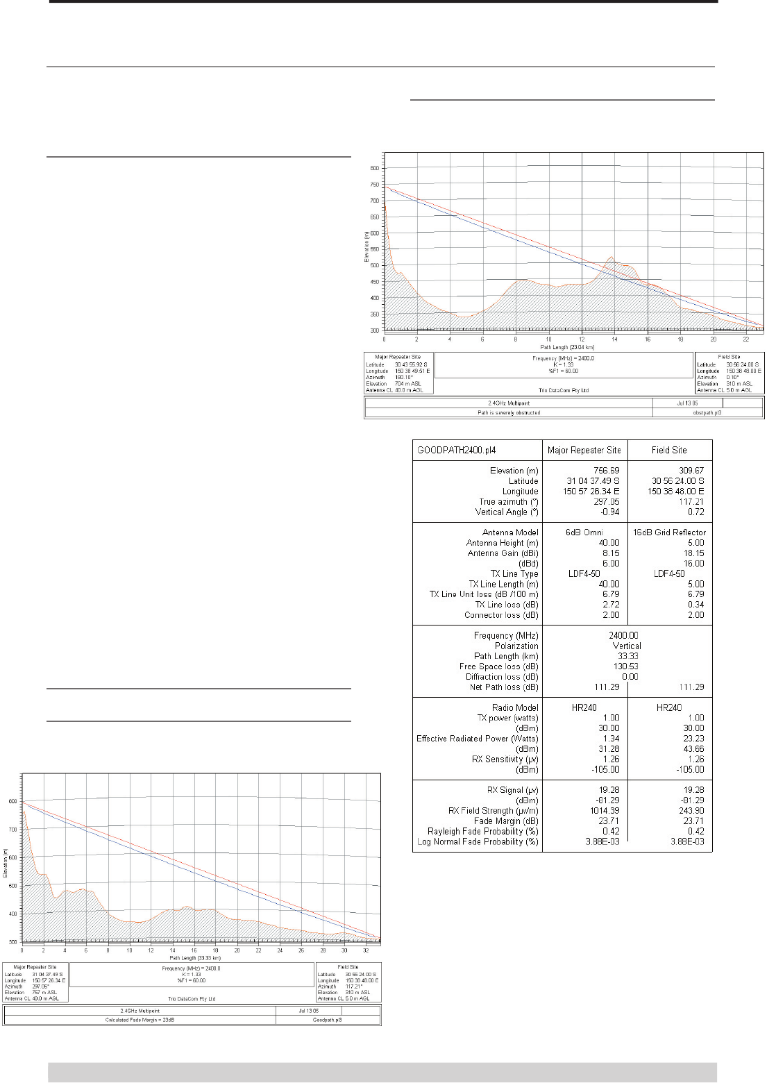
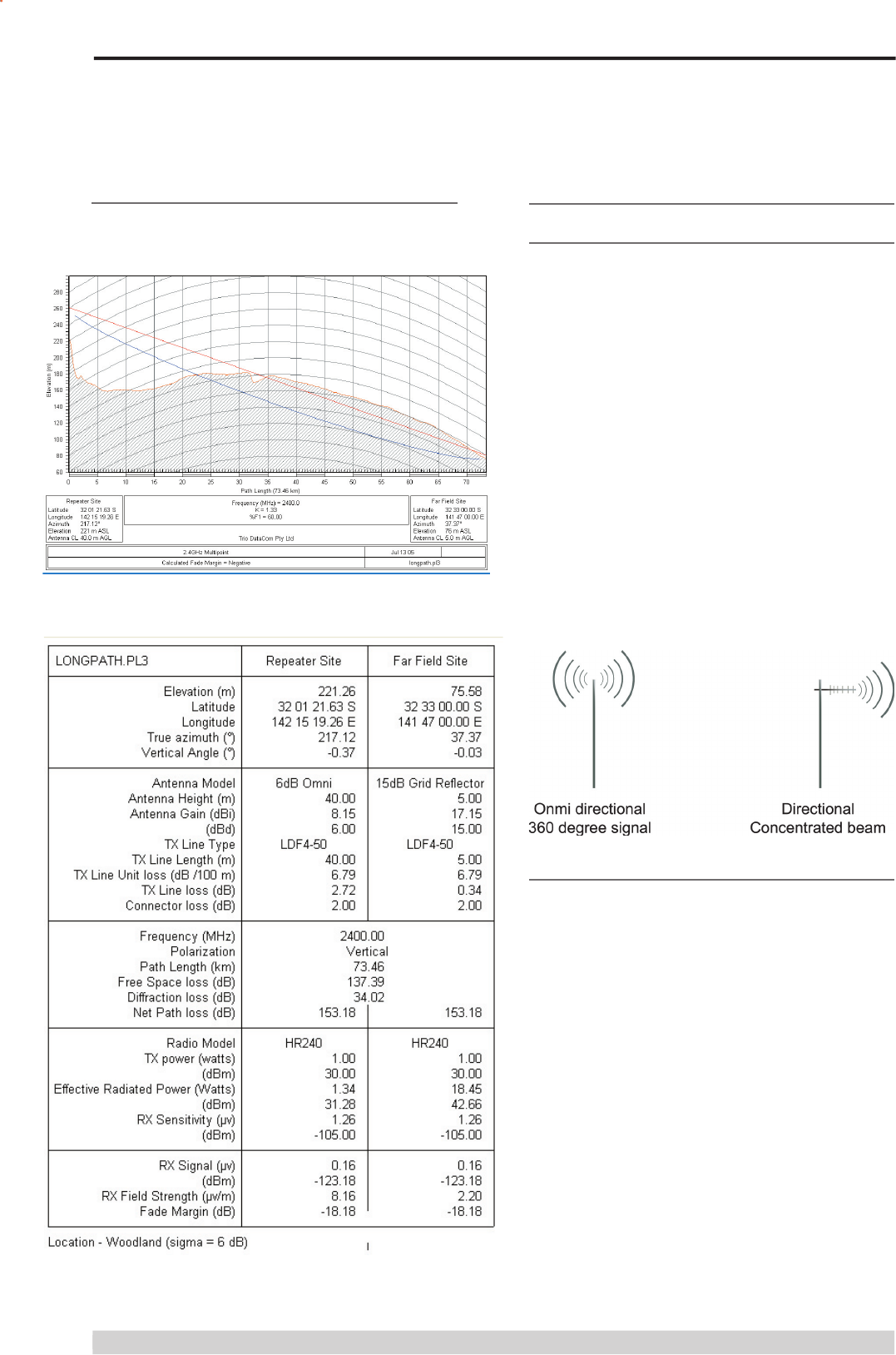
Examples of Predictive Path
Modelling
Clear line of site
Radio path with good signal levels, attenuated only by free space
loss.
Obstructed Radio Path
This path has an obstruction that will seriously degrade the signal
arriving at the fi eld site.
Page 11
© Copyright 2008 Trio DataCom Pty. Ltd.
O Series Data Radio – User Manual
Effect of Earth Curvature on Long Paths
This path requires greater mast height to offset the earth curvature
experienced at such a distance (73km).
Antenna Gain
By compressing the transmission energy into a disc or beam, the
antenna provides more energy (a stronger signal) in that direction,
and thus is said to have a performance “gain” over a basic omni
antenna. Gain is usually expressed in dBd, which is referenced
to a standard folded dipole. Gain can also be expressed in dBi,
which is referenced to a theoretical “isotropic” radiator. Either way,
if you intend to send and receive signals from a single direction,
there is advantage in using a directional antenna - both due to
the increased signal in the wanted direction, and the relatively
decreased signal in the unwanted direction (i.e. “interference
rejection” properties).
Selecting Antennas
Antennas
There are basically two types of antennas – omni-directional and
directional.
Omnidirectional antennas are designed to radiate signal in a 360
degrees segment around the antenna. Basic short range antennas
such as folded dipoles and ground independent whips are used
to radiate the signal in a “ball” shaped pattern. High gain omni
antennas such as the “co-linear” compress the sphere of energy
into the horizontal plane, providing a relatively fl at “disc” shaped
pattern which goes further because all of the energy is radiated in
the horizontal plane.
Directional antennas are designed to concentrate the signal into
a “beam” of energy for transmission in a single direction (i.e. for
point-to-point or remote to base applications).
Beamwidths vary according to the antenna type, and so can
be selected to suit design requirements. The most common
directional antenna is the yagi, which offers useable beam widths
of 15-40 degrees. Even higher “gain” is available using parabolic
“dish” type antennas such as gridpacks.

Page 12
© Copyright 2008 Trio DataCom Pty. Ltd.
O Series Data Radio – User Manual
Antenna Placement
When mounting the antenna, it is necessary to consider the
following criteria:
The mounting structure will need to be solid enough to withstand
additional loading on the antenna mount due to extreme wind, ice
or snow (and in some cases, large birds).
For omni directional antennas, it is necessary to consider the
effect of the mounting structure (tower mast or building) on the
radiation pattern. Close in structures, particularly steel structures,
can alter the radiation pattern of the antenna. Where possible,
omni antennas should always be mounted on the top of the mast
or pole to minimise this effect. If this is not possible, mount the
antenna on a horizontal outrigger to get it at least 1-2m away from
the structure. When mounting on buildings, a small mast or pole
(2-4m) can signifi cantly improve the radiation pattern by providing
clearance from the building structure.
For directional antennas, it is generally only necessary to consider
the structure in relation to the forward radiation pattern of the
antenna, unless the structure is metallic, and of a solid nature.
In this case it is also prudent to position the antenna as far away
from the structure as is practical. With directional antennas, it is
also necessary to ensure that the antenna cannot move in such
a way that the directional beamwidth will be affected. For long
yagi antennas, it is often necessary to install a fi breglass strut to
stablilise the antenna under windy conditions.
Alignment of Directional Antennas
This is generally performed by altering the alignment of the
antenna whilst measuring the received signal strength. If the
signal is weak, it may be necessary to pre-align the antenna using
a compass, GPS, visual or map guidance in order to “fi nd” the
wanted signal. Yagi antennas have a number of lower gain “lobes”
centred around the primary lobe. When aligning for best signal
strength, it is important to scan the antenna through at least 90
degrees, to ensure that the centre (strongest) lobe is identifi ed.
When aligning a directional antenna, avoid placing your hands or
body in the vicinity of the radiating element or the forward beam
pattern, as this will affect the performance of the antenna.
Common Cable Types Loss per 30.5m Loss per 30.5m
@ 915MHz @ 2.4GHz
RG213/U 7.4dB 23.6dB
FSJ1-50 (¼” superfl ex) 5.6dB 9.9dB
LDF4-50 (1/2” heliax) 2.2dB 2.3dB
LDF5-50 (7/8” heliax) 1.2dB 3.7dB
RF Feeders and Protection
The antenna is connected to the radio modem by way of an
RF feeder. In choosing the feeder type, one must compromise
between the loss caused by the feeder, and the cost, fl exibility, and
bulk of lower loss feeders. To do this, it is often prudent to perform
path analysis fi rst, in order to determine how much “spare” signal
can be allowed to be lost in the feeder. The feeder is also a critical
part of the lightning protection system.
All elevated antennas may be exposed to induced or direct
lightning strikes, and correct grounding of the feeder and mast are
an essential part of this process. Gas discharge lightning arresters
should also be fi tted to all sites.
Note: All ETSI installations require the use of a lightning surge
arrestor in order to meet EN6095.
Common Cable Types Loss per 30.5m Loss per 30.5m
RG213/U 7.4dB 23.6dB
FSJ1-50 (¼” superfl ex) 5.6dB 9.9dB
LDF4-50 (1/2” heliax) 2.2dB 2.3dB
LDF5-50 (7/8” heliax) 1.2dB 3.7dB
Common Cable Types Loss per 30.5m Loss per 30.5m
@ 915MHz @ 2.4GHz
RG213/U 7.4dB 23.6dB
FSJ1-50 (¼” superfl ex) 5.6dB 9.9dB
LDF4-50 (1/2” heliax) 2.2dB 2.3dB
LDF5-50 (7/8” heliax) 1.2dB 3.7dB
TX Power for Maximum EIRP (FCC)
FCC Regulations allow up to 36 dBm effective isotropic radiated
power (EIRP). To calculate the maximum transmitter power you
need to know the gain of the antenna being used (see the FCC
Approved Antenna List Appendix) and the cabling loss. The
maximum transmitter power can then be calculated using the
following formula:
Maximum transmitter power (dBm) = 36dBm + cable loss (dB)
– antenna gain (dBd) - 2.15.
As an example, if we choose the BMY890K yagi from the FCC
Approved Antenna List which has a gain of 10dBd and we know
the cable loss is 3dB then the maximum output power is:
Maximum output power (dBm) = 36 + 3 -10 - 2.15 = 26.85 dBm.
Rounded down to 26dBm. Therefore the radio TX power should be
set to 26dBm.
Other countries may have different EIRP limits, but the same
method for calculation applies.
FCC Point to Point : More EIRP may be allowed for fi xed point to
point links. With the transmitter set to 27dBm, an antenna gain
(subtracting cable loss) of up to 15 dBi is allowed. For antenna
gains of more than 15 dBi in a fi xed point to point link, the power
must be backed off from 27dBm by 1dB for every 3dB the antenna
gain exceeds 15dBi.
ETSI Maximum EIRP for the 2.4GHz band is +20dBm.
Page 13
© Copyright 2008 Trio DataCom Pty. Ltd.
O Series Data Radio – User Manual
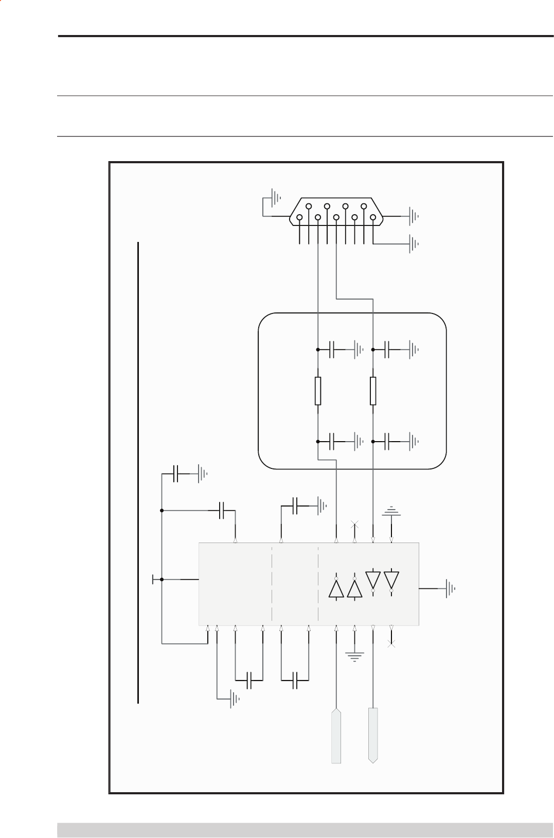
PORT A RS232 SERIAL INTERFACE- SIMPLE APPLICATION
C8
100p
R2
100R
C9
100p
C6
100p
R1
100R
C7
100p
RXD_A
TXD_A
+3V3
Radio PIN 2
Radio PIN 1
C1
100n
C2
100n
C4
100n
1
6
2
7
3
8
4
9
5
M2 M1
PORT A
C3
100n
C5
100n
Optional EMC Components
C1+
2
C1-
4
C2+
5
C2-
6
Vs+ 3
Vs- 7
VCC 17
GND
16
T1in
12 T1out 15
T2in
11 T2out 8
R1out
13 R1in 14
R2out
10 R2in 9
nEN
1nSHDN
20
U1
MAX3222E
note: Radio inputs are 5V tolerant, however 3V3 RS232 is recommended
Part F – Suggested Interface Circuits
Port A RS232 Serial Interface
Page 14
© Copyright 2008 Trio DataCom Pty. Ltd.
O Series Data Radio – User Manual
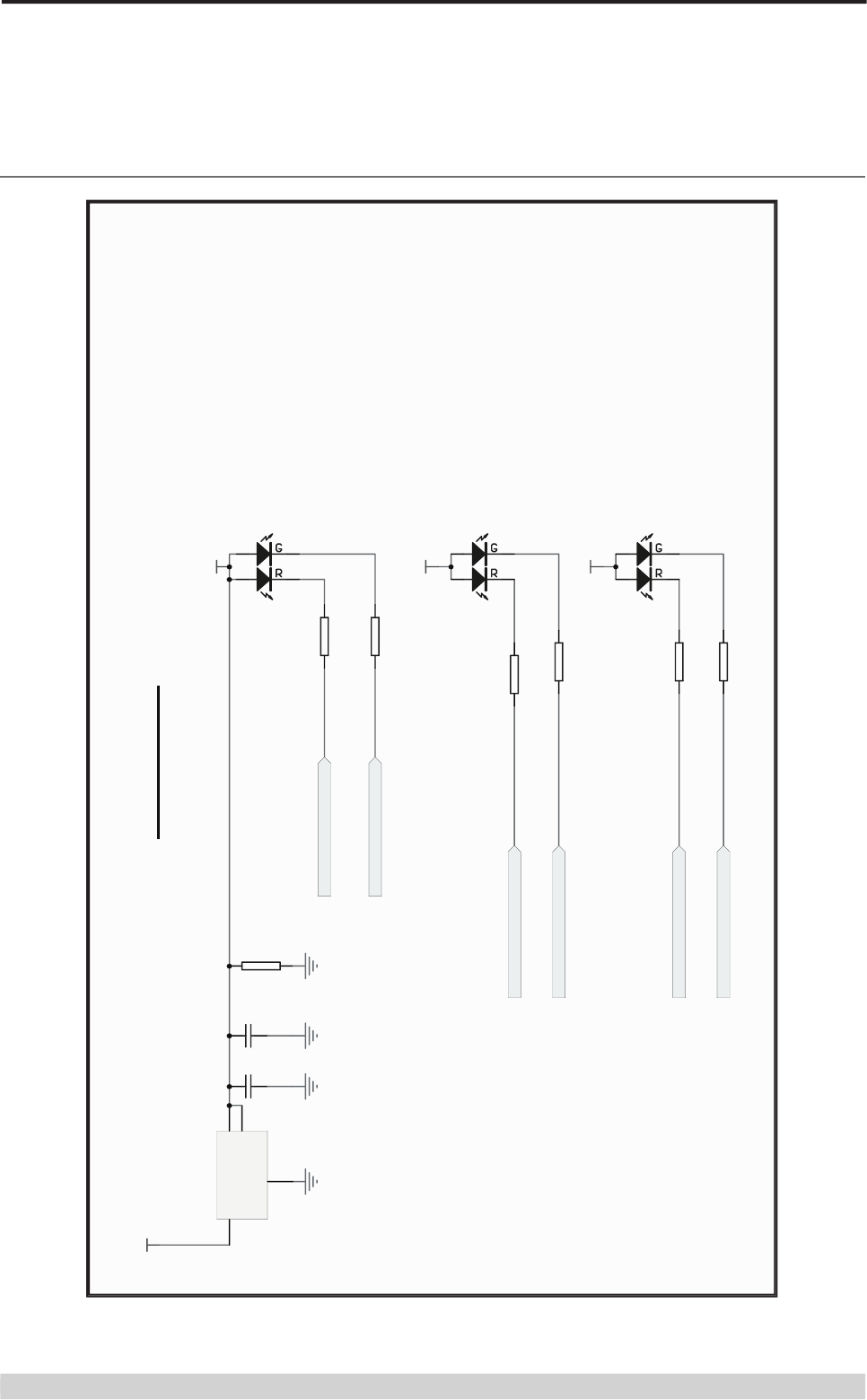
STATUS LEDS
+3v3_LED
+3v3_LED
"Tx" = red, "Pwr" = green (default condition)
"RxSIG" = red, "Sync" = green
FROM RADIO MODULE
+3v3_LED
"TxD" = red, "RxD" = green, BOTH "TX & RX" = amber
POWER-LED PIN 22
Radio Rx-SYNC-LED PIN 17
Radio Tx-LED PIN 15
PORTA-TXD-LED PIN 20
PORTA-RXD-LED PIN 21
Radio RX SIG-LED PIN 39
R80
390R
R81
51R
R82
390R
R83
51R
R86
390R
R87
51R
R84
1K
+5V2
34
12
H1
KPBL-3025SURKMGKC
34
12
H2
KPBL-3025SURKMGKC
34
12
H4
KPBL-3025SURKMGKC
VIN
3
GND
1
VOUT 2
VOUT 4
Status LEDs Interface