Schneider Electric Systems Canada OM240 2.4GHz frequency hopping spread spectrum rf module User Manual O Series 08 08 indd
Trio Datacom Pty Ltd (a wholly owned company of Schneider Electric) 2.4GHz frequency hopping spread spectrum rf module O Series 08 08 indd
Contents
- 1. Users Manual 1
- 2. Users Manual 2
Users Manual 2
Page 15
© Copyright 2008 Trio DataCom Pty. Ltd.
O Series Data Radio – User Manual
SERIAL INTERFACE
DiagsIn
C6
100p
R1
100R
C7
100p
DiagsOut
+3V3
C1
100n
C2
100n
C3
100n
C4
100n
C5
100n
Radio PIN 7
Radio PIN 8
Radio PIN 24
SYSTEM RS232
nPTT
M1
M2
P1
1
P2
2
P3
3
P4
4
P5
5
P6
6
P8
8
J1
J2
J3
J4
J5
J6
J7
J8
P7
7
X1
C1+
2
C1-
4
C2+
5
C2-
6
Vs+ 3
Vs- 7
VCC 17
GND
16
T1in
12 T1out 15
T2in
11 T2out 8
R1out
13 R1in 14
R2out
10 R2in 9
nEN
1nSHDN
20
U1
MAX3222E C10
100p
R4
100R
C11
100p
C8
100p
R2
100R
C9
100p
R3
3K3
+3V3
note: Radio inputs are 5V tolerant, however 3V3 is recommended.
Optional EMC components
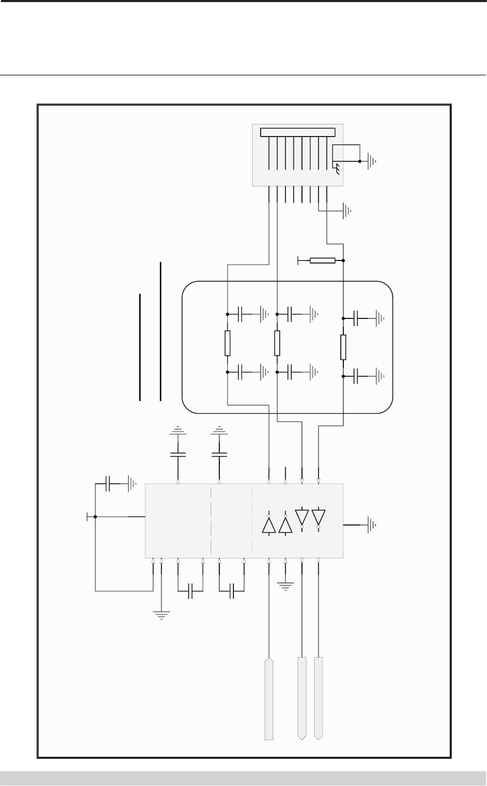
System Port Interface
Page 16
© Copyright 2008 Trio DataCom Pty. Ltd.
O Series Data Radio – User Manual
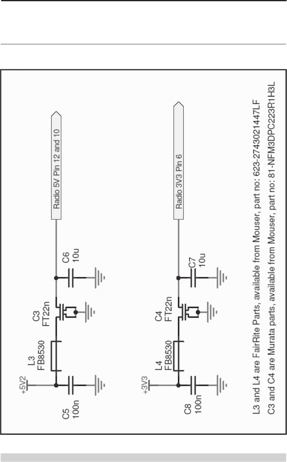
Power Supply Filtering
Page 17
© Copyright 2008 Trio DataCom Pty. Ltd.
O Series Data Radio – User Manual
Part G – Mounting and LED Indicators
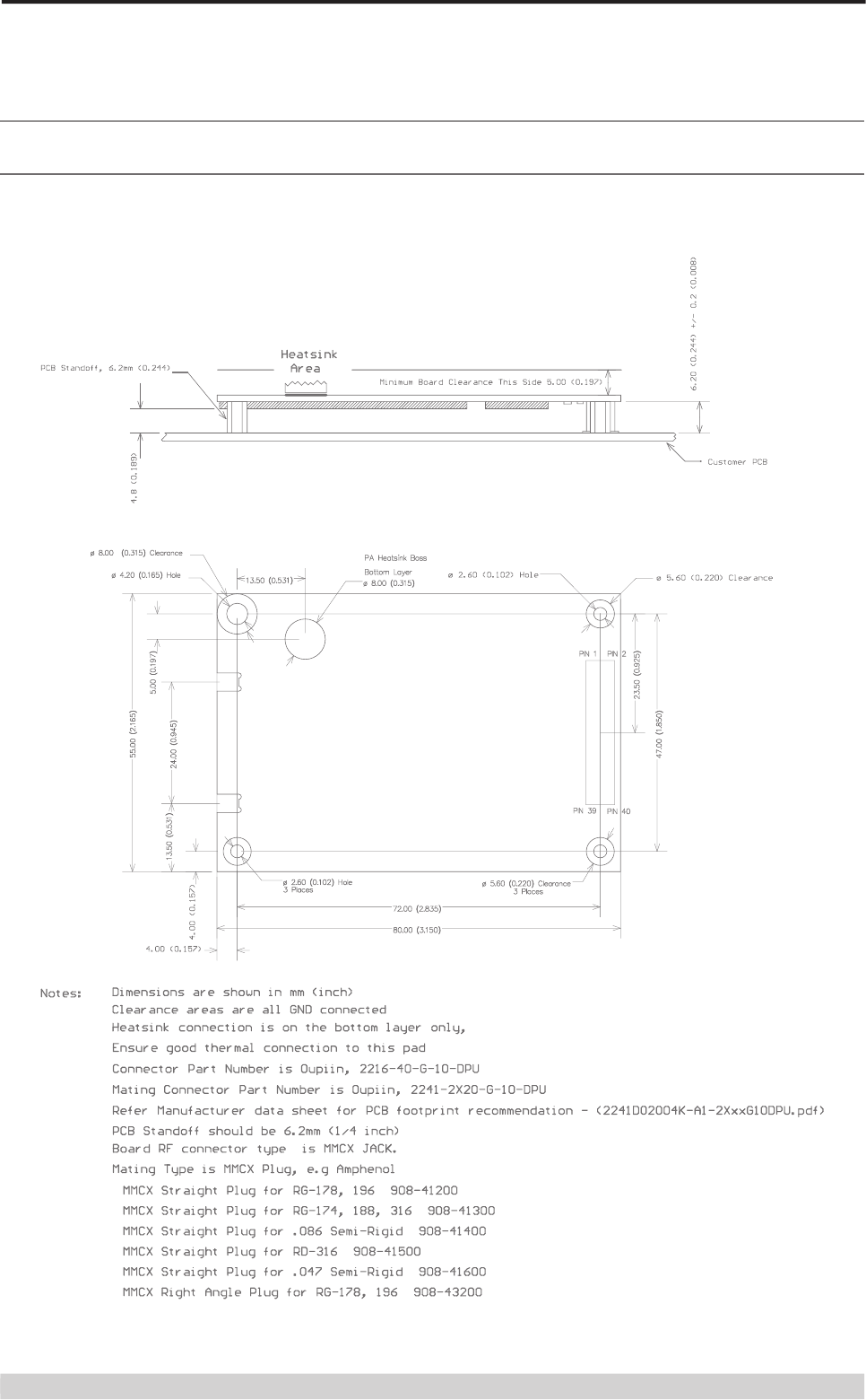
Mounting & Connector Information
Please Note : Mating connectors can be supplied with each radio or seperately. Please order as part number SM%CO2241-20X2
Page 18
© Copyright 2008 Trio DataCom Pty. Ltd.
O Series Data Radio – User Manual
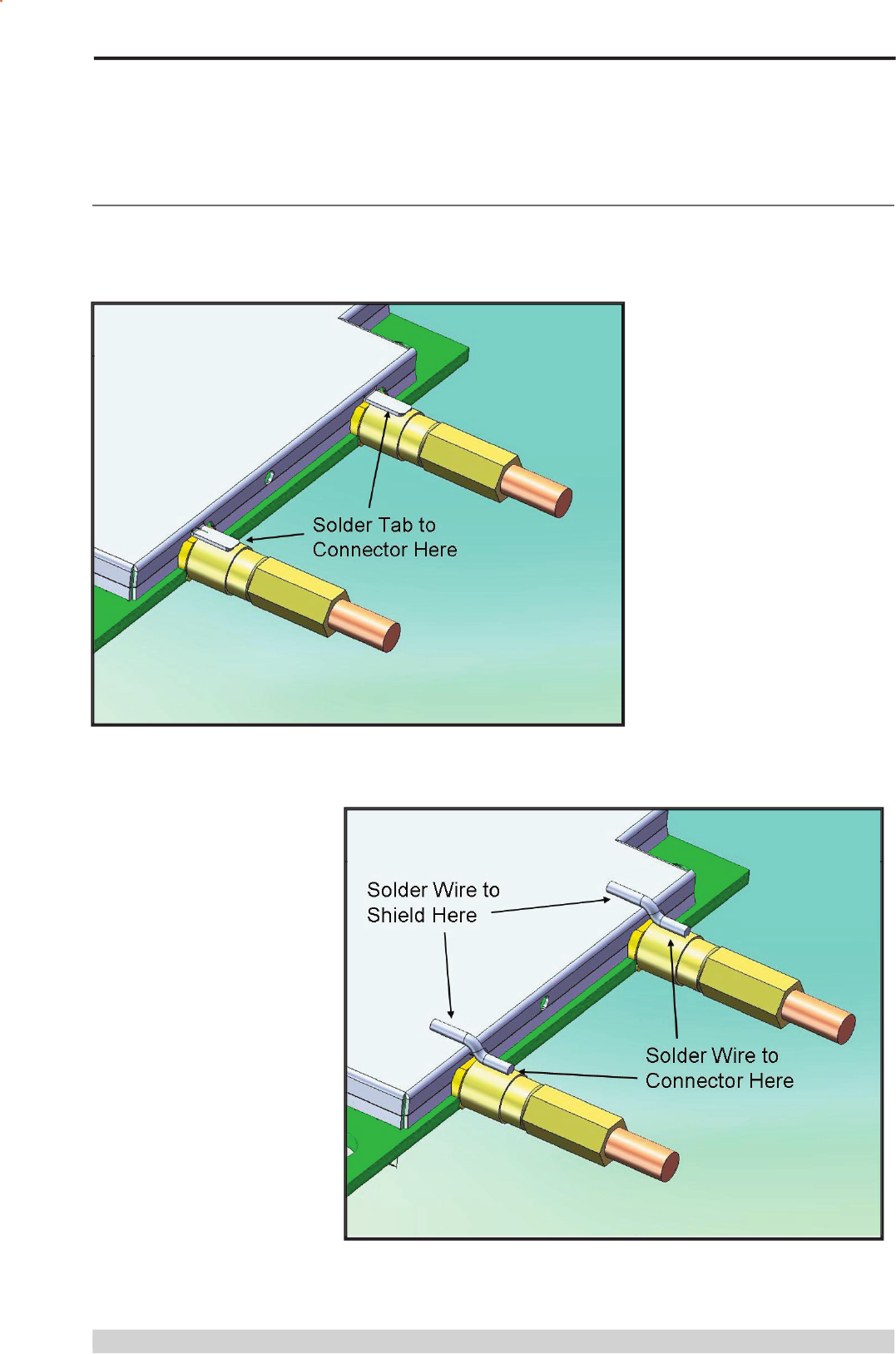
Antenna Port Cabling (Hazardous Installations)
When the O Series OEM module is intended to be used in equipment which is compliant with Class I, Division 2 - Groups A,B,C,D Hazardous
Locations, the antenna conenctors need to be retained using a soldered connection as shown in the diagrams below. The method of soldered
retention will depend on the model of O Series OEM product in use. See below for model specifi c guidlines.
For O Series modules that have integtel mounting tabs, solder the TAB to the RF connector.
For O Series modules that have no TAB, solder a wire from the shield lid to the connector.
Page 19
© Copyright 2008 Trio DataCom Pty. Ltd.
O Series Data Radio – User Manual
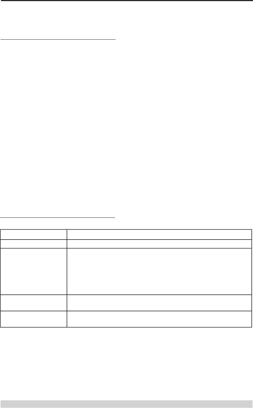
LED Indicators
Indicators
Legend
Power LED
Tx Power (Red) / DC Power (Green)
Sync/NoRx LED
Masters:
100ms pulse when user data received (Green)
Remotes/Bridges:
Pulsed every 1500ms for 100ms when master acquired, additional 100ms
pulse when user data received (Green)
Pulsed every 1500ms for 100ms when master not acquired (Red)
Port A Activity
Pulsed for 100ms for any TxD activity on Port A TXD (Red)
Pulsed for 100ms for any RxD activity on Port A RXD (Green)
Port B Activity
Pulsed for 100ms for any TxD activity on Port BA TXD (Red)
Pulsed for 100ms for any RxD activity on Port B RXD (Green)
Product Labelling
When this OEM module is housed inside another unit, the unit
must be labelled with the following notice :
“This unit contains a device with FCC ID:
900MHz Modules:
NI8OM900 and IC: 4630A-OM900.
2.4GHz Modules:
NI8OM240 and IC: 4630A-OM240.
This device complies with part 15 of the FCC rules. Operation of
this device is subject to the following conditions:
(1) this device may not cause harmful interference, and (2) this
must accept any interference received, including interference that
may cause any undesired operation.”

Page 20
© Copyright 2008 Trio DataCom Pty. Ltd.
O Series Data Radio – User Manual
Part H – Programming and Diagnostics
Programming
The O Series OEM module is programmed via the System Port.
There are two methods of programming:
(a) In Situ : Programming via the 3-wire System Port pins
(b) In K-Series : OEM Module can be plugged into a K Series
carrier PCB and programmed via the System Port on the K
Series.
The O Series OEM module is programmed using the TVIEW+
Management Suite : K Series programmer.
Programming of the O Series is similar to the K Series - however
some features are optional on the O-Series (dependent on external
support circuitry). The features that require external support
circuitry which may or may not be relavent to your design are:
(a) RS-485 .
(b) Multi-master Synchronisation.
(c) RSSI Output
(d) Port B
(a) Port A & B Hardware handshaking signals
For a comprehensive guide to programming the O Series OEM
module, please refer to the TVIEW+ K Series User Manual - Part
G.
Diagnostics
The O Series OEM module includes diagnostics which is useful for
fault fi nding and system commisioning. Detailed information about
O Series diagnostics is available in the TVIEW+ Diagnostics User
Manual.
TVIEW+ Diagnostics is available via the System Port of the O
Series module. To access the diagnostics facilities locally, the
System Port of the O Series must be brought out to a connector for
connecion to the computer running the diagnostics package.
Alternatively, remote diagnostics connectivity is available “over-the-
air”. More information on confi guring diagnostics can be found in
both the TVIEW+ Diagnostics User Manual and the K Series User
Manual.
The OEM user may also wish to integrate O Series diagnostics
into their own application. To facilitate this, Trio Datacom can
provide the specifi cations document for the “Remote Diagnostics
Protocol”. This document specifi es how diagnostics messages
are constructed and what facilities are available. To obtain this
document, please contact the factory on support@triodatacom.
com.
Page 21
© Copyright 2008 Trio DataCom Pty. Ltd.
O Series Data Radio – User Manual
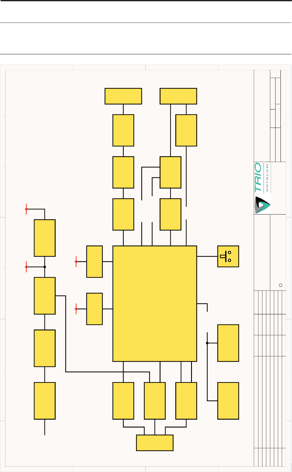
Part I – K Series PCB Overlay & Schematics
1
1
2
2
3
3
4
4
5
5
6
6
7
7
8
8
D D
C C
B B
A A
TRIO DATACOM Pty. Ltd.
41 Aster Avenue.
ISSUE CHANGE DETAILS DRAWN DATEECO No.
3 9
K-Series Block Diagram
D1
TITLE:
SIZE
A3
DATE:
SHT: OF
FILE:
CHKD:
DWG No.:
195-00-100-Block.SchDoc
11-Jul-07
REV:
195-00-100
THIS DRAWING IS CONFIDENTIAL INFORMATION
Disclosure of this information, whether all or part thereof, cannot be
made to a 3rd party without the written consent of Trio Datacom
Pty. Ltd. Trio Datacom Pty. Ltd. reserves the right to change
documentation in the light of technical advancement.
COPYRIGHT
C
PCB No. REV.
DRN: P Hogan RG
Carrum Downs.
Victoria. Australia. 3201
A2
A3
A3
B2
C1
D1
B1
See Bugzilla Bug # Upissued to A2 and frozen
Upissued to A3
See Bugzilla Bug # 2696, 2748,2757, 2770,2819, 2872, 2876, 2877
Up issued to B1 and frozen.
Bugs 2990, 2993, 3001: R80-83,86-89=100R. NF parts fixed. Q6=NF.
PCB Rev C and schematic update. See ECN.
N/A
N/A
N/A
N/A
N/A
G. Rankin
G. Rankin
G. Rankin
G. Rankin
BWA
BWA
PAH
21/02/07
22/03/07
22/03/07
22/03/07
23/05/07
30/05/07
19/06/07PCB Rev D Schematic update see ECN sheet
195-01-100 D
2007
+5V +3.3V
+5V +3.3V
GP INPUT
GP OUTPUT
INPUT
INPUT INPUT
FILTER
FILTER FILTER
CROWBAR
CIRCUIT
(10-30V)
to 5V 5V to 3.3V
REGULATOR
REGULATOR
LINK LINK
LINK
FIELDS FIELDS
FIELDS
RS-232
RS-232 RS-232/RS-485
DRIVERS
DRIVERS
DRIVERS
SHUTDOWN
SIO
SYSTEM PORT
PORT APORT B
O-SERIES MODULE
TEMPERATURE
SENSOR NVRAMFACTORY
DEFAULTS
SWITCH
I2C BUS
10-30v
(U1) (U2)(Q2)(FL1)
(U7) (U7) (U9)
(U6)
(U4) (U5)
RSSI
(X7) (X10) (X6) (X8)
(X5)
LINK
FIELDS
(X4)
SW1
(X11) (X2)
(X1)
(X9)
Schematics
Page 22
© Copyright 2008 Trio DataCom Pty. Ltd.
O Series Data Radio – User Manual
1
1
2
2
3
3
4
4
5
5
6
6
7
7
8
8
D D
C C
B B
A A
TRIO DATACOM Pty. Ltd.
41 Aster Avenue.
ISSUE CHANGE DETAILS DRAWN DATEECO No.
5 9
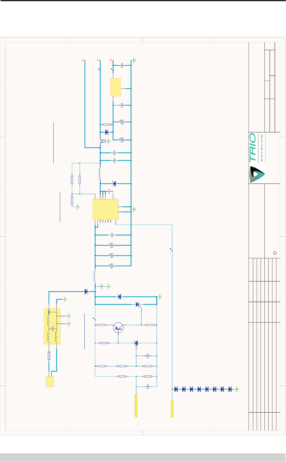
K-Series PSU
D1
TITLE:
SIZE
A3
DATE:
SHT: OF
FILE:
CHKD:
DWG No.:
195-00-100-PSU.SchDoc
11-Jul-07
REV:
195-00-100
THIS DRAWING IS CONFIDENTIAL INFORMATION
Disclosure of this information, whether all or part thereof, cannot be
made to a 3rd party without the written consent of Trio Datacom
Pty. Ltd. Trio Datacom Pty. Ltd. reserves the right to change
documentation in the light of technical advancement.
COPYRIGHT
C
PCB No. REV.
DRN: P Hogan RG
Carrum Downs.
Victoria. Australia. 3201
A2
A3
A3
B2
C1
D1
B1
See Bugzilla Bug # Upissued to A2 and frozen
Upissued to A3
See Bugzilla Bug # 2696, 2748,2757, 2770,2819, 2872, 2876, 2877
Up issued to B1 and frozen.
Bugs 2990, 2993, 3001: R80-83,86-89=100R. NF parts fixed. Q6=NF.
PCB Rev C and schematic update. See ECN.
N/A
N/A
N/A
N/A
N/A
G. Rankin
G. Rankin
G. Rankin
G. Rankin
BWA
BWA
PAH
21/02/07
22/03/07
22/03/07
22/03/07
23/05/07
30/05/07
19/06/07PCB Rev D Schematic update see ECN sheet
195-01-100 D
C39
100p
keep separated !
R29
1K
TP2
POWER INPUT
(10~30VDC)
VSW
FB
VINSW
VIN+
VIN-
POWER SUPPLIES
Input Filter & Protection
Step-Down Switcher
R34
1K
R30
2K2
R32
10K
VINF
R33
1K
1
3 2
Q1
BC857W
R37
220R
SCRgate
Vset (Total ESR = 100mOHM)
C49
1u
TP1
R31
10K
(ESR = 65mOHM per cap)
C43
220n
C44
100u
C45
100u
2007
IN
3FB 7
IN
2
VSW 13
CB 4
GND
9
VSW 14
EN
8
VSW 12
DAP
nc
5
nc
6
nc
1
nc
11
nc
10
DAP
U1
LM2676SD-ADJ
SUPPLY-MONITOR
+5V2
1
3 4
2
5
6
B
PSG
CB
CG
FL1
BNX012-01
D3
SMCJ33A
3 1
2U3
LM431
AK
D1
SS26
A K
D2
SS26
C35
10n
R27
NF (68K)
R28
3K3
23
1
Q2
MCR708AT4G
1
2
X3
F1
3A
L1
22uH
L2
47uH
R52
15K
R53
1K
ENABLE
+3V3
AK
D12
SS26
R22
NF (0R0) TP3
TP4
12 3
D13
BAV99W
12 3
D14
BAV99W
12 3
D15
BAV99W
12 3
D16
BAV99W
C67
1n
HIGH=ENABLE
C1
10u
C2
10u
VIN
3
GND
2
VOUT 1
U2
LP38690DT-3.3
+5V2-MOD
C36
FT22n
C40
56u 35V
C41
56u 35V
C42
NF (56u 35V)
C75
1000u 6.3V
C66
1000u 6.3V
Page 23
© Copyright 2008 Trio DataCom Pty. Ltd.
O Series Data Radio – User Manual
1
1
2
2
3
3
4
4
5
5
6
6
7
7
8
8
D D
C C
B B
A A
TRIO DATACOM Pty. Ltd.
41 Aster Avenue.
ISSUE CHANGE DETAILS DRAWN DATEECO No.
6 9
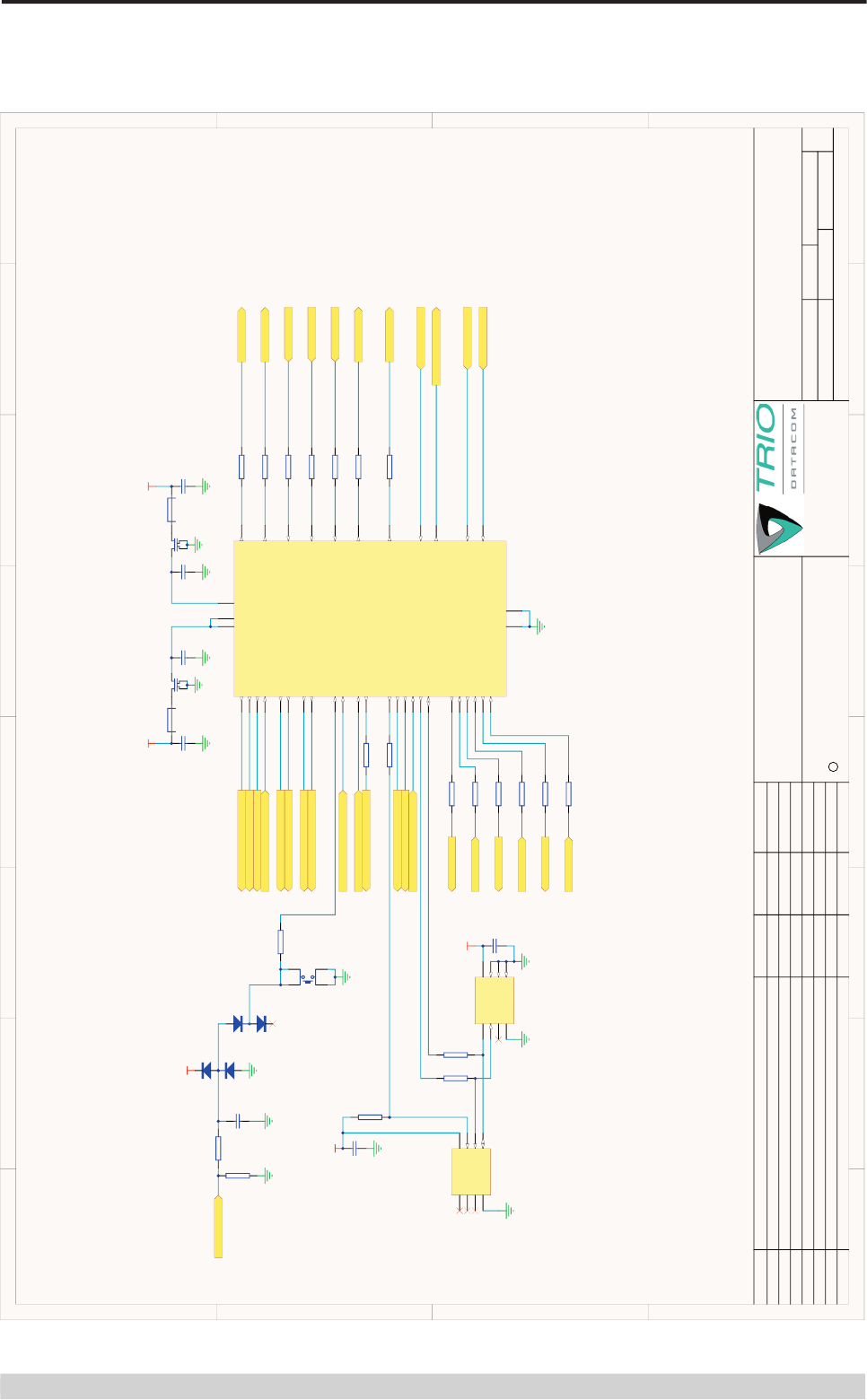
K-Series RF Module
D1
TITLE:
SIZE
A3
DATE:
SHT: OF
FILE:
CHKD:
DWG No.:
195-00-100-RadioModule.SchDoc
11-Jul-07
REV:
195-00-100
THIS DRAWING IS CONFIDENTIAL INFORMATION
Disclosure of this information, whether all or part thereof, cannot be
made to a 3rd party without the written consent of Trio Datacom
Pty. Ltd. Trio Datacom Pty. Ltd. reserves the right to change
documentation in the light of technical advancement.
COPYRIGHT
C
PCB No. REV.
DRN: P Hogan RG
Carrum Downs.
Victoria. Australia. 3201
A2
A3
A3
B2
C1
D1
B1
See Bugzilla Bug # Upissued to A2 and frozen
Upissued to A3
See Bugzilla Bug # 2696, 2748,2757, 2770,2819, 2872, 2876, 2877
Up issued to B1 and frozen.
Bugs 2990, 2993, 3001: R80-83,86-89=100R. NF parts fixed. Q6=NF.
PCB Rev C and schematic update. See ECN.
N/A
N/A
N/A
N/A
N/A
G. Rankin
G. Rankin
G. Rankin
G. Rankin
BWA
BWA
PAH
21/02/07
22/03/07
22/03/07
22/03/07
23/05/07
30/05/07
19/06/07PCB Rev D Schematic update see ECN sheet
195-01-100 D
R5 220R
R9 220R
R6 220R
R8 220R
MULTISYNC-INPUT
R10 220R
R12 220R
R11 220R
R7 220R
PORTB-RXD
PORTB-CTS
PORTB-TXD
PORTB-RTS
nSHUTDOWN-IN
PORTB-DCD
RSSI-OUT
PTT
2007
Tx-INHIBIT
MODULE-DIAGS-SER-IN
MODULE-DIAGS-SER-OUT
PORTB-DTR
R17 220R
R15 220R
MODULE-Rx-SYNC-LED
MODULE-Tx-LED
MODULE-DC-POW-LED
+3V3
L4
FB8530
Radio Module
MULTISYNC-OUTPUT
L3
FB8530
+5V2-MOD
C5
100n
C8
100n
C6
10u
C7
10u
R16 220R
R4
220R
R18 220R
R20 220R
R19 220R
R14 220R
PORTA-RXD
PORTA-CTS
PORTA-TXD
PORTA-RTS
PORTA-DCD
PORTA-DTR
nSHUTDOWN-OUT
SUPPLY-MONITOR
+3V3
Restore Defaults
SDA
1
SCL
2
OS
3
GND
4A2 5
A1 6
A0 7
VCC 8
U4
NF (LM75A) +3V3
C9
100n
R1
220R
R2
220R
PORTB-RXD-LED
MODULE-RX-SIG-LED
PORTB-TXD-LED
PORTA-TXD-LED
PORTA-RXD-LED
SDA 5
SCL 6
WP 7
GND
4NC
3NC
2NC
1VCC 8
U5
24LC01
+3V3
C69
100n
GP-INPUT
NVRAM
TEMPERATURE
SENSOR
1 2
3 4
SW1
SKQLLA
1 23
D18
BAV99W
12 3
D19
BAV99W
TEST-MODE
PORT2-RxD 2
PORT2-TxD 1
PORT2-DCD 9
PORT2-DTR 5
PORT2-RTS 4
PORT2-CTS 3
PORT0-SysSerOut
8PORT0-SysSerIn
7
VCC 6
PAVCC 10
PAVCC 12
GND
11
GND
14
HOP-SYNC-INPUT 27
RxD-PORT2-LED
21
ANALOG-RSSI 13
Tx-LED
15 SYNC-LED
17
ANALOGUE-INPUT
16
TxD-PORT1-LED
18
RxD-PORT1-LED
19
DC-POW-LED
22
nFACT/TEST-MODE
23
PTT
24
Tx-INHIBIT 25
SHUTDOWN-IN 26
HOP-SYNC-OUTPUT 28
PORT1-TxD
29 PORT1-RxD
30 PORT1-RTS
31 PORT1-CTS
32 PORT1-DTR
33 PORT1-DCD
34
TWD
35 TWCK
36 SUPPLY-MONITOR
37 SHUTDOWN-OUT
38 RxSIG-LED
39 NVRAM-WP
40
TxD-PORT2-LED
20
X9
R21
10K
NVRAM-WP
C3
FT22n
C4
FT22n
R3
4K7
R107
4K7 C81
100n
Page 24
© Copyright 2008 Trio DataCom Pty. Ltd.
O Series Data Radio – User Manual
1
1
2
2
3
3
4
4
5
5
6
6
7
7
8
8
D D
C C
B B
A A
TRIO DATACOM Pty. Ltd.
41 Aster Avenue.
ISSUE CHANGE DETAILS DRAWN DATEECO No.
8 9
K-Series RS-232 Port B
D1
TITLE:
SIZE
A3
DATE:
SHT: OF
FILE:
CHKD:
DWG No.:
195-00-100-RS232PORTB.SchDoc
11-Jul-07
REV:
195-00-100
THIS DRAWING IS CONFIDENTIAL INFORMATION
Disclosure of this information, whether all or part thereof, cannot be
made to a 3rd party without the written consent of Trio Datacom
Pty. Ltd. Trio Datacom Pty. Ltd. reserves the right to change
documentation in the light of technical advancement.
COPYRIGHT
C
PCB No. REV.
DRN: P Hogan RG
Carrum Downs.
Victoria. Australia. 3201
A2
A3
A3
B2
C1
D1
B1
See Bugzilla Bug # Upissued to A2 and frozen
Upissued to A3
See Bugzilla Bug # 2696, 2748,2757, 2770,2819, 2872, 2876, 2877
Up issued to B1 and frozen.
Bugs 2990, 2993, 3001: R80-83,86-89=100R. NF parts fixed. Q6=NF.
PCB Rev C and schematic update. See ECN.
N/A
N/A
N/A
N/A
N/A
G. Rankin
G. Rankin
G. Rankin
G. Rankin
BWA
BWA
PAH
21/02/07
22/03/07
22/03/07
22/03/07
23/05/07
30/05/07
19/06/07PCB Rev D Schematic update see ECN sheet
195-01-100 D
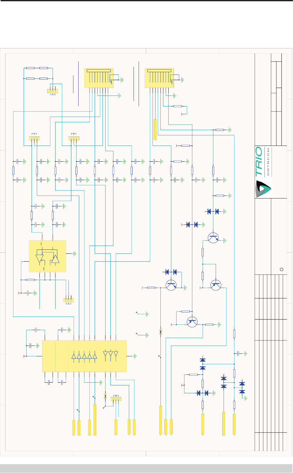
PORT B RS232 SERIAL INTERFACE
C23
100p
R35
100R
C24
100p
C25
100p
R38
100R
C26
100p
C27
100p
R40
100R
C28
100p
CTS-B
RTS-B
DSR-B
C12
100p
R23
100R
C13
100p
C15
100p
R24
100R
C16
100p
C19
100p
R25
100R
C20
100p
C21
100p
R26
100R
C22
100p
DTR-B
RXD-B
TXD-B
DCD-B
+3V3
PORTB-RXD
PORTB-TXD
PORTB-DTR
PORTB-CTS
PORTB-RTS
2007
R45
NF (10K)
R43
NF (22K)
+5V2
GP-INPUT
C10
100n
C11
100n
C14
100n
C17
100n
C18
100n
1 23
D4
NF (BAV99W)
1
2
3
5
4
U8
LMV321IDCKR
R39
47K
+3V3
PORTB-DCD
C1+
10
C1-
12
C2+
13
C2-
14
V+ 11
V- 15
VCC 9
T1-IN
7T1-OUT 2
T2-IN
6T2-OUT 3
R1-OUT
5R1-IN 4
R2-OUT
17 R2-IN 16
GND
8
R2-OUT
22 R2-IN 23
T1-IN
18 T1-OUT 1
T2-IN
19 T2-OUT 24
T1-IN
21 T1-OUT 20
U6
ICL3207IAZ
User-Out
RSSI-OUT
C70
100n
R92
NF (100R)
A K
D17
NF (SMBJ24A)
MULTISYNC-INPUT
R69
1K8
R70
3K3
R66
3K9
R60
39K
R72
15K
R75
15K
+5V2
R61
100R
+5V2
MULTISYNC-OUTPUT
C64
100p 1
32
Q5
BC817W
1
3 2
Q4
BC857W
1 23
D11
BAV99W
1
3 2
4
Q6
NF (BSP-295)
C29
NF (1n)
C73
NF
C74
NF
C71
1n
C68
1n
R77
220K
R36
470K
R90
NF (47K)
R41
47K
R42
47K
1
6
2
7
3
8
4
9
5
M2 M1
X4
1
2
3
5
4
U10
NF (LMV321IDCKR)
+3V3
1
32
Q9
BC817W
R85
3K9
R106
3K3
R100
2K2
1 23
D20
BAV99W
R99
2K2
R105
270R
+5V2
R104
270R
R103
270R
R102
270R
R101
270R
1 2
3 4
5 6
7 8
X11
HDR4X2
C80
100p
GPS
Multisync
GP-Out
User-RSSI
Page 25
© Copyright 2008 Trio DataCom Pty. Ltd.
O Series Data Radio – User Manual
1
1
2
2
3
3
4
4
5
5
6
6
7
7
8
8
D D
C C
B B
A A
TRIO DATACOM Pty. Ltd.
41 Aster Avenue.
ISSUE CHANGE DETAILS DRAWN DATEECO No.
7 9
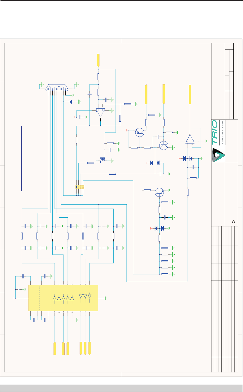
K-Series RS-232 System Port and Port A
D1
TITLE:
SIZE
A3
DATE:
SHT: OF
FILE:
CHKD:
DWG No.:
195-00-100-RS232SYSTEM-PORTA.SchDoc
11-Jul-07
REV:
195-00-100
THIS DRAWING IS CONFIDENTIAL INFORMATION
Disclosure of this information, whether all or part thereof, cannot be
made to a 3rd party without the written consent of Trio Datacom
Pty. Ltd. Trio Datacom Pty. Ltd. reserves the right to change
documentation in the light of technical advancement.
COPYRIGHT
C
PCB No. REV.
DRN: P Hogan RG
Carrum Downs.
Victoria. Australia. 3201
A2
A3
A3
B2
C1
D1
B1
See Bugzilla Bug # Upissued to A2 and frozen
Upissued to A3
See Bugzilla Bug # 2696, 2748,2757, 2770,2819, 2872, 2876, 2877
Up issued to B1 and frozen.
Bugs 2990, 2993, 3001: R80-83,86-89=100R. NF parts fixed. Q6=NF.
PCB Rev C and schematic update. See ECN.
N/A
N/A
N/A
N/A
N/A
G. Rankin
G. Rankin
G. Rankin
G. Rankin
BWA
BWA
PAH
21/02/07
22/03/07
22/03/07
22/03/07
23/05/07
30/05/07
19/06/07PCB Rev D Schematic update see ECN sheet
195-01-100 D
SERIAL INTERFACE
R73
100R
C63
100p
nShutdown
DiagsIn
C59
100p
R55
100R
C60
100p
C62
100p
TxInhibit
DiagsOut
+3V3
Tx-INHIBIT
ENABLE
2007
nSHUTDOWN-OUT
nSHUTDOWN-IN
C32
100n
C33
100n
C38
100n
C46
100n
C47
100n
C1+
10
C1-
12
C2+
13
C2-
14
V+ 11
V- 15
VCC 9
T1-IN
7T1-OUT 2
T2-IN
6T2-OUT 3
R1-OUT
5R1-IN 4
R2-OUT
17 R2-IN 16
GND
8
R2-OUT
22 R2-IN 23
T1-IN
18 T1-OUT 1
T2-IN
19 T2-OUT 24
T1-IN
21 T1-OUT 20
U7
ICL3207IAZ
1 23
D7
NF (BAV99W)
1 23
D6
NF (BAV99W)
1 23
D9
NF (BAV99W)
R62
NF (22K)
R65
NF (22K)
R76
22K
R63
NF (22K)
R74
470R
+3V3
C53
100p
R50
100R
C54
100p
C55
100p
R51
100R
C56
100p
C57
100p
R54
100R
C58
100p
C30
100p
R46
100R
C31
100p
C48
100p
R48
100R
C50
100p
CTS-A
RTS-A
DSR-A
DTR-A
RXD-A
TXD-A
DCD-A
PORTA-DCD
PORTA-RXD
PORTA-TXD
PORTA-DTR
PORTA-CTS
PORTA-RTS
1 23
D5
BAV99W
1 23
D8
BAV99W
1 23
D10
BAV99W
1
32
Q3
BC817W
+3V3
+3V3
R56
22K
R67
22K
R57
22K
R59
22K
R68
22K
MODULE-DIAGS-SER-IN
MODULE-DIAGS-SER-OUT
PTT
C61
100p
PORTA-RXD
RS485-TXD
PORTA-DCD
RS-485
RS-232
C34
100p
R47
100R
C37
100p
C51
100p
R49
100R
C52
100p
PORT A
R91
10K
C72
100n
+5V2
PORTA-DCD
PORTA-RXD
RS485-TXD
RS-485
RS-232
RS-485
RS-232
RS-485
RS-232
C65
220n
R13
4K7
SERIAL INTERFACE
SYSTEM RS232
Term
Unterm
R93
100R
R94
100R
R95
100R
R96
100R
C76
NF
C77
NF
C78
NF
C79
NF
R78
0R0
R79
0R0
1
2
3
X10
1
2
3
X7
1
2
3
X6
1
2
3
X8
1
2
3
X13
1
3 2
Q7
BC857W
R98
22K
R97
47K
+3V3
nPTT
+12V on E-Series
TEST-MODE
R71
3K3
R58
3K3
+3V3
M1
M2
P1
1
P2
2
P3
3
P4
4
P5
5
P6
6
P8
8
J1
J2
J3
J4
J5
J6
J7
J8
P7
7
X2
M1
M2
P1
1
P2
2
P3
3
P4
4
P5
5
P6
6
P8
8
J1
J2
J3
J4
J5
J6
J7
J8
P7
7
X1
VCC 8
DI
4A/Y 6
RO
1
RE
2
GND
5
DE
3
B/Z 7
U9
ISL8485IBZ-T
R44
1K
+5V2
1 23
D21
BAV99W
1
32
Q10
BC817W
1
3 2
Q11
BC857W
+3V3 R108
22K
R109
NF (47K)
SPTx
PARx
SPRx
PATx
1 2
LK2
LK-SOLDER-1WAY-BRIDGED
LK1
TP5
NF (TP-100)
TP6
NF (TP-100)
Page 26
© Copyright 2008 Trio DataCom Pty. Ltd.
O Series Data Radio – User Manual
1
1
2
2
3
3
4
4
5
5
6
6
7
7
8
8
D D
C C
B B
A A
TRIO DATACOM Pty. Ltd.
41 Aster Avenue.
ISSUE CHANGE DETAILS DRAWN DATEECO No.
9 9
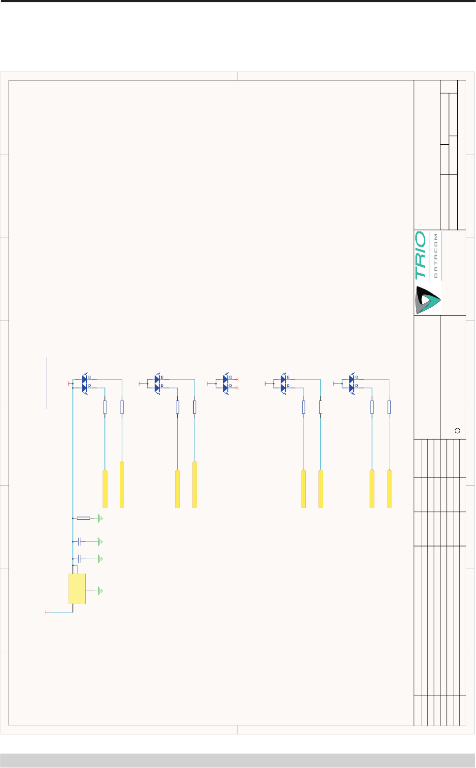
K-Series Status LEDs
D1
TITLE:
SIZE
A3
DATE:
SHT: OF
FILE:
CHKD:
DWG No.:
195-00-100-StatusLEDs.SchDoc
11-Jul-07
REV:
195-00-100
THIS DRAWING IS CONFIDENTIAL INFORMATION
Disclosure of this information, whether all or part thereof, cannot be
made to a 3rd party without the written consent of Trio Datacom
Pty. Ltd. Trio Datacom Pty. Ltd. reserves the right to change
documentation in the light of technical advancement.
COPYRIGHT
C
PCB No. REV.
DRN: P Hogan RG
Carrum Downs.
Victoria. Australia. 3201
A2
A3
A3
B2
C1
D1
B1
See Bugzilla Bug # Upissued to A2 and frozen
Upissued to A3
See Bugzilla Bug # 2696, 2748,2757, 2770,2819, 2872, 2876, 2877
Up issued to B1 and frozen.
Bugs 2990, 2993, 3001: R80-83,86-89=100R. NF parts fixed. Q6=NF.
PCB Rev C and schematic update. See ECN.
N/A
N/A
N/A
N/A
N/A
G. Rankin
G. Rankin
G. Rankin
G. Rankin
BWA
BWA
PAH
21/02/07
22/03/07
22/03/07
22/03/07
23/05/07
30/05/07
19/06/07PCB Rev D Schematic update see ECN sheet
195-01-100 D
STATUS LEDS
+3v3_LED
+3v3_LED
+3v3_LED
"Tx" = red, "Pwr" = green (default condition)
"RxSIG" = red, "Sync" = green
FROM RADIO MODULE
+3v3_LED
+3v3_LED
2007
"TxD" = red, "RxD" = green, BOTH "TX & RX" = amber
"TxD" = red, "RxD" = green, BOTH "TX & RX" = amber
MODULE-DC-POW-LED
MODULE-Rx-SYNC-LED
MODULE-Tx-LED
PORTB-TXD-LED
PORTA-TXD-LED
PORTA-RXD-LED
MODULE-RX-SIG-LED
PORTB-RXD-LED
R80
390R
R81
51R
R82
390R
R83
51R
R86
390R
R87
51R
R88
390R
R89
51R
R84
1K
+5V2
34
12
H1
KPBL-3025SURKMGKC
34
12
H2
KPBL-3025SURKMGKC
34
12
H3
NF (KPBL-3025SURKMGKC)
34
12
H4
KPBL-3025SURKMGKC
34
12
H5
KPBL-3025SURKMGKC
VIN
3
GND
1
VOUT 2
VOUT 4
Page 27
© Copyright 2008 Trio DataCom Pty. Ltd.
O Series Data Radio – User Manual
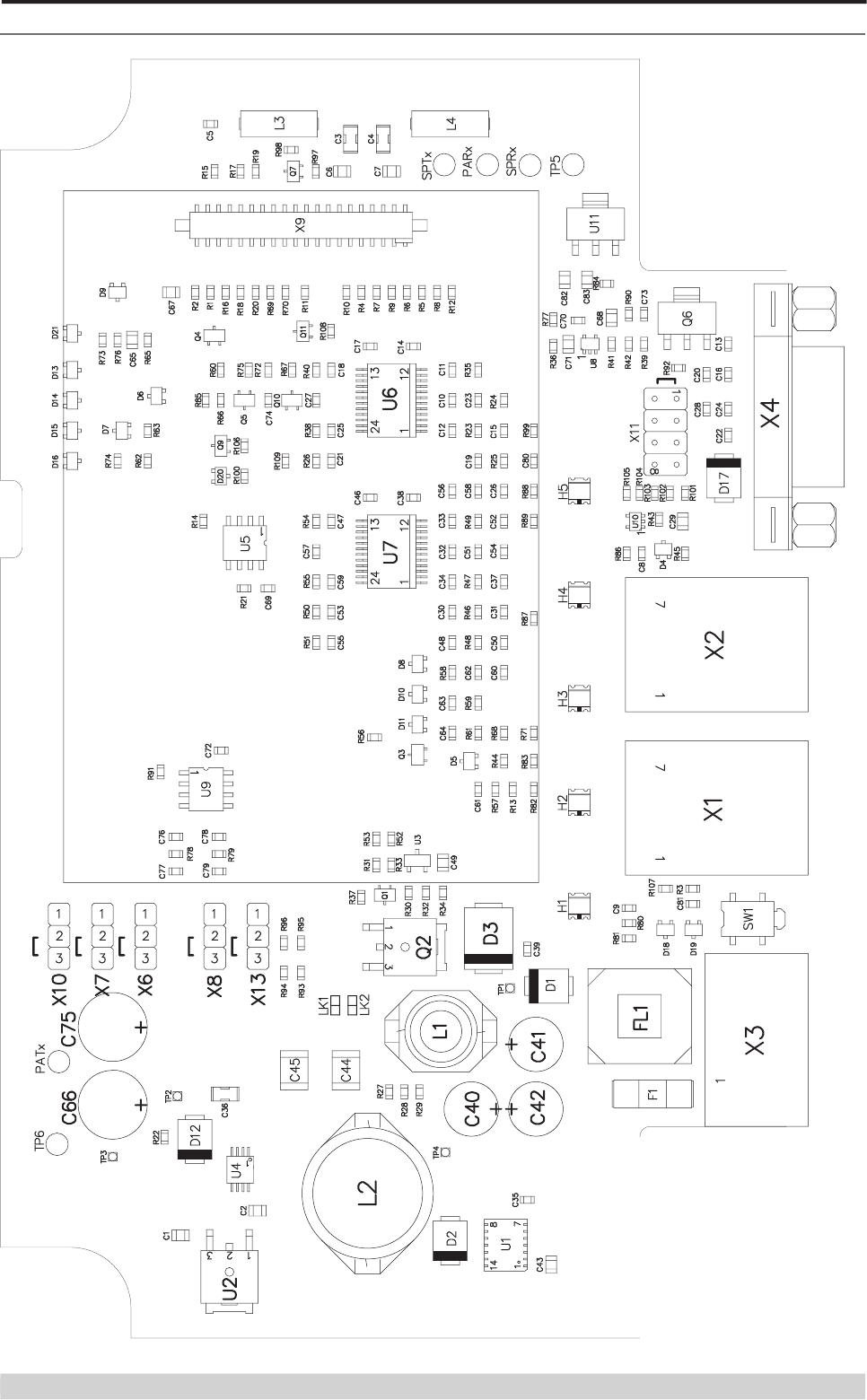
Overlay

Page 28
© Copyright 2008 Trio DataCom Pty. Ltd.
O Series Data Radio – User Manual
Parameter
900MHz Specifi cation
2.4GHz Specifi cation
Frequency Range
FCC: 902 – 928MHz, ACMA:
915-928MHz
2.4 - 2.4835MHz
Antenna Impedance:
50Ω
50Ω
Main Antenna Connector Type:
MMCX
MMCX
Auxiliary Antenna Connector Type:
MMCX
MMCX
Frequency Error (over temp range):
+/- 1.5ppm
+/- 3.0ppm
Supply Rails
DC Supply #1
5.0V ±5%
5.0V ±5%
DC Supply #2
3.3V ±5%
3.3V ±5%
Current Consumption (nom @ +25° C)
+10dBm output power
130mA@5v
240mA@3v3 & 117mA@5v
+20dBm output power
240mA@5v
360mA@3v3 & 275mA@5v
+27dBm output power
530mA@3v3 & 440mA@5v
+30dBm output power
820mA@5v
RX
<1mA @ 5.0V
270mA @3.3V
<1mA @ 5.0V
270mA @3.3V
Current Consumption (maximum)
+5.0v
1.35A
760mA
+3.3v
375mA
540mA
I/O Connector
Oupiin 2216-40-G-10-DPU
Oupiin 2216-40-G-10-DPU
Operating Temperature
-40 to +75°C
Duty cycle limits apply.
-40 to +75°C
Duty cycle limits apply.
Humidity
5 – 95% non-condensing
5 – 95% non-condensing
Storage Temperature
-40°C to +85°C
-40°C to +85°C
Dimensions
80mm x 55mm x 8mm (includ-
ing connectors)
80mm x 55mm x 8mm (includ-
ing connectors)
Modulation technique
2 Level GFSK
2 Level GFSK
Bandwidth
382kHz
382kHz
Part I – Specifi cations

Page 29
© Copyright 2008 Trio DataCom Pty. Ltd.
O Series Data Radio – User Manual
Part Number Description
Yagi Antennas
BMY890K
10dBd, 900MHz Yagi Directional Antenna
Bluewave, Marathon Series
BMY890G
6.5dBd, 900 MHz Yagi Directional Antenna
Bluewave, Marathon Series
BGY890K
10dBd, 900 MHz Yagi Directional Antenna
Bluewave, Gaurdian Series
BGY890G
6.5dBd, 900MHz Yagi Directional Antenna
Bluewave, Gaurdian Series
BXY24XI
6dBd, 2,4GHz Yagi Directional Antenna
Bluewave, Sentinel Series
BXY24XK
8dBd, 2,4GHz Yagi Directional Antenna
Bluewave, Sentinel Series
BXY24XM
10dBd, 2,4GHz Yagi Directional Antenna
Bluewave, Sentinel Series
Omni Antennas
BMO902J
9dBd, 900MHz Omni Directional Antenna
Bluewave, Marathon Series
BMO902H
7dBd, 900 MHz Omni Directional Antenna
Bluewave, Marathon Series
BMO902G
6dBd, 900 MHz Omni Directional Antenna
Bluewave, Marathon Series
BGO902G
6dBd, 900MHz Omni Directional Antenna
Bluewave, Gaurdian Series
BXO24XD
1dBd, 2.4GHz Omni Directional Antenna
Bluewave, Sentinel Series
BXO24XG
4dBd, 2.4GHz Omni Directional Antenna
Bluewave, Sentinel Series
BXO24XJ
7dBd, 2.4GHz Omni Directional Antenna
Bluewave, Sentinel Series
BXO24XM
10dBd, 2.4GHz Omni Directional Antenna
Bluewave, Sentinel Series
ANT2G4WHIP
0dBd, 2.4GHz Omni Directional Antenna Trio
Datacom, Whip Series
Panel Antennas
BXL24XM
10dBd, 2.4GHz Panel Directional Antenna
Bluewave, Sentinel Series
WARNING
Changes or modifi cations not expressly approved by Trio Datacom
could void the user’s authority to operate the equipment. Fixed
antennas require installation preventing end-users from replacing
them with non-approved antennas. Antennas not listed in the
above table must be tested to comply with FCC Section 15.203
(unique antenna connectors) and Section 15.247 (emissions).
Please contact Trio Datacom Inc. if you need more information.
Appendix – FCC Approved Antennas

Page 30
© Copyright 2008 Trio DataCom Pty. Ltd.
O Series Data Radio – User Manual
Innovative and sophisticated
digital communications
designs products and solutions
Information subject to change without notice.
© Copyright 2008 Trio DataCom Pty Ltd. All rights reserved.
Issue: 08-08
HEAD OFFICE
41 Aster Avenue,
Victoria, Australia 3201
Phone +61 3 8773 0100 Fax +61 3 9775 0505
sales@triodatacom.com
www.triodatacom.com
NORTH AMERICA
48 Steacie Drive, Kanata, ON Canada K2K 2A9
Tel: (613) 287 0786 Fax: (613) 591 1022
Toll Free: (866) 844 8746 (TRIO)
sales-na@triodatacom.com
www.triodatacom.com