Schneider Electric EER21000 Wiser Controller User Manual RC241x Data Sheet 1 1

Schneider Electric Wiser Controller RC241x Data Sheet 1 1

Contents

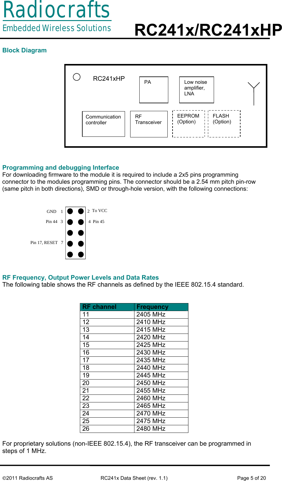
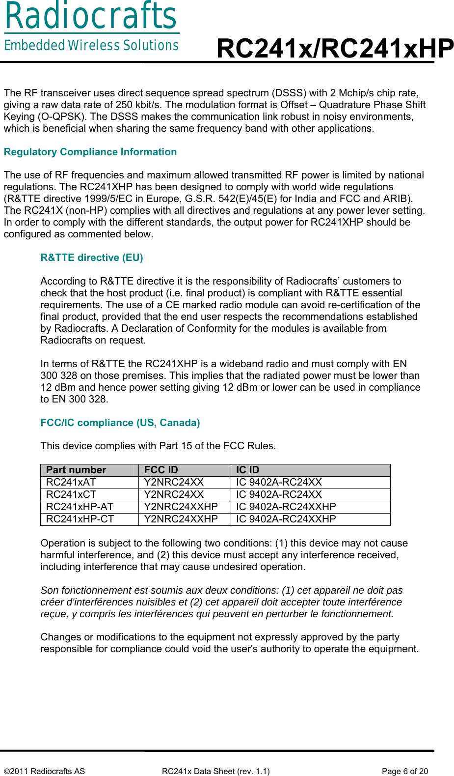
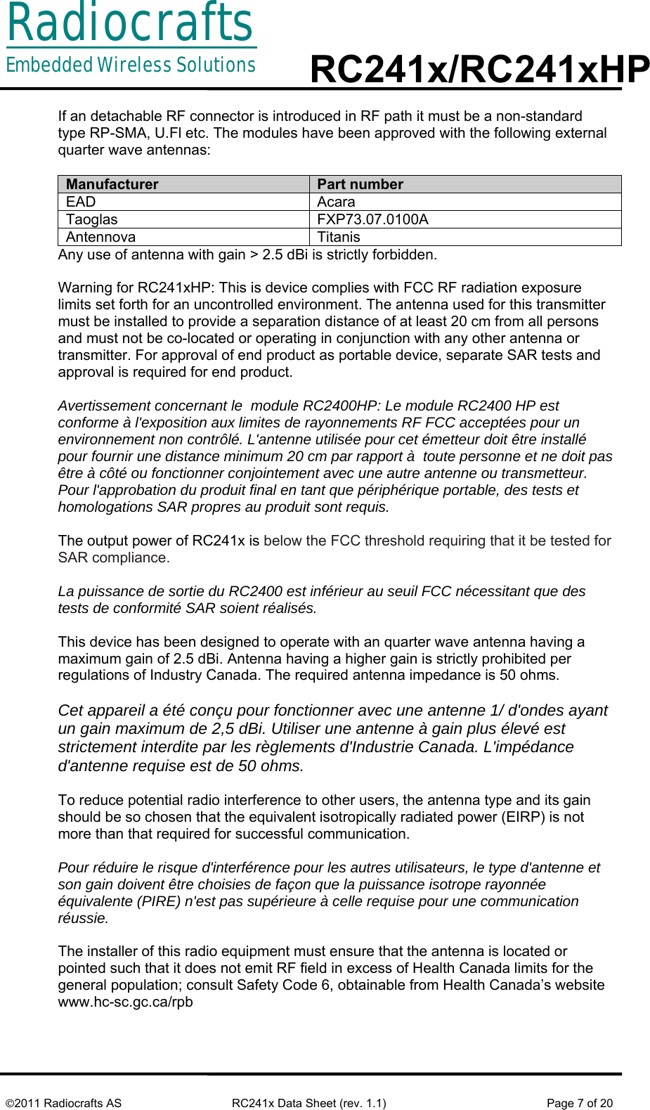
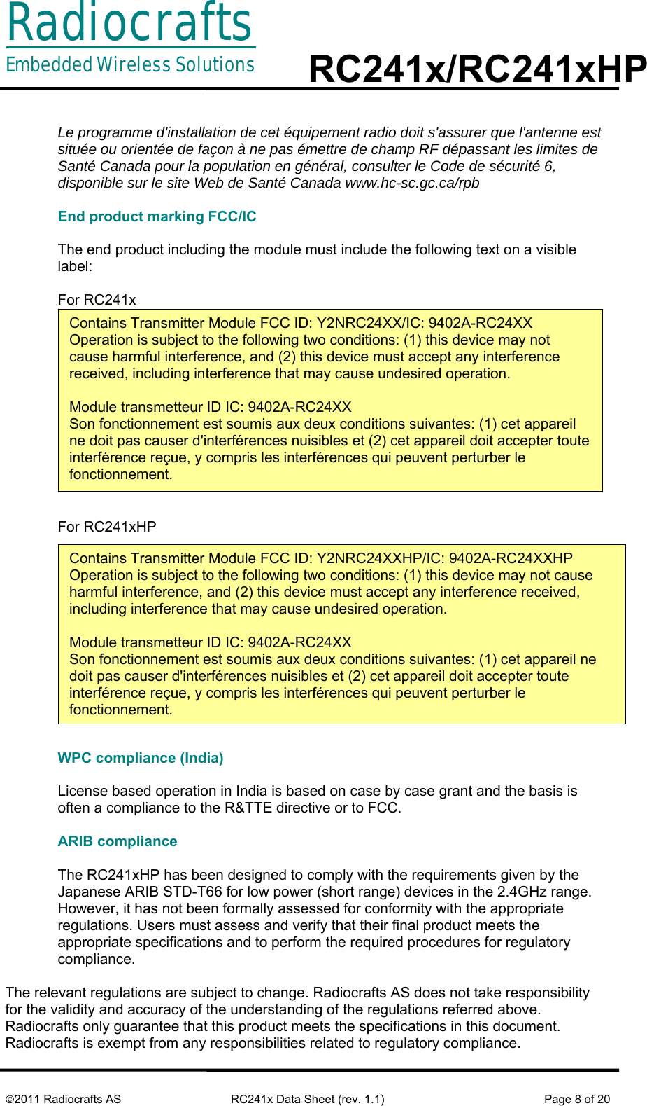
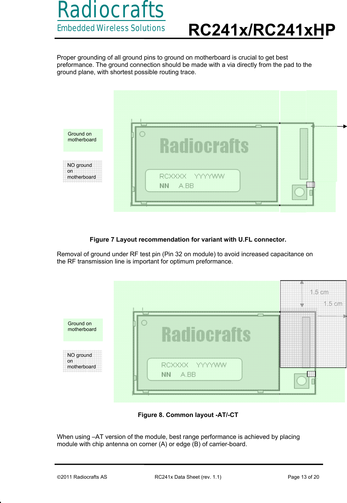
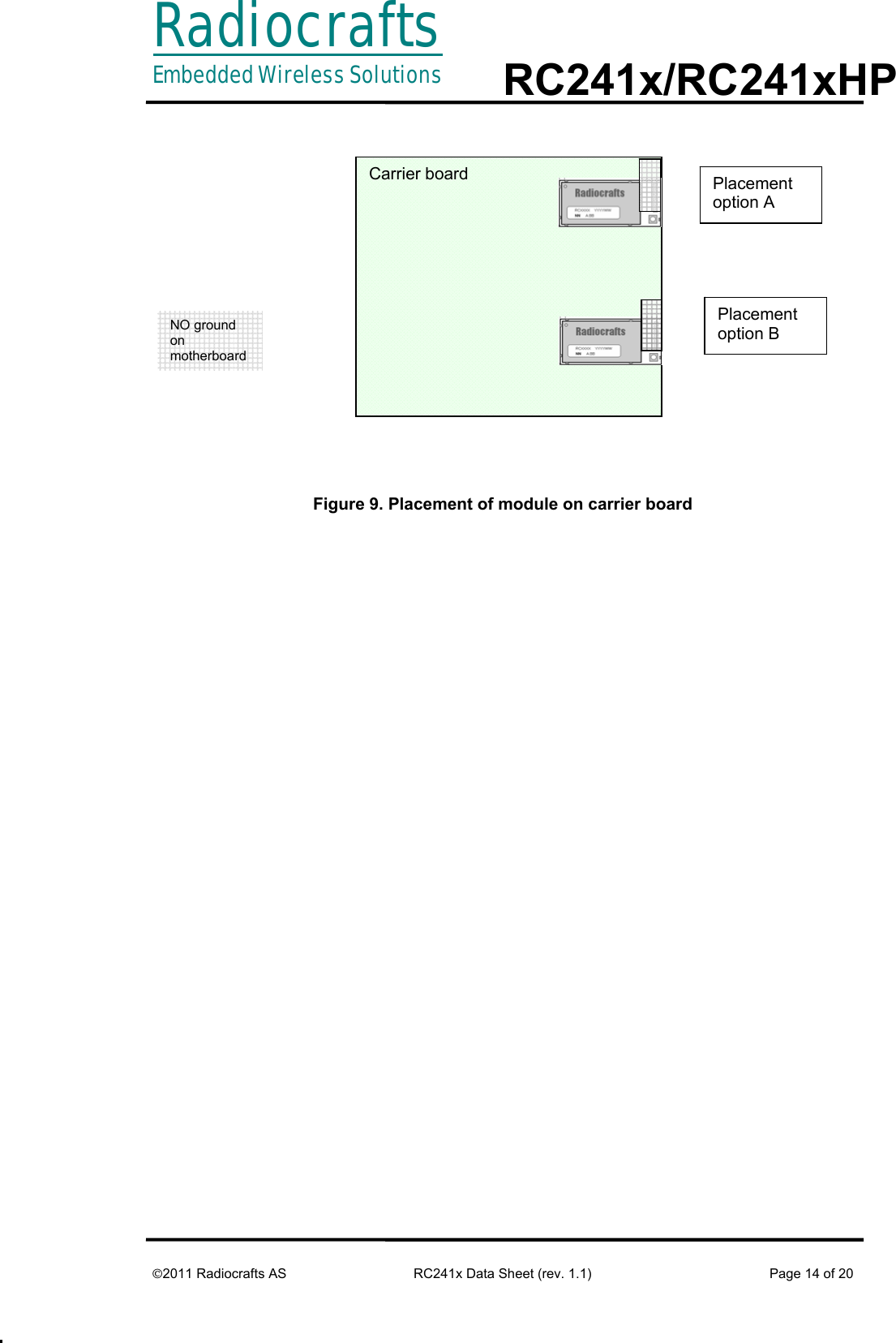
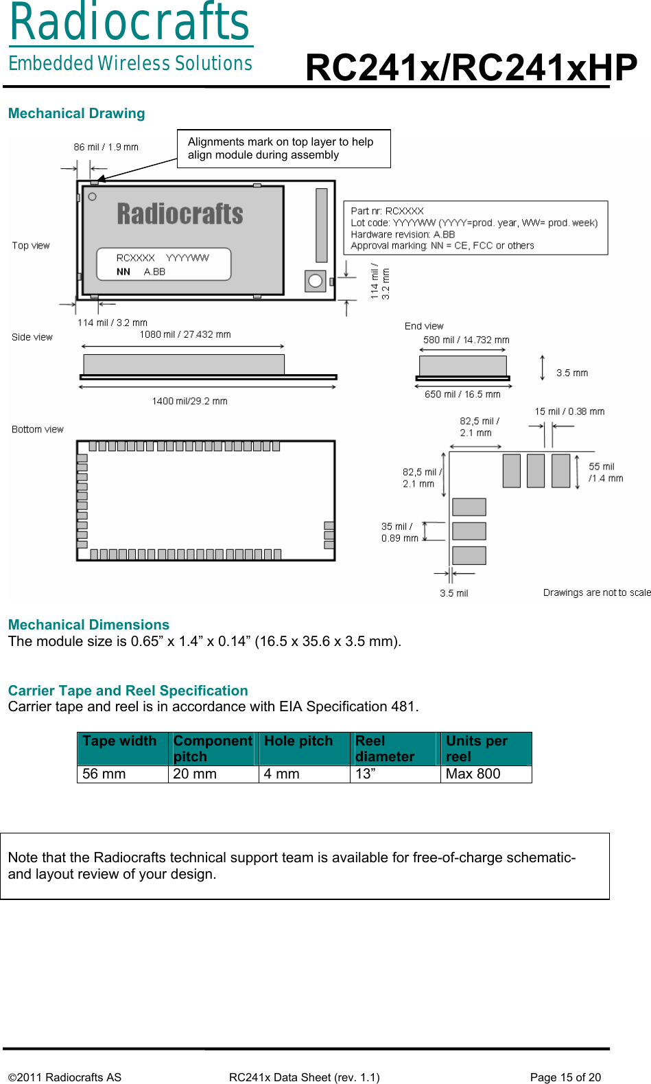
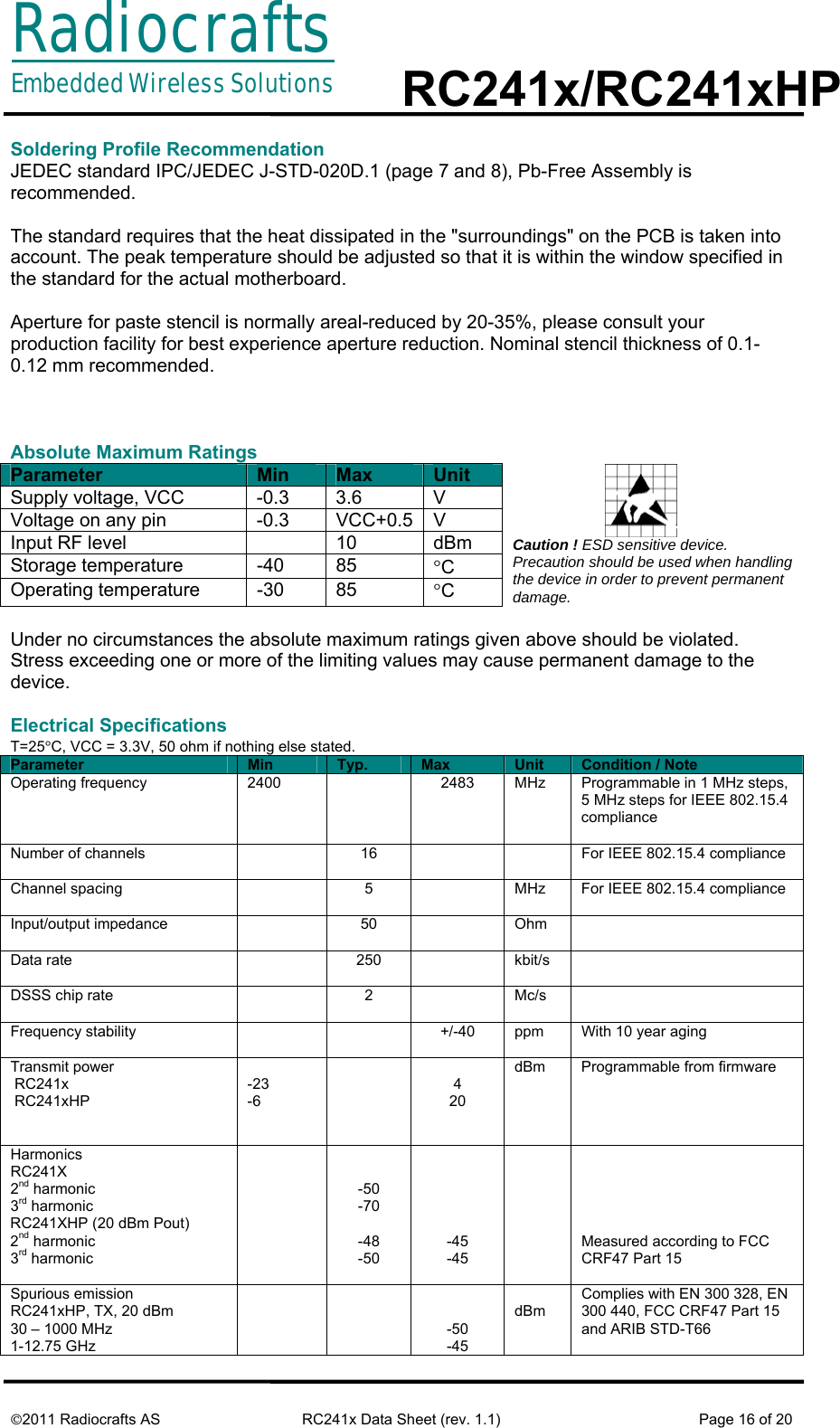
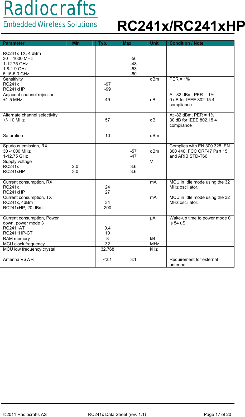
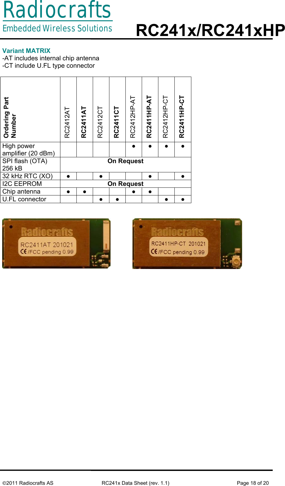
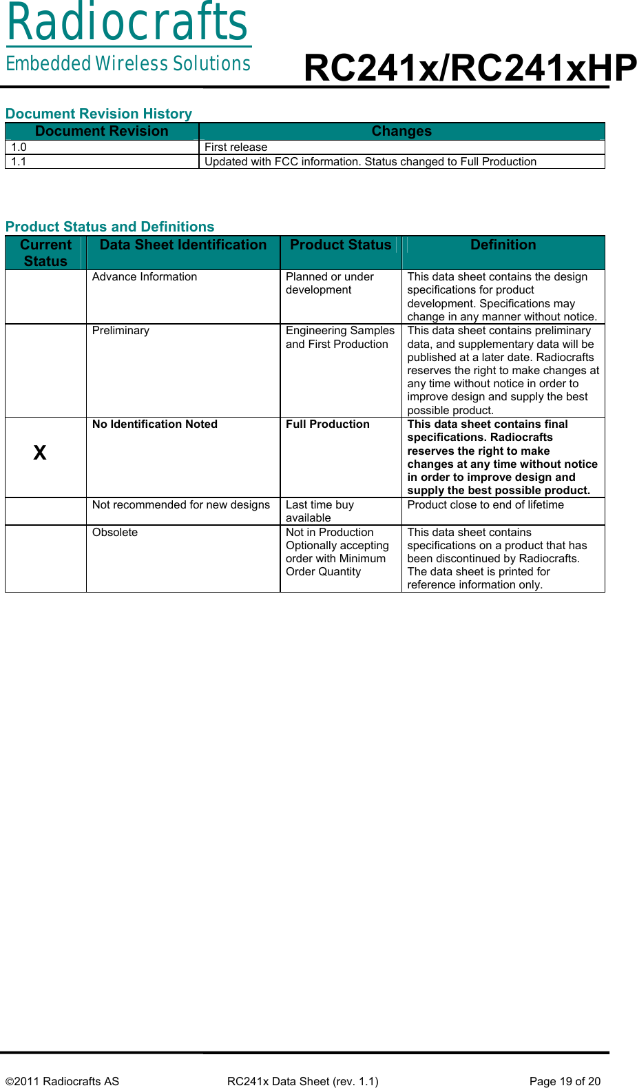
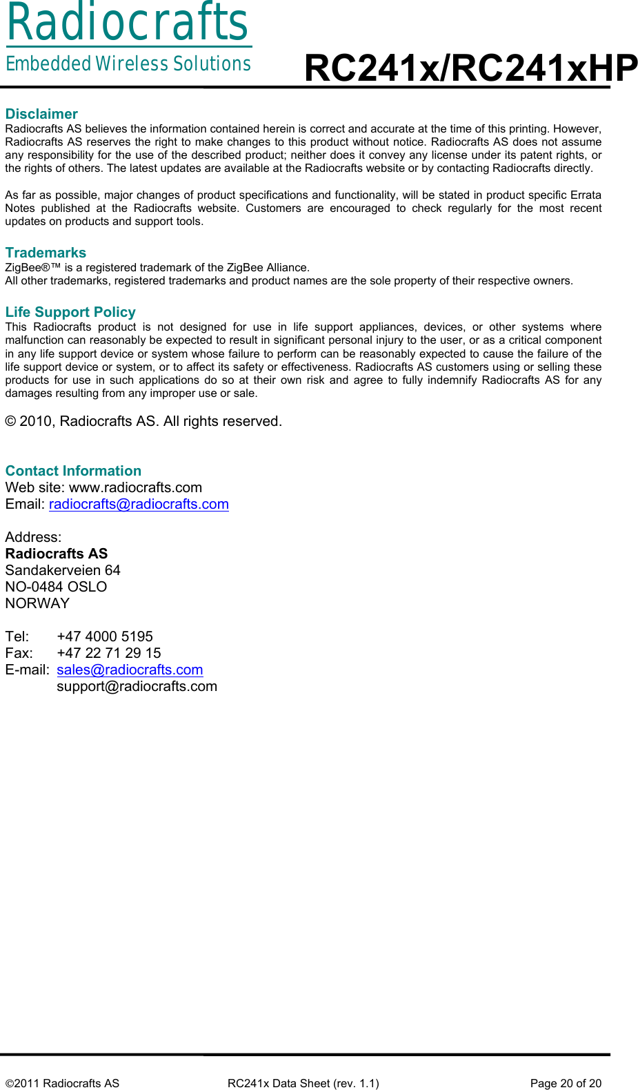
RF Module User Manual

RadiocraftsEmbedded Wireless Solutions  RC241x/RC241xHP     ©2011 Radiocrafts AS  RC241x Data Sheet (rev. 1.1)  Page 1 of 20  ZigBee®- Ready RF Transceiver Modules   Product Description The RC241x and RC241xHP RF Transceiver Modules are a series of compact surface-mounted modules specially designed for the ZigBee® PRO protocol stack. It can also be used for wireless star and mesh networks based on an IEEE 802.15.4 compliant PHY and MAC.   The complete shielded module is only 16.5 x 35.6 x 3.5 mm and comes in both a low-power consuming variant (RC241x) and a High Power version with LNA and power amplifier for extended range (RC241xHP). The two variants are pin compatible. The module is available with integrated antenna or RF connector (U.FL type)  Applications •  Home- and building automation •  Smart Metering / AMR / AMI •  Electricity, gas, water and heat meters •  Energy Service Portal (ESP) / Load Control •  IP sensor networks (6LoWPAN) •  Wireless sensor networks  Features •  100mW / 20 dBm option and low-power option in same packages •  16.5 x 35,6 x 3.5 mm compact shielded module for SMD mounting •  Integrated antenna option / U.FL connector option •  256 kB Flash memory, 8 kB SRAM •  15 digital and analogue I/Os, 8 channel 12 bit ADC •  2.0 – 3.6 V supply voltage, ultra low power modes •  Optional 4 kB internal EEPROM •  Optional internal SPI flash for over the air upgrade (OTA) •  Conforms with EN 300 440 and EN 300 328 (Europe), FCC CFR 47 part 15 (US),  ARIB STD-T66 (Japan) and G.S.R. 542(E)/45(E) (both for India)  Quick Reference Data (typical over manufacturing lots at 3.3V, frequency 2440 MHz) Parameter  RC241x  RC241xHP  Unit Frequency band  2.400-2.4835  GHz Number of channels  16   Data rate  250  kbit/s Max output power  4  20* dBm Sensitivity (PER 1%)  -97  -99  dBm Adjacent Channel Rejection  49  dB Alternate Channel Rejection  57  dB Supply voltage  2.0 - 3.6  3.0 - 3.6  Volt Current consumption, RX/TX  24/34  27/175  mA Current consumption, PD  0.4  10  uA Flash memory  256  kB RAM 8 kB Internal EEPROM (optional)  4  kB Operating Temperature   -30 to +85 (-40 to +85 available on request) °C                                                       * Limited to 12 dBm in Europe due to ETSI regulation and limited to 10 dBm in US for frequency 2480MHz due to FCC regulation.
RadiocraftsEmbedded Wireless Solutions  RC241x/RC241xHP     ©2011 Radiocrafts AS  RC241x Data Sheet (rev. 1.1)  Page 2 of 20  Quick Product Introduction The RC241x series of modules are specially designed to comply with IEEE 802.15.4-based industry standards like ZigBee PRO, 6LoWPAN, Wireless HART, RF4CE and others. Using the module together with the TI Z-stack is a powerful combination to build any ZigBee profile and application. The module contains qualified RF hardware and enough processor power to run the complete ZigBee mesh network protocol for a full function device including the application.   Using a pre-qualified module is the fastest way to make a ZigBee product and shortest time to market. The embedded RF HW and MCU resources in a 100% RF tested and pre-qualified module shorten the qualification and approval process. No RF design or RF expertise is required to add powerful wireless networking to the product. In most cases you only need supply voltage (for example an external battery) and a sensor/actuator and the module can run the entire application.  The module can be delivered as: •  RC241x/RC241xHP: HW platform. No preloaded firmware. •  RC2411x-ZNM/RC2411HP-ZNM : A complete ZigBee PRO network module where the entire ZigBee PRO compliant stack and configurable application software is preloaded in module and available via a serial API.  Article number and variants: -AT includes internal chip antenna -CT include U.FL type connector For detailed article numbers with various antenna variants, see page (18)  About this document This document is one part of the documentation for the module. It describes the electrical parameters, RF performance, footprint and PCB layout and regulatory information. Depending on the selected FW solution one additional User Manual should be used. See  •  RC24xx/RC24xxHP Firmware Development User Manual for using the module as a hardware platform only •  RC24xx/RC24xxHP-ZNM User Manual for details on how to use the ZNM module with preloaded ZigBee Pro stack and API through a serial interface.   Figure 1 Document structure RC241x/RC241xHP Datasheet (This document) RC24xx/RC24xxHP  Firmware Development User Manual RC24xx/RC24xxHP-ZNM User Manual Future  User Manuals
RadiocraftsEmbedded Wireless Solutions  RC241x/RC241xHP     ©2011 Radiocrafts AS  RC241x Data Sheet (rev. 1.1)  Page 3 of 20  Pin Assignment  Radiocrafts11011 30333153 34  Pin Description (See User Manual for more detailed pin out)  Pin no  Pin name  Description and internal MCU connection 1 GND  System ground 2  NC  Reserved for future use 3  NC  Reserved for future use 4 GND  System ground 5  I/O pin  Digital I/O 6  I/O pin  Digital I/O 7  I/O pin  Digital I/O 8  I/O pin  Digital I/O 9  I/O pin  Digital I/O 10 GND  System ground 11 GND  System ground 12  I/O pin  Digital I/O, HGM for PA CTRL IN HP VERSION 13  I/O pin  Digital I/O 14  I/O pin  Digital I/O 15  I/O pin  Digital I/O 16  I/O pin  Digital I/O ENABLE(LNA_ENABLE) FOR PA CTRL IN HP VERSION 17 RESET_N  RESET 18 NC  Not connected 19 NC  Not connected 20 NC  Not connected 21 NC  Not connected 22 NC  Not connected 23 NC  Not connected 24 NC  Not connected 25 NC  Not connected 26 NC  Not connected 27 NC  Not connected 28 NC  Not connected 29 NC  Not connected
RadiocraftsEmbedded Wireless Solutions  RC241x/RC241xHP     ©2011 Radiocrafts AS  RC241x Data Sheet (rev. 1.1)  Page 4 of 20  30 GND  System ground 31 GND  System ground 32  RF_TEST  RF I/O connection for Automatic test purposes. For modules intended for use with U.FL connector, do not connect this pad.   33 GND  System ground 34 GND  System ground 35 VCC  VCC 36 NC  Not connected 37 NC  Not connected 38 NC  Not connected 39 NC  Not connected 40 NC  Not connected 41  SPI_FLASH_RESET  RESET for SPI flash, NC for without SPI flash 42  I/O pin  Digital I/O or Connected to 32kHz crystal 43  I/O pin  Digital I/O or Connected to 32kHz crystal 44  I/O pin  Digital I/O or Programming 45  I/O pin  Digital I/O or Programming 46  I/O pin  Digital I/O 47  I/O pin  Digital I/O 48  I/O pin  Digital I/O 49  I/O pin  Digital I/O 50  I/O pin  Digital I/O 51  I/O, PA enable  Digital I/O, PA ENABLE FOR PA CTRL IN HP VERSION 52  I/O pin  Digital I/O 53 GND  System ground
RadiocraftsEmbedded Wireless Solutions  RC241x/RC241xHP     ©2011 Radiocrafts AS  RC241x Data Sheet (rev. 1.1)  Page 5 of 20  Block Diagram   Programming and debugging Interface For downloading firmware to the module it is required to include a 2x5 pins programming connector to the modules programming pins. The connector should be a 2.54 mm pitch pin-row (same pitch in both directions), SMD or through-hole version, with the following connections:      RF Frequency, Output Power Levels and Data Rates The following table shows the RF channels as defined by the IEEE 802.15.4 standard.   RF channel  Frequency 11 2405 MHz 12 2410 MHz 13 2415 MHz 14 2420 MHz 15 2425 MHz 16 2430 MHz 17 2435 MHz 18 2440 MHz 19 2445 MHz 20 2450 MHz 21 2455 MHz 22 2460 MHz 23 2465 MHz 24 2470 MHz 25 2475 MHz 26 2480 MHz  For proprietary solutions (non-IEEE 802.15.4), the RF transceiver can be programmed in steps of 1 MHz.    RC241xHP Communication controller  RF Transceiver  PA  Low noise amplifier, LNA EEPROM (Option)  GND    1  Pin 44   3 2To VCC4  Pin 45Pin 17, RESET   7   FLASH (Option)
RadiocraftsEmbedded Wireless Solutions  RC241x/RC241xHP     ©2011 Radiocrafts AS  RC241x Data Sheet (rev. 1.1)  Page 6 of 20   The RF transceiver uses direct sequence spread spectrum (DSSS) with 2 Mchip/s chip rate, giving a raw data rate of 250 kbit/s. The modulation format is Offset – Quadrature Phase Shift Keying (O-QPSK). The DSSS makes the communication link robust in noisy environments, which is beneficial when sharing the same frequency band with other applications.  Regulatory Compliance Information  The use of RF frequencies and maximum allowed transmitted RF power is limited by national regulations. The RC241XHP has been designed to comply with world wide regulations (R&TTE directive 1999/5/EC in Europe, G.S.R. 542(E)/45(E) for India and FCC and ARIB). The RC241X (non-HP) complies with all directives and regulations at any power lever setting. In order to comply with the different standards, the output power for RC241XHP should be configured as commented below.   R&TTE directive (EU)  According to R&TTE directive it is the responsibility of Radiocrafts’ customers to check that the host product (i.e. final product) is compliant with R&TTE essential requirements. The use of a CE marked radio module can avoid re-certification of the final product, provided that the end user respects the recommendations established by Radiocrafts. A Declaration of Conformity for the modules is available from Radiocrafts on request.  In terms of R&TTE the RC241XHP is a wideband radio and must comply with EN 300 328 on those premises. This implies that the radiated power must be lower than 12 dBm and hence power setting giving 12 dBm or lower can be used in compliance to EN 300 328.  FCC/IC compliance (US, Canada)   This device complies with Part 15 of the FCC Rules.  Part number  FCC ID  IC ID RC241xAT Y2NRC24XX IC 9402A-RC24XX RC241xCT Y2NRC24XX IC 9402A-RC24XX RC241xHP-AT Y2NRC24XXHP IC 9402A-RC24XXHP RC241xHP-CT Y2NRC24XXHP IC 9402A-RC24XXHP  Operation is subject to the following two conditions: (1) this device may not cause harmful interference, and (2) this device must accept any interference received, including interference that may cause undesired operation.  Son fonctionnement est soumis aux deux conditions: (1) cet appareil ne doit pas  créer d'interférences nuisibles et (2) cet appareil doit accepter toute interférence reçue, y compris les interférences qui peuvent en perturber le fonctionnement.  Changes or modifications to the equipment not expressly approved by the party responsible for compliance could void the user's authority to operate the equipment.
RadiocraftsEmbedded Wireless Solutions  RC241x/RC241xHP     ©2011 Radiocrafts AS  RC241x Data Sheet (rev. 1.1)  Page 7 of 20  If an detachable RF connector is introduced in RF path it must be a non-standard type RP-SMA, U.Fl etc. The modules have been approved with the following external quarter wave antennas:   Manufacturer  Part number EAD Acara Taoglas FXP73.07.0100A Antennova Titanis  Any use of antenna with gain > 2.5 dBi is strictly forbidden.  Warning for RC241xHP: This is device complies with FCC RF radiation exposure limits set forth for an uncontrolled environment. The antenna used for this transmitter must be installed to provide a separation distance of at least 20 cm from all persons and must not be co-located or operating in conjunction with any other antenna or transmitter. For approval of end product as portable device, separate SAR tests and approval is required for end product.  Avertissement concernant le  module RC2400HP: Le module RC2400 HP est conforme à l'exposition aux limites de rayonnements RF FCC acceptées pour un environnement non contrôlé. L'antenne utilisée pour cet émetteur doit être installé pour fournir une distance minimum 20 cm par rapport à  toute personne et ne doit pas être à côté ou fonctionner conjointement avec une autre antenne ou transmetteur. Pour l'approbation du produit final en tant que périphérique portable, des tests et homologations SAR propres au produit sont requis.  The output power of RC241x is below the FCC threshold requiring that it be tested for SAR compliance.  La puissance de sortie du RC2400 est inférieur au seuil FCC nécessitant que des tests de conformité SAR soient réalisés.  This device has been designed to operate with an quarter wave antenna having a maximum gain of 2.5 dBi. Antenna having a higher gain is strictly prohibited per regulations of Industry Canada. The required antenna impedance is 50 ohms.   Cet appareil a été conçu pour fonctionner avec une antenne 1/ d'ondes ayant un gain maximum de 2,5 dBi. Utiliser une antenne à gain plus élevé est strictement interdite par les règlements d'Industrie Canada. L'impédance d'antenne requise est de 50 ohms.  To reduce potential radio interference to other users, the antenna type and its gain should be so chosen that the equivalent isotropically radiated power (EIRP) is not more than that required for successful communication.   Pour réduire le risque d'interférence pour les autres utilisateurs, le type d'antenne et son gain doivent être choisies de façon que la puissance isotrope rayonnée équivalente (PIRE) n'est pas supérieure à celle requise pour une communication réussie.  The installer of this radio equipment must ensure that the antenna is located or pointed such that it does not emit RF field in excess of Health Canada limits for the general population; consult Safety Code 6, obtainable from Health Canada’s website www.hc-sc.gc.ca/rpb
RadiocraftsEmbedded Wireless Solutions  RC241x/RC241xHP     ©2011 Radiocrafts AS  RC241x Data Sheet (rev. 1.1)  Page 8 of 20   Le programme d'installation de cet équipement radio doit s'assurer que l'antenne est située ou orientée de façon à ne pas émettre de champ RF dépassant les limites de Santé Canada pour la population en général, consulter le Code de sécurité 6, disponible sur le site Web de Santé Canada www.hc-sc.gc.ca/rpb  End product marking FCC/IC  The end product including the module must include the following text on a visible label:   For RC241x   For RC241xHP     WPC compliance (India)     License based operation in India is based on case by case grant and the basis is   often a compliance to the R&TTE directive or to FCC.   ARIB compliance  The RC241xHP has been designed to comply with the requirements given by the Japanese ARIB STD-T66 for low power (short range) devices in the 2.4GHz range. However, it has not been formally assessed for conformity with the appropriate regulations. Users must assess and verify that their final product meets the appropriate specifications and to perform the required procedures for regulatory compliance.  The relevant regulations are subject to change. Radiocrafts AS does not take responsibility for the validity and accuracy of the understanding of the regulations referred above. Radiocrafts only guarantee that this product meets the specifications in this document. Radiocrafts is exempt from any responsibilities related to regulatory compliance. Contains Transmitter Module FCC ID: Y2NRC24XX/IC: 9402A-RC24XX Operation is subject to the following two conditions: (1) this device may not cause harmful interference, and (2) this device must accept any interference received, including interference that may cause undesired operation.  Module transmetteur ID IC: 9402A-RC24XX Son fonctionnement est soumis aux deux conditions suivantes: (1) cet appareil ne doit pas causer d'interférences nuisibles et (2) cet appareil doit accepter toute interférence reçue, y compris les interférences qui peuvent perturber le fonctionnement. Contains Transmitter Module FCC ID: Y2NRC24XXHP/IC: 9402A-RC24XXHP Operation is subject to the following two conditions: (1) this device may not cause harmful interference, and (2) this device must accept any interference received, including interference that may cause undesired operation.  Module transmetteur ID IC: 9402A-RC24XX Son fonctionnement est soumis aux deux conditions suivantes: (1) cet appareil ne doit pas causer d'interférences nuisibles et (2) cet appareil doit accepter toute interférence reçue, y compris les interférences qui peuvent perturber le fonctionnement.
RadiocraftsEmbedded Wireless Solutions  RC241x/RC241xHP     ©2011 Radiocrafts AS  RC241x Data Sheet (rev. 1.1)  Page 9 of 20  Antenna and Range Considerations The module needs an antenna to operate. The following antenna options could be considered.  Antenna  Advantage  Estimated LOS range (meters) RC241X Estimated  LOS range (meters) RC241XHP (100 mW) Chip antenna -AT  Low cost, easy to implement 200-300 1000-1500 External whip monopole High performance  500-700  3000-4000 External whip dipole High preformance, no large ground plane required 500-700 3000-4000  When using a module of -CT version with external antenna, the VSWR (Voltage Standing Wave Ratio) of the antenna should be less than 2:1. The VSWR is normally specified in the antenna datasheet and most commercial available antennas fulfil this requirement.  Also note that if the external antenna is a monopole connected with cable, the antenna require a ground plane at base of antenna. Only ground through the cable will not give optimal preformance for a monopole antenna.  Antenna parameter for a typical RC2411AT is shown below, for a module with equivalent 4 dBm conducted output power.  Parameter  Result   Total Radiated Power   -0,91 dBm Peak EIRP  1,83  dBm Directivity 2,74 dBi Efficiency -4,91 dB Efficiency 32,28494 % Gain -2,17 dBi
RadiocraftsEmbedded Wireless Solutions  RC241x/RC241xHP     ©2011 Radiocrafts AS  RC241x Data Sheet (rev. 1.1)  Page 10 of 20  Figure 2 Antenna radiation xy plane Figure 3. Antenna radiation yz plane Side view (looking into pin 34-53)  Side view (looking into pin 11-30) Top view Bottom view
RadiocraftsEmbedded Wireless Solutions  RC241x/RC241xHP     ©2011 Radiocrafts AS  RC241x Data Sheet (rev. 1.1)  Page 11 of 20  Figure 4. Antenna radiation xz plane   PCB Layout Recommendations The recommended layout pads for the module are shown in the figure below (top view, pin 1 is in upper left corner). All dimensions are in thousands of an inch (mil). The circle in upper left corner is an orientation mark only, and should not be a part of the copper pattern.  Front view, looking into antenna Rear view, looking into pin 1-10
RadiocraftsEmbedded Wireless Solutions  RC241x/RC241xHP     ©2011 Radiocrafts AS  RC241x Data Sheet (rev. 1.1)  Page 12 of 20   Figure 5 Recommended layout drawing with dimension (all numbers in mil)            Figure 6 Layout recommendation for variant with chip antenna (-AT) 1.5 cm1.5 cmGround on motherboard NO ground on motherboard mil
RadiocraftsEmbedded Wireless Solutions  RC241x/RC241xHP     ©2011 Radiocrafts AS  RC241x Data Sheet (rev. 1.1)  Page 13 of 20   Proper grounding of all ground pins to ground on motherboard is crucial to get best preformance. The ground connection should be made with a via directly from the pad to the ground plane, with shortest possible routing trace.      Figure 7 Layout recommendation for variant with U.FL connector.  Removal of ground under RF test pin (Pin 32 on module) to avoid increased capacitance on the RF transmission line is important for optimum preformance.     Figure 8. Common layout -AT/-CT   When using –AT version of the module, best range performance is achieved by placing module with chip antenna on corner (A) or edge (B) of carrier-board. 1.5 cm1.5 cmGround on motherboard NO ground on motherboard Ground on motherboard NO ground on motherboard
RadiocraftsEmbedded Wireless Solutions  RC241x/RC241xHP     ©2011 Radiocrafts AS  RC241x Data Sheet (rev. 1.1)  Page 14 of 20    Figure 9. Placement of module on carrier board   NO ground on motherboard Placement option A Placement option B Carrier board
RadiocraftsEmbedded Wireless Solutions  RC241x/RC241xHP     ©2011 Radiocrafts AS  RC241x Data Sheet (rev. 1.1)  Page 15 of 20  Mechanical Drawing    Mechanical Dimensions The module size is 0.65” x 1.4” x 0.14” (16.5 x 35.6 x 3.5 mm).   Carrier Tape and Reel Specification Carrier tape and reel is in accordance with EIA Specification 481.  Tape width  Component pitch Hole pitch  Reel diameter Units per reel 56 mm  20 mm  4 mm  13”  Max 800     Note that the Radiocrafts technical support team is available for free-of-charge schematic- and layout review of your design.       Alignments mark on top layer to help  align module during assembly
RadiocraftsEmbedded Wireless Solutions  RC241x/RC241xHP     ©2011 Radiocrafts AS  RC241x Data Sheet (rev. 1.1)  Page 16 of 20  Soldering Profile Recommendation JEDEC standard IPC/JEDEC J-STD-020D.1 (page 7 and 8), Pb-Free Assembly is recommended.  The standard requires that the heat dissipated in the "surroundings" on the PCB is taken into account. The peak temperature should be adjusted so that it is within the window specified in the standard for the actual motherboard.  Aperture for paste stencil is normally areal-reduced by 20-35%, please consult your production facility for best experience aperture reduction. Nominal stencil thickness of 0.1-0.12 mm recommended.     Absolute Maximum Ratings Parameter  Min  Max  Unit Supply voltage, VCC  -0.3  3.6  V Voltage on any pin  -0.3  VCC+0.5 V Input RF level    10  dBm Storage temperature  -40  85  °C Operating temperature  -30  85  °C                         Caution ! ESD sensitive device. Precaution should be used when handling the device in order to prevent permanent damage.  Under no circumstances the absolute maximum ratings given above should be violated. Stress exceeding one or more of the limiting values may cause permanent damage to the device.  Electrical Specifications T=25°C, VCC = 3.3V, 50 ohm if nothing else stated. Parameter  Min  Typ.  Max  Unit  Condition / Note Operating frequency  2400    2483  MHz  Programmable in 1 MHz steps, 5 MHz steps for IEEE 802.15.4 compliance  Number of channels    16      For IEEE 802.15.4 compliance Channel spacing    5    MHz  For IEEE 802.15.4 compliance Input/output impedance   50  Ohm  Data rate   250  kbit/s  DSSS chip rate   2  Mc/s  Frequency stability      +/-40  ppm  With 10 year aging Transmit power   RC241x  RC241xHP    -23 -6   4 20 dBm  Programmable from firmware Harmonics RC241X  2nd harmonic 3rd harmonic RC241XHP (20 dBm Pout) 2nd harmonic  3rd harmonic     -50 -70  -48 -50      -45 -45       Measured according to FCC CRF47 Part 15 Spurious emission RC241xHP, TX, 20 dBm 30 – 1000 MHz  1-12.75 GHz      -50 -45  dBm Complies with EN 300 328, EN 300 440, FCC CRF47 Part 15 and ARIB STD-T66
RadiocraftsEmbedded Wireless Solutions  RC241x/RC241xHP     ©2011 Radiocrafts AS  RC241x Data Sheet (rev. 1.1)  Page 17 of 20  Parameter  Min  Typ.  Max  Unit  Condition / Note  RC241x TX, 4 dBm 30 – 1000 MHz 1-12.75 GHz 1.8-1.9 GHz 5.15-5.3 GHz   -56 -48 -53 -60 Sensitivity RC241x RC241xHP   -97 -99   dBm  PER = 1% Adjacent channel rejection +/- 5 MHz    49   dB At -82 dBm, PER = 1%. 0 dB for IEEE 802.15.4 compliance  Alternate channel selectivity +/- 10 MHz   57    dB At -82 dBm, PER = 1%. 30 dB for IEEE 802.15.4 compliance  Saturation   10  dBm  Spurious emission, RX 30 -1000 MHz 1-12.75 GHz    -57 -47  dBm Complies with EN 300 328, EN 300 440, FCC CRF47 Part 15 and ARIB STD-T66 Supply voltage RC241x RC241xHP   2.0 3.0   3.6 3.6 V  Current consumption, RX RC241x RC241xHP   24 27   mA  MCU in Idle mode using the 32 MHz oscillator. Current consumption, TX RC241x, 4dBm RC241xHP, 20 dBm   34 200    mA  MCU in Idle mode using the 32 MHz oscillator. Current consumption, Power down, power mode 3 RC2411AT RC2411HP-CT    0.4 10  µA  Wake-up time to power mode 0 is 54 uS  RAM memory    8   kB  MCU clock frequency    32   MHz  MCU low frequency crystal   32.768  kHz  Antenna VSWR    <2:1  3:1    Requirement for external antenna
RadiocraftsEmbedded Wireless Solutions  RC241x/RC241xHP     ©2011 Radiocrafts AS  RC241x Data Sheet (rev. 1.1)  Page 18 of 20  Variant MATRIX -AT includes internal chip antenna -CT include U.FL type connector  Ordering Part  Number RC2412AT RC2411AT  RC2412CT RC2411CT RC2412HP-AT RC2411HP-AT RC2412HP-CT RC2411HP-CT High power amplifier (20 dBm)     ● ● ● ● SPI flash (OTA) 256 kB On Request 32 kHz RTC (XO)  ●  ●   ●  ● I2C EEPROM   On Request Chip antenna  ● ●   ● ●   U.FL connector     ● ●   ● ●
RadiocraftsEmbedded Wireless Solutions  RC241x/RC241xHP     ©2011 Radiocrafts AS  RC241x Data Sheet (rev. 1.1)  Page 19 of 20  Document Revision History Document Revision  Changes 1.0 First release 1.1  Updated with FCC information. Status changed to Full Production    Product Status and Definitions Current Status Data Sheet Identification  Product Status  Definition         Advance Information  Planned or under development This data sheet contains the design specifications for product development. Specifications may change in any manner without notice.      Preliminary Engineering Samples and First Production This data sheet contains preliminary data, and supplementary data will be published at a later date. Radiocrafts reserves the right to make changes at any time without notice in order to improve design and supply the best possible product.          X No Identification Noted  Full Production  This data sheet contains final specifications. Radiocrafts reserves the right to make changes at any time without notice in order to improve design and supply the best possible product.  Not recommended for new designs  Last time buy available Product close to end of lifetime   Obsolete  Not in Production Optionally accepting order with Minimum Order Quantity This data sheet contains specifications on a product that has been discontinued by Radiocrafts. The data sheet is printed for reference information only.
RadiocraftsEmbedded Wireless Solutions  RC241x/RC241xHP     ©2011 Radiocrafts AS  RC241x Data Sheet (rev. 1.1)  Page 20 of 20  Disclaimer Radiocrafts AS believes the information contained herein is correct and accurate at the time of this printing. However, Radiocrafts AS reserves the right to make changes to this product without notice. Radiocrafts AS does not assume any responsibility for the use of the described product; neither does it convey any license under its patent rights, or the rights of others. The latest updates are available at the Radiocrafts website or by contacting Radiocrafts directly.  As far as possible, major changes of product specifications and functionality, will be stated in product specific Errata Notes published at the Radiocrafts website. Customers are encouraged to check regularly for the most recent updates on products and support tools.  Trademarks ZigBee®™ is a registered trademark of the ZigBee Alliance.  All other trademarks, registered trademarks and product names are the sole property of their respective owners.  Life Support Policy This Radiocrafts product is not designed for use in life support appliances, devices, or other systems where malfunction can reasonably be expected to result in significant personal injury to the user, or as a critical component in any life support device or system whose failure to perform can be reasonably expected to cause the failure of the life support device or system, or to affect its safety or effectiveness. Radiocrafts AS customers using or selling these products for use in such applications do so at their own risk and agree to fully indemnify Radiocrafts AS for any damages resulting from any improper use or sale.  © 2010, Radiocrafts AS. All rights reserved.   Contact Information Web site: www.radiocrafts.com Email: radiocrafts@radiocrafts.com  Address: Radiocrafts AS Sandakerveien 64 NO-0484 OSLO NORWAY  Tel:   +47 4000 5195 Fax:   +47 22 71 29 15 E-mail:  sales@radiocrafts.com support@radiocrafts.com

Navigation menu