Schneider Electric S1B15258 USB Zigbee Interface User Manual Manual
Schneider Electric (Australia) Pty. Ltd. USB Zigbee Interface Manual
UserManual.wiki
>
Schneider Electric
>
S1B15258 User Manual
Manual
Navigation menu
Upload a User Manual
Namespaces
Wiki Guide
HTML
PDF
Info
Views
User Manual
Discussion / Help
Navigation
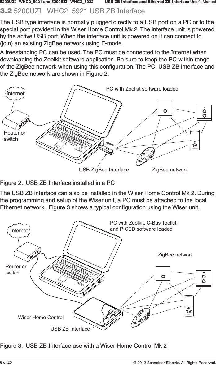
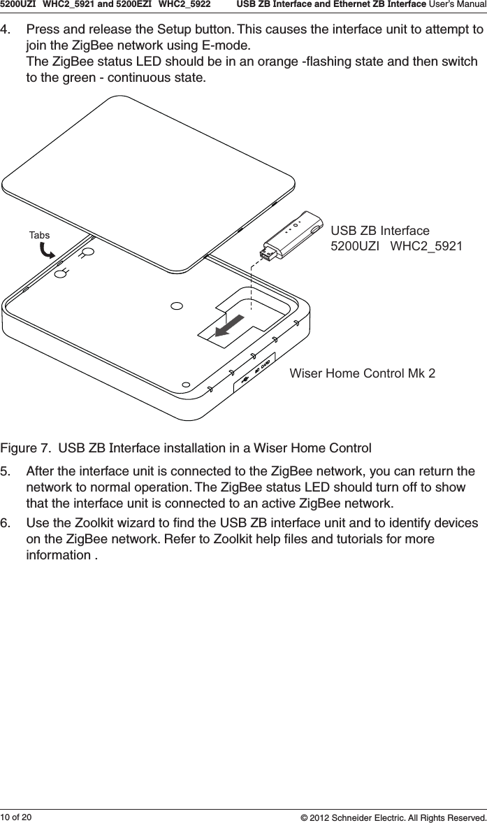
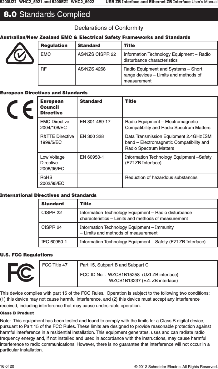
![17 of 205200UZI WHC2_5921 and 5200EZI WHC2_5922 USB ZB Interface and Ethernet ZB Interface User’s Manual© 2012 Schneider Electric. All Rights Reserved.If this equipment does cause harmful interference to radio or television reception, which can be determined by turning the equipment off and on, the user is encouraged to try to correct the interference by one or more of the following measures:•Reorientorrelocatethereceivingantenna. •Increasetheseparationbetweentheequipmentandreceiver. •Connecttheequipmentintoanoutletonacircuitdifferentfromthattowhichthereceiverisconnected. •Consultthedealeroranexperiencedradio/TVtechnicianforhelp.Subpart C Intentional, Unintentional and Incidental RadiatorOperation of an intentional, unintentional, or incidental radiator is subject to the conditions that no harmful interference is caused and that interference must be accepted that may be caused by the operation of an authorized [licensed] radio station, by another intentional or unintentional radiator, by industrial, scientific and medical (ISM) equipment, or by an incidental radiator.Singapore (IDA)Complies with IDA standards: DA104328 (UZI ZB Interface) Pending (EZI ZB Interface)China (SRRC)CMIIT ID number: Pending (UZI ZB Interface) Pending (EZI ZB Interface)ZigBee AllianceZigBee Certified Product – Home Automation profileDo not dispose of this product to landfill or by incineration. This productshould be disposed of by a licenced electronic waste disposal agency. In some locations it is an offense to dispose of electronic items improperly.Warning:Any changes or modifications not expressly approved by Clipsal Integrated Systems or Schneider Electric could void the user’s authority to operate this equipment.](https://usermanual.wiki/Schneider-Electric/S1B15258/User-Guide-1815216-Page-17.png)