Schneider Electric S1B15258 USB Zigbee Interface User Manual Manual
Schneider Electric (Australia) Pty. Ltd. USB Zigbee Interface Manual
Manual
USB ZB Interface Unit
Ethernet ZB Interface Unit
5200UZI WHC2_5921
5200EZI WHC2_5922
User’s Manual

5200UZI WHC2_5921 and 5200EZI WHC2_5922 USB ZB Interface and Ethernet ZB Interface User’s Manual
© 2012 Schneider Electric. All Rights Reserved.
Contents
1.0 Package Components ...................................................................................3
2.0 Safety and Product Handling Instructions ..................................................4
3.0 Introduction ....................................................................................................5
3.1 What is a ZigBee Network? ......................................................................5
3.2 5200UZI WHC2_5921 USB ZB Interface ...............................................6
3.3 5200EZI WHC2_5922 Ethernet ZB Interface .........................................7
4.0 Switch Buttons and Indicators .....................................................................8
5.0 Installation .....................................................................................................9
5.1 USB ZB Interface ...................................................................................... 9
5.2 Ethernet ZB Interface .............................................................................11
6.0 Commissioning and Troubleshooting ........................................................12
6.1 Troubleshooting .......................................................................................12
6.2 Reset Button ...........................................................................................13
7.0 Specifications ..............................................................................................14
7.1 USB ZB Interface .................................................................................... 14
7.2 Ethernet ZB Interface .............................................................................15
8.0 Standards Complied ....................................................................................16
9.0 Installation Notes ........................................................................................18
9.0 Two-Year Warranty .......................................................................................19
ZigBee and the ZigBee logo are registered trademarks of the ZigBee Alliance.
Wiser Home Control, Wiser Home Control 2, Clipsal and C-Bus are registered trademarks of Schneider
Electric Industries SAS.
All other trademarks are the property of their respective owners.
© 2012 Schneider Electric. All Rights Reserved.
Schneider Electric reserves the right to change specifications, modify designs and discontinue items
without incurring obligation. While every effort is made to ensure that descriptions, specifictions and other
information in this user manual are correct, no warranty is given in respect thereof and the company shall
not be liable for any error therein.
3 of 20
5200UZI WHC2_5921 and 5200EZI WHC2_5922 USB ZB Interface and Ethernet ZB Interface User’s Manual
© 2012 Schneider Electric. All Rights Reserved.
1.0 Package Components
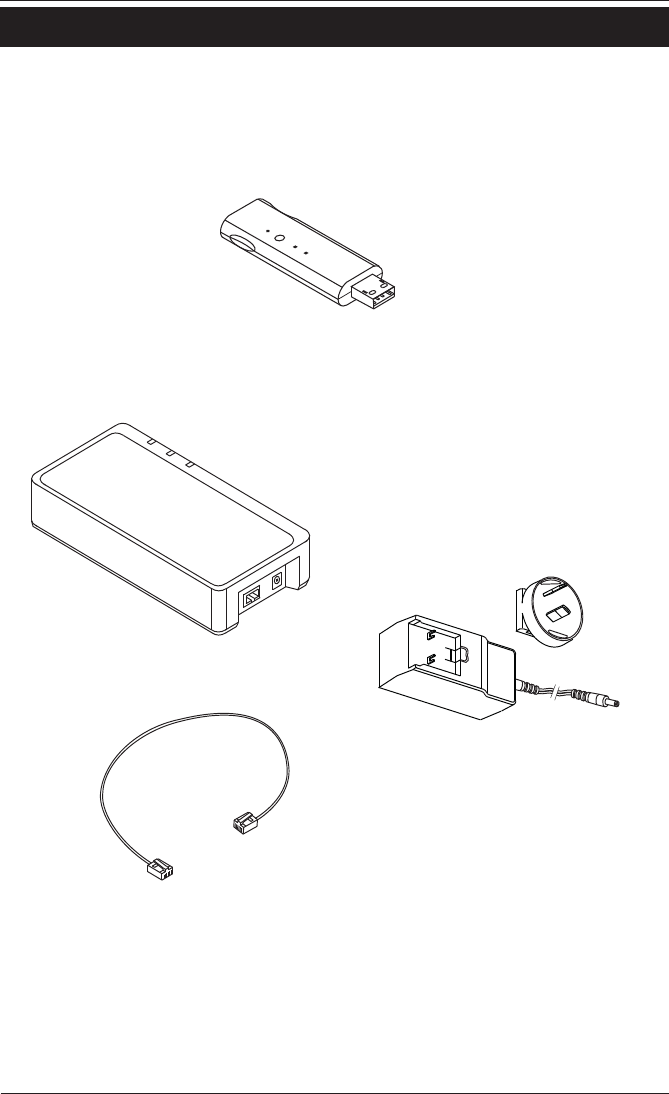
The package components for the USB ZB Interface Unit and the Ethernet ZB
Interface Unit are shown below.
5200UZI WHC2_5921 USB ZB Interface Unit
5200EZI WHC2_5922 Ethernet ZB Interface Unit
5200EZI WHC2-5922
Power supply and AC Adapter
for Australia and New Zealand
Category 5e Network Cable
Figure 1. Package Components
Note:
In this document, ZB stands for ZigBee which is a registered
trademark of the ZigBee Alliance.

4 of 20
5200UZI WHC2_5921 and 5200EZI WHC2_5922 USB ZB Interface and Ethernet ZB Interface User’s Manual
© 2012 Schneider Electric. All Rights Reserved.
2.0 Safety and Product Handling Instructions
The ZigBee Interface units are for indoor use only. The units are designed for
use with a PC or with a Wiser Home Control. Please read and follow these safety
Cautions and Warnings.
Warning. Automatic Control Device
Equipment controlled by this device may start or stop at any time without
warning. Do not make wiring changes or adjustments to connected
appliances or lights without first disconnecting building power.
Warning. Not Intended for Medical Applications
Do not use this equipment for any application that is critical to the health
or life of any person. Do not place this equipment close to networked
medical devices, such as heart monitors.
Follow these guidelines to prevent damage to the interface unit:
• Do not attempt to disassemble the interface unit. There are no user serviceable
parts inside.
• Do not allow the unit to get wet.
• Do not allow metal objects to contact the pins inside the USB or Ethernet
connector.
• Keep the unit away from dust, direct sunlight, heat and moisture.
• Do not force the USB interface unit into the USB slot.
• Do not allow children to play with the unit.
When operating the interface units keep the following in mind:
• Pressing and holding the USB interface’s reset button or the Ethernet interface
unit’s SETUP button erases the current ZigBee configuration.
• Do not disconnect or remove power from the unit when the orange light is
flashing rapidly(a firmware load is in progress).

5 of 20
5200UZI WHC2_5921 and 5200EZI WHC2_5922 USB ZB Interface and Ethernet ZB Interface User’s Manual
© 2012 Schneider Electric. All Rights Reserved.
3.0 Introduction
The ZB interface unit provides a wireless connection between a PC and an existing
ZigBee network. The interface unit has the following capabilities:
• The ZB interface unit can connect to an existing ZigBee network using E-mode
(easy mode).
• When connected to a PC with Zoolkit configuration software loaded, the ZB
interface unit lets you retrieve the ZigBee configuration and create a file to be
used by PICED and the Wiser Home Control Mk2.
• Using Zoolkit and the interface unit, you can view and control the devices on the
ZigBee network.
The applicable software programs used with the interface unit include: Zoolkit, IP
Utility, C-Bus Toolkit and PICED software programs. The software programs can be
downloaded from the Clipsal CIS web site:
http://www.clipsal.com/cis/ On the Technical page, select Downloads.
3.1 What is a ZigBee Network?
ZigBee is a wireless control system protocol that manages the operation devices on
the network. Some of the advantages of a ZigBee network are as follows:
• You can set up devices such as switches or sensors to turn lights on or off, open
or close curtains, and operate a range of other ZigBee devices.
• A major advantage of the ZigBee control system is that the signals can travel
through solid objects and walls.
• ZigBee devices generally use very little power and are easily installed and
programmed.
• You can have multiple ZigBee networks in the same area without problems.
ZigBee device compatibility is strictly maintained by the ZigBee Alliance. All devices
are required to conform to strict requirements to be certified for use in ZigBee
networks.
Note: The effective range of ZigBee control signals is approximately 20 metres.
However, this can be affected by the type of walls and solid objects between the
devices and and the proximity of devices to sources of electrical interference. In
your installation, you might have to adjust the location of devices to obtain the best
results.
6 of 20
5200UZI WHC2_5921 and 5200EZI WHC2_5922 USB ZB Interface and Ethernet ZB Interface User’s Manual
© 2012 Schneider Electric. All Rights Reserved.
3.2 5200UZI WHC2_5921 USB ZB Interface
The USB type interface is normally plugged directly to a USB port on a PC or to the
special port provided in the Wiser Home Control Mk 2. The interface unit is powered
by the active USB port. When the interface unit is powered on it can connect to
(join) an existing ZigBee network using E-mode.
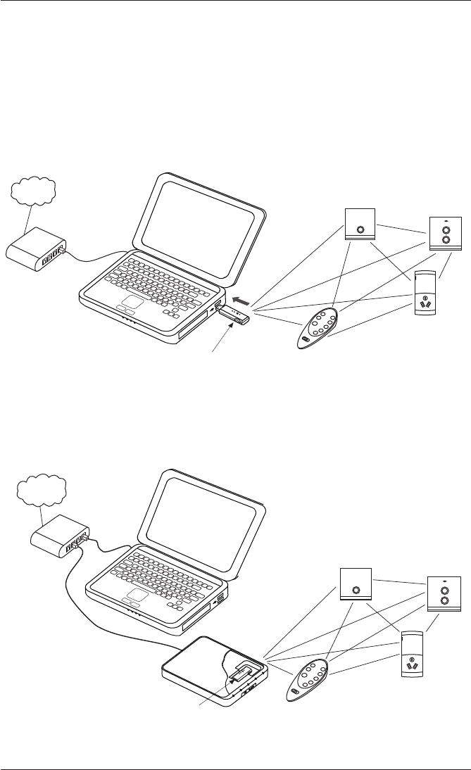
A freestanding PC can be used. The PC must be connected to the Internet when
downloading the Zoolkit software application. Be sure to keep the PC within range
of the ZigBee network when using this configuration. The PC, USB ZB interface and
the ZigBee network are shown in Figure 2.
Figure 2. USB ZB Interface installed in a PC
The USB ZB interface can also be installed in the Wiser Home Control Mk 2. During
the programming and setup of the Wiser unit, a PC must be attached to the local
Ethernet network. Figure 3 shows a typical configuration using the Wiser unit.
Internet
PC with Zoolkit, C-Bus Toolkit
and PICED software loaded
Router or
switch
Wiser Home Control
USB ZB Interface
ZigBee network
Figure 3. USB ZB Interface use with a Wiser Home Control Mk 2
PC with Zoolkit software loaded
Internet
Router or
switch
USB ZigBee Interface ZigBee network
7 of 20
5200UZI WHC2_5921 and 5200EZI WHC2_5922 USB ZB Interface and Ethernet ZB Interface User’s Manual
© 2012 Schneider Electric. All Rights Reserved.
3.3 5200EZI WHC2_5922 Ethernet USB Interface
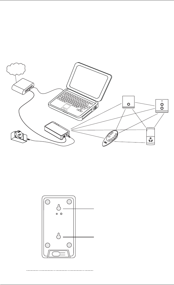
The Ethernet ZB interface is connected to a router or switch on the local Ethernet
network. A network patch cable is provided with the unit. Use only the supplied
AC power supply to power the unit. The PC that has Zoolkit software loaded is
connected to the same network (VLAN) as the interface unit. The Control Systems
IP Utility configures IP address for the Ethernet ZB unit on the local network
(VLAN). The interface unit can connect to an available ZigBee network using
E-mode. A typical Ethernet ZB interface installation is shown in Figure 4.
PC with Zoolkit software loaded
Internet
Router or
switch
Ethernet
ZigBee Interface
ZigBee network
Figure 4. Ethernet ZB Interface connected to the local network
The Ethernet ZB interface unit can be installed in a horizontal or vertical position.
Two keyhole slots (see Figure 5) are provided on the bottom of the housing. Choose
a location for the unit where you can access the programming and reset switches.
67.5mm between centres
Allow adequate space for cables
Figure 5. Ethernet ZB Interface mounting holes
8 of 20
5200UZI WHC2_5921 and 5200EZI WHC2_5922 USB ZB Interface and Ethernet ZB Interface User’s Manual
© 2012 Schneider Electric. All Rights Reserved.
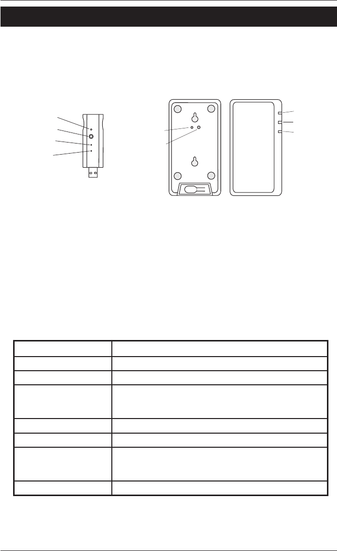
4.0 Switch Buttons and Indicators
The switch buttons and indicators (LEDs) are used during connection to the network
and also provide status information. Figure 6 shows the location of the buttons and
LEDs on the interface units.
USB ZB Interface
5200UZI WHC2_5921
Ethernet ZB Interface
5200EZI WHC2_5922
Reset button
Setup button
Back side Front side
LEDs
Power LED
ZigBee LED
Power
Ethernet
ZigBee
Reset button
Setup button
Figure 6. Location of switch buttons and LEDs on the interface units.
The Setup Button is used for E-mode actions, such as joining a ZigBee network or
disconnecting from a ZigBee network.
The Reset Button restores the ZigBee settings to the default values. On the EZI ZB
interface unit to reset the IP configuration, you must ‘long-press’ the SETUP button.
The Power LED indicates that the interface unit is connected to a suitable source of
power.
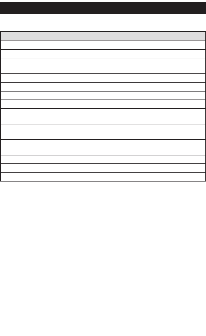
The ZigBee LED shows the current state of the connection to a ZigBee network.
Refer to the table.
The Ethernet LED (Ethernet ZB Interface only) shows the state of the connection to
the local Ethernet network.
Indicator State Meaning
Orange - continuous Not joined to a network.
Orange - flashing slowly Attempting to join a network.
Green - continuous Connected to a network. If no open network is found
within 30 seconds, the LED goes back to the Orange-
continuous mode.
Green - flashing Responding to a ZigBee identity request
Off Connected to an active network.
Red - flashing Failed due to an error (such as multiple networks open).
The LED will flash Red two times slowly and then go back
to Orange-continuous mode.
Orange - flashing rapidly Firmware is being updated--do not unplug

9 of 20
5200UZI WHC2_5921 and 5200EZI WHC2_5922 USB ZB Interface and Ethernet ZB Interface User’s Manual
© 2012 Schneider Electric. All Rights Reserved.
5.0 Installation
The installation steps for the USB and Ethernet ZB interfaces differ slightly. The
following sections tell you how to install the type of interface you are using. This
User’s Manual assumes that you have a working ZigBee network and that you have
access to the CIS Web site on the Internet.
If you are installing multiple ZB interfaces at a site, perform the connection and
commissioning steps for each network separately. Note that only one ZB interface of
either type can communicate with a single ZigBee network. If you are working with
multiple ZigBee networks, be sure to give them unique names using Zoolkit.
5.1 USB ZB Interface Unit
Read the requirements before installing the USB ZB Interface.
Requirements
• Load the Zoolkit software application on the PC. The USB ZB interface unit
requires special hardware driver files that are included with Zoolkit. The software
setup program can be freely downloaded from the CIS Web site:
http://www.clipsal.com/cis/ On the Technical page, select Downloads.
• There must be a free USB port on the PC. At this time Zoolkit runs only on a
Windows operating system. For other system requirements, refer to Zoolkit
documentation.
• There must be a working ZigBee network that the interface unit can join. The
typical range limit for reliable connectivity is 20 metres.
• If you are installing the USB ZB interface in a Wiser Home Control, you should
configure the Wiser unit (with Toolkit and PICED software) before installing the
USB ZB interface. Zoolkit software is designed to work with the Wiser unit. Refer
to the Wiser Home Control installation documents.
Follow these steps when installing the USB ZB Interface.
1. Start the Zoolkit software application on the PC where you plan to install the
USB ZB interface unit. If you are using a Wiser Home Control as the location for
the interface unit, the Wiser unit must be operational.
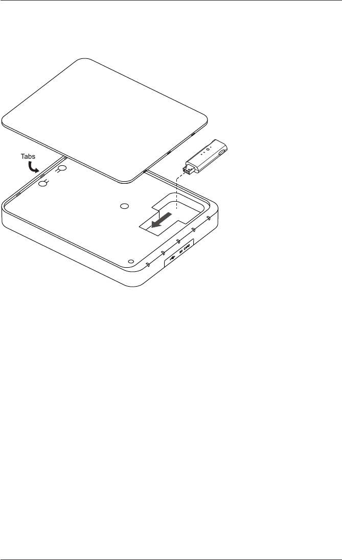
2. Install the USB ZB interface unit in an active USB port on the PC or in the
special location provided under the cover of the Wiser Home Control unit. Refer
to Figure 2 and Figure 7 for more information.
The power indicator should be on and the ZigBee status LED should be in the
Orange - continuous state.
3. Make certain that only one local ZigBee network is available for the interface unit
to join. Make sure that the network is within range and is currently operational.
4. Set the ZigBee network in its setup mode so that the interface unit can join.
Continued on the next page.
10 of 20
5200UZI WHC2_5921 and 5200EZI WHC2_5922 USB ZB Interface and Ethernet ZB Interface User’s Manual
© 2012 Schneider Electric. All Rights Reserved.
4. Press and release the Setup button. This causes the interface unit to attempt to
join the ZigBee network using E-mode.
The ZigBee status LED should be in an orange -flashing state and then switch
to the green - continuous state.
Wiser Home Control Mk 2
USB ZB Interface
5200UZI WHC2_5921
Figure 7. USB ZB Interface installation in a Wiser Home Control
5. After the interface unit is connected to the ZigBee network, you can return the
network to normal operation. The ZigBee status LED should turn off to show
that the interface unit is connected to an active ZigBee network.
6. Use the Zoolkit wizard to find the USB ZB interface unit and to identify devices
on the ZigBee network. Refer to Zoolkit help files and tutorials for more
information .

11 of 20
5200UZI WHC2_5921 and 5200EZI WHC2_5922 USB ZB Interface and Ethernet ZB Interface User’s Manual
© 2012 Schneider Electric. All Rights Reserved.
5.2 Ethernet ZB Interface
Read the requirements before installing the Ethernet ZB Interface.
Requirements
• Load the Zoolkit software application and the Control System IP Utility on the
PC. The software setup programs can be freely downloaded from the CIS Web
site:
http://www.clipsal.com/cis/ On the Technical page, select Downloads.
• A power outlet is required for the power supply.
• There must be a working ZigBee network that the interface unit can join. The
typical range limit for reliable connectivity is 20 metres.
Follow these steps when installing the Ethernet ZB Interface.
1. Start the Zoolkit software application on a PC that is on the Ethernet network
where the Ethernet ZB interface will be installed.
2. Connect a Cat.5e network cable from the Ethernet router or switch to network
connector on the Ethernet ZB interface unit. A cable is provided with the unit.
Refer to Figure 1 and Figure 4.
3. Connect the power supply’s cable end to the jack on the Ethernet ZB interface
unit, and then plug the power supply into a nearby power outlet.
The Power indicator should be on and the ZigBee status LED should be in the
orange - continuous state. There should also be activity on the Ethernet LED .
4. Make certain that only one local ZigBee network is available for the interface unit
to join. Make sure that the network is within range and is currently operational.
5. Set the ZigBee network in its setup mode so that the interface unit can join.
6. Press and release the Setup button. This causes the interface unit to attempt to
join the ZigBee network using E-mode.
The ZigBee status LED should be in an orange -flashing state and then switch to
the green - continuous state.
7. After the interface unit is connected to the ZigBee network, you can return the
network to normal operation. The ZigBee status LED should turn off to show that
the interface unit is connected to an active ZigBee network.
8. Use the Control System IP Utility to configure the IP address of the Ethernet ZB
Interface unit on the local network (VLAN).
9. Use the Zoolkit wizard to find the Ethernet ZB interface unit and to identify
devices on the ZigBee network. Refer to Zoolkit help files and tutorials for more
information .

12 of 20
5200UZI WHC2_5921 and 5200EZI WHC2_5922 USB ZB Interface and Ethernet ZB Interface User’s Manual
© 2012 Schneider Electric. All Rights Reserved.
6.0 Commissioning and Troubleshooting
The Zoolkit Wizard follows a series of steps using dialog windows that require your
input. The user interface is similar to many other applications. The Zoolkit application
does the following:
• Loads device drivers on the PC as needed.
• Starts up the Zoolkit user interface (UI) and a wizard to guide you through
various tasks.
• Locates and identifies the ZB interface unit or units. The user can rename the
units for ease of identification and commissioning tasks.
• Finds the ZigBee network that is connected to the ZB interface unit.
• Identifies the devices on the ZigBee network and allows you to cycle them
through their functions. Refer to Zoolkit help and tutorial files.
• Creates a file that the PICED software program uses to monitor and control
the ZigBee devices locally, or remotely over the Internet. PICED is used with
the Wiser Home Control and also with touch screen products from Schneider
Electric.
6.1 Troubleshooting
If you have problems, try these remedies first. If you are unable to resolve the
problem, contact your local Schneider Electric office or Technical Support.
The basic troubleshooting flow is as follows:
1. Check the physical connections between the ZB interface unit and the PC,
Wiser Home Control, Ethernet router and power supply.
2. Verify that the ZB interface unit can connect to the ZigBee network using the
E-mode method. The ZigBee status indicator should behave as described in
Section 4. Make sure that the ZB interface unit is within 20 metres of the
ZigBee network.
3. If the Zoolkit software wizard cannot locate the ZB interface device, try the
following procedure:
a. Check the IP address using the IP Utility program.
b. Make sure that the Zoolkit program is not being blocked by a firewall or
by anti-virus software.
c. Check for error messages generated by Zoolkit.
d. Disconnect and reconnect the ZB interface.
e. Shut down and then restart the Zoolkit software application.
4. If Zoolkit finds the ZB interface but cannot see the ZigBee network, try rejoining
the ZB interface to the ZigBee network manually using E-mode.

13 of 20
5200UZI WHC2_5921 and 5200EZI WHC2_5922 USB ZB Interface and Ethernet ZB Interface User’s Manual
© 2012 Schneider Electric. All Rights Reserved.
6.2 Reset Button
Using the reset button on the USB ZB interface will reset the ZigBee network
configuration settings.
To reset the ZigBee network configuration settings on the Ethernet ZB interface unit,
press and hold the SETUP button for a long-press, at least 5 seconds.
Before pressing the reset button, try powering the ZB interface off and on again. to
restore connectivity. The unit undergoes a power-on reset test that sets all of the
device states.
14 of 20
5200UZI WHC2_5921 and 5200EZI WHC2_5922 USB ZB Interface and Ethernet ZB Interface User’s Manual
© 2012 Schneider Electric. All Rights Reserved.
7.0 Specifications
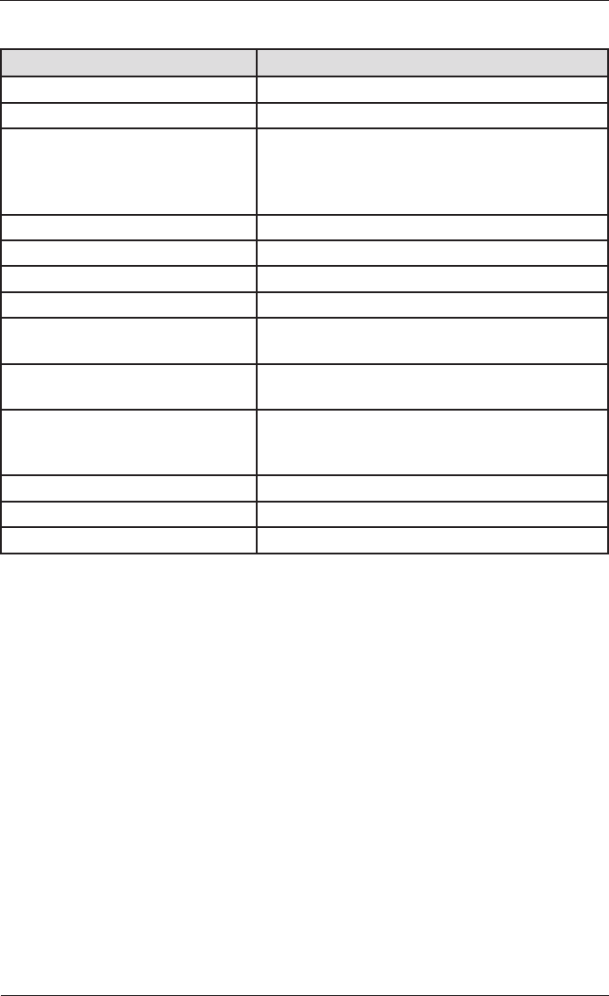
7.1 5200UZI WHC2_5921 USB ZB Interface
Parameter Description
Device type PC to ZigBee network interface
PC connection Active USB port (power sourced from PC)
WHC connection Dedicated port for USB ZB Interface (power
sourced from WHC)
Wireless ZigBee compliant
Radio frequency 2.4GHz, ISM band standard
Radiated power Less than 1mW
Signal range 20m (indoor space)
Application Indoor control of switches, relays, and motors. Not
recommended for medical applications.
User controls Setup pushbutton switch
Reset switch
Indicator LEDs Power
ZigBee status, multi-colour
Software Zoolkit configuration and management software
Ambient operating temperature 0°C to 40°C
Operating humidity 0 to 95% RH, non-condensing
15 of 20
5200UZI WHC2_5921 and 5200EZI WHC2_5922 USB ZB Interface and Ethernet ZB Interface User’s Manual
© 2012 Schneider Electric. All Rights Reserved.
7.2 5200EZI WHC2_5922 Ethernet ZB Interface
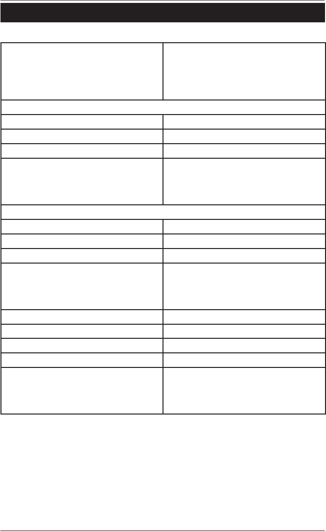
Parameter Description
Device type Ethernet to ZigBee network interface
Ethernet connection Ethernet modem or router
Power supply AC power adapter, input voltage 100 to 240V
a.c., input frequency 50/60Hz, output 24 V d.c.
1.25A, manufacutrer FranMar, model number
FRA030E-S241
Wireless ZigBee compliant
Radio frequency 2.4GHz, ISM band standard
Radiated power Less than 1mW
Signal range 20m (indoor space)
Application Indoor control of switches, relays, and motors. Not
recommended for medical applications.
User controls Setup pushbutton switch
Reset switch
Indicator LEDs Power
ZigBee status, multi-colour
Ethernet, multi-colour
Software Zoolkit configuration and management software
Ambient operating temperature 0°C to 40°C
Operating humidity 0 to 95% RH, non-condensing
16 of 20
5200UZI WHC2_5921 and 5200EZI WHC2_5922 USB ZB Interface and Ethernet ZB Interface User’s Manual
© 2012 Schneider Electric. All Rights Reserved.
8.0 Standards Complied
Declarations of Conformity
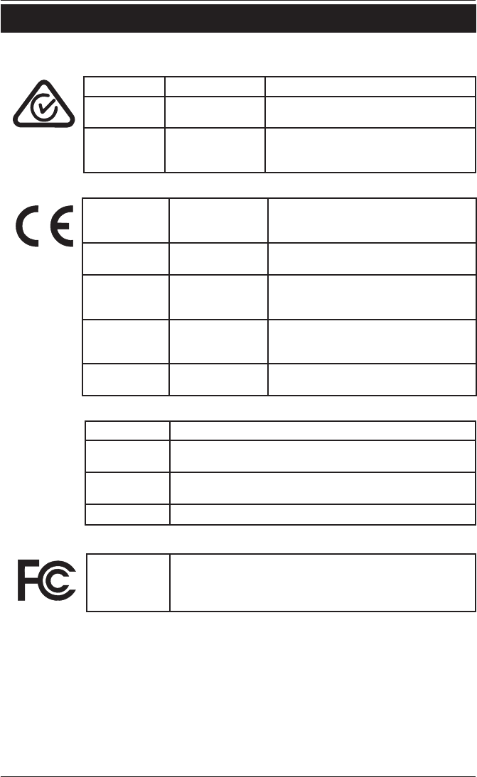
Australian/New Zealand EMC & Electrical Safety Frameworks and Standards
Regulation Standard Title
EMC AS/NZS CISPR 22 Information Technology Equipment – Radio
disturbance characteristics
RF AS/NZS 4268 Radio Equipment and Systems – Short
range devices – Limits and methods of
measurement
European Directives and Standards
European
Council
Directive
Standard Title
EMC Directive
2004/108/EC
EN 301 489-17 Radio Equipment – Electromagnetic
Compatibility and Radio Spectrum Matters
R&TTE Directive
1999/5/EC
EN 300 328 Data Transmission Equipment 2.4GHz ISM
band – Electromagnetic Compatibility and
Radio Spectrum Matters
Low Voltage
Directive
2006/95/EC
EN 60950-1 Information Technology Equipment –Safety
(EZI ZB Interface)
RoHS
2002/95/EC
Reduction of hazardous substances
International Directives and Standards
Standard Title
CISPR 22 Information Technology Equipment – Radio disturbance
characteristics – Limits and methods of measurement
CISPR 24 Information Technology Equipment – Immunity
– Limits and methods of measurement
IEC 60950-1 Information Technology Equipment – Safety (EZI ZB Interface)
U.S. FCC Regulations
FCC Title 47
Part 15, Subpart B and Subpart C
FCC ID No. : WZCS1B15258 (UZI ZB interface)
WZCS1B13237 (EZI ZB interface)
This device complies with part 15 of the FCC Rules. Operation is subject to the following two conditions:
(1) this device may not cause harmful interference, and (2) this device must accept any interference
received, including interference that may cause undesirable operation.
Class B Product
Note: This equipment has been tested and found to comply with the limits for a Class B digital device,
pursuant to Part 15 of the FCC Rules. These limits are designed to provide reasonable protection against
harmful interference in a residential installation. This equipment generates, uses and can radiate radio
frequency energy and, if not installed and used in accordance with the instructions, may cause harmful
interference to radio communications. However, there is no guarantee that interference will not occur in a
particular installation.
17 of 20
5200UZI WHC2_5921 and 5200EZI WHC2_5922 USB ZB Interface and Ethernet ZB Interface User’s Manual
© 2012 Schneider Electric. All Rights Reserved.
If this equipment does cause harmful interference to radio or television reception, which can be determined
by turning the equipment off and on, the user is encouraged to try to correct the interference by one or more
of the following measures:
•Reorientorrelocatethereceivingantenna.
•Increasetheseparationbetweentheequipmentandreceiver.
•Connecttheequipmentintoanoutletonacircuitdifferentfromthattowhichthereceiverisconnected.
•Consultthedealeroranexperiencedradio/TVtechnicianforhelp.
Subpart C Intentional, Unintentional and Incidental Radiator
Operation of an intentional, unintentional, or incidental radiator is subject to the conditions that no harmful
interference is caused and that interference must be accepted that may be caused by the operation of an
authorized [licensed] radio station, by another intentional or unintentional radiator, by industrial, scientific
and medical (ISM) equipment, or by an incidental radiator.
Singapore (IDA)
Complies with IDA standards: DA104328 (UZI ZB Interface)
Pending (EZI ZB Interface)
China (SRRC)
CMIIT ID number: Pending (UZI ZB Interface)
Pending (EZI ZB Interface)
ZigBee Alliance
ZigBee Certified Product – Home Automation profile
Do not dispose of this product to landfill or by incineration. This product
should be disposed of by a licenced electronic waste disposal agency.
In some locations it is an offense to dispose of electronic items improperly.
Warning:
Any changes or modifications not expressly approved by Clipsal Integrated Systems or
Schneider Electric could void the user’s authority to operate this equipment.
18 of 20
5200UZI WHC2_5921 and 5200EZI WHC2_5922 USB ZB Interface and Ethernet ZB Interface User’s Manual
© 2012 Schneider Electric. All Rights Reserved.
9.0 Installation Notes
Site Location
Installer information
Interface Unit Product ID:
Serial Number: MAC:
IP Address: ZB network:
Other details:
Interface Unit Product ID:
Serial Number: MAC:
IP Address: ZB network:
Other details:
Interface Unit Product ID:
Serial Number: MAC:
IP Address: ZB network:
Other details:

19 of 20
5200UZI WHC2_5921 and 5200EZI WHC2_5922 USB ZB Interface and Ethernet ZB Interface User’s Manual
© 2012 Schneider Electric. All Rights Reserved.
10.0 Two-Year Warranty
The USB and Ethernet ZB Interface units are covered by a two-year warranty
against manufacturing defects.
Warranty Statement
The benefits conferred herein are in addition to, and in no way shall be deemed to derogate;
either expressly or by implication, any or all other rights and remedies in respect to the
Shneider Electric product, which the consumer has in the location where the product is sold.
The warrantor is Schneider Electric.
This Schneider Electric product is guaranteed against faulty workmanship and materials for a
period of two (2) years from the date of installation.
Schneider Electric reserves the right, at its discretion, to either repair free of parts and labour
charges, replace or offer refund in respect to any article found to be faulty due to materials,
parts or workmanship.
This warranty is expressly subject to the Schneider Electric product being installed, wired,
tested, operated and used in accordance with the manufacturer’s instructions. Any alterations
or modifications made to the product without permission of Clipsal Integrated Systems or
Schneider Electric might void the warranty.
Schneider Electric shall meet all costs of a claim. However, should the product that is the
subject of the claim be found to be in good working order, all such costs shall be met by the
claimant.
When making a claim, the consumer shall forward the Schneider Electric product to the
nearest Clipsal or Schneider Electric office. Provide adequate particulars of the defect within
28 days of the fault occurring. The product should be returned securely packed, complete
with details of the date and place of purchase, description of load, and circumstances of
malfunction.
For all warranty enquiries, contact your local Clipsal or Schneider Electric sales representative.
The address and contact number of your nearest sales office can be found at http://
www.clipsal.com/locations or by telephoning Technical Support 1300 722 247 (CIS
Technical Support Hotline for Australia only).

F2406/01
October 2012
Schneider Electric (Australia) Pty Ltd
Contact us: clipsal.com/feedback
National Customer Care Enquiries:
Tel 1300 2025 25
Fax 1300 2025 56
Schneider Electric (Australia) Pty Ltd reserves the right to
change specifications, modify designs and discontinue items
without incurring obligation and whilst every effort is made to
ensure that descriptions, specifications and other information
in this catalogue are correct, no warranty is given in respect
thereof and the company shall not be liable for any error therein.
© 2012 Schneider Electric. All Rights Reserved.
Trademarks are owned by Schneider Electric Industries SAS or
its affiliated companies.