Schneider Electric Weather Radio Ion7550 Users Manual PowerLogic / ION7650 Installation Guide
ION7650 to the manual f3d05de6-4626-4231-92bb-2385f84acfb1
2015-02-06
: Schneider-Electric Schneider-Electric-Weather-Radio-Ion7550-Users-Manual-526989 schneider-electric-weather-radio-ion7550-users-manual-526989 schneider-electric pdf
Open the PDF directly: View PDF ![]() .
.
Page Count: 28
- PowerLogic ION7550 / ION7650 Models
- Available Options
- Before You Begin
- Meter Overview
- Unit Dimensions
- Step 1: Mount the Meter
- Step 2: Wire the Ground Terminal
- Step 3: Wire the Digital I/O and Analog I/O
- Step 4: Wire the Voltage and Current Inputs
- 4-Wire Wye, 3-Element, Direct Connection Diagram
- 4-Wire Wye, 3-Element, 3 PTs Connection Diagram
- 4-Wire Wye, 2º-Element, 2 PTs Connection
- 3-Wire Solid-Grounded Wye, 3-Element, Direct Connection
- 3-Wire Delta, 2º-Element, Direct Connection
- 3-Wire Delta, 2-Element 2 PTs & 2 CTs
- 3-Wire Delta, 2º-Element, 2 PTs & 3 CTs
- Single Phase Connection Diagram
- Using Potential Transformers
- Step 5: Wire the Communications
- Step 6: Wire the Power Supply
- Step 7: Power Up the Meter
- Step 8: Set Up the Meter Using the Front Panel
- Step 9: Verify Meter Operation
- Step 10: View Meter Data
PowerLogic® ION7550 / ION7650
Energy & Power Quality Meter
Installation Guide
December 2007
PowerLogic ION7550 / ION7650 Installation Guide
© 2007 Schneider Electric. All rights reserved. 3
Danger
This symbol indicates the presence of dangerous voltage within and outside the product enclosure
that may constitute a risk of electric shock, serious injury or death to persons if proper precautions
are not followed.
Caution
This symbol alerts the user to the presence of hazards that may cause minor or moderate injury to
persons, damage to property or damage to the device itself, if proper precautions are not followed.
Note
This symbol directs the user’s attention to important installation, operating and maintenance
instructions.
Installation Considerations
Installation and maintenance of the PowerLogic ION7550 / ION7650 meter should only be performed by qualified,
competent personnel that have appropriate training and experience with high voltage and current devices. The meter
must be installed in accordance with all local and national electrical codes.
DANGER
Failure to observe the following instructions may result in severe injury or death.
During normal operation of the ION7550 / ION7650 meter, hazardous voltages are present on its termi-
nal strips, and throughout the connected potential transformer (PT), current transformer (CT), digital (sta-
tus) input, control power and external I/O circuits. PT and CT secondary circuits are capable of generating
lethal voltages and currents with their primary circuit energized. Follow standard safety precautions while
performing any installation or service work (i.e. removing PT fuses, shorting CT secondaries, etc.).
The terminal strips on the meter base should not be user-accessible after installation.
Do not use digital output devices for primary protection functions. These include applications where the
devices perform energy limiting functions or provide protection of people from injury. Do not use the
ION7550 / ION7650 in situations where failure of the devices can cause injury or death, or cause suffi-
cient energy to be released that can start a fire. The meter can be used for secondary protection functions.
Do not HIPOT/Dielectric test the digital (status) inputs, digital outputs, or communications terminals. Refer
to the label on the ION7550 / ION7650 meter for the maximum voltage level the device can
withstand.
CAUTION
Observe the following instructions, or permanent damage to the meter may occur.
The ION7550 / ION7650 meter offers a range of hardware options that affect input ratings. The
ION7550 / ION7650 meter’s serial number label lists all equipped options. Applying current levels incom-
patible with the current inputs will permanently damage the meter. This document provides installation
instructions applicable to each hardware option.
The ION7550 / ION7650 meter’s chassis ground must be properly connected to the switchgear earth
ground for the noise and surge protection circuitry to function correctly. Failure to do so will void the
warranty.
Terminal screw torque: Barrier-type (current, voltage, and relay terminal screws: 1.35 Nm (1.00 ft-lbf)
max. Captured-wire type (digital inputs/outputs, communications, power supply: 0.90 Nm
(0.66 ft.lbf) max.
FCC Notice
This equipment has been tested and found to comply with the limits for a Class A digital device, pursuant to Part 15
of the FCC Rules. These limits are designed to provide reasonable protection against harmful interference when the
equipment is operated in a commercial environment.

PowerLogic ION7550 / ION7650 Installation Guide
4 © 2007 Schneider Electric. All rights reserved.
This equipment generates, uses, and can radiate radio frequency energy and, if not installed and used in accordance
with the instruction manual, may cause harmful interference to radio communications. Operation of this equipment
in a residential area is likely to cause harmful interference in which case the user will be required to correct the
interference at his own expense.
The Ringer Equivalence Number (REN) for the ION7550 / ION7650 optional internal modem is 0.6. Connection to
the ION7550 / ION7650 internal modem should be made via an FCC Part 68 compliant telephone cord (not
supplied). The ION7550 / ION7650 cannot be used on a public coin phone service or party line services.
Network Compatibility Notice for the Internal Modem
The internal modem in meters equipped with this option is compatible with the telephone systems of most countries
in the world. Use in some countries may require modification of the internal modem’s initialization strings. If problems
using the modem on your phone system occur, please contact Schneider Electric Technical Support.
Standards Compliance
Made by Power Measurement Ltd.
PowerLogic, ION, ION Enterprise, MeterM@il, WebMeter and Modbus are either trademarks or registered
trademarks of Schneider Electric.
Covered by one or more of the following patents:
U.S. Patent No's 7010438, 7006934, 6990395, 6988182, 6988025, 6983211, 6961641, 6957158,
6944555, 6871150, 6853978, 6825776, 6813571, 6798191, 6798190, 6792364, 6792337, 6751562,
6745138, 6737855, 6694270, 6687627, 6671654, 6671635, 6615147, 6611922, 6611773, 6563697,
6493644, 6397155, 6236949, 6186842, 6185508, 6000034, 5995911, 5828576, 5736847, 5650936,
D505087, D459259, D458863, D443541, D439535, D435471, D432934, D429655, D427533.
CSA: Certified to CAN/
CSA C22.2 No.1010-1
Certified to
UL 3111
PowerLogic ION7550 / ION7650 Installation Guide
© 2007 Schneider Electric. All rights reserved. 5
PowerLogic ION7550 / ION7650 Models
Integrated Display Model
Comes with front optical port.
TRAN (transducer) Model
The TRAN model has no display.
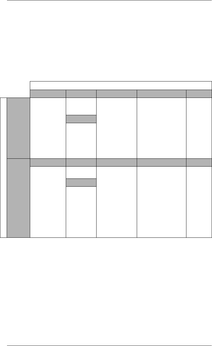
Available Options
Notes
1Standard = password protected, no locking or sealing.
2RMANSI = ANSI C12.16 approved revenue meter; meets ANSI C12.20
class 0.2 accuracy standards.
Option
Form Factor Current Inputs COM I/O Security
Model
ION7550
Integ. Display
TRAN
5 MB memory
10 MB memory
Up to 256
sampling rate
Standard
(5 Amp)
1 Amp
Standard (RS-232,
RS-485, optical)
Ethernet RJ45
Ethernet Fiber
Modem
Standard (8 digital
inputs, 3 Form C relays,
4 Form A outputs)
Extra 8 digital inputs
Four 0-1mA analog
inputs
Four 0-20 mA analog
inputs
Four -1 to 1mA analog
outputs
Four 0-20 mA analog
outputs
Standard1
RMANSI2
Power Supply
Standard
Low Voltage
DC
ION7650
Form Factor Current Inputs COM I/O Security
Integ. Display
TRAN
5 MB memory
10 MB memory
Up to 512
sampling rate
(standard)
1024 sampling
rate (optional)
EN50160
compliance
IEC61000-4-30
Class A
compliance
Same as
ION7550
Same as
ION7550
Same as ION7550 Same as
ION7550
Power Supply
Same as
ION7550
PowerLogic ION7550 / ION7650 Installation Guide
6 © 2007 Schneider Electric. All rights reserved.
Before You Begin
Before installing the meter, familiarize yourself with the steps in this guide and
read the safety precautions presented on the “Installation Considerations”
page.
DANGER
Do not power up the meter until the current and voltage wiring is completed.
Recommended Tools
Phillips screwdriver
Precision flat-head screwdriver
Wire cutters / stripper
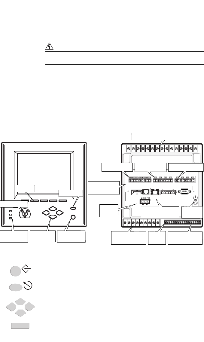
Meter Overview
Front Panel Button Functions
PROG/SELECT: Press the PROG/SELECT (program or select) button to enter Setup
mode. In Setup mode, press the PROG/SELECT button to accept changes.
ESC: Press the ESC (Escape) button to return to a higher menu or discontinue a
configuration change.
NAVIGATION: Press the UP / DOWN arrow buttons to highlight menu items, or
increment / decrement numbers.
Press the LEFT or RIGHT arrow buttons to move to an adjacent digit.
SOFTKEY: Press a SOFTKEY button to select the parameter that you want to
configure from the sub-menus.
Navigation
Buttons
PROG/SELECT
Button
Softkeys
ESC Button
Communications
Card
Form C
Digital Outputs
Digital
Inputs
Form A
Digital Outputs
Digital Inputs Analog Inputs Analog Outputs
Voltage and Current Inputs
Power
Supply Ground
Te r m i n al
Meter Front Meter Back
Optical Port
I/O Expansion
Card
Operational
LEDs
ESC
PROG
PowerLogic ION7550 / ION7650 Installation Guide
© 2007 Schneider Electric. All rights reserved. 7
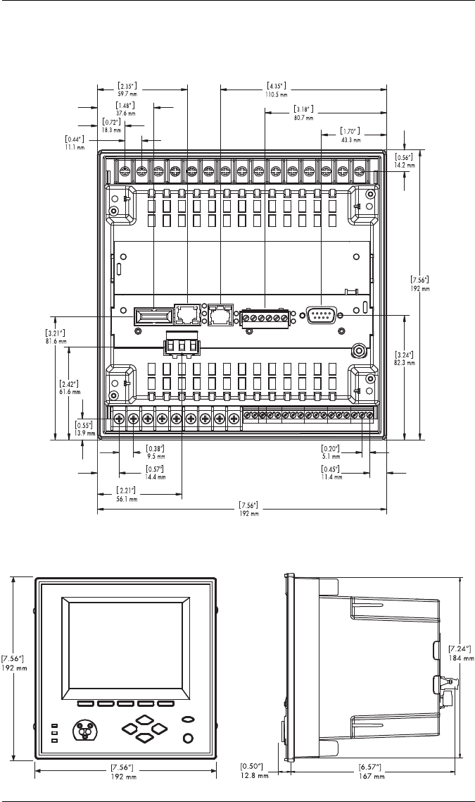
Unit Dimensions
Basic Model — Rear View
Basic Model — Front View Basic Model — Side View
PowerLogic ION7550 / ION7650 Installation Guide
8 © 2007 Schneider Electric. All rights reserved.
Step 1: Mount the Meter
Environmental Specifications
Meter Battery Considerations
The meter’s battery life expectancy depends on both temperature and the
amount of time the meter is without power. For typical installations, the
battery should last 20 years or more. If the meter is not powered, the battery
will last a minimum of 7 years at room temperature.
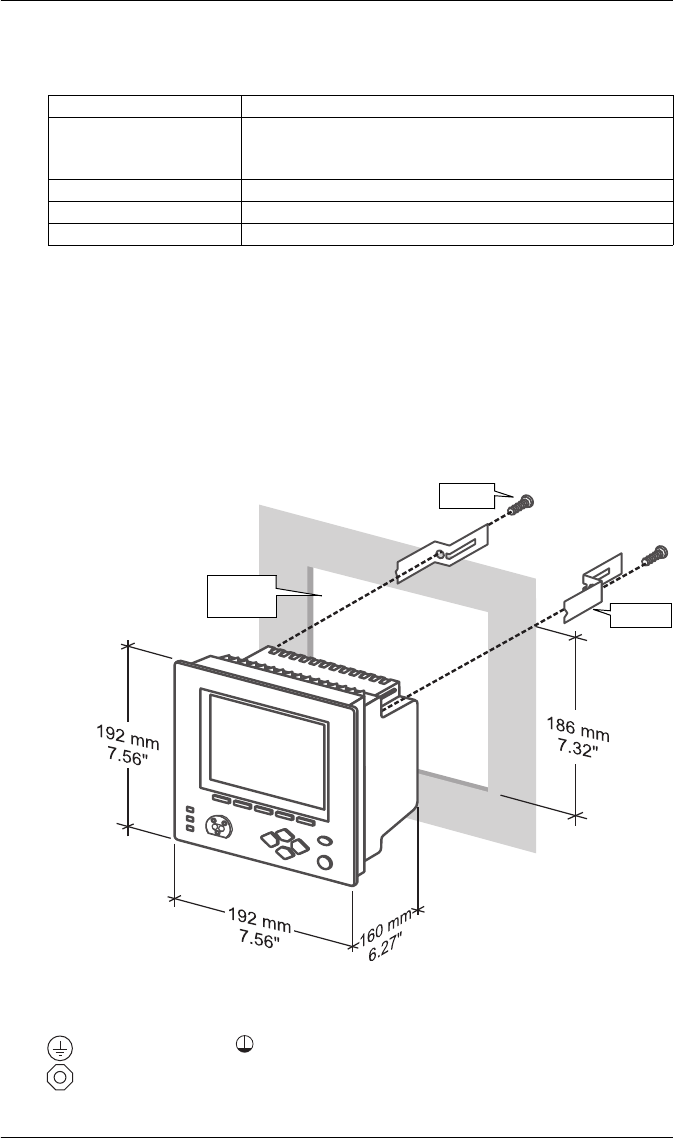
Integrated Display Model
1. Fit the meter into the DIN standard 192 cutout (186 mm by 186 mm).
2. Slide the four brackets into their slots on the back of the meter and secure
using the four Phillips head screws. Do not overtighten.
Step 2: Wire the Ground Terminal
Connect the terminal to a good earth ground with a 2.1 mm2 (14 AWG)
wire. Ensure that the terminal nut is tightened down securely onto the ground
wire. Do not use metal door hinges as a grounding point.
Mounting Location Indoor use
Operating Range
-20 to +70ºC (-4 to +158ºF) Standard Power Supply
-20 to +50ºC (-4 to +122ºF) Low Voltage DC Power Supply
No formation of ice
Display Operating Range -20 to +70ºC (-4 to +158ºF)
Storage Range -40 to +85ºC (-40 to +185ºF)
Relative Humidity Range 5 to 95% non-condensing
Screw
Bracket
DIN 192
Cutout
PowerLogic ION7550 / ION7650 Installation Guide
© 2007 Schneider Electric. All rights reserved. 9
Step 3: Wire the Digital I/O and Analog I/O
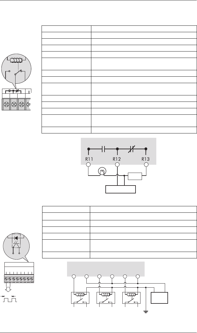
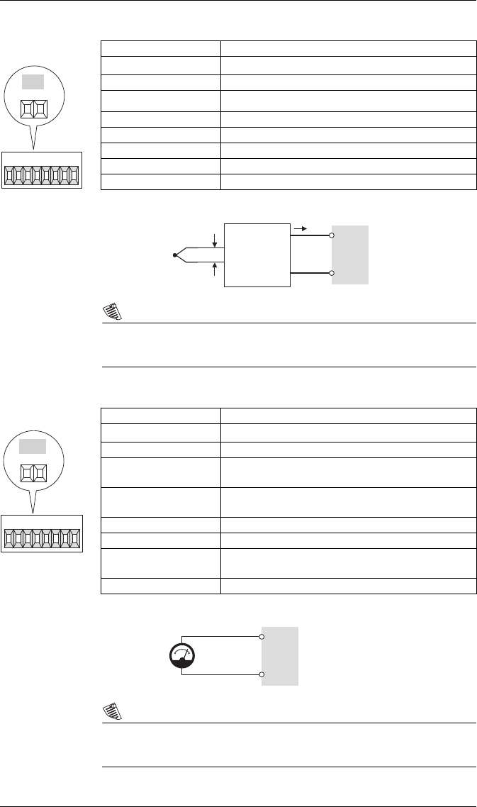
Form C Digital Outputs: Mechanical Relays R1 - R3
Form A Digital Outputs: Solid State Relays D1 - D4
Type Form C (R1, R2, R3)
Contacts K (common), Y (NO), Z (NC)
Wire Use wiring that is appropriate for the application
Connector Ring or split ring connector
Voltage Rating 250 VAC / 30 VDC
Rated Load @
Rated Voltage
Resistive: 10 A (AC/DC)
Inductive (PF=0.4): 7.5 A (AC) / 5 A (DC)
Max. Voltage 380 VAC / 125 VDC between K and NO/NC
MOV Protection 300 V max. between NO and NC
Max. Load @
Max. Voltage 3 A (AC) / 0.2 A (DC)
Turn-On Time 15 ms max.
Isolation 5,000 VAC for 60 s
Turn-Off Time 5 ms max.
Lifetime No load = 10,000,000 operations
Rated voltage and load = 100,000 operations
Update time ½ cycle or 1 s
R
11
R
12
R
13
R
21
R12
R11 R13
Internal Form C
Mechanical
Relay
External Supply
Alarm Lamp
NCNO
Load
Meter K
Mechanical
relays should
always be
protected by
external fuses
Type For m A (D1, D2, D3, D4)
Wire 1.3 to 0.1 mm2 (16 to 28 AWG)
Signal Type Continuous or pulse
Max. Load Voltage 30 VDC
Max. Load Current 80 mA per channel
Isolation Optically isolated; max. 5,000 V RMS isolation
(UL-E91231)
Scan Time ½ cycle or 1 s
DIGITAL OUTPUTS
D3
-
+
D2
-
+
D4
-
+
D1
-
+
1.8 Wh
+
_
D1
Internal Form A
Solid State Relay
+
+
_
D3
_
D2
+
_ _
+
_
+
_
+
_
D1
+
D4 output is factory-configured to pulse once every 1.8 Wh for Class 20 meters,
or once every 0.18 Wh for Class 2 meters (for calibration testing purposes).
Meter
External
Relays External Supply
30VDC max
PowerLogic ION7550 / ION7650 Installation Guide
10 © 2007 Schneider Electric. All rights reserved.
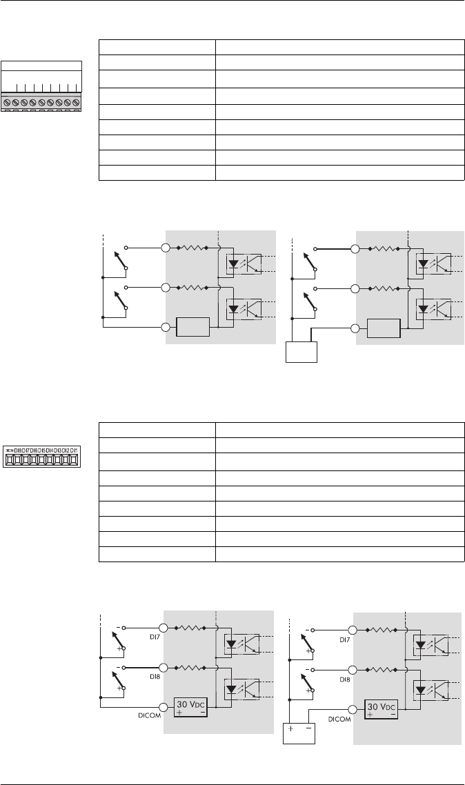
Digital Inputs: S1 - S8
Digital Inputs (Meter Ordering Option): DI1 - DI8
Type Self-excited (internal 30 VDC supply)
Application Dry contact sensing, or with external excitation
Wire 1.3 to 0.1 mm2 (16 to 28 AWG)
Min. Pulse Width 1 ms
Max. Pulse Rate 20 pulses per second
Timing Resolution 1 ms
Updated ½ cycle (after timing resolution)
Isolation to Ground max. 200 VDC for 10s
Max. External Voltage 130 VDC continuous
S
C
O
M
S
1
S
2
S
3
S
4
S
5
S
6
S
7
S
8
DIGITAL INPUTS
_
+
S8
S7
SCOM
+
_
30 VDC
+
_
+
_
S8
S7
SCOM
+
_
30 VDC
+
_
+
_
Internal Excitation External Excitation
Optically-
coupled switch
External Supply
130 VDC max
Meter Meter
Optically-
coupled switch
Type Self excited (internal 30 VDC supply)
Application Dry contact sensing, or with external excitation
Wire 1.3 to 0.1 mm2 (16 to 28 AWG)
Min. Pulse Width 20 ms
Max. Pulse Rate 25 pulses per second
Timing Resolution 2 ms
Updated ½ cycle (after timing resolution)
Isolation to Ground 750 VDC
Max. External Voltage 50 VDC continuous
Internal Excitation External Excitation
Optically-
coupled switch Optically-
coupled switch
External Supply
50 VDC max
Meter Meter
PowerLogic ION7550 / ION7650 Installation Guide
© 2007 Schneider Electric. All rights reserved. 11
Analog Inputs (Meter Ordering Option): AI1 to AI4
NOTE
Do not connect the analog inputs of the I/O card to the analog outputs on
the same I/O card.
Analog Outputs (Meter Ordering Option): AO1 to AO4
NOTE
Do not connect the analog outputs of the I/O card to the analog inputs on
the same I/O card.
Type Captured wire connector
Wire 1.3 to 0.1 mm2 (16 to 28 AWG)
Signal Type DC current
Available Options 0 to 20 mA (scalable 4-20 mA) or 0 to 1 mA
Input Impedance 24 Ω (0-20 mA option) or 475 Ω (0-1 mA option)
Accuracy +/– 0.3% of full scale
Update Rate 1 s
Isolation to Ground 750 V
Isolation Impedance max 400 kΩ (channel/channel)
AI4 AI3 AI2 AI1
AI3
+
-
AI1
+
-
mV mA
Example
application:
temperature
sensing
Thermocoupler Voltage-to-
Current
Transd uc er
Meter
Type Captured wire connector
Wire 1.3 to 0.1 mm2 (16 to 28 AWG)
Signal Type DC current
Available Options 0 to 20 mA (scalable 4-20 mA) or -1 to 1 mA
(scalable 0-1 mA)
Driving Capability 500 Ω (0-20 mA option) or 10 kΩ (-1 to 1 mA
option)
Accuracy +/– 0.30% of full scale
Update Rate ½ cycle or 1 s
Latency min. 1 cycle for measurement + ½ cycle for ION
+ 1 s delay for hardware
Isolation to Ground 750 V
AO3
OUT COM
AO4 A03 A02 AO1
AO1
OUT
COM
+
Example application: driving an
analog meter with the DC
current output
Meter
Analog
Meter
PowerLogic ION7550 / ION7650 Installation Guide
12 © 2007 Schneider Electric. All rights reserved.
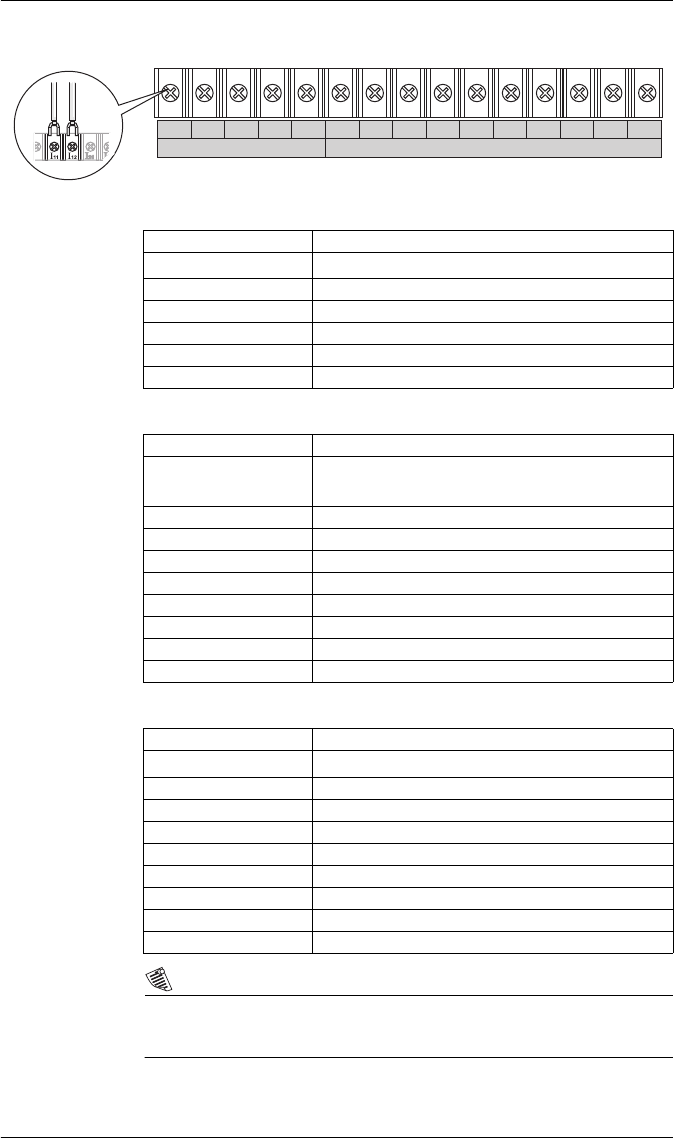
Step 4: Wire the Voltage and Current Inputs
Voltage Inputs
Current Inputs: Class 20 Current Inputs (5A Option)
Current Inputs: Class 2 Current Inputs (1A Option)
NOTE
The appropriate Volts Mode setting is included with each wiring diagram.
Refer to Step 8 to learn how to configure Volts Mode on the meter.
3~ VOLTAGE INPUTS 3~ CURRENT INPUTS
V
3
V
4
V
ref
I
11
I
12
I
21
I
22
I
31
I
32
I
41
I
42
I
51
V
1
V
2
I
52
Connector Type Ring or split ring connector
Wire Gauge 3.3 to 2.1 mm2 (12 to 14 AWG)
Rated Inputs 347 V L-N RMS /600 V L-L RMS
Fault Capture 1200 V L-N peak
Overload 1500 VAC RMS continuous
Dielectric Withstand 2500 VAC RMS at 60 Hz for 60 s
Input Impedance 5 MΩ/phase (phase - Vref)
Connector Type Ring or split ring connector
Wire Gauge 5.3 to 3.3 mm2 (10 to 12 AWG):
Use 8.4 mm2 (8 AWG) for 10-20 A applications
Input Rating 5 A, 10 A, and/or 20 A RMS
Starting Current 0.005 A RMS
Fault Capture 70 A peak
Max. Voltage 600 V RMS (CAT III IEC61010-1)
Overload 500 A RMS for 1 s, non-recurring
Dielectric Withstand 2500 VAC RMS at 60 Hz for 60 s
Burden 0.05 VA per phase (at 5 A)
Impedance 0.002 Ω per phase
Connector Type Ring or split ring connector
Wire Gauge 5.3 to 3.3 mm2 (10 to 12 AWG)
Input Rating 1 A, 2 A, 5 A, and/or 10 A RMS
Starting Current 0.001 A RMS
Fault Capture 17.5 A peak
Max. Voltage 600 V RMS (CAT III IEC61010-1)
Overload 50 A RMS for 1s, non-recurring
Dielectric Withstand 2500 VAC RMS at 60 Hz for 60 s
Burden 0.015 VA per phase (at 1 A)
Impedance 0.015 Ω per phase
PowerLogic ION7550 / ION7650 Installation Guide
© 2007 Schneider Electric. All rights reserved. 13
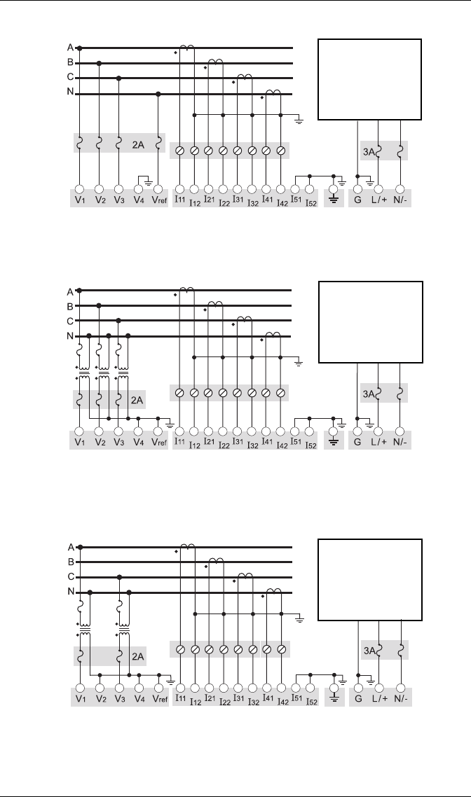
4-Wire Wye, 3-Element, Direct Connection Diagram
347 V L-N / 600 V L-L max.
VOLTS MODE = 4W-Wye
4-Wire Wye, 3-Element, 3 PTs Connection Diagram
Use PTs for voltages over 347 V L-N / 600 V L-L.
Wye (Star) wiring for PT primaries and secondaries.
VOLTS MODE = 4W-Wye
4-Wire Wye, 2½-Element, 2 PTs Connection
Phase B voltage (V2) displayed by meter is derived from phase A and
phase C, not measured. V2 will display a value even if no voltage is
present on Phase B. V2 values are only accurate for balanced loads.
VOLTS MODE = 3W-Wye
LINE
LOAD
Fuse for N/- terminal
required if its supply
source is ungrounded
Connect G terminal
to ground for AC
power source
I4 Optional
LINE
LOAD
Fuse for N/- terminal
required if its supply
source is ungrounded
Connect G terminal
to ground for AC
power source
I4 Optional
LINE
LOAD
Fuse for N/- terminal
required if its supply
source is ungrounded
Connect G terminal
to ground for AC
power source
I4 Optional
PowerLogic ION7550 / ION7650 Installation Guide
14 © 2007 Schneider Electric. All rights reserved.
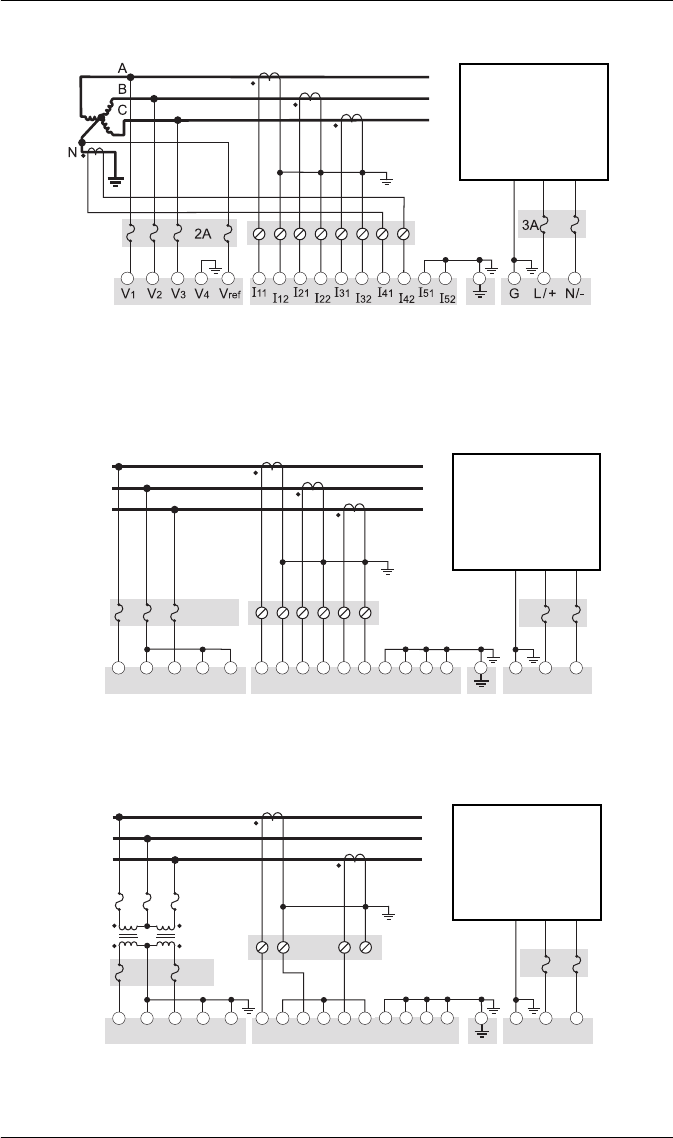
3-Wire Solid-Grounded Wye, 3-Element, Direct Connection
When the common or star point of a 3-wire Wye system is grounded,
the meter may be connected directly without using PTs, provided that the
phase voltages are within the meter’s range.
VOLTS MODE = 4W-Wye
3-Wire Delta, 2½-Element, Direct Connection
600 V L-L max.
VOLTS MODE = Delta
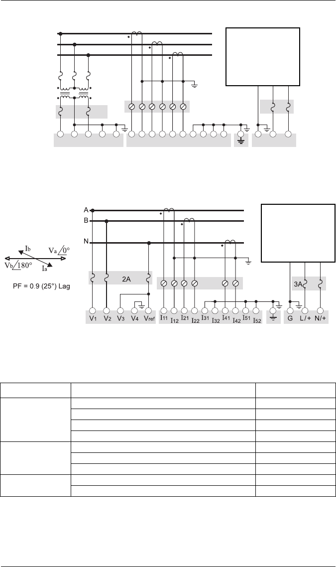
3-Wire Delta, 2-Element 2 PTs & 2 CTs
Use PTs for voltages over 600 V L-L.
VOLTS MODE = Delta
LINE
LOAD
Fuse for N/- terminal
required if its supply
source is ungrounded
Connect G terminal
to ground for AC
power source
V1V2V3Vref I11 I12 I21 I22 I31 I32
N/-L/+
G
3A
A
B
C
2A
Do not
connect
V4I41 I42 I51 I52
LINE
LOAD
Fuse for N/- terminal
required if its supply
source is ungrounded
Connect G terminal
to ground for AC
power source
V1V2V3Vref I11 I12 I21 I22 I31 I32 N/-L/+
G
3A
A
B
C
2A
V4I41 I42 I51 I52
LINE
LOAD
Fuse for N/- terminal
required if its supply
source is ungrounded
Connect G terminal
to ground for AC
power source
PowerLogic ION7550 / ION7650 Installation Guide
© 2007 Schneider Electric. All rights reserved. 15
3-Wire Delta, 2½-Element, 2 PTs & 3 CTs
Use PTs for voltages over 600 V L-L
VOLTS MODE = Delta
Single Phase Connection Diagram
277 V L-N / 554 V L-L max. Use PTs for higher voltages.
VOLTS MODE = Single
Using Potential Transformers
2A
V1V2V3Vref I11 I12 I21 I22 I31 I32
N/-L/+
G
3A
A
B
C
V4I41 I42 I51 I52
LINE
LOAD
Fuse for N/- terminal
required if its supply
source is ungrounded
Connect G terminal
to ground for AC
power source
LINE
LOAD
Fuse for N/- terminal
required if its supply
source is ungrounded
Connect G terminal
to ground for AC
power source
I4 Optional
System Mode Voltage Range Requires PTs
Wye
120 V L-N or 208 V L-L no
277 V L-N or 480 V L-L no
347 V L-N or 600 V L-L no
over 347 V L-N or 600 V L-L yes
Single Phase
120 V L-N or 240 V L-L no
277 V L-N or 554 V L-L no
over 277 V L-N or 554 V L-L yes
Delta up to 600 V L-L no
over 600 V L-L yes
PowerLogic ION7550 / ION7650 Installation Guide
16 © 2007 Schneider Electric. All rights reserved.
Step 5: Wire the Communications
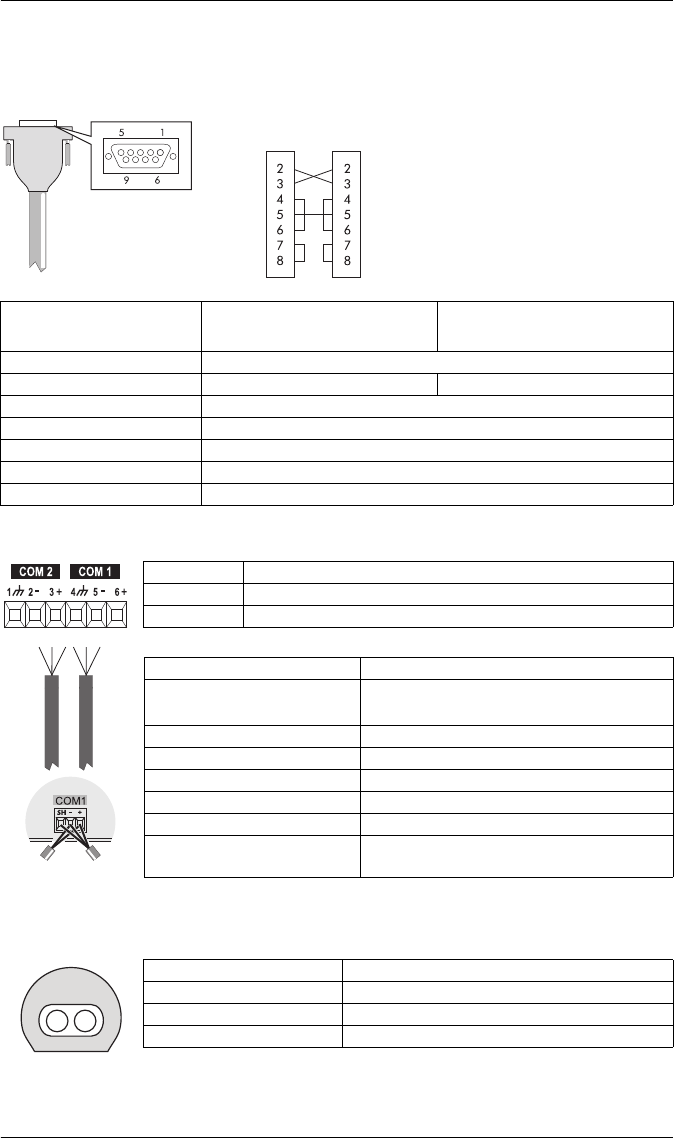
RS-232 Connections (COM1)
RS-485 Connections (COM1 and COM2)
Infrared Connections (COM4)
Null modem cable pinout
Pin 3 - Transmit Data - Pin 2
Pin 2 - Receive Data - Pin 3
Pin 7 - Request to Send- Pin 8
Pin 8 - Clear to Send- Pin 7
Pin 5 - Signal Ground- Pin 5
Pin 6 - Data Set Ready- Pin 4
Pin 4 - Data Terminal Ready- Pin 6
DB9 Null Modem
Wiring Diagram
DTE
(computer)
DTE
(meter)
Specification Meter Connected to Computer Meter Connected to External
Modem
Connector Type DB9 female end for mating with male connector on the meter
Wire Null modem RS-232 cable Straight-through RS-232 cable
Maximum Cable Length 15.2 m (50 ft)
Data Rate 300 – 115,200 bps
Isolation Optical
Duplex Full
Compliance ANSI/IEEE C37.90.1-2002 surge withstand and fast transient tests
SH RS-485 Shield (electrically connected to chassis ground)
– RS-485 Data Minus
+ RS-485 Data Plus
Connector Type Captured wire
Wire Shielded twisted pair RS-485 cable,
0.33 mm2 (22 AWG) or larger
Maximum Cable Length 1219 m (4000 ft) total for entire bus
Data Rate 300 – 115,200 bps
Maximum Devices (per bus) 32
Isolation Optical
Duplex Half
Compliance ANSI/IEEE C37.90.1-2002 surge withstand
and fast transient tests
Connect SH at
one end only
Interface ANSI C12.18 Type II optical port
Location Front of meter
Data Rate 1,200 – 19,200 bps
Duplex Half
PowerLogic ION7550 / ION7650 Installation Guide
© 2007 Schneider Electric. All rights reserved. 17
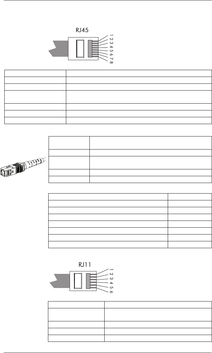
Ethernet Connections (if equipped)
10BASE-T / 100BASE-TX
100BASE-FX (Fiber)
Ethernet TCP/IP Service Ports
Internal Modem Connection (COM3 if equipped)
Pin 1: Transmit Data +
Pin 2: Transmit Data -
Pin 3: Receive Data +
Pin 6: Receive Data -
Wire Type High quality Category 5 or 6 unshielded twisted pair cable
Connector Type RJ45 modular
Maximum Length 100 m (328 ft)
Type IEEE 802.3 10/100BASE-T for 10/100 Mbps base band CSMA/CD
LANs
Data Rate 10/100 Mbps
Isolation Transformer isolated to 1500 V RMS
Max. Connections Allowed 4 simultaneous (32 via Modbus TCP/IP)
Wire Type 62.5/125 or 50/125 micrometer multimode fiber optic
cable
Connector Type SC
Maximum Length 2000 m (6562 ft) full duplex
400 m (1312 ft) half duplex
Data Rate 100 Mbps
Isolation Optical
Protocol Port
ION 7700
Modbus RTU 7701
Modbus TCP 502
EtherGate (COM1) 7801
EtherGate (COM2) 7802
DNP TCP 20,000
SMTP 25 (configurable)
SC type fiber cable
Only one EtherGate
connection per port
is allowed at a time
Pin 3: Ring
Pin 4: Tip
Connector Type RJ11
Wire Type FCC Part 68 compliant telephone cord (two male
RJ11 ends)
Data Rate 300 bps – 56 kbps
Error Correction V.42 LAPM, MNP 2-4, V.44
Data Compression V.42 bis/MNP 5
PowerLogic ION7550 / ION7650 Installation Guide
18 © 2007 Schneider Electric. All rights reserved.
Step 6: Wire the Power Supply
Step 7: Power Up the Meter
1. Ensure the ground wire is securely connected on both ends.
2. Ensure the meter’s power supply voltage is within the allowed range.
3. Power up the meter.
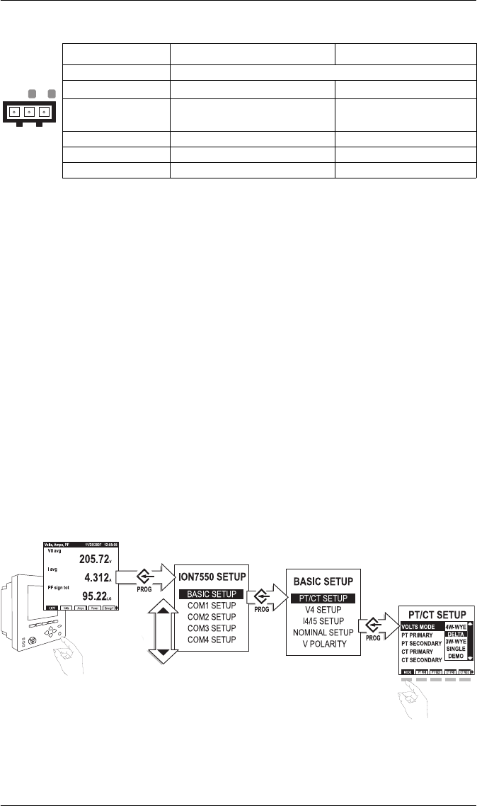
Step 8: Set Up the Meter Using the Front Panel
The following Setup screens are available for meter configuration via the
front panel:
Use the PROG/SELECT, ESC, softkeys and arrow buttons to configure settings.
The following example shows Volts Mode setup using the meter front panel.
Specification Standard Power Supply Low Voltage DC
Type Captured wire connector
Wire 3.3-2.1 mm2 (12-14 AWG) 2.1-0.8 mm2 (14-18 AWG)
Rated Inputs 85-240 VAC ±10%(47-63 Hz),
or 110-300 VDC ±10% 20-60 VDC ±10%
Dielectric Withstand 2500 VAC RMS at 60 Hz for 60s
Burden 35 VA max. (15 VA typical) 18 W max. (12 W typical)
Ride-through 100 ms (6 cycles at 60 Hz) min. None
GN
_
L
+
BASIC SETUP
COM1 SETUP
COM2 SETUP
COM3 SETUP
COM4 SETUP
NETWORK SETUP
PQ SETUP
FORMAT SETUP
DISPLAY SETUP
TIME SETUP
SECURITY SETUP
METER RESETS
Press PROG/SELECT to
enter Setup Mode
from Display Mode.
Use arrow buttons to
move up and down in
list. Press PROG/SELECT
to select Basic Setup.
Use arrow buttons to
move up and down in
list. Press PROG/SELECT
to select PT/CT Setup.
Press Mode softkey.
Use arrow buttons to
move up and down in
list. Press PROG/SELECT
to select Delta.
Press
Press
Press
Press
Press
Press
PowerLogic ION7550 / ION7650 Installation Guide
© 2007 Schneider Electric. All rights reserved. 19
Password
A password is required for all front panel configuration changes and to enter
the Security Setup menu. The password is set to 0 (zero) in the factory. The
front panel only prompts you for the meter password once, before you make
your first configuration change. You can disable the password via the Security
Setup menu.
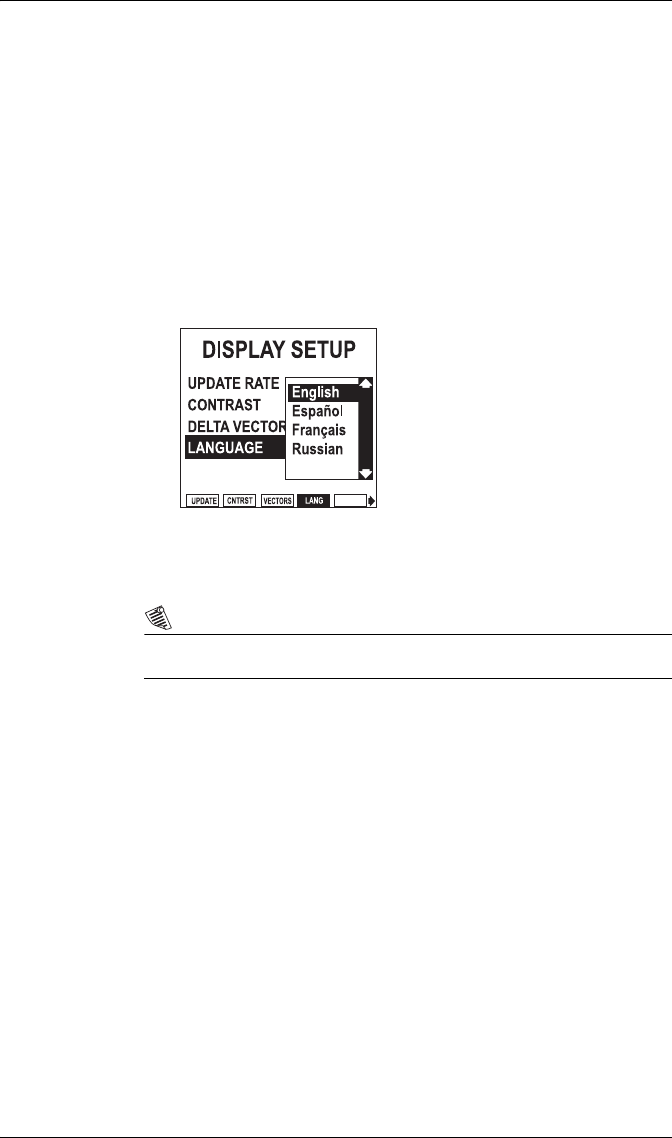
Selecting the Front Panel Language
Meters are shipped with English as the default front panel language.
To select another language:
1. Press PROG/SELECT and the right arrow buttons, hold for two seconds
then release.
2. Scroll through the language list and select the language you want.
3. Press PROG/SELECT to confirm.
You can also access this setting via the Display Setup menu.
NOTE
The meter only communicates to software in English.

PowerLogic ION7550 / ION7650 Installation Guide
20 © 2007 Schneider Electric. All rights reserved.
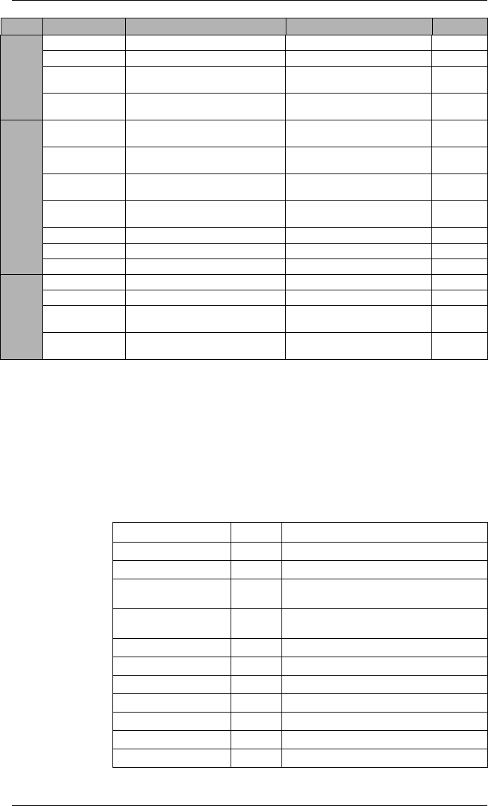
Front Panel Setup Menu Settings
The following table lists all settings that can be configured via the front panel.
Menu Setting Description Range (Values) Default
BASIC SETUP
VOLTS MODE The power system’s configuration –
WYE, DELTA, etc.
4W-WYE, DELTA, 3W-WYE,
SINGLE, DEMO 4W-WYE
PT PRIMARY The Potential Transformer’s primary
winding voltage rating 1 to 999,999.99 120.00
PT SECONDARY The Potential Transformer’s
secondary winding voltage rating 1 to 999,999.99 120.00
CT PRIMARY The Current Transformer’s primary
winding current rating 1 to 999,999.99 5.00
CT SECONDARY The Current Transformer’s
secondary winding current rating 1 to 999,999.99 5.00
V4 PRIMARY The Potential Transformer’s primary
winding voltage rating on V4 1 to 999,999.99 120.00
V4 SECONDARY
The Potential Transformer’s
secondary winding voltage rating
on V4
1 to 999,999.99 120.00
I4 PRIMARY The Current Transformer’s primary
winding current rating on I4 1 to 999,999.99 5.00
I4 SECONDARY
The Current Transformer’s
secondary winding current rating
on I4
1 to 999,999.99 5.00
I5 PRIMARY The Current Transformer’s primary
winding current rating on I5 1 to 999,999.99 5.00
I5 SECONDARY
The Current Transformer’s
secondary winding current rating
on I5
1 to 999,999.99 5.00
V NOMINAL The V1, V2 and V3 nominal voltage
used for harmonics calculations 1.000 to 999,999.000 120.00
V4 NOMINAL The V4 nominal voltage used for
harmonics calculations 1.000 to 999,999.000 120.00
Va POLARITY The polarity of the Potential
Transformer on Va Normal or Inverted Normal
Vb POLARITY The polarity of the Potential
Transformer on Vb Normal or Inverted Normal
Vc POLARITY The polarity of the Potential
Transformer on Vc Normal or Inverted Normal
V4 POLARITY The polarity of the Potential
Transformer on V4 Normal or Inverted Normal
Ia POLARITY The polarity of the Current
Transformer on Ia Normal or Inverted Normal
Ib POLARITY The polarity of the Current
Transformer on Ib Normal or Inverted Normal
Ic POLARITY The polarity of the Current
Transformer on Ic Normal or Inverted Normal
I4 POLARITY The polarity of the Current
Transformer on I4 Normal or Inverted Normal
I5 POLARITY The polarity of the Current
Transformer on I5 Normal or Inverted Normal
CURRENT PROBE
TYPE
The type of current probes being
used with the meter
Factory Default, User Defined 1,
or User Defined 2
Factory
Default

PowerLogic ION7550 / ION7650 Installation Guide
© 2007 Schneider Electric. All rights reserved. 21
COM1 SETUP
PROTOCOL The communications protocol
ION, Modbus RTU, Modbus
Master, DNP V3.00,
GPS:Truetime/Datum,GPS:
Arbiter, GPS:Arbiter-Vorne,
Factory, Ethergate, ModemGate
ION
BAUD RATE The data rate, in bits per second 3001, 1200, 2400, 4800, 9600,
19200, 38400, 57600, 115200 19,200
TRAN DELAY The transmit delay in seconds 0 to 1 0.010
UNIT ID Every meter on an RS-485 network
must have a unique Unit ID number 1 to 9999 From serial
number2
SERIAL PORT Parity and stop bits for the port 8N1, 8N2, 8E1, 8E2, 8O1, 8O2 8N1
MODE Hardware mode for the port RS232 or RS485 RS232
FLOW CONTROL Specifies the handshake mode
when COM1 is set to RS232 RTS + DELAY or RTS/CTS RTS +
DELAY
RS485 BIAS Turns on biasing when Mastering
on the RS-485 bus ON or OFF OFF
COM2 SETUP
PROTOCOL The communications protocol See COM1 protocol ION
BAUD RATE The data rate, in bits per second 3001, 1200, 2400, 4800, 9600,
19200, 38400, 57600, 115200 19,200
TRAN DELAY The transmit delay in seconds 0 to 1 0.010
UNIT ID Every meter on an RS-485 network
must have a unique Unit ID number 1 to 9999 101
SERIAL PORT Parity and stop bits for the port 8N1, 8N2, 8E1, 8E2, 8O1, 8O2 8N1
RS485 BIAS Turns on biasing when Mastering
on the RS-485 bus ON or OFF OFF
COM3 SETUP
PROTOCOL The communications protocol
ION, Modbus RTU, Modbus
Master, DNP V3.00,
GPS:Truetime/Datum,GPS:
Arbiter, GPS:Arbiter-Vorne,
Factory
ION
BAUD RATE The data rate, in bits per second 3001, 1200, 2400, 4800, 9600,
19200, 38400, 57600, 115200 19,200
TRAN DELAY The transmit delay in seconds 0 to 1 0.010
UNIT ID Every meter on an RS-485 network
must have a unique Unit ID number 1 to 9999 102
ANSWER HR
RINGS
The number of rings during defined
answer hours 0 to 255 1
NON-ANSWER
HR RINGS
The number of rings during defined
non-answer hours 0 to 255 5
COM4 SETUP
PROTOCOL The communications protocol ION, Modbus RTU, DNP V3.00,
Factory ION
BAUD RATE The data rate, in bits per second 1200, 2400, 4800, 9600,
19200 9600
TRAN DELAY The transmit delay in seconds 0 to 1 0.010
UNIT ID Every meter on an RS-485 network
must have a unique Unit ID number 1 to 9999 103
SERIAL PORT Parity and stop bits for the port 8N1, 8N2, 8E1, 8E2, 8O1, 8O2 8N1
Menu Setting Description Range (Values) Default

PowerLogic ION7550 / ION7650 Installation Guide
22 © 2007 Schneider Electric. All rights reserved.
NETWORK SETUP
IP ADDRESS Sets the IP address for the meter 000.000.000.000 to
999.999.999.999 varies3
SUBNET MASK Used if subnetting applies to your
network
000.000.000.000 to
999.999.999.999 255.240.0.0
GATEWAY Used in multiple network
configurations
000.000.000.000 to
999.999.999.999 0.0.0.0
DNS PRIMARY
Sets the address for the primary
DNS Server that is configured to
resolve domain names
000.000.000.000 to
999.999.999.999 none
DNS
SECONDARY
Sets the address for the secondary
DNS Server that is configured to
resolve domain names
000.000.000.000 to
999.999.999.999 none
10/100BT
CONFIG
Sets the BASE-T Ethernet max. link
speed and duplexing
Auto, 10BT half, 10BT full,
100BTX half, 100BTX full Auto
100BFX CONFIG Sets the Fiber Ethernet duplexing Full Duplex or Half Duplex Full Duplex
SNMP SERVER Determines whether SNMP protocol
is enabled on the meter or not Enabled or Disabled Disabled
PQ SETUP
SWELL LIMIT
Specifies the magnitude above
which an input must rise for a swell
to be recorded
100 to 1000 106
SAG LIMIT
Specifies the magnitude below
which an input must fall for a sag to
be recorded
0 to 100 88
CHANGE
CRITERIA
Specifies the amount by which an
input must change during a
disturbance to be considered a new
sub-disturbance
0 to 100 10
NOMINAL
VOLTAGE4
Specifies the nominal voltage of the
power system 0 to 1,000,000 0
EVENT PRIORITY Assigns a priority level to sag/swell
events 0 to 255 200
FORMAT SETUP
DIGIT GROUP Specifies symbols used to delimit
thousands & decimal place holder 1000.0 or 1,000.0 or 1000,0 1000.0
VOLTS DECIMAL Number of decimal places
displayed for voltages 1. to 123456789.XXX 1.XX
CURRNT
DECIMAL
Number of decimal places
displayed for currents 1. to 123456789.XXX 1.XXX
POWER DECIMAL Number of decimal places
displayed for power measurements 1. to 123456789.XXX 1.XXX
MEAS SYMBOL Specifies the convention used for
displaying measurements IEEE or IEC IEEE
PHASE LABEL Specifies how phases are labelled ABC, RST, XYZ, RYB, RWB, 123 ABC
PF SIGN Specifies the power factor sign
convention used IEEE or IEC IEEE
PF SYMBOL Sets how power factor is labelled
(LD = leading/LG = lagging) LD/LG, +/-, CAP/IND LD/LG
DATE FORMAT Specifies how dates are displayed MM/DD/YYYY, DD/MM/YYYY,
YYYY/MM/DD
MM/DD/
YYYY
TIME FORMAT Specifies whether time is displayed
in 12 hour or 24 hour clock format 12 H or 24 H 24 H
DISPLAY DST Specifies whether or not DST is
displayed Ye s o r No Yes
Menu Setting Description Range (Values) Default
PowerLogic ION7550 / ION7650 Installation Guide
© 2007 Schneider Electric. All rights reserved. 23
1A baud rate of 300 bps is only intended for paging applications.
2Serial number = PA-0302B222-01, Unit ID = 2222
3Default IP ADDRESS = 172.16.xxx.xxx, where the last two bytes (decimal)
match the last two bytes of the meter’s MAC address (hex).
4NOMINAL VOLTAGE must be set to your system’s nominal voltage to
activate the meter’s power quality features.
Step 9: Verify Meter Operation
The LEDs on the back of the meter flash during communications.
DISPLAY
SETUP
UPDATE RATE Sets when the display updates 1 to 6 (seconds) 1
CONTRAST Higher numbers are sharper 0 to 9 7
DELTA VECTORS Specifies how vector diagrams are
displayed when in Delta mode System or Instrument System
LANGUAGE Specifies the language used on the
meter’s front panel
English, Spanish, French,
Russian English
TIME SETUP
TZ OFFSET Sets the time zone of the meter’s
location, relative to UTC - 12:00 to +13:00 +00:00
DST OFFSET Sets the daylight savings time offset
of the meter’s location -3:00 to +3:00 +00:00
SYNC SOURCE Sets the port to receive time
synchronization signals
Ethernet, COM1, COM2,
COM3, COM4 COM1
SYNC TYPE Specifies whether time sync signals
are received in local time or UTC Local Time or UTC UTC
CLOCK SOURCE Specifies time sync source Internal, Line Freq or COMM Line Freq
LOCAL DATE Sets the local date Same as Date Format setting
LOCAL TIME Sets the local time
SECURITY
SETUP
PASSWORD Sets the meter password 00000000 to 99999999 00000000
ENABLED Enables or disables meter security Yes or No No
WEB CONFIG Enables or disables web browser
configuration of the meter Enabled or Disabled Enabled
WEB ACTIVE Enables or disables internal web
server on the meter Yes or No Yes
Menu Setting Description Range (Values) Default
LED Color Function
Ethernet 100 (Speed) Green Off = link at 10 Mb, On = link at 100 Mb
Ethernet TX Green Blinking indicates Ethernet transmission
Ethernet RX/LINK Green On = link up, Off = link down
Blinking indicates Ethernet reception
Modem DCD Green Indicates a carrier signal is detected (active
connection to the modem)
Modem RI Green Indicates a ring is detected by the modem
COM3 (Modem) TX Yellow Indicates serial transmission on COM3
COM3 (Modem) RX Yellow Indicates serial reception on COM3
COM2 TX Yellow Indicates serial transmission on COM2
COM2 RX Yellow Indicates serial reception on COM2
COM1 TX Yellow Indicates serial transmission on COM1
COM1 RX Yellow Indicates serial reception on COM1
PowerLogic ION7550 / ION7650 Installation Guide
24 © 2007 Schneider Electric. All rights reserved.
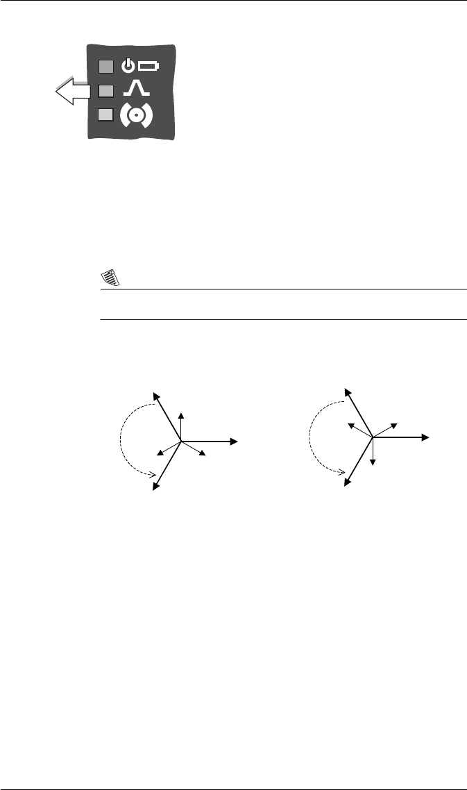
The LEDs on the front panel indicate the following:
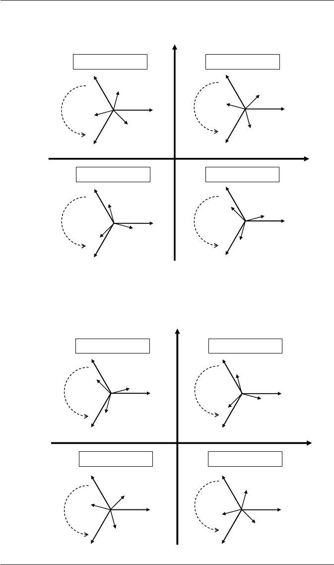
Phasor Diagrams
You can also view the meter’s phasor diagram in real time. Use the Phasor
Viewer available in PowerLogic ION Setup v2.1 and later (free download
from the PowerLogic website) to verify your meter’s wiring. See the ION Setup
online help for details.
NOTE
The following DELTA phasor diagrams are represented in System mode view.
DELTA phasors for UNITY Power Factor (resistive load)
Applicable Volts Mode = DELTA
Top (green) LED indicates the meter is operational. The light
should always remain on when the meter is in service.
Middle (red) LED is a watt-hour pulser. During normal
operations this LED should blink intermittently as the meter
measures power.
Bottom (red) LED is user programmable. It can be used for
Alarm notification. See the
ION7550 / ION7650 User
Guide
for more information.
Watt-hour
pulsing
Front Panel
IA
IC
IB
VAB
VBC
VCA
IA
IC
IB
VAB
VBC
VCA
ABC Rotation
ACB Rotation
PowerLogic ION7550 / ION7650 Installation Guide
© 2007 Schneider Electric. All rights reserved. 25
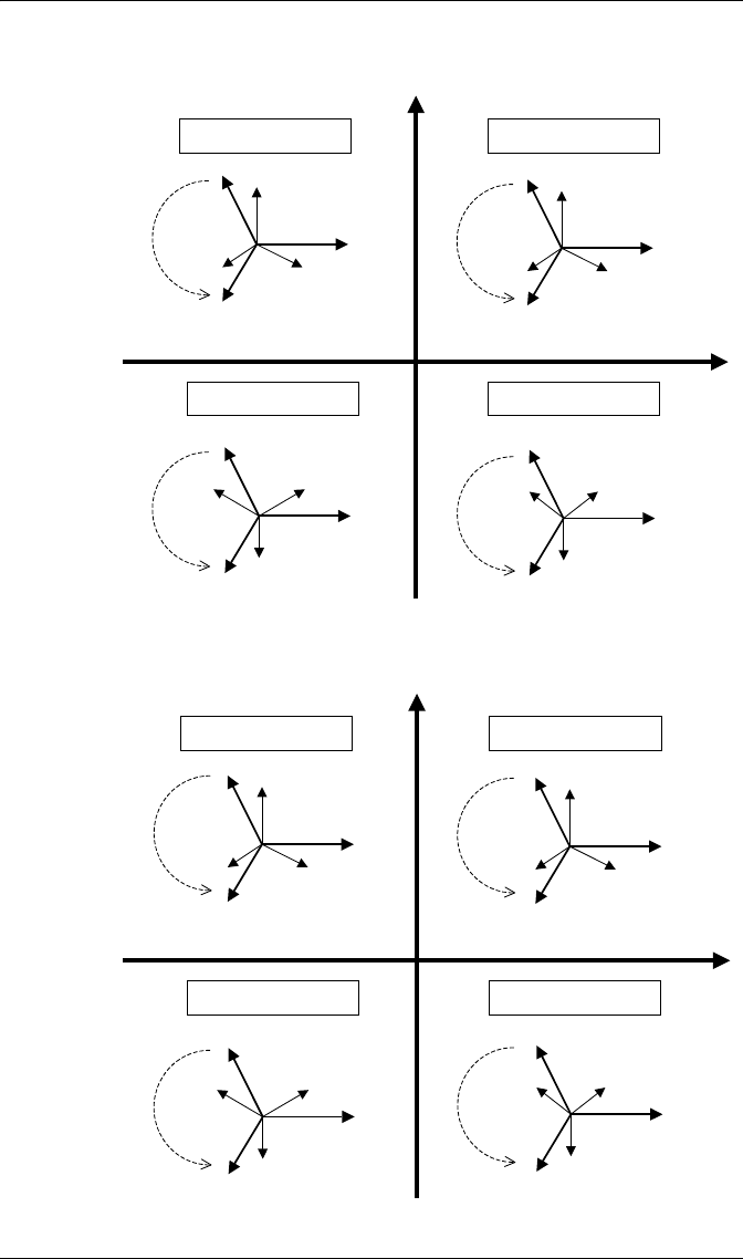
WYE - ABC Rotation
Applicable Volts Mode = 4W-WYE and 3W-WYE
WYE - ACB Rotation
Applicable Volts Mode = 4W-WYE and 3W-WYE
IA
IB
VA
IB
IC
IA IC
VA
IB
VA
IC
VC
VB
IA
VC
VB
IA
IC
IB
VA
VC
VB
VC
VB
Active Powe
r
+k
W
A
ctive Power
-kW
Reactive Power
+kVAR
Reactive Powe
r
-
kVA
R
Q1: Lagging PF (-) Q2: Leading PF (+)
Q4: Leading PF (+) Q3: Lagging PF (-)
Rotation
Rotation
Rotation
Rotation
IC
IA
IB
VA
VB
VC
IA
IB
IC
VA
VB
VC
IA
IB
IC
VA
VB
VC
IA
IC
IB
VA
VB
VC
Rotation
Rotation
Rotation
Rotation
Activ
e Powe
r
+kW
A
ctive Powe
r
-kW
Reactive Power
+kVAR
Reactive Powe
r
-
kVAR
Q1: Lagging PF (-) Q2: Leading PF (+)
Q4: Leading PF (+) Q3: Lagging PF (-)
PowerLogic ION7550 / ION7650 Installation Guide
26 © 2007 Schneider Electric. All rights reserved.
2 Element (3Wire) DELTA - ABC Rotation
Applicable Volts Mode = DELTA
2 Element (3Wire) DELTA - ACB Rotation
Applicable Volts Mode = DELTA
IA
IC
IB
VAB
VCA
VBC
IA
IC
IB
VAB
VCA
VBC
IA
IC
IB
VAB
VCA
VBC
IA
IB
IC
VAB
VCA
VBC
Rotation Rotation
Rotation Rotation
Active Power
+kW
Active Power
-kW
Reactive Power
+kVAR
Reactive Power
-kVAR
Q1: Lagging PF (-)
Q4: Leading PF (+) Q3: Lagging PF (-)
Q2: Leading PF (+)
IA
IB
IC
VCA
VAB
VBC
IA
IB
IC
IA
IB
IC
IA
IC
IB
VCA
VAB
VBC
VCA
VAB
VBC
VAB
VBC
VCA
Rotation Rotation
Rotation Rotation
Active Power
+kW
Active Power
-kW
Reactive Power
+kVAR
Reactive Power
-kVAR
Q4: Leading PF (+) Q3: Lagging PF (-)
Q2: Leading PF (+) Q1: Lagging PF (-)

PowerLogic ION7550 / ION7650 Installation Guide
© 2007 Schneider Electric. All rights reserved. 27
Step 10: View Meter Data
Use the softkeys to select which data to display. Use the left and right arrow
buttons to scroll through the available display screens.
Display Screens
* Additional display screens for ION7650 meters with EN50160 option.
Softkey Contents
V, I , P F Volts, Amps, Power Factor
Volts Volts
Amps Amps
Power Total Power
Energy1 Energy delivered
Demand1 Demand delivered
Pk Dmd1 Peak Demand delivered
V Bar, I Bar, P Bar Voltage, Current and Power Bar Graphs
Summary1, Summary2 Volts/Amps Summary, Power Summary
D Inputs Digital Inputs
DI - I/O Digital I/O on expansion I/O card
D-Output Digital Outputs
Anlg - I/O Analog In and Out
Phasors Phasors
Name Plt Nameplate information
Events Events
Setpoint Setpoint status
Energy2 Energy received
Demand2 Demand received
Pk Dmd2 Peak Demand received
THD Volts and Amps Total Harmonic Distortion
V1 Harm, V2 Harm,... V1, V2, V3, V4 harmonics
I1 Harm, I2 Harm,... I1, I2, I3, I4, I5 harmonics
TOU Time Of Use Active Rate / Season
TOU Egy TOU Energy delivered
TOU Dmd1 & TOU Dmd2 TOU Peak Demand 1 and 2
*PQ Freq Power Quality Power Frequency
*PQ Vmag1 PQ Supply Voltage 1
*PQ Vmag2 PQ Supply Voltage 2
*PQ Flk1 PQ Flicker 1
*PQ Flk2 PQ Flicker 2
*PQ Vdist PQ Voltage Disturbance
*PQ Vunb PQ Voltage Unbalance
*PQ Vhrm1 PQ Voltage Harmonics 1
*PQ Vhrm2 PQ Voltage Harmonics 2
V-Tr e nd, I -Tr e nd, P-Tren d Voltage, Current, Power Trends
PowerLogic ION7550 / ION7650
with WebMeter and MeterM@il
Installation Guide
For further assistance
please contact us at:
Schneider Electric
Power Monitoring and Control
2195 Keating Cross Road
Saanichton, BC
Canada V8M 2A5
Tel: 1-250-652-7100
295 Tech Park Drive, Suite 100
Lavergne, TN 37086
USA
Tel: 1-615-287-3400
Electropole (38 EQI)
31, rue Pierre Mendès France
F - 38050 Grenoble Cédex 9
Tel : + 33 (0) 4 76 57 60 60
Getting technical support:
Contact your local Schneider Electric sales
representative for assistance or go to the
www.powerlogic.com website.
PowerLogic, ION, ION Enterprise, MeterM@il, WebMeter
and Modbus are either trademarks or registered
trademarks of Schneider Electric.
Electrical equipment should be installed, operated,
serviced, and maintained only by qualified personnel.
No responsibility is assumed by Schneider Electric for any
consequences arising out of the use of this material.
70002-0247-10
© 2007 Schneider Electric. All rights reserved.
12/2007
