Schneider Electric WISERCTPM200 Wiser200Amp PanelMeter-CT User Manual Wiser CT Specification v9 CT Final
Schneider Electric Wiser200Amp PanelMeter-CT Wiser CT Specification v9 CT Final
User manual

1
Wiser CT Specification
Contents
1 General Features .................................................................................................................................. 2
1.1 System ........................................................................................................................................... 2
1.2 Metering Measurements ............................................................................................................... 2
1.3 Power Supply ................................................................................................................................. 2
1.4 Memory Backup ............................................................................................................................. 2
1.5 Indicator ........................................................................................................................................ 2
1.6 ZigBee ............................................................................................................................................ 2
2 Environmental Requirements ............................................................................................................... 3
2.1 Environmental Ratings ................................................................................................................... 3
3 Regulatory Requirements ..................................................................................................................... 3
3.1 Agency Approval ............................................................................................................................ 3
4 Mechanical Outline ............................................................................................................................... 3
4.1 Base module .................................................................................................................................. 3
4.2 Current Transformer ...................................................................................................................... 3
5 Electrical ............................................................................................................................................... 4
5.1 Current Transformers (CT) ............................................................................................................. 4
5.2 Switches ........................................................................................................................................ 4
5.3 Terminals ....................................................................................................................................... 4
6 ZigBee Profile ....................................................................................................................................... 5
6.1 Supported Endpoints ..................................................................................................................... 5
6.2 Supported Clusters ........................................................................................................................ 6
7 Application Requirements .................................................................................................................... 8
7.1 Auto Join ....................................................................................................................................... 8
7.2 Power Factor Calculation (Optional) .............................................................................................. 8
2
1 General Features
1.1 System
Metering type: Minimum 2 channel ZigBee SEP 1.1x power meter
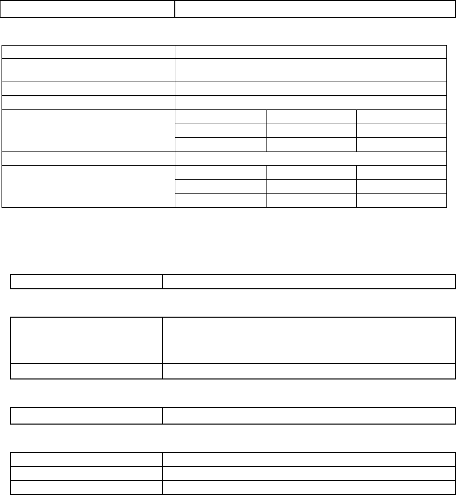
1.2 Metering Measurements
Power measurement (W)
Power measurement reporting rate: Minimum 2 seconds for one channel. Programmable in 1
second step.
Power measurement range: 45 – 48,000W/Channel
Power measurement (W) With calibrated CT clamp on specified port
Power measurement accuracy: PF = 1 0.8 < PF < 1
Power < 100W +/- 3W +/- 4W
Power > 100W +/- 3% +/- 4%
Power measurement (W) With non-calibrated CT clamp
Power measurement accuracy: PF = 1 0.8 < PF < 1
Power < 100W +/- 5W +/- 6W
Power > 100W +/- 5% +/- 6%
• Remark: Only Computime approved CTs can be used.
• Remark: Calibration and testing only be carried with current lower than 100A.
1.3 Power Supply
Power supply 90- 240 VAC
1.4 Memory Backup
Memory backup Non volatile memory backup.
All current summation attributes saved to non volatile memory to
keep cumulative current consumption through power outages.
Data can be backup in every 60 seconds or longer
Flash memory Store firmware for Over The Air (OTA) upgrade
1.5 Indicator
LED indicator Network state indicator, minimum bi-color (red & green)
1.6 ZigBee
ZigBee module ZigBee Smart Energy 1.1x Capable
Frequency 2.4 - 2.48GHZ
Communication range Up to 400m LOS in open site
2405-2480MHz
ZigBee SEP 1.1x power meter

3
2 Environmental Requirements
2.1 Environmental Ratings
Min. Max. Units
Operating Temperature -20 60 °C
Storage Temperature -20 80 °C
Operating Humidity 5 95 %RH
• Indoor use only
3 Regulatory Requirements
3.1 Agency Approval
FCC Regulation
UL/CUL/ETL
RoHS
IEC 61000
4 Mechanical Outline
4.1 Base module
Maximum dimensions: 6”x4.5”x2”
4.2 Current Transformer
The maximum dimensions for the current transformer are show in the drawing below:
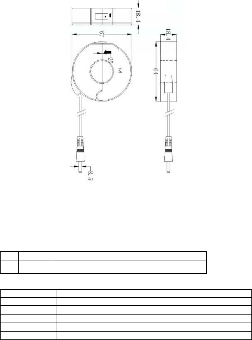
4
5 Electrical
5.1 Current Transformers (CT)
The current transformers must be capable of measuring either consumption or generation.
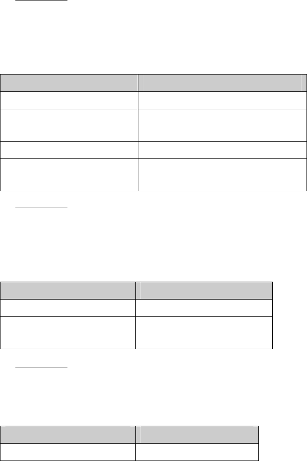
5.2 Switches
No Switch Function
1 PB Push button for manual commissioning/decommissioning
(see section 7.1 for auto join requirements)
5.3 Terminals
AC L1 Line 1 input voltage
AC Neutral AC return
CT Channel 1 Input socket 1 for CT clamp
CT Channel 2 Input socket 2 for CT clamp
CT Channel 3 Input socket 3 for CT clamp
CT Channel 4 Input socket 4 for CT clamp
5
6 ZigBee Profile
The device shall support ZigBee Smart Energy Profile 1.1 at a minimum.
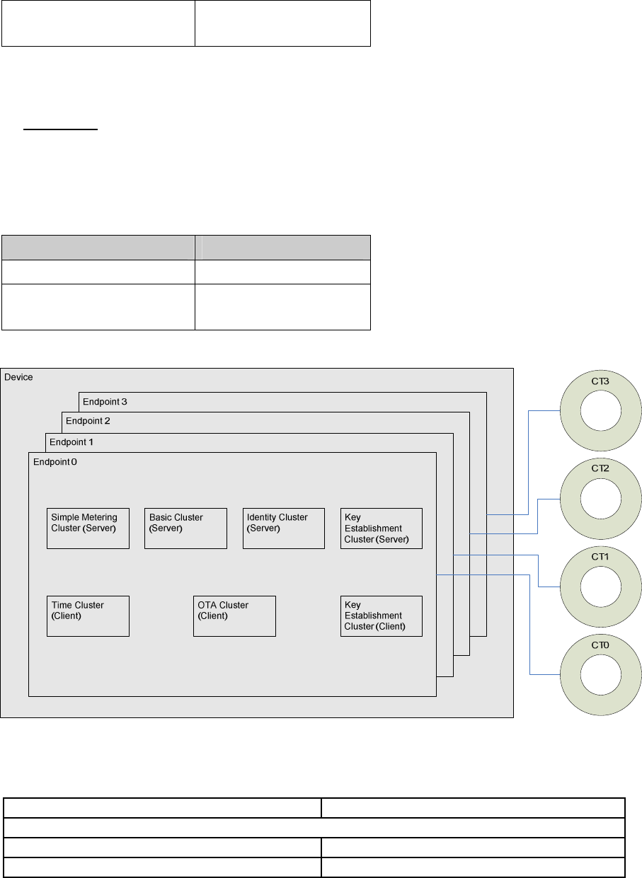
6.1 Supported Endpoints
The device shall provide one endpoint per channel. Each endpoint shall have a Simple Metering cluster
and provide access to the other clusters (i.e. the Basic cluster for Endpoint 4 will actually point to the
Basic cluster for Endpoint 1 to eliminate the need to duplicate and synchronize data).
Any setting on Basic Cluster on any endpoint will be duplicated to all other endpoint
End Point 1:
Profile ID: 0x0109
Device Type/Device ID: 0x0501
Clusters:
End Point 2:
Profile ID: 0x0109
Device Type/Device ID: 0x0501
Clusters:
End Point 3:
Profile ID: 0x0109
Device Type/Device ID: 0x0501
Clusters:
Server Client
Basic Cluster(0x0000) Time Cluster(0x000A)
Simple Meter
Cluster(0x0702)
OTA Cluster(0x0019)
Identify Cluster (0x0003) Key Establishment Cluster(0x0800)
Key Establishment
Cluster(0x0800)
Server Client
Basic Cluster(0x0000)
Simple Meter
Cluster(0x0702)
Server Client
Basic Cluster(0x0000)
6
End Point 4:
Profile ID: 0x0109
Device Type/Device ID: 0x0501
Clusters:
6.2 Supported Clusters
Server side Client side
Common
Basic
Identify
Simple Meter
Cluster(0x0702)
Server Client
Basic Cluster(0x0000)
Simple Meter
Cluster(0x0702)
7
Key Establishment
Time
OTA
SE
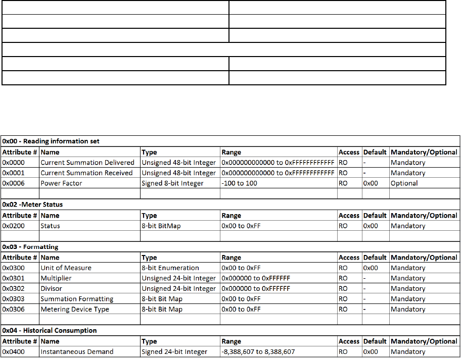
Simple Metering
Key Establishment
Each Simple Metering Cluster shall contain the following attributes:
All other clusters shall adhere to the ZigBee Smart Energy Specification.

8
7 Application Requirements
7.1 Auto Join
The device shall power up initially in a state that beacons the ZigBee Smart Energy network at a
minimum of once per minute to facilitate joining the HAN. This state shall also become active as soon as
the device leaves a HAN. The device shall remain in this state until it joins a HAN.
7.2
Power Factor Calculation (Optional)
The device shall be capable of calculating the power factor and reporting this measurement upon
request.
Disclaimer
Schneider Electric reserves the right to make changes without further notice to any products herein to
improve reliability, function, or design. Schneider Electric does not assume any liability arising out
of the application or use of any product described herein; neither does it convey any license under its
patent rights, not the rights of others.
FCC Statement
This equipment has been tested and found to comply with the limits for a Class B digital device, pursuant to Part 15 of the FCC Rules.
These limits are designed to provide reasonable protection against harmful interference in a residential installation. This equipment
generates uses and can radiate radio frequency energy and, if not installed and used in accordance with the instructions, may cause
harmful interference to radio communications. However, there is no guarantee that interference will not occur in a particular installation.
If this equipment does cause harmful interference to radio or television reception, which can be determined by turning the equipment off
and on, the user is encouraged to try to correct the interference by one or more of the following measures:
-- Reorient or relocate the receiving antenna.
-- Increase the separation between the equipment and receiver.
-- Connect the equipment into an outlet on a circuit different from that to which the receiver is connected.
-- Consult the dealer or an experienced radio/TV technician for help.
This device complies with part 15 of the FCC Rules. Operation is subject to the following two conditions:
(1) This device may not cause harmful interference, and (2) this device must accept any interference received, including interference that
may cause undesired operation.
Changes or modifications not expressly approved by the party responsible for compliance could void the user's authority to
operate the equipment.
The distance between user and products should be no less than 20cm