Schweitzer Engineering Laboratories 900FT50 SEL-FT50 User Manual FT50 FR12 IM 20170317
Schweitzer Engineering Laboratories, Inc. SEL-FT50 FT50 FR12 IM 20170317
User Manual
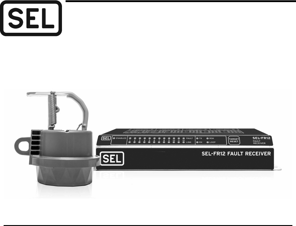
Date Code 20170317 Instruction Manual SEL-FT50/SEL-FR12 Fault Transmitter and Receiver System
Accelerate Tripping, Speed Up Restoration, and
Improve Safety on Distribution Feeders
Major Features and Benefits
The SEL-FT50/SEL-FR12 Fault Transmitter and Receiver System speeds up distribution-protection schemes
by detecting and transmitting distribution feeder fault information to recloser controls or relays. Install the
SEL-FT50 Fault Transmitters on laterals, branches, and the main line to broadcast fault status to one or more
SEL-FR12 Fault Receivers. The SEL-FR12 communicates the fault data through MIRRORED BITS®
communications to a relay or recloser control within 6 ms.
➤Real-Time Distribution Fault Detection. Identify the faulted line segment with fault detection
and low-latency communication while a fault is still active; for use in protection schemes.
➤Enhanced Protection. Make real-time changes to the protection strategy based on information
from the faulted distribution-line segment.
➤Improved Selectivity. Trip a main feeder or branch recloser only when necessary. Avoid
unnecessary entire-feeder outages.
➤Customized Reclosing Strategies. Block or enable reclosing for specific line segments.
➤Improved Power Quality, Reduced System Stress, Limited Equipment Damage, and
Enhanced Safety. Leverage faulted feeder status to better coordinate between protective elements,
leading to faster trip times.
➤Easy Operation. Configure the fault transmitters and receiver without additional software.
➤No Batteries. Power the SEL-FT50 directly from the line because batteries are not necessary.
➤Easy Installation. Install the SEL-FT50 on live lines by using familiar line tools and techniques.
➤Flexible Integration. Install the SEL-FT50/SEL-FR12 system in an existing relay protection system.
SEL-FT50/SEL-FR12
Fault Transmitter and Receiver System
2
SEL-FT50/SEL-FR12 Fault Transmitter and Receiver System Instruction Manual Date Code 20170317
Functional Overview
Functional Overview
The SEL-FT50/SEL-FR12 system consists of as many as twelve SEL-FT50
Fault Transmitters and one SEL-FR12 Fault Receiver. The SEL-FT50 is mounted
on distribution conductors with voltages as high as 38 kV. The SEL-FR12 is
mounted in a recloser control cabinet or in a substation control house.
When one or more SEL-FT50 Fault Transmitters detect a fault, they send a
wireless signal to the SEL-FR12. The SEL-FR12 transfers the received signal
to the recloser control or relay via MIRRORED BITS communications in as little
as 6 ms. The recloser control uses the fault information to make protection or
relay decisions.
To monitor the health of the system, the SEL-FT50 Fault Transmitters
periodically send communication link-check messages to the SEL-FR12 to
indicate their status.
System Overview
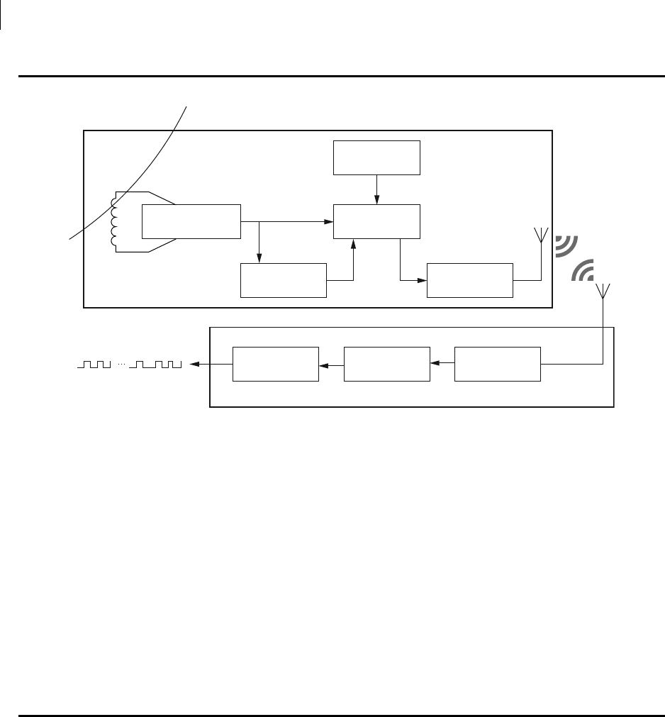
Figure 1 provides an overview of the SEL-FT50/SEL-FR12 system and
illustrates how to apply it across a distribution power system.
Serial Port MIRRORED BITS
Encoder
12-Channel
Receiver
SEL-FR12 Fault Receiver
Receive
MIRRORED BITS Output
Overhead Conductor
SEL-FT50 Fault Transmitter
Signal and
Energy Harvest
Fault
Sense
Link-Check
Timer
Power
Circuit
Radio
Transmit
3
Date Code 20170317 Instruction Manual SEL-FT50/SEL-FR12 Fault Transmitter and Receiver System
System Overview
Figure 1 SEL-FT50/SEL-FR12 System
The SEL-FT50/SEL-FR12 system components are easy to use, and they
contain many powerful and innovative features. Use programmable logic in
the SEL-651R or in connected relays to incorporate the new protection
capabilities and achieve the benefits shown in Figure 1.
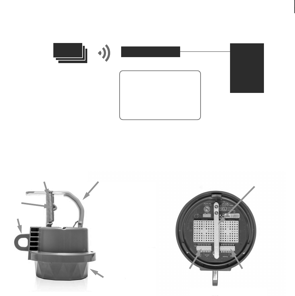
Figure 2 SEL-FT50 Overview
Each SEL-FT50 mounts onto and monitors the line current on one phase.
When a fault occurs, the SEL-FT50 transmits a high-speed wireless signal to
influence protection decisions. Control (DIP) switches inside the transmitter
allow easy selection of unit and Network IDs. No batteries are needed because
the SEL-FT50 is powered by the line current.
Protective Device
SEL-651R
SEL-FR12
SEL-FT50
M
IRRORED
B
ITS
Distribution
System
Collection Protection
Logic
• Collect wireless
signals simultaneously
from as many as 12
fault transmitters
• Monitor as many as 4
three-phase branches
SEL-FT-50/SEL-FR12
System Benefits
• Speed up protection
• Improve power quality
• Protect equipment
• Enhance safety
Hot stick loop
Current transformer
Twistlock housing
for setting access
Omnidirectional antenna for
the radio transmitter
Spring for secure installation
Conductor stop
Left control (DIP)
switch bank
SW 1–4 Unit ID
SW 5–8 Network ID
Right control (DIP)
switch bank
SW 6–8 fault pickup
4
SEL-FT50/SEL-FR12 Fault Transmitter and Receiver System Instruction Manual Date Code 20170317
System Overview
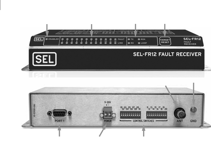
Figure 3 SEL-FR12 Overview
The SEL-FR12 collects wireless signals simultaneously from as many as 12
SEL-FT50 Fault Transmitters (enough for 4 three-phase installations). The
SEL-FR12 reports faults to a relay or recloser control in less than 6 ms via
MIRRORED BITS. The SEL-FR12 HMI contains 29 LEDs and 1 pushbutton, as
shown in Figure 3.
➤The ENABLED LED illuminates green when the SEL-FR12 is
turned on and operational.
➤The 12 FAULT LEDs (red, one per Unit ID) illuminate after the
SEL-FR12 receives a Fault message from the associated
SEL-FT50. These LEDs have a latching behavior so that once
set, they remain on until reset by the TARGET RESET pushbutton
or via MIRRORED BITS command.
➤The 12 LINK LEDs (green, one per Unit ID) have a tristate
operation:
➢LINK LEDs are initially off when the SEL-FR12 is
turned on or after it receives a clear link status
command via MIRRORED BITS.
➢LINK LEDs illuminate when the SEL-FR12 receives
consecutive Link messages or one Fault message from
the associated SEL-FT50. These LEDs have a delayed
dropout behavior. Once illuminated, they remain
illuminated as long as Link signals are periodically
received.
➢LINK LEDs begin to flash after one minute elapses
without receipt of a Link message for the associated
Unit ID. When Link or Fault signals resume, the LINK
LED stops flashing and stays illuminated once again.
ENABLED
LED
FAULT and LINK
status LEDs
MIRRORED BITS
status LEDs
TARGET RESET
pushbutton
Serial port
(DB-9 connector)
Power supply
input (9–30 Vdc)
Control (DIP) switches to select:
• Network ID—SW 1–4
• Baud rate—SW 5–6
• MIRRORED BITS TX and RX ID—SW 7–10
• Near/distant SEL-FT50—SW 11–14
Radio antenna
BNC connector
Grounding lug
5
Date Code 20170317 Instruction Manual SEL-FT50/SEL-FR12 Fault Transmitter and Receiver System
Application Examples
➤The ROK, TX, RX (green), and LOOP (red) LEDs indicate
MIRRORED BITS status and activity. The ROK LED illuminates
when MIRRORED BITS data exchange is successful.
➤The TARGET RESET pushbutton resets the FAULT LEDs. Press and
hold the pushbutton to illuminate all HMI LEDs (lamp test
function).
Application Examples
Collect Fault
Information From
Remote Branches
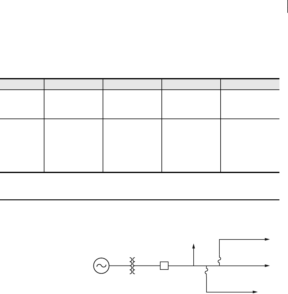
A traditional recloser control or substation circuit breaker must be coordinated
with the other protective devices on a distribution feeder, including fuses on
downstream line segments. On the sample feeder in Figure 4, the recloser
control or substation relay cannot distinguish one segment from another.
Figure 4 Typical Recloser Visibility
The SEL-FT50/SEL-FR12 system offers increased visibility to a recloser
control by providing fault status from locations as far away as two miles.
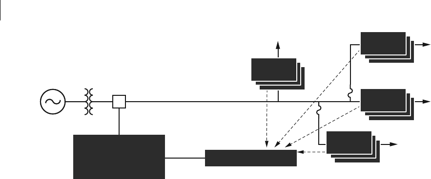
Figure 5 illustrates how this allows the recloser control to see faults on
individual branches, including locations where it is not economically feasible
to install a relay or recloser. Each SEL-FT50 label in Figure 5 represents three
SEL-FT50 Fault Transmitters, one per phase.
Table 1 Target and Status LED Definitions
LED (Color) Off Flashing On Reset Methods
FAULT (red) target No fault signal has been
received from the
corresponding Unit ID
since the last reset.
Not applicable. The SEL-FR12 received a
fault signal from the cor-
responding Unit ID since
the last reset.
Manual—resets via the
TARGET RESET pushbutton.
Remote—resets via MIR-
RORED BITS.
LINK (green) status The SEL-FR12 has not
detected an SEL-FT50
with the corresponding
Unit ID since initializa-
tion.
This learning feature
keeps unused LINK LEDs
turned off.
The SEL-FR12 is not
presently receiving sig-
nals from the previously
learned Unit ID, indicat-
ing that an SEL-FT50 is
not harvesting energy
during low-current condi-
tions or an outage.
The SEL-FR12 has
received signals from the
corresponding Unit ID
within the last minute,
indicating that the
SEL-FT50 is receiving
minimum radio link active
current.
Automatic—learning
mode resets automatically
after the SEL-FR12 turns
on.
Remote—resets via MIR-
RORED BITS.
R?
?
??
6
SEL-FT50/SEL-FR12 Fault Transmitter and Receiver System Instruction Manual Date Code 20170317
Application Examples
Figure 5 Recloser Communication With Fault Transmitters
Each SEL-FT50 monitors line current and instantly transmits a wireless signal
when an overcurrent (fault) condition occurs. The companion SEL-FR12
receives and aggregates fault data from as many as 12 SEL-FT50 Fault
Transmitters. Upon detecting a fault indication signal, the SEL-FR12
communicates the fault information to the host SEL-651R recloser control, or
other SEL protective relay, by using MIRRORED BITS communications.
The SEL-FT50/SEL-FR12 system allows the protective relay or recloser
control to make intelligent decisions by using high-speed fault information
from remote locations.
Improve Fuse
Coordination
In a radial distribution system, there are two main schemes that control fuse
coordination: fuse-saving and fuse-blowing (also called trip-saving). Each of
these schemes has shortcomings that you can address with the
SEL-FT50/SEL-FR12 system.
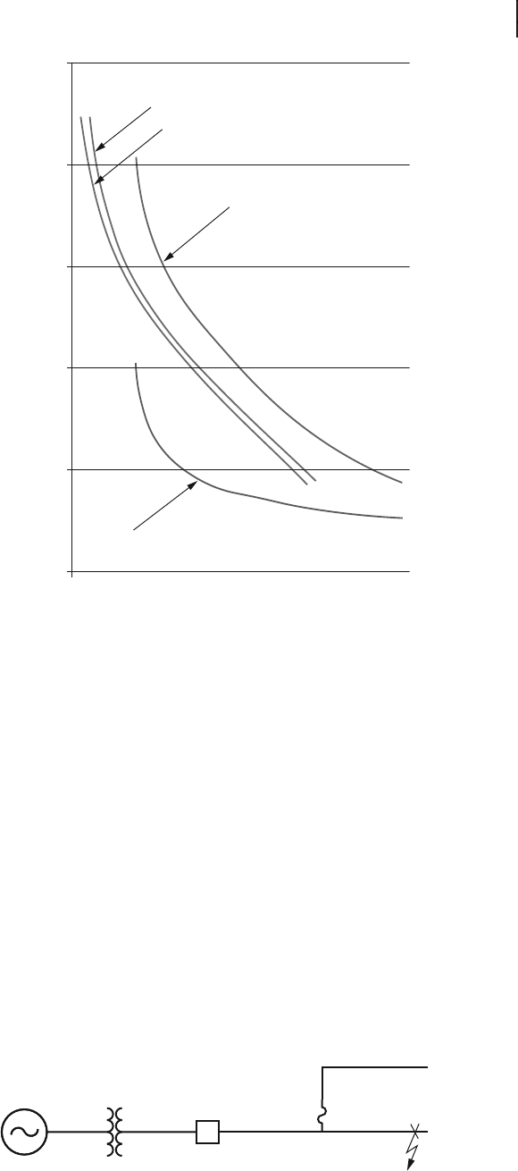
Figure 6 gives a representation of a typical time-overcurrent coordination
graph.
R
Wireless
SEL-FT50
SEL-FT50
SEL-FT50
SEL-FT50
SEL-FR12
SEL-651R-2
7
Date Code 20170317 Instruction Manual SEL-FT50/SEL-FR12 Fault Transmitter and Receiver System
Application Examples
Figure 6 Example Time-Overcurrent Element Coordination
Fuse-Blowing Scheme
Shortcomings
For a radial distribution system, the goal of the fuse-blowing scheme is to
minimize the number of customers exposed to an interruption. The scheme
accomplishes this by allowing a fuse to clear a given fault. The recloser only
trips for faults that are not protected by a fuse. This scheme is sometimes
called a trip-saving or fuse-blowing scheme because the recloser only trips
when absolutely necessary.
Refer to Figure 6 for the recloser control time-overcurrent element slow curve
(shown in red). This curve must coordinate with the highest-rated fuse size
present on the system, which is shown in green. An intentional coordination
margin allows for prefault load and variances in fuse construction.
For faults on sections of the feeder that are not fuse-protected, the recloser
must still implement this intentional coordination margin. The recloser control
cannot determine which downstream branch the fault is on and assumes that
the fault will be cleared by a fuse. Figure 7 shows an example of a main line
feeder and a fused lateral without a fuse. For a fault on the main line, the
recloser control will wait before using the slow curve to clear the fault (see
Figure 6). For a fault on the main line, the recloser control delays tripping
unnecessarily because there is no fuse present.
Figure 7 Fault on Unfused Tap
Recloser Control
Fast Curve
Recloser Control
Slow Curve
Fuse-Melting Curve
Fuse-Clearing Curve
0.01
0.1
1
10
100
100
Current (A)
1,000
1,000
Time (s)
R
8
SEL-FT50/SEL-FR12 Fault Transmitter and Receiver System Instruction Manual Date Code 20170317
Application Examples
Improve Fuse-Blowing
Schemes With the
Fault Transmitter and
Receiver System
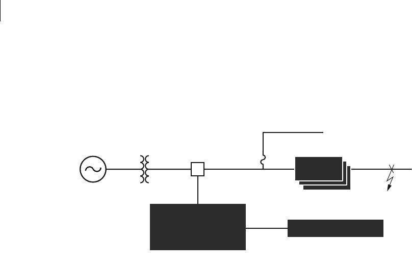
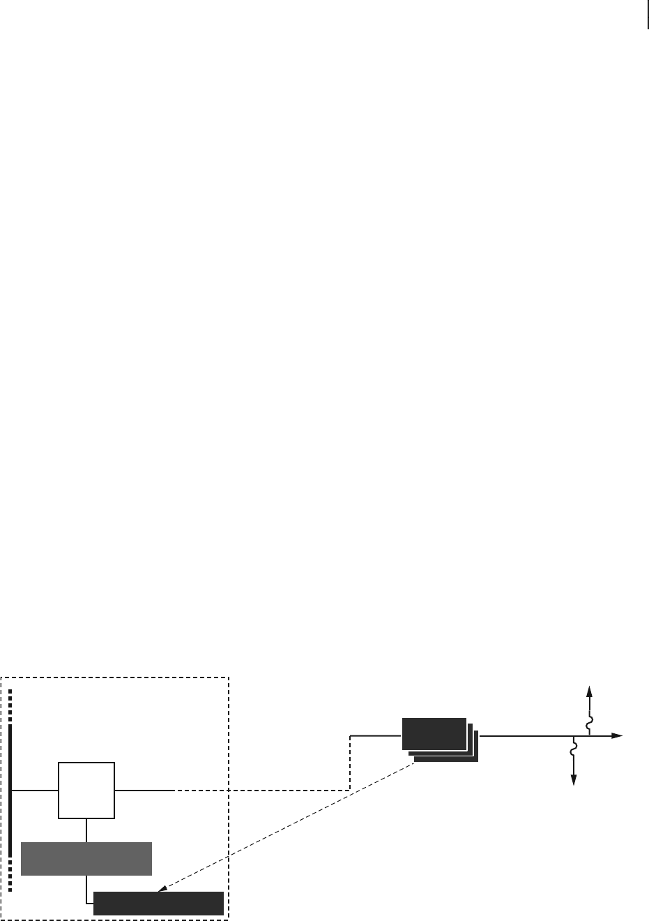
With the SEL-FT50/SEL-FR12 system installed as shown in Figure 8, the
recloser control receives an indication whenever a fault is on the unfused
branch. With this information, if a fault occurs on the unfused line section, the
recloser control can trip instantaneously instead of waiting for the fuse delay.
In Figure 8, the unfused tap is monitored by a set of SEL-FT50 Fault
Transmitters (one for each phase), one SEL-FR12, and one SEL-651R. The
SEL-FR12 is connected to the SEL-651R via a serial port.
Figure 8 SEL-FT50 on Unfused Tap
When using the SEL-FT50/SEL-FR12 system, the SEL-651R knows when a
fault occurs on the unfused tap because one or more of the SEL-FT50 Fault
Transmitters detect the fault current and send the fault status to the SEL-FR12,
which then conveys the information to the recloser control.
The SEL-651R settings replace or modify the curve behavior while the fault is
happening. In the example fault shown in Figure 8, the recloser control
enables the recloser control fast curve (see Figure 6). Compare this to when a
fault is on the same unfused line section but the recloser control does not know
it. The recloser trips after a delay. Based on the coordination curves in
Figure 6, for a 1000 A fault, using the SEL-FT50/SEL-FR12 system to trip on
the fast curve instead of the slow curve reduces the fault clearing time by
400 ms.
Fuse-Saving
Combined With Fuse-
Blowing Schemes
The fundamental choice in distribution-line protection is between fuse-saving
and fuse-blowing. For a given fault, designers either favor blowing fuses and
disrupting as few customers as possible, or tripping the recloser and
interrupting the fault without blowing any fuses. Each method has its
advantages, but the protection planner has to pick one or the other.
Using the SEL-FT50/SEL-FR12 system, design smart protection that switches
from fuse-saving to fuse-blowing, or vice versa without interruption. You get
the fuse-saving or fuse-blowing benefits you want while eliminating any
drawbacks.
The following two example applications show how a single protective zone
using the SEL-FT50/SEL-FR12 system allows both fuse-saving and fuse-
blowing schemes in service.
Example 1: Switchover Without Interruption From a Fuse-Blowing
Scheme to a Fuse-Saving Scheme
In this switchover scheme, utilities have the option to tailor protection for
specific line segments with different characteristics. If the SEL-FT50 declares
that a fault is present on a candidate line section, the scheme enables fuse-
saving while the fault is in progress. For other faulted line segments, the fuse-
blowing scheme works as intended.
R
SEL-FR12
SEL-651R-2
When the fault is on the unfused branch, the recloser trips without fuse-coordination delay.
SEL-FT50
9
Date Code 20170317 Instruction Manual SEL-FT50/SEL-FR12 Fault Transmitter and Receiver System
Application Examples
Example 2: Switchover Without Interruption From a Fuse-Saving
Scheme to a Fuse-Blowing Scheme
In this switchover scheme, the SEL-FT50/SEL-FR12 system is used to
indicate which line section contains a fault. However, the fuse-saving scheme
is the default operating mode. When the SEL-FT50 declares that a fault is
present on a candidate line section, the scheme enables fuse-blowing while the
fault is in progress. For other faulted line segments, the fuse-saving scheme
works as intended.
Improve Feeder Cable
First-Span Protection
The SEL-FT50/SEL-FR12 system improves first-span feeder cable protection.
Feeder cables are often used for substation egress, eliminating overhead line
clutter and improving working safety. These feeder cables radiate from a
substation, continuing for a few feet to one mile. These cables are usually
terminated on a riser pole and then connected to the overhead conductors.
To protect cable sections, some utilities use instantaneous overcurrent
elements with pickup levels set to cover the entire cable length, plus some
margin that overreaches onto a portion of the overhead line. In these
applications, a high-current fault causes an instantaneous trip with no
reclosing permitted.
While this approach protects equipment, it also often causes an unnecessary
permanent outage when the fault is on the portion of the overhead line where
available fault levels are still very high. The majority of overhead faults are
caused by temporary events and are far more likely to occur than underground
faults. By not reclosing for close-in overhead faults, the entire feeder suffers a
permanent outage that could have been avoided.
To improve the first-span feeder cable protection, use a set of three SEL-FT50
Fault Transmitters to monitor the first span of overhead line, as shown in
Figure 9. When an overhead fault occurs, the relay instantaneous element trips
the recloser or feeder breaker, but reclosing is allowed when the SEL-FT50
signals that the fault is on the overhead portion of the feeder. This simple
modification of an existing scheme improves system availability. This
application extends to any line that transitions between overhead and
underground lines. Knowing whether a fault is on an overhead or underground
section of a feeder helps when coordinating reclosing and protection schemes.
Figure 9 Feeder Cable Egress Protection With Enhancements
SEL-FR12
Relay
Breaker
Substation bus
Substation
Underground
feeder cable
Wireless
Riser pole Overhead conductor
SEL-FT50
10
SEL-FT50/SEL-FR12 Fault Transmitter and Receiver System Instruction Manual Date Code 20170317
Safety Information
Tripping the Right
Recloser Faster
You can protect a distribution feeder with multiple reclosers. In a radial
system, to optimize selectivity, users want the recloser closest to the fault to
operate for that fault. For this reason, reclosers at the end of the distribution
line are set to trip first and the close-in reclosers are set to delay their tripping.
Figure 10 shows a fault in Zone R1. In a conventional protection design,
assuming the reclosers use a fuse-blowing scheme, R1 clears this fault, but
only after it gives Zones R2, R3, and R4 a chance to operate. This situation
results in a long fault duration that stresses the system and impacts the power
quality on other substation loads.
Figure 10 Radial Distribution Line With Multiple Reclosers
Fix this problem by using an SEL-FT50/SEL-FR12 system. In Figure 10, the
SEL-FT50 detects the fault and immediately transmits the information to the
SEL-FR12, which then sends this information to the recloser control at R1.
Because R1 knows that the fault is in its zone, it trips without waiting for the
downstream reclosers, avoiding the unnecessary coordination delay.
Safety Information
Regulatory
Information
The SEL-FT50 is approved for use only with specific output power
configurations that have been tested and approved. Modifications to the
SEL-FT50, the SEL-FR12, the antenna system, and the power output that
have not been explicitly specified by the manufacturer are not permitted and
may render the radio noncompliant with applicable regulatory authorities. The
radio equipment described in this manual emits radio frequency energy.
Professional installation is required.
This equipment has been tested and found to comply with the limits for
Class A digital devices, pursuant to FCC Part 15 Rules. These limits are
designed to provide reasonable protection against harmful interference when
the equipment is operated in a commercial environment. This equipment
generates, uses, and radiates radio frequency energy, and if not installed and
used in accordance with the instruction manual, may cause harmful
interference to radio communication. Operation of this equipment in a
residential environment is likely to cause harmful interference, in which case
the user will be required to correct the interference at his/her own expense.
R1
SEL-FR12
SEL-651R-2
R2 R3 R4
SEL-FT50
CAUTION
Although the power level is low,
concentrated energy from a
directional antenna may pose a
health hazard. Do not allow users to
come closer than 23 cm (9 in) to the
transmitter when it is operating.
DANGER
Install fault transmitters and sensors
in accordance with normal safe
operating procedures. These
instructions are not intended to
replace or supersede existing safety
or operating requirements. Only
trained qualified personnel with
knowledge of high voltage safety
should install or operate fault
transmitters.
11
Date Code 20170317 Instruction Manual SEL-FT50/SEL-FR12 Fault Transmitter and Receiver System
Safety Information
Dangers, Warnings,
and Cautions
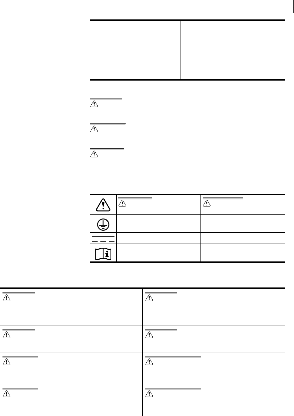
This manual uses three kinds of hazard statements, defined as follows:
Safety Symbols The following symbols apply to this device.
Safety Marks The following statements apply to this device.
This device complies with Industry
Canada license-exempt RSS stan-
dard(s). Operation is subject to the fol-
lowing two conditions: (1) this device
may not cause interference, and (2) this
device must accept any interference,
including interference that may cause
undesired operation of the device.
Le présent appareil est conforme aux CNR
d'Industrie Canada applicables aux appareils
radio exempts de licence. L'exploitation est
autorisée aux deux conditions suivantes :
(1) l'appareil ne doit pas produire de
brouillage ; (2) l'utilisateur de l'appareil doit
accepter tout brouillage radioélectrique subi,
même si le brouillage est susceptible d'en com-
promettre le fonctionnement.
DANGER
Indicates an imminently hazardous situation that, if
not avoided, will result in death or serious injury.
WARNING
Indicates a potentially hazardous situation that, if
not avoided, could result in death or serious injury.
CAUTION
Indicates a potentially hazardous situation that, if
not avoided, may result in minor or moderate injury
or equipment damage.
CAUTION
Refer to accompanying documents.
ATTENTION
Se reporter à la documentation.
Protective earth (ground) Terre de protection
Direct current Courant continu
Instruction manual Manuel d’instructions
DANGER
Disconnect or de-energize all external connections before opening this
device. Contact with hazardous voltages and currents inside this
device can cause electrical shock resulting in injury or death.
DANGER
Débrancher tous les raccordements externes avant d’ouvrir cet
appareil. Tout contact avec des tensions ou courants internes à
l’appareil peut causer un choc électrique pouvant entraîner des
blessures ou la mort.
DANGER
Contact with instrument terminals can cause electrical shock that can
result in injury or death.
DANGER
Tout contact avec les bornes de l’appareil peut causer un choc
électrique pouvant entraîner des blessuers ou la mort.
WARNING
Use of this equipment in a manner other than specified in this manual
can impair operator safety safeguards provided by this equipment.
AVERTISSEMENT
L’utilisation de cet appareil suivant des procédures différentes de
celles indiquées dans ce manuel peut désarmer les dispositifs de
protection d’opérateur normalement actifs sur cet équipement.
WARNING
Have only qualified personnel service this equipment. If you are not
qualified to service this equipment, you can injure yourself or others,
or cause equipment damage.
AVERTISSEMENT
Seules des personnes qualifiées peuvent travailler sur cet appareil. Si
vous n’êtes pas qualifiés pour ce travail, vous pourriez vous blesser
avec d’autres personnes ou endommager l’équipement.
12
SEL-FT50/SEL-FR12 Fault Transmitter and Receiver System Instruction Manual Date Code 20170317
System Installation
System Installation
SEL-FR12 The SEL-FR12 uses two 10-position control (DIP) switches to set the wireless
network identification (Network ID) of the associated SEL-FT50 Fault
Transmitters, the baud rate and addresses for the MIRRORED BITS serial
communications port, and the separate receiver gain values for the SEL-FT50
Fault Transmitters.
The control (DIP) switch assignments are listed on the SEL-FR12 enclosure.
The switch positions are labeled 1 through 20, but only 1 through 14 are used.
Physical Installation
Install the SEL-FR12 first for easier commissioning when you install the
SEL-FT50 Fault Transmitters.
For simplest installation, place the SEL-FR12 inside the recloser control
cabinet, powered by the 12 Vdc auxiliary power supply of the SEL-651R.
However, it can be installed with any device that communicates through
MIRRORED BITS. The SEL-FR12 must be connected to an antenna that is
outside the recloser control cabinet and can connect to a coaxial cable run with
proper grounding and lightning protection devices. The antenna is typically
mounted higher up on the pole in a safe location. The appropriate antenna type
is site-specific. Perform a path study before choosing the antenna.
The SEL-FR12 serial port connects to one of the serial ports of the SEL-651R
that are configured for SEL MIRRORED BITS communications. This
connection allows the SEL-FR12 to share the received fault with the recloser
control. The programmable logic of the recloser control is configured to
incorporate the received data as part of the protection or control decisions.
Installation details differ slightly for SEL-FR12 Fault Receivers placed in
substations.
Refer to the SEL Radios Accessories Guide on the SEL website for a complete
list of radio accessories offered by SEL.
Mounting the SEL-FR12
Use the accessory kit hardware to mount the SEL-FR12 in the recloser control
cabinet. When ordered as an accessory to the SEL-651R, the unit comes pre-
installed without wiring as part of the cabinet.
Chassis Ground and Power Connection
Connect the rear-panel grounding terminal (labeled with the ground symbol)
to a rack frame ground or main station ground for proper safety and
WARNING
Do not perform any procedures or adjustments that this instruction
manual does not describe.
AVERTISSEMENT
Ne pas appliquer une procédure ou un ajustement qui n’est pas décrit
explicitement dans ce manuel d’instruction.
CAUTION
Equipment components are sensitive to electrostatic discharge (ESD).
Undetectable permanent damage can result if you do not use proper
ESD procedures. Ground yourself, your work surface, and this
equipment before removing any cover from this equipment. If your
facility is not equipped to work with these components, contact SEL
about returning this device and related SEL equipment for service.
ATTENTION
Les composants de cet équipement sont sensibles aux décharges
électrostatiques (DES). Des dommages permanents non-décelables
peuvent résulter de l’absence de précautions contre les DES.
Raccordez-vous correctement à la terre, ainsi que la surface de travail
et l’appareil avant d’en retirer un panneau. Si vous n’êtes pas équipés
pour travailler avec ce type de composants, contacter SEL afin de
retourner l’appareil pour un service en usine.

13
Date Code 20170317 Instruction Manual SEL-FT50/SEL-FR12 Fault Transmitter and Receiver System
System Installation
performance. Use 4 mm2 (12 AWG) or heavier wire of less than 2 meters
(6.6 feet) for this connection. Make the ground connection before making the
power connections.
Connect the power harness to a fused 12 V auxiliary power supply terminal on
the SEL-651R, paying attention to polarity.
If possible, turn on the SEL-FR12 and verify that the ENABLED LED
illuminates. Turn it off before continuing.
Connect the Serial Port
Use a short cable, such as the SEL-C272, to connect the serial output of the
SEL-FR12 to the recloser control or relay serial port that has been configured
for MIRRORED BITS operation.
Turn on the SEL-FR12 and verify that the ROK LED illuminates. If ROK does
not assert, check the SEL-FR12 MIRRORED BITS Speed and Address switches
and compare them with the MIRRORED BITS port settings of the host device.
Turn it off before continuing.
Feed Lines
The feed line used with the antenna is important. Use coaxial cables that have
low attenuation and are rated for outdoor use. Keep the feed line as short as
possible to minimize signal loss between the radio and antenna. RG8X or
LMR-400 coaxial cables are preferred. If longer lengths or less cable loss is
desired for the radio link, then you can use a larger cable, such as a 7/8-inch
HELIAX. Table 2 lists the signal losses for the indicated lengths of each cable type.
Antenna System Ground
Antenna system grounding is not included in the scope of this manual. Please
consult a radio systems engineer or other professional for advice on ground-
system design, and read AG2014-36, Radio System Lightning Protection Best
Practices, which can be found on the SEL website. A well-designed system
will minimize equipment damage and risk of electric shock to personnel.
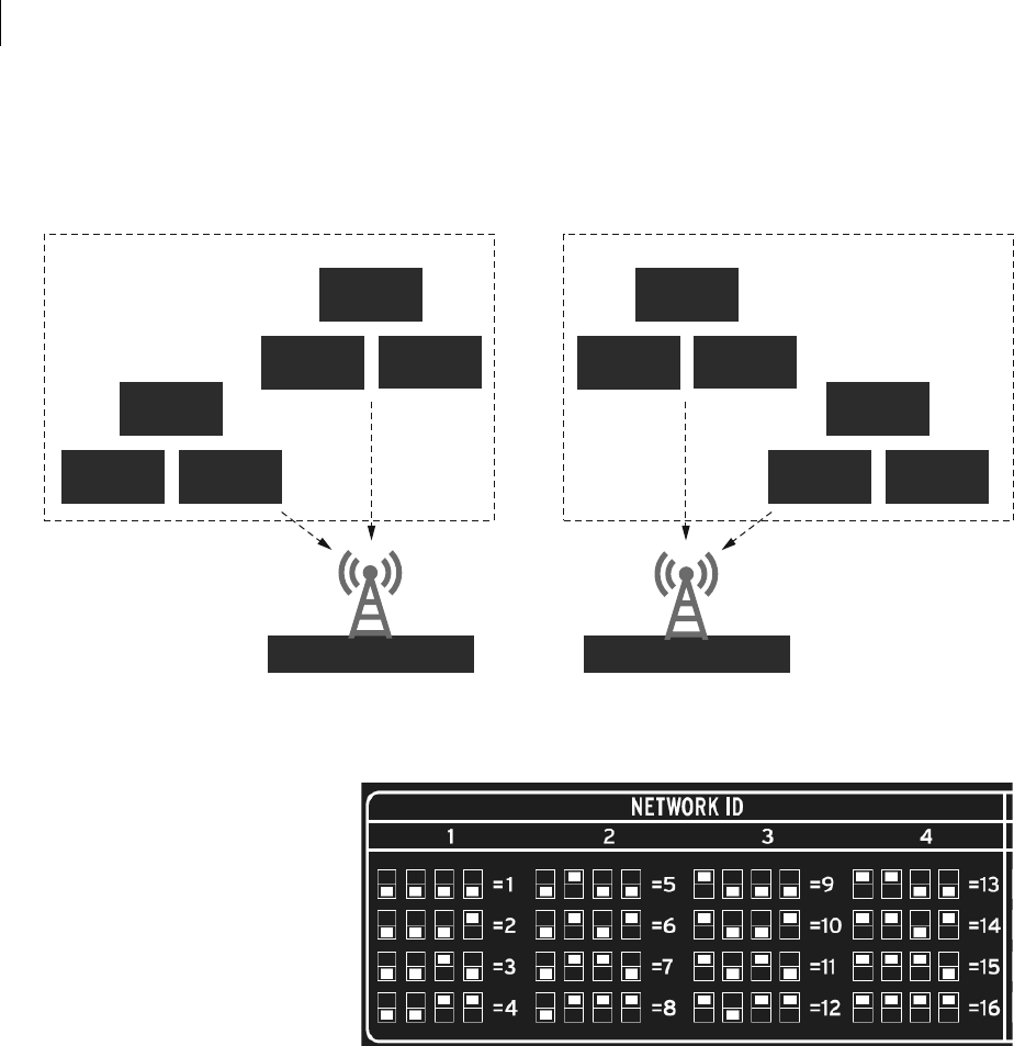
Setting Network ID
To enable multiple wireless fault transmitter and fault receiver systems to
operate in close proximity, both the SEL-FT50 and SEL-FR12 feature a
Network ID selection (1–16). See Figure 11 for an example of two networks.
The SEL-FR12 will only receive transmissions from SEL-FT50 Fault
Transmitters that match its Network ID.
Each SEL-FT50 contain configuration switches to select one of sixteen
network identification numbers. The SEL-FR12 also has Network ID
Table 2 Length vs. Loss in Coaxial Cables at 900 MHz
Cable Type Characteristic
Impedance
3.05 Meters
(10 Feet)
12.24 Meters
(50 Feet)
30.48 Meters
(100 Feet)
91.44 Meters
(300 Feet)
RG-8X
(SEL-C964, SEL-C975)
50 :0.70 dB 3.50 dB 7.0 dB Unacceptable loss
LMR-400
(SEL-C966, SEL-C968)
50 :0.39 dB 1.95 dB 3.90 dB Unacceptable loss
7/8-inch HELIAX
(SEL-C978)
50 :Do not use 0.64 dB 1.28 dB 3.84 dB
14
SEL-FT50/SEL-FR12 Fault Transmitter and Receiver System Instruction Manual Date Code 20170317
System Installation
configuration switches and will only accept received SEL-FT50 messages that
have a matching Network ID.
For example, if three distribution feeders emanate from one substation, each
with their own SEL-FT50/SEL-FR12 system, these systems operate
independently if they have unique Network IDs.
Figure 11 Two-Network Example
Once you have determined the Network ID to be used, set control switches to
the appropriate positions, as shown in Figure 12.
Figure 12 Network ID Switch Selection
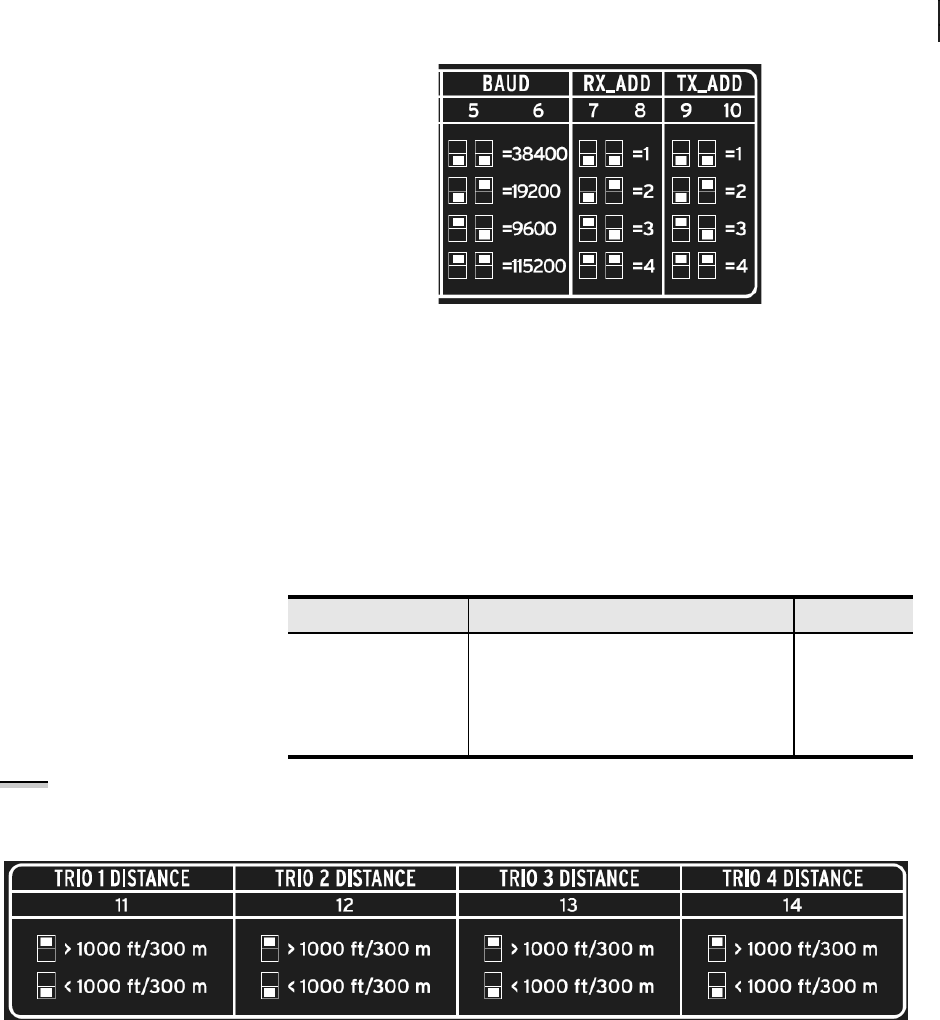
Serial Port Settings
Configure the desired serial port baud rate through use of the control switch
positions.
For best performance, choose the highest speed that matches the available
MIRRORED BITS speed on the connected device.
Set the transmit address (TX_ADD) of the SEL-FR12 to match the receive
address of the connected device. Set the receive address (RX_ADD) of the
SEL-FR12 to match the receive transmit of the connected device. Figure 13
outlines the control switch settings. Do not set the TX and RX addresses of
each device to the same number because the SEL-FR12 detects a loopback
condition when it receives its own transmit address in the MIRRORED BITS
message. When the SEL-FR12 detects loopback, the LOOP LED illuminates
and the ROK LED extinguishes.
SEL-FR12SEL-FR12
SEL-FT50
SEL-FT50
SEL-FT50
SEL-FT50
SEL-FT50
SEL-FT50
SEL-FT50
SEL-FT50
SEL-FT50
SEL-FT50
SEL-FT50
SEL-FT50
Network ID 01 Network ID 04
Network ID 01 Network ID 04
Unique Network IDs
isolate system operation
01
02
03
04
05
06
01
02
03
04
05
06
15
Date Code 20170317 Instruction Manual SEL-FT50/SEL-FR12 Fault Transmitter and Receiver System
System Installation
Figure 13 Serial Port Settings Selection
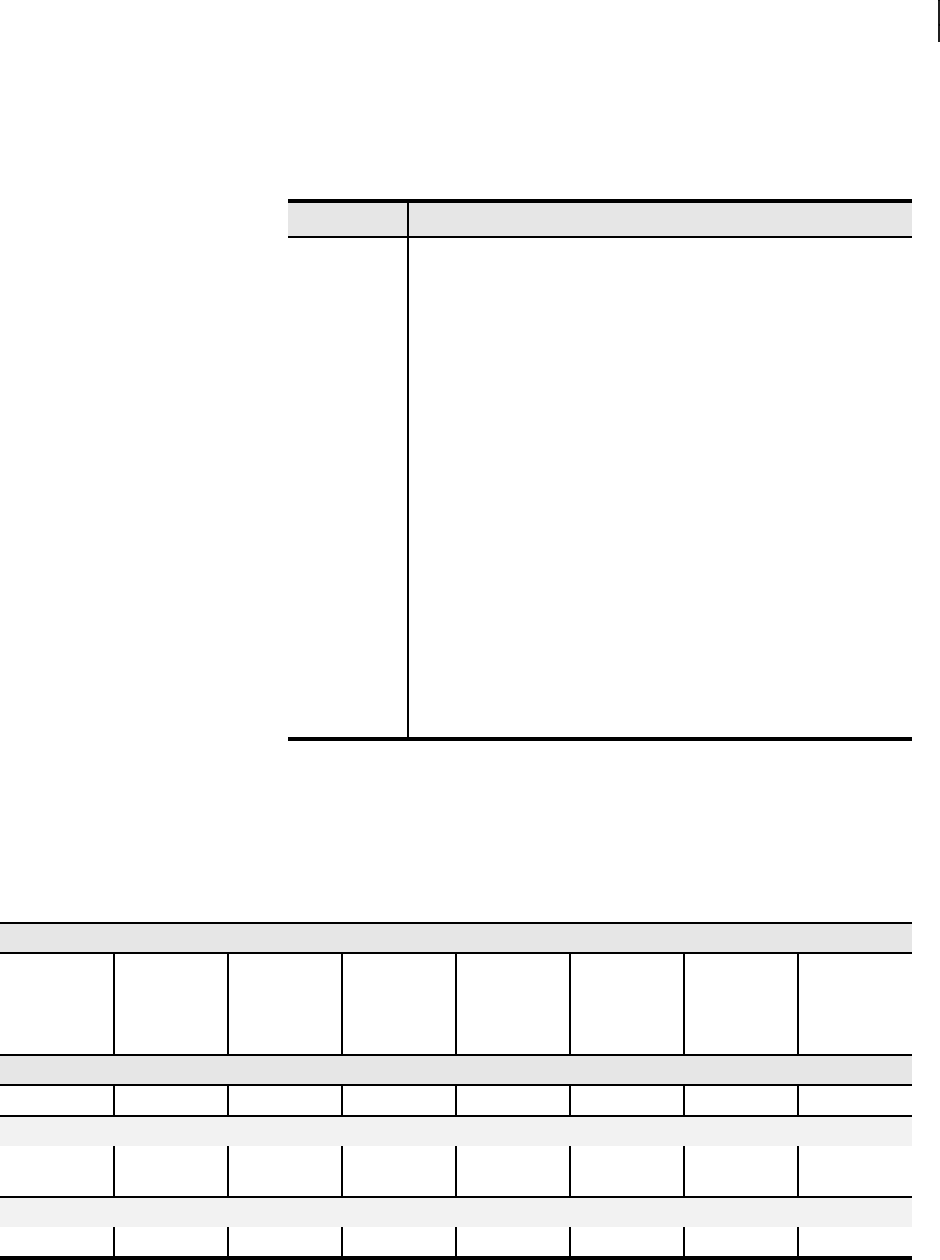
Setting Near/Distant SEL-FT50
For three-phase installations, the SEL-FT50 Fault Transmitters are installed in
groups of three, and the received signal strength from all members of a trio is
identical. The received signal strength between multiple trios is usually
different because of path differences. To accommodate the range of reception
signal strengths, an attenuation setting is provided for each trio. See Table 3
for trio assignments.
NOTE: There is no transmitter power
adjustment selection in the SEL-FT50. The appropriate attenuation setting for each trio is based on the distance
between the trio and the SEL-FR12.
Figure 14 Trio Attenuation Switch Selection
Connecting the SEL-FR12 to Other SEL Devices
The SEL-FR12 uses the MB8 MIRRORED BITS protocol. The following
examples give sample configurations for SEL devices that operate with the
SEL-FR12. For each of these examples, select BAUD = 38400, RX_ADD = 2,
and TX_ADD = 1 on the SEL-FR12. Only the minimum settings required are
shown. Consult the appropriate instruction manual to ensure proper settings
for your particular MIRRORED BITS application.
Table 3 Trio Assignments
Node (Three-Phase) Unit ID Assignments at Each Location Trio Number
1 1, 2, 3 1
2 4, 5, 6 2
3 7, 8, 9 3
4 10, 11, 12 4

16
SEL-FT50/SEL-FR12 Fault Transmitter and Receiver System Instruction Manual Date Code 20170317
System Installation
SEL-351, SEL-751 Relays, SEL-351R, and SEL-651R Recloser Controls
PROTO = MB8A*
SPEED = 38400
TXID = 2
RXID = 1
* = MB8A or MB8B may be used
SEL-451 Relay
PROTO= MBA*
SPEED = 38400
MBT = N
TX_ID = 2
TX MODE = P
STOPBIT = 2
RX_ID = 1
MBNUM = 8
* = MBA or MBB may be used
SEL-2505/SEL-2506 Remote I/O Module
SPEED = 38400
RX_ADD = 1
TX_ADD = 2
MIRRORED BITS Interface and Messages
The SEL-FR12 communicates with a host device (protective relay or recloser
control) through use of SEL MIRRORED BITS communications. The
connection requires one serial port on the host device. The SEL-FR12
supports four port speeds: 9.6, 19.2, 38.4, and 115.2 kbps. By default, the
messages have the formats listed in Table 4.
The default command set is ideal for applications where SEL-FT50 Fault
Transmitters are installed in trios and individual unit information is not
needed. For other applications, the SEL-FR12 supports two additional
MIRRORED BITS command sets.
The command sets listed in Table 6 and Table 7 provide conditional responses.
Program the SEL-651R logic to evaluate the expression RMB1 OR RMB2.
When true, the remaining bits RMB3–RMB8 contain FAULT data; otherwise,
they contain LINK data.
Table 5 defines the Trio FAULT and Trio LINK bits.
Table 4 Default Command Set—SEL-FR12 MIRRORED BITS Data Message Contents
Required SEL-651R Transmit MIRRORED BITS (SELOGIC Equations) for Default Mode
TMB1 TMB2 TMB3 TMB4 TMB5 TMB6 TMB7 TMB8
0 0 0 0 0 0 Clear link
state in
SEL-FR12
Target reset
on SEL-FR12
HMI
SEL-651R Received MIRRORED BITS (Relay Word bits)
RMB1 RMB2 RMB3 RMB4 RMB5 RMB6 RMB RMB8
Trio 1 FAULT Trio 2 FAULT Trio 3 FAULT Trio 4 FAULT Trio 1 LINK Trio 2 LINK Trio 3 LINK Trio 4 LINK
17
Date Code 20170317 Instruction Manual SEL-FT50/SEL-FR12 Fault Transmitter and Receiver System
System Installation
The TMB1–TMB6 entries in Table 6 and Table 7 indicate the required TMB
states to select the Default Set or Command Set 2 or 3. Any other bit
combinations force the SEL-FR12 to return all zeros and cause it to ignore
TMB7 and TMB8 commands.
The Trio 1 LINK, Trio 2 LINK, Trio 3 LINK, and Trip 4 LINK bit logic
ignores SEL-FT50 Fault Transmitters that have not been installed or detected.
For example, if SEL-FT50 Fault Transmitters with Unit IDs 4 and 5 are
installed, but there is no Unit ID 6, LINK 6 never asserts. The equation for the
Trio 2 LINK is reduced to LINK 4 AND LINK 5.
Table 5 Definition of FAULT and LINK Bits
Bit Label Definition
LINK u u = Unit ID 1–12
SEL-FR12 is receiving messages from SEL-FT50 Fault Transmitters.
Asserts whenever SEL-FR12 LINK LED u is solidly illuminated.
Trio 1 LINK Logical AND of the link status from the installed SEL-FT50 Fault
Transmitters with Unit IDs 1, 2, and 3
Trio 2 LINK Logical AND of the link status from the installed SEL-FT50 Fault
Transmitters with Unit IDs 4, 5, and 6
Trio 3 LINK Logical AND of the link status from the installed SEL-FT50 Fault
Transmitters with Unit IDs 7, 8, and 9
Trio 4 LINK Logical AND of the link status from the installed SEL-FT50 Fault
Transmitters with Unit IDs 10, 11, and 12
FAULT u u = Unit ID 1–12
Asserts for 116 ms when the SEL-FR12 receives a fault message from
the SEL-FT50 and deasserts thereafter; this bit is not latched (this dif-
fers from the SEL-FR12 FAULT LEDs, which are latched until reset).
Trio 1 FAULT Logical OR of the fault state from Unit IDs 1, 2, and 3
Trio 2 FAULT Logical OR of the fault state from Unit IDs 4, 5, and 6
Trio 3 FAULT Logical OR of the fault state from Unit IDs 7, 8, and 9
Trio 4 FAULT Logical OR of the fault state from Unit IDs 10, 11, and 12
Table 6 Detailed Command Set 2—SEL-FR12 MIRRORED BITS Data Message Contents
Required SEL-651R Transmit MIRRORED BITS (SELOGIC Equations) for Detailed Command Set (2)
TMB1 TMB2 TMB3 TMB4 TMB5 TMB6 TMB7 TMB8
0 0 1 0 0 0 Clear link
state in
SEL-FR12
Target reset
on SEL-FR12
HMI
SEL-651R Received MIRRORED BITS (Relay Word bits)
RMB1 RMB2 RMB3 RMB4 RMB5 RMB6 RMB7 RMB8
Response During Normal Conditions (No Fault on Trio 1 or Trio 2)
Trio 1
FAULT = 0
Trio 2
FAULT = 0
LINK 1 LINK 2 LINK 3 LINK 4 LINK 5 LINK 6
Response During FAULT Indication (One or Both Trio 1 FAULT, Trio 2 FAULT Asserted)
Trio 1 FAULT Trio 2 FAULT FAULT 1 FAULT 2 FAULT 3 FAULT 4 FAULT 5 FAULT 6
18
SEL-FT50/SEL-FR12 Fault Transmitter and Receiver System Instruction Manual Date Code 20170317
System Installation
Access 12 Individual LINK and FAULT Bits
Command Set 2 provides the individual status of Unit IDs 1–6 and Command
Set 3 provides it for Unit IDs 7–12. However, there is no command set that
provides all 12 individual status points at one time.
For applications that require more than six individual LINK u or FAULT u
bits, set the SEL-651R to alternately request Command Set 2 and Command
Set 3. Achieve this by operating TMB4 from a SELOGIC timer, changing state
automatically (refer to the top sections of Table 6 and Table 7). Configure
further SELOGIC to qualify and decode the RMB data, and store the result in
the appropriate SELOGIC variables for use in control functions or for system
logging in the Sequential Events Recorder.
Temporarily Disable SEL-FR12 MIRRORED BITS Responses
For commissioning purposes, it may be necessary to disable the MIRRORED
BITS data that the SEL-FR12 is transmitting. In the SEL-651R, set TMB1–
TMB8 = 0, with the exception of setting TMB4 = 1. This has no effect on the
SEL-FR12 front-panel LED operation.
SEL-FT50
Settings and Configuration
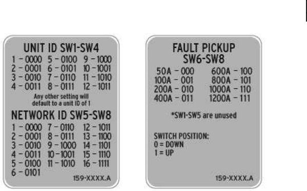
The SEL-FT50 uses two internal eight-position switch banks to configure the
Unit ID, the Network ID, and the Fault Pickup current level.
To begin, open the SEL-FT50 by twisting the bottom counter-clockwise. On
the inside of the device, you will see the two banks of switches. The switch
positions are labeled 1 through 8 on each of the two switch banks. The switch
selections are outlined on a label on the interior of the device, as shown in
Figure 15.
Table 7 Detailed Command Set 3—SEL-FR12 MIRRORED BITS Data Message Contents
Required SEL-651R Transmit MIRRORED BITS (SELOGIC Equations) for Detailed Command Set (2)
TMB1 TMB2 TMB3 TMB4 TMB5 TMB6 TMB7 TMB8
0 0 1 1 0 0 Clear link
state in
SEL-FR12
Target reset
on SEL-FR12
HMI
SEL-651R Received MIRRORED BITS (Relay Word bits)
RMB1 RMB2 RMB3 RMB4 RMB5 RMB6 RMB7 RMB8
Response During Normal Conditions (No Fault on Trio 3 or Trio 4)
Trio 3
FAULT = 0
Trio 4
FAULT = 0
LINK 7 LINK 8 LINK 9 LINK 10 LINK 11 LINK 12
Response During FAULT Indication (One or Both Trio 3 FAULT, Trio 4 FAULT Asserted)
Trio 3 FAULT Trio 4 FAULT FAULT 7 FAULT 8 FAULT 9 FAULT 10 FAULT 11 FAULT 12
19
Date Code 20170317 Instruction Manual SEL-FT50/SEL-FR12 Fault Transmitter and Receiver System
System Installation
Figure 15 Switch Selections Labels
Setting the Unit ID
The SEL-FR12 Fault Receiver receives wireless signals from as many as 12
SEL-FT50 Fault Transmitters on the same network, defined by the
Network ID selection in the SEL-FT50/SEL-FR12 system.
To allow the SEL-FR12 to distinguish which fault transmitter has sent a
message, each SEL-FT50 transmits a Unit ID field as part of the message (the
Unit ID is a number from 1 to 12).
The following lists the requirements when planning the Unit IDs to use in a
system:
➤Unit IDs cannot be duplicated on the network.
➤Not all Unit IDs need to be present.
➤Unit IDs should be grouped in three-phase locations as trios
(see Table 3).
➤Single-phase and two-phase applications are possible in
specific situations.
➤Unit IDs should be marked on the system record for later
installation and commissioning work.
➤Each SEL-FT50 Unit ID is configurable and is selected by the
Unit ID control switches inside the housing.
Setting the Network ID
Configure your SEL-FT50 Fault Transmitters to communicate on the same
network as your SEL-FR12 by giving both devices the same Network ID.
Devices with different Network IDs cannot communicate.
Setting Fault Pickup
The topic of power system coordination is outside the scope of this guide. An
overcurrent element must supervise SEL-FT50 data when used in trip
decisions or other operations affecting protection. Choose an SEL-FT50 Fault
Pickup to be at or below the upstream protective device (e.g., recloser control)
supervising the overcurrent pickup setting (expressed in primary amperes).
Because the SEL-FT50 measurement accuracy is not as accurate as a relay,
take care when choosing your fault pickup settings. The measurement
accuracy for each trip threshold is spelled out in the specifications section.

20
SEL-FT50/SEL-FR12 Fault Transmitter and Receiver System Instruction Manual Date Code 20170317
System Installation
Follow the guidelines in the following table to ensure the right pickup levels
while avoiding false pickups.
This selection method guarantees that the SEL-FT50 picks up for any fault
that the protective device element can see. This setting method will perform
well in locations where fault current is much higher than load current.
The protection planner must consider the load current range on the
distribution system at each node, combined with the SEL-FT50 accuracy
rating at currents below the fault pickup. High load current levels may result in
false assertion of the SEL-FT50 fault detector. In most cases, this is acceptable
because the supervising overcurrent element will not assert. However, the
more frequent a load condition is mistaken for a fault, and the longer each
instance persists, the higher the chance of the SEL-FT50 missing an actual
fault. To avoid this situation, consider selecting the SEL-FT50 Fault Pickup
setting to be one step higher.
Field Installation
Wireless Considerations
Radio Path. Spread-spectrum radios operating in the 900-MHz band are
limited by line-of-sight. Obstructions in the line-of-sight will impact the
performance of the radio, because the strongest radio signal is communicated
directly along the radio line-of-sight. The line-of-sight between two antennas
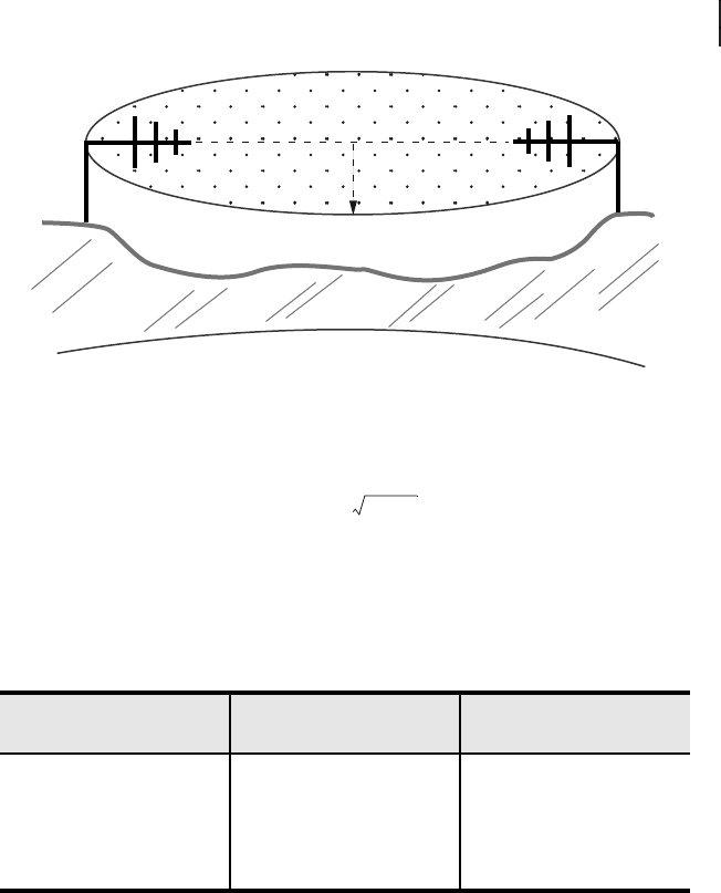
is shaped like an ellipse (called the Fresnel zone). The point exactly halfway
between the two antennas is the widest part of the ellipse, as shown in
Figure 16. At 900 MHz and 304.8 m (1000 ft) apart, the Fresnel zone is 4.9 m
(16 ft) in diameter. At 32 km (20 mi) apart, it is 51.8 m (170 ft) in diameter.
Anything within the Fresnel zone will obstruct and reduce signal strength and
availability (the ground, buildings, vegetation, etc.). Table 9 depicts the
maximum Fresnel zone diameter and path loss for some typical path
distances.
Table 8 Fault Pickup Accuracy Considerations
Fault Pickup Level Host Relay Pickup
Setting Load Behind FT50
50A > 75A < 25A
100A > 130A < 70A
200A > 260A < 140A
400A > 480A < 320A
600A > 720A < 480A
800A > 960A < 640A
1000A > 1200A < 800A
1200A > 1440A < 960A
NOTE: The SEL-FT50 current
measurement circuitry is not as
precise as a protective relay
overcurrent element. Refer to
Specifications on page 25
for fault
pickup accuracy, response
characteristics, and device ratings.
21
Date Code 20170317 Instruction Manual SEL-FT50/SEL-FR12 Fault Transmitter and Receiver System
System Installation
Figure 16 Fresnel Zone
The formula used to calculate the widest distance of the Fresnel zone is as
follows:
where:
b = radius of the Fresnel zone in meters
d = distance between transmitter and receiver in kilometers
f = frequency transmitted in GHz
Obstructions in the Fresnel zone may also cause multipath interference
because of reflective or refractive signals that may arrive at the receiver out of
phase with the desired signal. The Fresnel zone should be at least 60 percent
clear of obstructions for reliable radio communications. Large objects outside
the Fresnel zone can also cause reflections that can affect reliable radio
operation.
Fade Margin. The fade margin determines the allowable signal loss
between the transmitter and receiver. The fade margin is a function of system
gains (transmitter power, receiver sensitivity, and antenna gain) and system
losses (free-space loss, losses because of Earth’s curvature, and coaxial cable
loss). Variations in temperature and humidity of the atmosphere along with
elevation cause the signals to bend more or bend less, resulting in fading at the
receiver. The longer the path, the more likely deep fades will occur, requiring
a greater fade margin. The formula to calculate free-space loss is shown
below.
Free-Space Loss = 92.4 + 20log(f) + 20log(d) dB
where:
f = frequency in GHz
d = distance in km
Regional conditions also impact the probability of signal fade. Generally,
mountainous terrain is more favorable, while tropical areas and those near
large bodies of water are less favorable. Perform a site survey before installing
the SEL-FT50 Fault Transmitters to obtain the fade margin. A fade margin of
10 dB yields adequate performance for noncritical communications links
Table 9 900-MHz Fresnel Zone Radius
Distance Between
Antennas (d) Fresnel Zone Radius (b) Free-Space Loss (dB)
304.8 m (1000 ft) 4.9 m (16 ft) 81
1.6 km (1 mi) 11.6 m (38 ft) 96
8 km (5 mi) 25.9 m (85 ft) 110
16 km (10 mi) 36.6 m (120 ft) 116
d
b
b 17.32 d 4f e=
22
SEL-FT50/SEL-FR12 Fault Transmitter and Receiver System Instruction Manual Date Code 20170317
System Installation
while a fade margin of 15 dB yields good radio performance for critical
communications links.
Site Survey. A line-of-sight path provides the most reliable transmission
in all cases. As the distance increases, the need for a clear path becomes more
critical in creating a reliable, available radio link. If you have a clear line-of-
sight to the other location without obstructions to the Fresnel zone (see Radio
Path on page 20) then a path study is generally not needed. Longer distances
may require a path study, a visual path inspection, and a spectrum analysis of
the area to give a good indication of how high the antenna needs to be and how
good the radio link will be.
Radio Interference. The SEL-FT50 shares frequency spectrum with other
services and FCC Part 15 (unlicensed) devices in ITU Region 2 (North,
Central, and South America). Error-free communication may not be
achievable in a given location and some level of interference should be
expected. For a given fault, the SEL-FT50 sends four consecutive messages.
This mitigates the effect of radio interference by increasing the odds that a
fault indication will be communicated successfully during situations with poor
channel conditions.
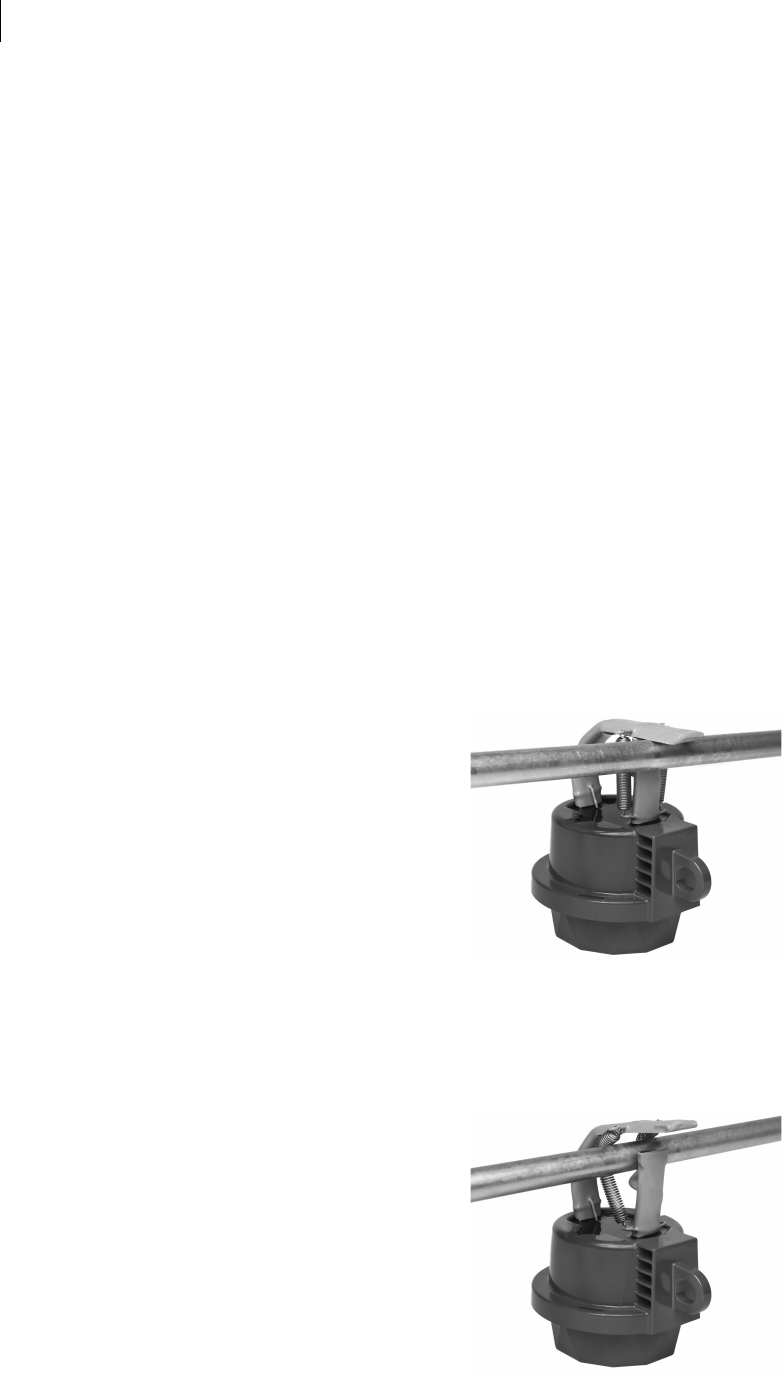
Physical Installation
Install the SEL-FT50 on a distribution line by using an industry-standard hot
stick.
Step 1. Use a hot stick to grasp the hook eye on the side of the
SEL-FT50, and place the device on the line so that the opening
hangs over the line.
Figure 17 Positioning the SEL-FT50
Step 2. Apply slight downward and sideways pressure until the device
is closed around the line.
The spring mechanism should be pushed in, so that it wraps
around the line.
Figure 18 SEL-FT50 Installation Position
23
Date Code 20170317 Instruction Manual SEL-FT50/SEL-FR12 Fault Transmitter and Receiver System
Dimensions
Step 3. Apply slight upward pressure until the device is secured around
the line as shown in Figure 19.
Figure 19 SEL-FT50 Secure on the Line
Step 4. Use the hot stick to adjust the transmitter orientation so that it is
directly vertical. This is important to ensure the best
propagation characteristics for the internal antenna.
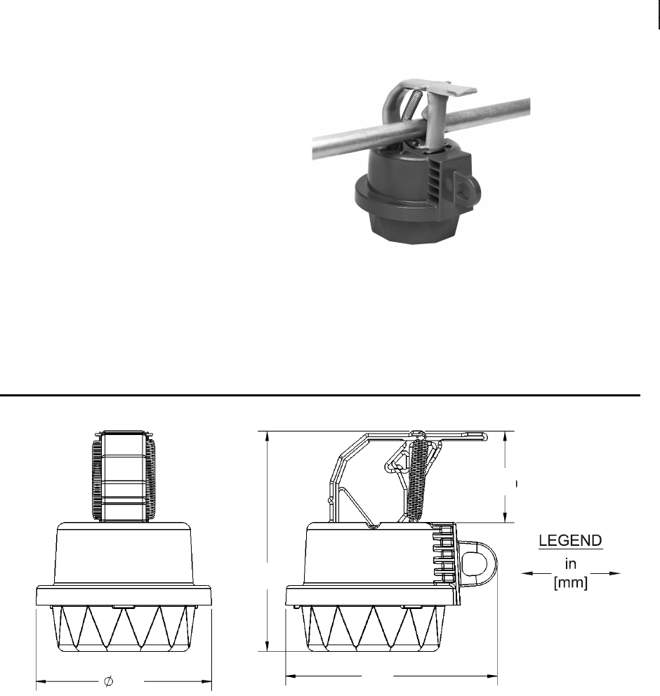
Dimensions
Figure 20 SEL-FT50 Dimensions
5.71
(145.03)
5.83
(148.08)
2.47
(62.74)
4.75
(120.55)
24
SEL-FT50/SEL-FR12 Fault Transmitter and Receiver System Instruction Manual Date Code 20170317
Dimensions
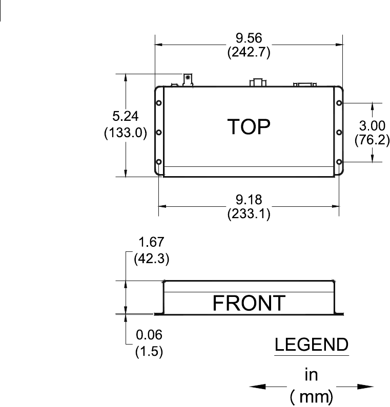
Figure 21 SEL-FR12 Dimensions

25
Date Code 20170317 Instruction Manual SEL-FT50/SEL-FR12 Fault Transmitter and Receiver System
Specifications
Specifications
Compliance
Designed and manufactured under an ISO 9001 certified quality
management system.
General
Operating Temperature
–40° to +85°C (–40° to +185°F)
Storage Temperature
–40° to +85°C (–40° to +185°F)
Operating Environment
Pollution Degree: 2
Relative Humidity: 5–95%, noncondensing
Maximum Altitude: 2000 m
Ingress Protection (SEL-FT50)
IP67
Clamp Range (SEL-FT50)
7.6 mm to 27.9 mm (0.3 in to 1.1 in)
Dimensions
SEL-FT50: 145 mm diameter x 148 mm height
(5.71 in. diameter x 5.83 in. height)
SEL-FR12: 44 mm x 243 mm x 117 mm
(1.73 in x 9.57 in x 4.61 in)
Weight
SEL-FT50: 0.6 kg (1.3 lb)
System
Power System Frequency Range
45–65 Hz
Current Pickup Level
Note: Units are individually configurable.
50, 100, 200, 400, 600, 800, 1000, 1200 A
Fault Detection Accuracy
50 A Threshold: 50%
100 A, 200 A Threshold: 30%
400 A Threshold and
Above: 20%
Maximum Voltage
38 kV (L-L)
Power
SEL-FT50 Minimum Radio Link Active Current
15 A
SEL-FR12 Power Requirements
Voltage: 9–30 Vdc
Power Consumption: < 2 W
Radio System
Frequency Band
902–928 MHz ISM band
SEL-FT50
TX Power: 700 mW (28 dBm)
SEL-FR12
Number of Channels: 12
Antenna Connector: BNC, 50 :
RX Sensitivity: –100 dBm at 1% error rate
Serial Protocol: MIRRORED BITS communications
Serial Port: 9600, 19200, 38400, 115200 bps
Modulation
FSK
Typical Range
4 miles with 20 dB of interference/fade margin

26
SEL-FT50/SEL-FR12 Fault Transmitter and Receiver System Instruction Manual Date Code 20170317
Appendix A: Manual Versions
Appendix A: Manual Versions
Instruction Manual The date code at the bottom of each page of this manual reflects the creation
or revision date.
Table 10 lists the instruction manual versions and revision descriptions. The
most recent instruction manual version is listed first.
Table 10 Instruction Manual Revision History
Date Code Summary of Revisions
20170317 ➤Initial version.
27
Date Code 20170317 Instruction Manual SEL-FT50/SEL-FR12 Fault Transmitter and Receiver System
Appendix B: Two Branch Application
Appendix B: Two Branch Application
Two Branch
Application
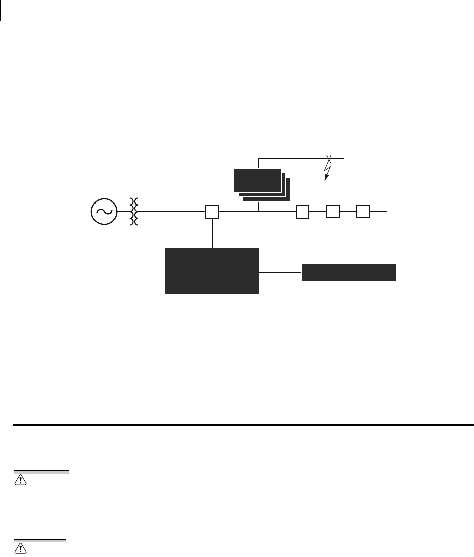
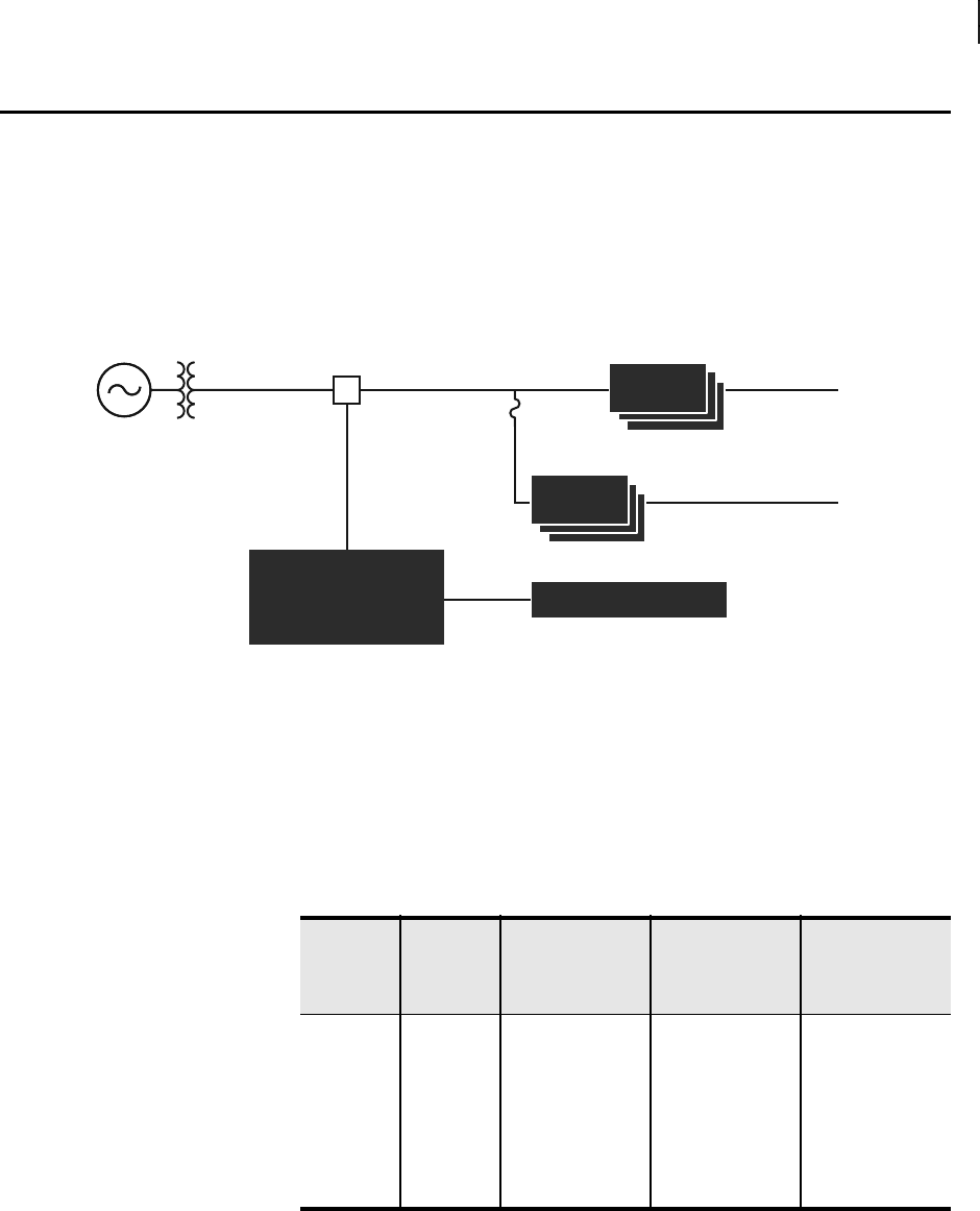
This application has two three-phase branches, A and B, as shown in
Figure 22. Branch B has a fuse and uses a fuse-blowing scheme, while
Branch A does not. When a fault occurs on Branch A, the recloser operates to
clear the fault. In traditional protection schemes, those without the
SEL-FT50/SEL-FR12 system, the time-inverse overcurrent curves of the
SEL-651R recloser control are set above the fuse-clearing curve, resulting in
longer tripping times for faults on Branch A. Use the SEL-FT50/SEL-FR12
system to improve this protection scheme.
Figure 22 SEL-FT50/SEL-FR12 System Protection Scheme
Insert a set of three SEL-FT50 Fault Transmitters on each branch, one per
phase. The SEL-FR12 connects to the SEL-651R with an SEL-C272 serial
cable. In this example, the load current of Branch A is 200 A, and the load
current of Branch B is 100 A. The 51 element pickup of the SEL-651R is set
above 200 percent of the load current. In this example, the fuse size is 140 T,
the SEL-651R 51 element pickup is 550 A, and the settings from Table 11
apply.
This settings example uses Network ID = 3, and the fault current pickup
threshold is set above the load current and below the pickup.
The Network ID of the SEL-FR12 matches the Network ID of the SEL-FT50
Fault Transmitters. Table 12 assumes that the distances of the SEL-FT50 Fault
Transmitters are farther than 300 m (1000 ft). See Table 13 for the settings of
the SEL-651R and Table 14 for the SEL-651R transmit MIRRORED BITS
settings.
R
SEL-FR12
SEL-651R-2
SEL-FT50
SEL-FT50
123
456
A
B
Table 11 Settings for the SEL-FT50 Fault Transmitters
SEL-FT50 Branch
Unit ID
Control (DIP)
Switch Positions
Network ID
Control (DIP)
Switch Positions
Pickup
Threshold
Control (DIP)
Switch Positions
1 A 1—(0000) 3—(0010) 400 A—(011)
2 A 2—(0001) 3—(0010) 400 A—(011)
3 A 3—(0010) 3—(0010) 400 A—(011)
4 B 4—(0011) 3—(0010) 200 A—(010)
5 B 5—(0100) 3—(0010) 200 A—(010)
6 B 6—(0101) 3—(0010) 200 A—(010)

28
SEL-FT50/SEL-FR12 Fault Transmitter and Receiver System Instruction Manual Date Code 20170317
Appendix B: Two Branch Application
With these settings, Branch B operates using a fuse-blowing scheme where the
fuse clears faults on the branch, while Branch A operates separately, tripping
much faster because the protection does not wait for a fuse-coordination delay.
Table 12 Settings for the SEL-FR12
Network ID BAUD RX_ADD TX_ADD Trio 1 Distance Trio 2 Distance Trio 3 Distance Trio 4 Distance
3—(0010) 38400 1 2 > 300 m (1000 ft) > 300 m (1000 ft) > 300 m (1000 ft) > 300 m (1000 ft)
Table 13 SEL-651R Settings
PROTO SPEED TXID RXID
MB8A or MB8B 38400 1 2
Table 14 SEL-651R Transmit MIRRORED BITS Settings
TMB1A TMB2A TMB3A TMB4A TMB5A TMB6A TMB7A TMB8A Comments
0 0 0 0 0 0 0 TRGTR The TARGET RESET pushbutton of
the SEL-651R resets the latched
FAULT LEDs of the SEL-FR12.

SEL-FT50/SEL-FR12 Fault Transmitter and Receiver System Instruction Manual Date Code 20170317
29 Appendix B: Two Branch Application
© 2017 by Schweitzer Engineering Laboratories, Inc. All rights reserved.
All brand or product names appearing in this document are the trademark or regis-
tered trademark of their respective holders. No SEL trademarks may be used with-
out written permission. SEL products appearing in this document may be covered by
U.S. and Foreign patents.
Schweitzer Engineering Laboratories, Inc. reserves all rights and benefits afforded
under federal and international copyright and patent laws in its products, including
without limitation software, firmware, and documentation.
The information in this document is provided for informational use only and is sub-
ject to change without notice. Schweitzer Engineering Laboratories, Inc. has
approved only the English language document.
This product is covered by the standard SEL 10-year warranty. For warranty details,
visit selinc.com or contact your customer service representative. *PMFR12-01*
2350 NE Hopkins Court • Pullman, WA 99163-5603 U.S.A.
Tel: +1.509.332.1890 • Fax: +1.509.332.7990
selinc.com • info@selinc.com