Schweitzer Engineering Laboratories SEL-3031 SEL-3031 User Manual 3031 IM
Schweitzer Engineering Laboratories, Inc. SEL-3031 3031 IM
UserManual.wiki
>
Schweitzer Engineering Laboratories
>
SEL-3031 User Manual
>
User Manual
Contents
1.
User Manual
2.
user manual
User Manual
Navigation menu
Upload a User Manual
Namespaces
Wiki Guide
HTML
PDF
Info
Views
User Manual
Discussion / Help
Navigation

![SEL-3031 Instruction Manual Date Code 20091009Settings and CommandsSettings4.6Step 3. Type the filename and click Open.a. Highlight the device or setting in the A database.b. Select Copy or Move, and click the > button to create a new device or setting in the B database.Step 4. Reverse this process to take devices from the B database to the A database. Copy creates an identical device that appears in both databases. Move removes the device from one database and places the device in another database.Create a New Database/Copy an Existing DatabaseTo create a new database, perform the following:Step 1. Open File > Database Manager and click Create New Database. ACSELERATOR QuickSet will prompt you for a file name.Step 2. Type the new database name (and location if it differs from the previous database location), and click Save. ACSELERATOR QuickSet displays the message Settings [path and file name] was successfully created.Step 3. Click OK.To copy an existing database of devices to a new database, perform the following:Step 1. Open File > Database Manager and click Copy/Move Settings Between Databases in the Database Manager dialog box. ACSELERATOR QuickSet will open the last active database and assign it as Database A.Step 2. Click Open B. ACSELERATOR QuickSet will prompt you for a file location. Type the new database name, click Open, and click Yes. The program will then create an empty database. Load devices into the new database as shown in Copy/Move Settings Between Databases.SettingsACSELERATOR QuickSet allows you to create settings for one or more SEL-3031 devices. Store existing device settings downloaded from the SEL-3031 by creating a library of settings, then modify and upload these settings from the library to an SEL-3031. ACSELERATOR QuickSet makes setting the device easy and efficient and provides rules-based settings checks, commissioning, and help.Settings EditorThe Settings Editor shows device settings in easy-to-understand categories. and makes setting the device simple and efficient. Settings are grouped logically, and settings that are not used in the selected group are dimmed (grayed) in the ACSELERATOR QuickSet](https://usermanual.wiki/Schweitzer-Engineering-Laboratories/SEL-3031.User-Manual/User-Guide-1198661-Page-54.png)
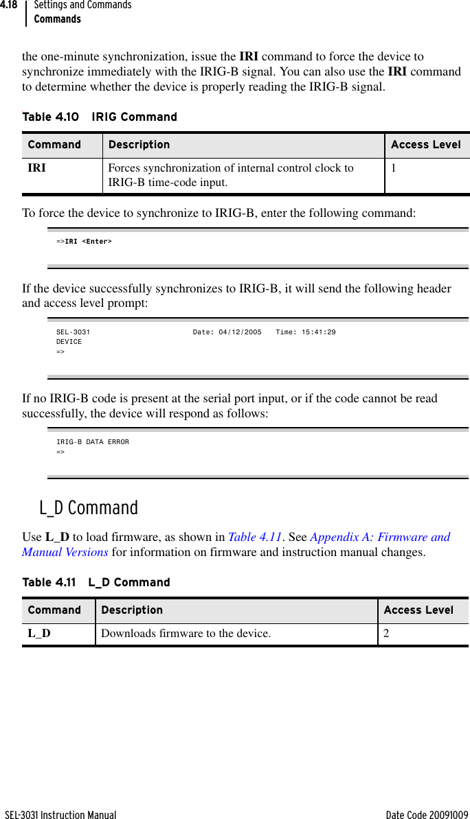
![SEL-3031 Instruction Manual Date Code 20091009Settings and CommandsCommands4.20If you forget your password, you can reissue a new password by following these steps:Step 1. In accordance with the appropriate safety regulations, turn off the device, and see Front-Panel Jumpers on page 2.9 for instructions on accessing the jumpers.Step 2. Go to Table 2.5 to locate Jumper 2 and short the jumper as shown.Step 3. Go to the appropriate access level and issue PAS x (x = 1 or 2) to enter a new password.Step 4. In accordance with the appropriate safety regulations, turn off the device and remove Jumper 2 to activate the password function.Step 5. Replace the front-panel cover and turn on the device.QUIT CommandUse QUIT to revert to Access Level 0 from either Access Level 1 or Access Level 2, as shown in Table 4.15.Access Level 0 is the lowest access level; your SEL-3031 does not require a password check to descend to this level (or to remain at this level).RADIO CommandThe RAD command is for viewing statistics and data on the radio link, as shown in Table 4.16. The RAD command provides two important types of information.➤RSSI = Receive Signal Strength Indicator. The RSSI shows the current strength of the receive signal from the radio. This command helps you to refine antenna positioning. The RSSI is reported in dBm and updates every time the RAD command is issued. The RSSI is calculated from the latest 50 frequency hops averaged over time. RSSI is very useful for optimizing performance on directional antennas and monitoring signal strength.Table 4.14 Valid Password CharactersAlpha A B C D E F G H I J K L M N O P Q R S T U V W X Y Za b c d e f g h i j k l m n o p q r s t u v w x y zNumeric 0 1 2 3 4 5 6 7 8 9Special ! “ # $ % & ‘ ( ) * + , - . / : ; , = . ? @ [ \ ] ^ _ ‘ { | } ~Ta b le 4.1 5 Q U IT Co m ma n dCommand Description Access LevelQUI Sends you to Access Level 0. 0](https://usermanual.wiki/Schweitzer-Engineering-Laboratories/SEL-3031.User-Manual/User-Guide-1198661-Page-68.png)
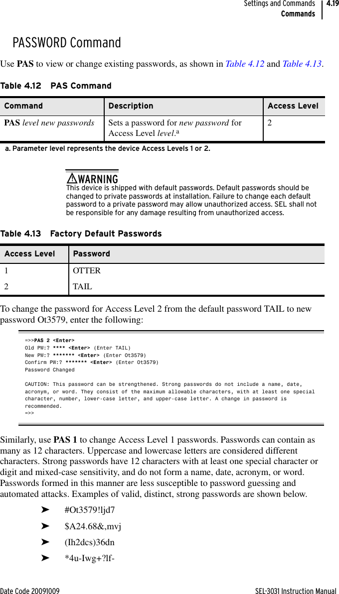
![Date Code 20091009 SEL-3031 Instruction ManualSettings and CommandsCommands4.21➤AVAILABILITY. The radio automatically calculates the availability of the overall radio link and the availability of each hopping frequency. The availability is calculated by measuring the number of good radio frames received per the number of radio frames expected. The Overall is the tallied availability of each of the frequency zones used in the current hopping table. This number is valuable for measuring overall radio availability. The SEL-3031 also calculates the availability of each zone used in the current hopping table. The radio zones displayed in the RAD command are based on the SKIP setting. See Table 4.5 for more information on Skip Zones. See Section 5: Performance Monitoring, Testing, and Troubleshooting for more information on using the availability to set the SKIP setting for improved radio performance.1 2 3 4 5 6 7 812345678901234567890123456789012345678901234567890123456789012345678901234567890[Common Header]RSSI -69 dBmAVAILABILITY: From 10/02/2009 17:33:21Overall100.00 %Zone 1 Zone 2 Zone 3 Zone 4 Zone 5100.00 % 100.00 % 100.00 % 100.00 % 100.00 %Zone 6 Zone 7 Zone 8 Zone 9 Zone 10100.00 % 100.00 % 100.00 % 100.00 % 100.00 %Figure 4.10 RAD Command ResponseTa b le 4.1 6 RA D Comm andCommand Description Access LevelRAD View radio statistics 1RAD C Clear radio statistics 2](https://usermanual.wiki/Schweitzer-Engineering-Laboratories/SEL-3031.User-Manual/User-Guide-1198661-Page-69.png)