Schweitzer Engineering Laboratories SEL-3031 SEL-3031 User Manual 3031 IM 20181001
Schweitzer Engineering Laboratories, Inc. SEL-3031 3031 IM 20181001
UserManual.wiki
>
Schweitzer Engineering Laboratories
>
SEL-3031 User Manual
>
user manual
Contents
1.
User Manual
2.
user manual
user manual
Navigation menu
Upload a User Manual
Namespaces
Wiki Guide
HTML
PDF
Info
Views
User Manual
Discussion / Help
Navigation


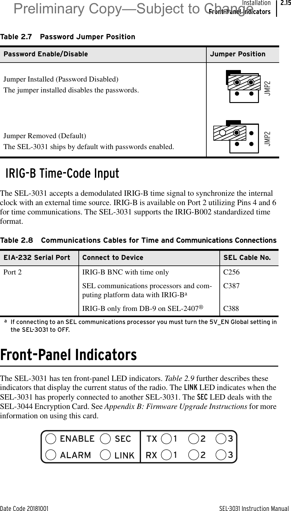
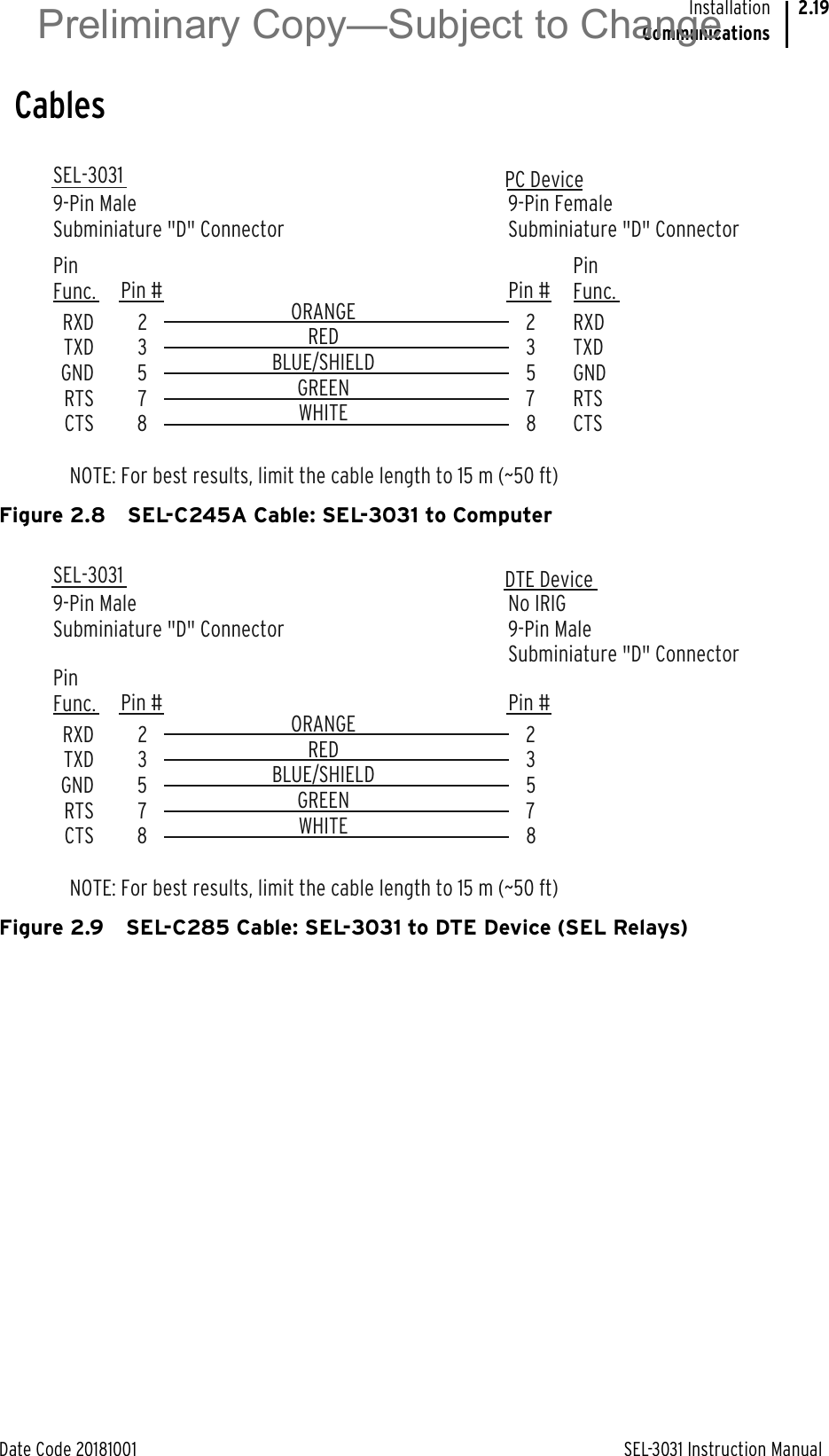

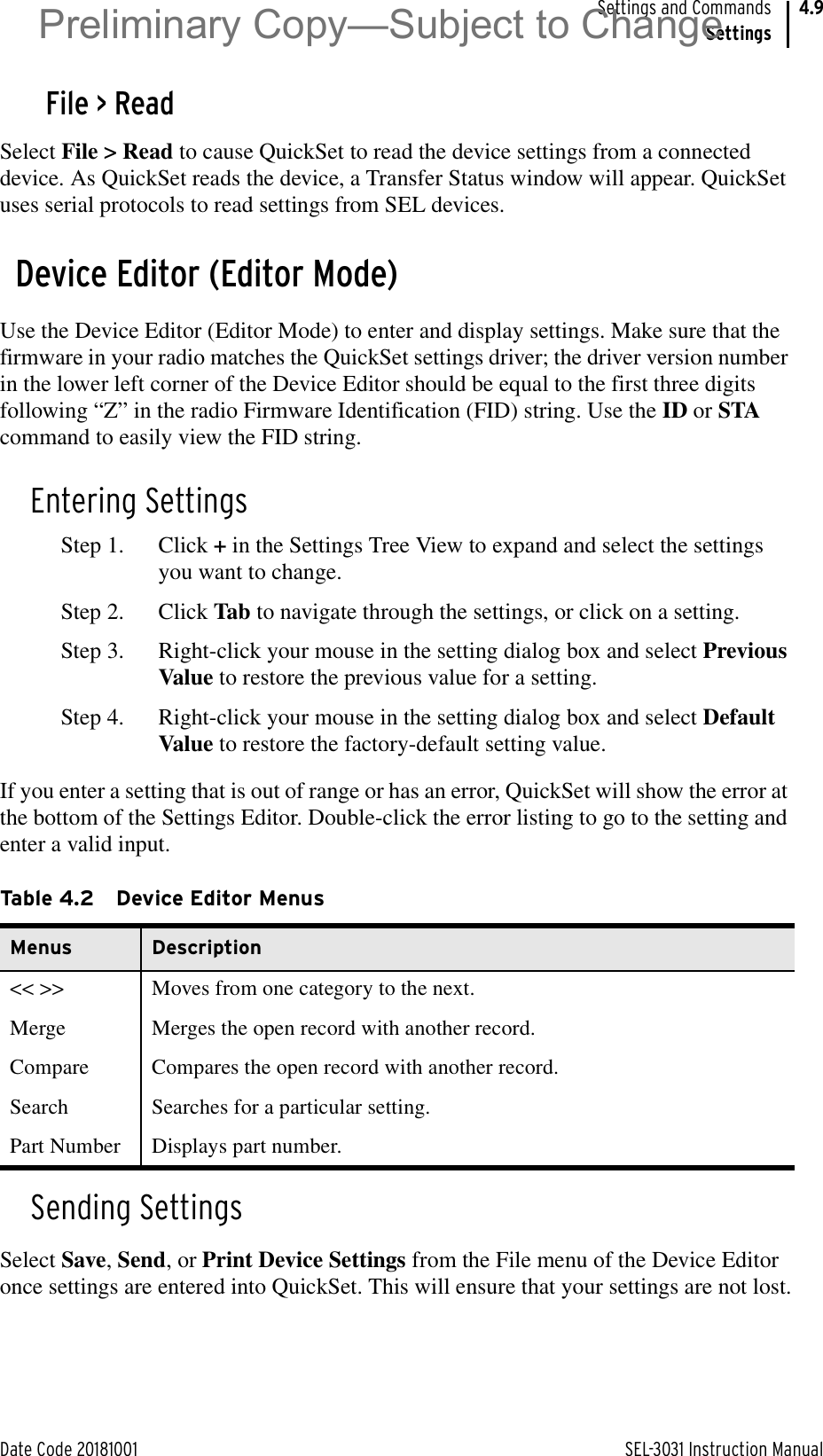
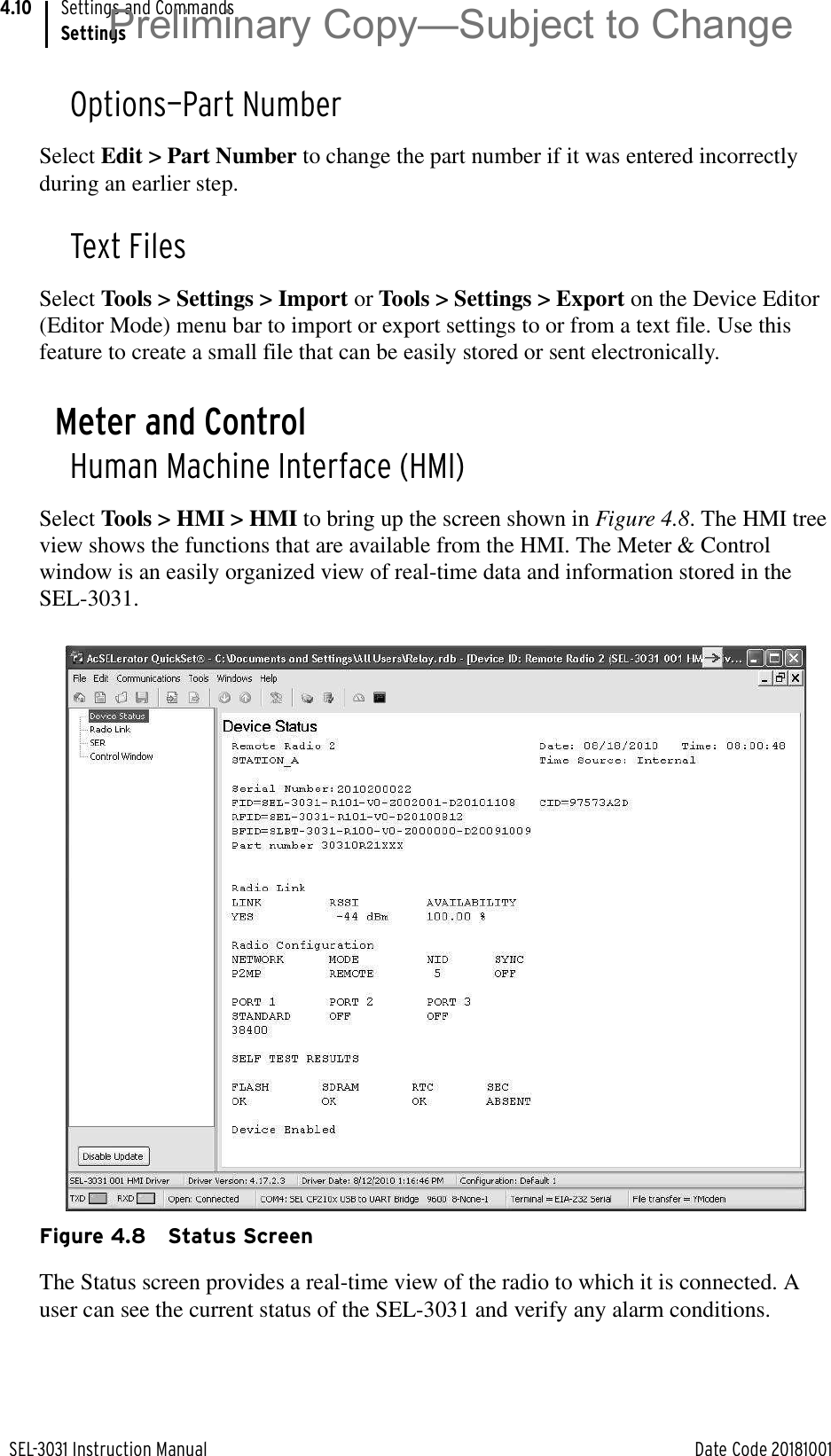
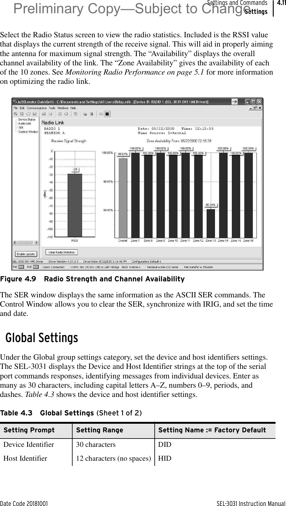
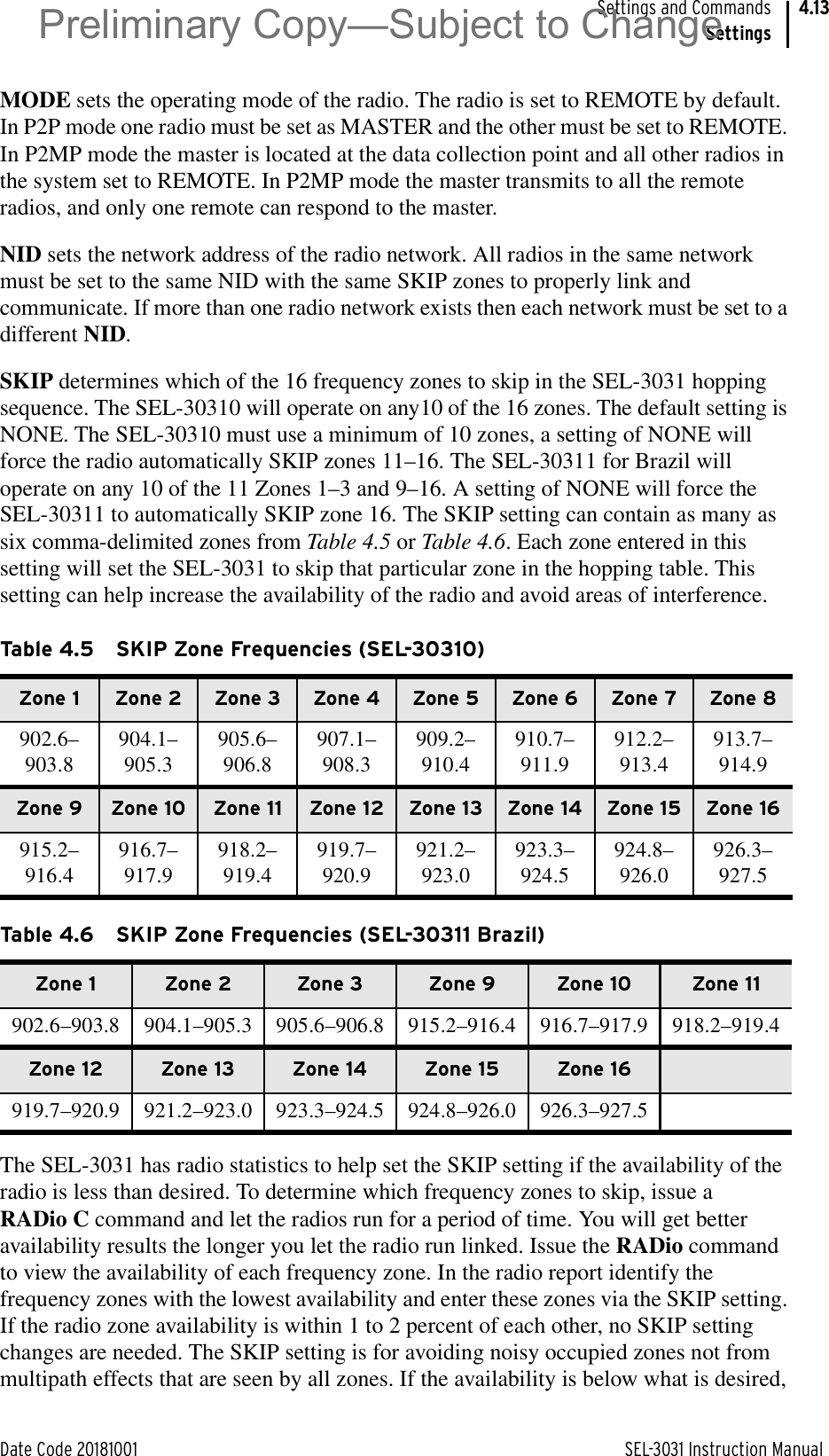
![SEL-3031 Instruction Manual Date Code 20181001Settings and CommandsSettings4.6Step 3. Type the filename and click Open.a. Highlight the device or setting in the A database.b. Select Copy or Move, and click the > button to create a new device or setting in the B database.Step 4. Reverse this process to take devices from the B database to the A database. Copy creates an identical device that appears in both databases. Move removes the device from one database and places the device in another database.Create a New Database/Copy an Existing DatabaseTo create a new database, perform the following:Step 1. Open File > Database Manager and click Create New Database. QuickSet will prompt you for a file name.Step 2. Type the new database name (and location if it differs from the previous database location), and click Save. QuickSet displays the message Settings [path and file name] was successfully created.Step 3. Click OK.To copy an existing database of devices to a new database, perform the following:Step 1. Open File > Database Manager and click Copy/Move Settings Between Databases in the Database Manager dialog box. QuickSet will open the last active database and assign it as Database A.Step 2. Click Open B. QuickSet will prompt you for a file location. Type the new database name, click Open, and click Yes. The program will then create an empty database. Load devices into the new database as shown in Copy/Move Settings Between Databases.SettingsQuickSet allows you to create settings for one or more SEL-3031 devices. Store existing device settings downloaded from the SEL-3031 by creating a library of settings, then modify and upload these settings from the library to an SEL-3031. QuickSet makes setting the device easy and efficient and provides rules-based settings checks, commissioning, and help.Settings EditorThe Settings Editor shows device settings in easy-to-understand categories. and makes setting the device simple and efficient. Settings are grouped logically, and settings that are not used in the selected group are dimmed (grayed) in the QuickSet menus. Preliminary Copy—Subject to Change](https://usermanual.wiki/Schweitzer-Engineering-Laboratories/SEL-3031.user-manual/User-Guide-4032472-Page-70.png)
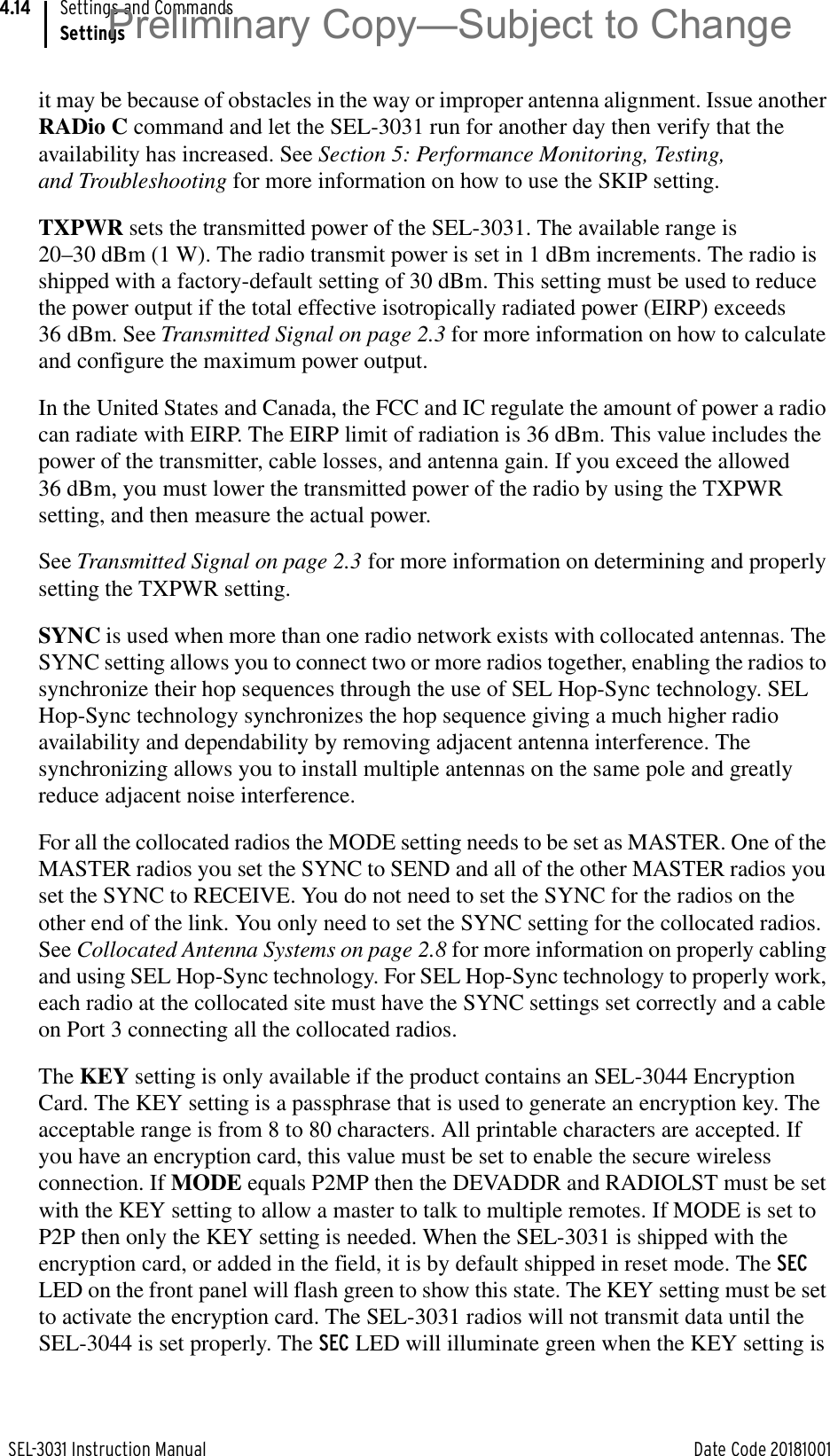

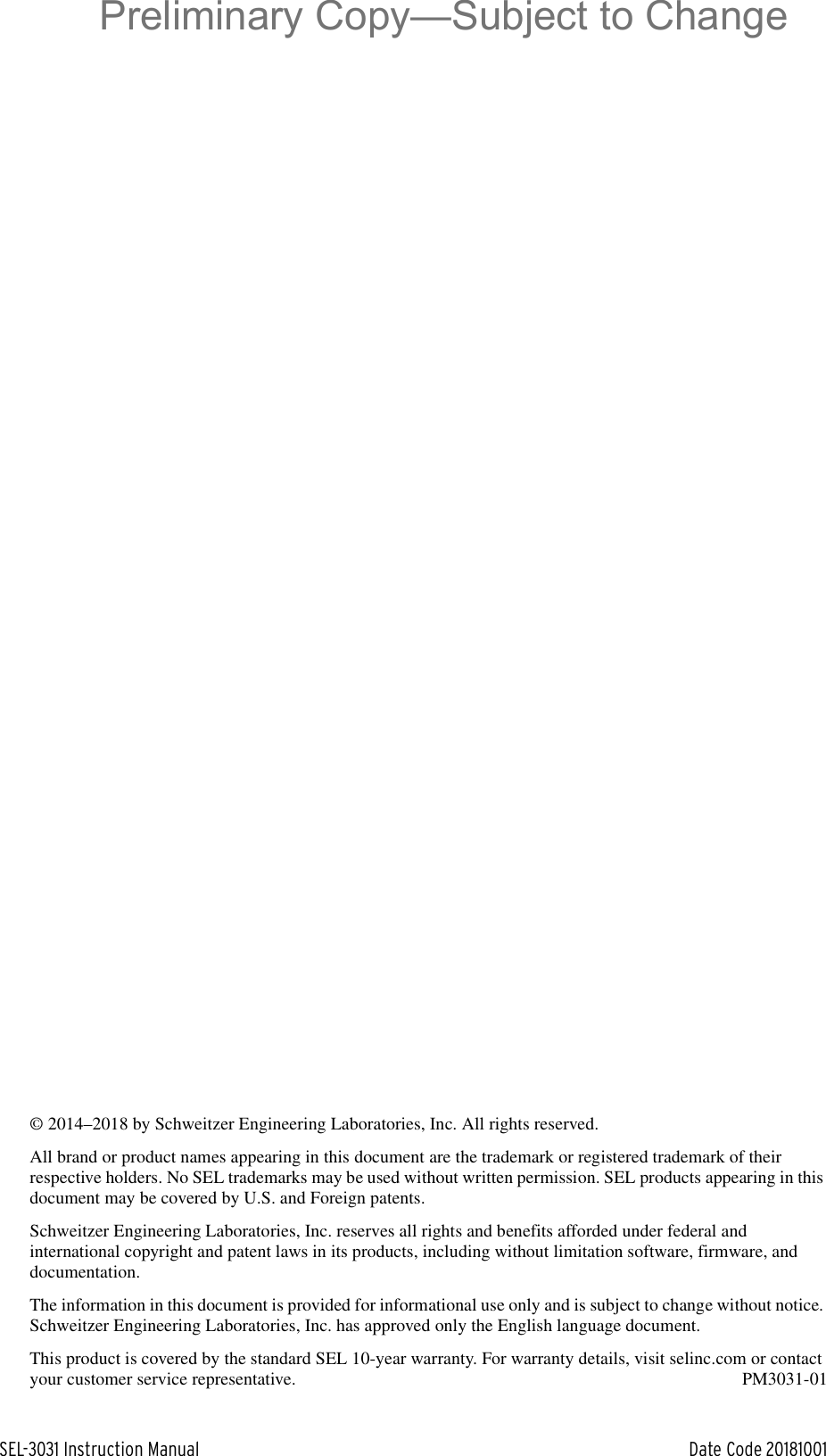
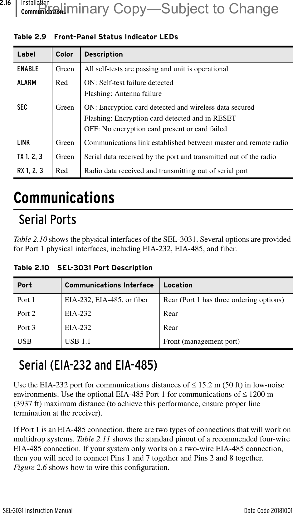
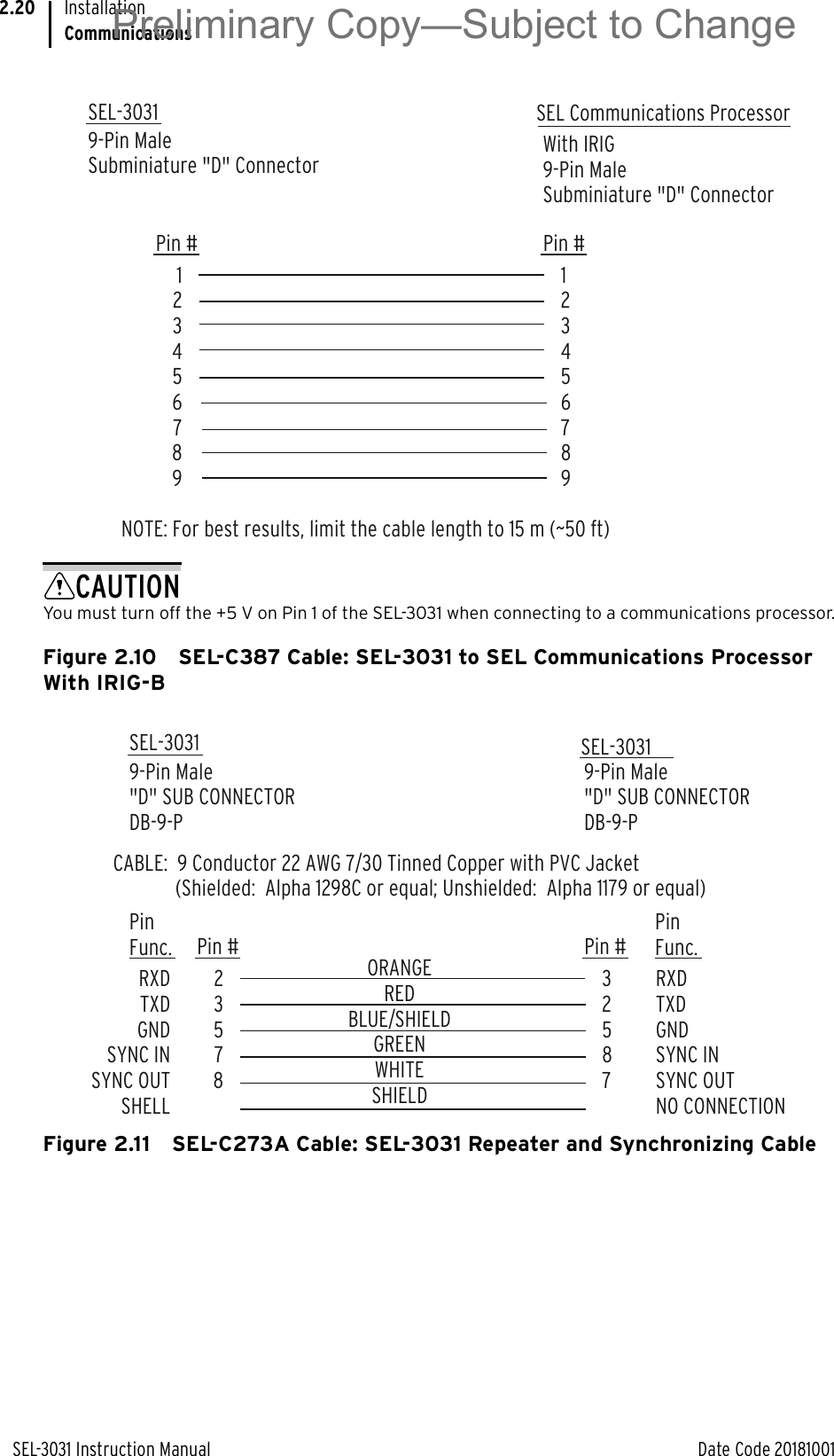
![SEL-3031 Instruction Manual Date Code 20181001Settings and CommandsCommands4.22Password ChangedCAUTION: This password can be strengthened. Strong passwords do not include a name, date, acronym, or word. They consist of the maximum allowable characters, with at least one special character, number, lower-case letter, and upper-case letter. A change in password is recommended.=>>Similarly, use PAS 1 to change Access Level 1 passwords. Passwords can contain as many as 12 characters. Uppercase and lowercase letters are considered different characters. Strong passwords have 12 characters with at least one special character or digit and mixed-case sensitivity, and do not form a name, date, acronym, or word. Passwords formed in this manner are less susceptible to password guessing and automated attacks. Examples of valid, distinct, strong passwords are shown below.➤#Ot3579!ljd7➤$A24.68&,mvj➤(Ih2dcs)36dn➤*4u-Iwg+?lf-If you forget your password, you can reissue a new password by following these steps:Step 1. In accordance with the appropriate safety regulations, turn off the device, and see Front-Panel Jumpers on page 2.14 for instructions on accessing the jumpers.Step 2. Go to Table 2.7 to locate Jumper 2 and short the jumper as shown.Step 3. Go to the appropriate access level and issue PAS x (x = 1 or 2) to enter a new password.Step 4. In accordance with the appropriate safety regulations, turn off the device and remove Jumper 2 to activate the password function.Step 5. Replace the front-panel cover and turn on the device.Table 4.15 Valid Password CharactersAlpha A B C D E F G H I J K L M N O P Q R S T U V W X Y Za b c d e f g h i j k l m n o p q r s t u v w x y zNumeric 0 1 2 3 4 5 6 7 8 9Special ! “ # $ % & ‘ ( ) * + , - . / : ; , = . ? @ [ \ ] ^ _ ‘ { | } ~Preliminary Copy—Subject to Change](https://usermanual.wiki/Schweitzer-Engineering-Laboratories/SEL-3031.user-manual/User-Guide-4032472-Page-86.png)
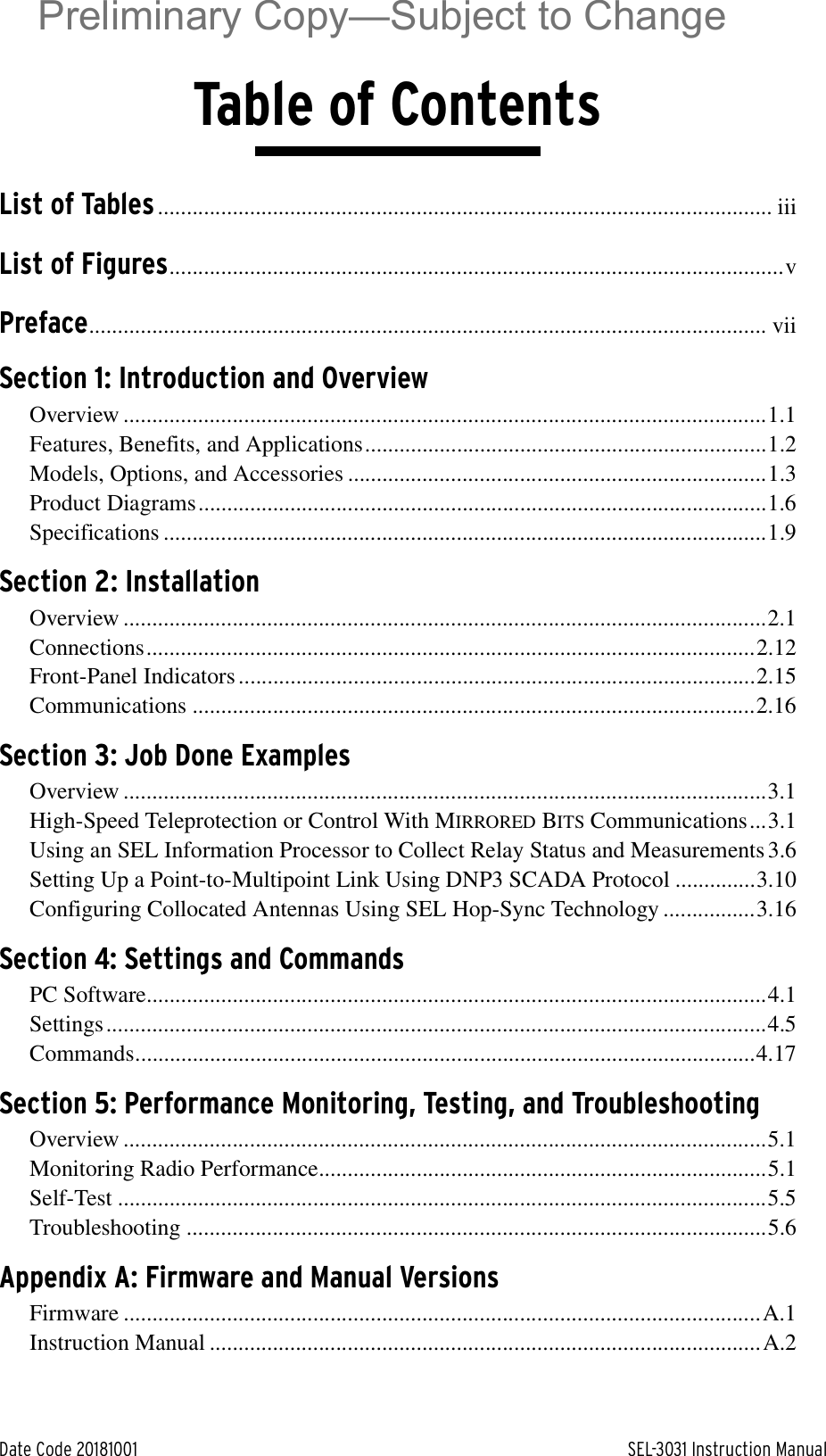
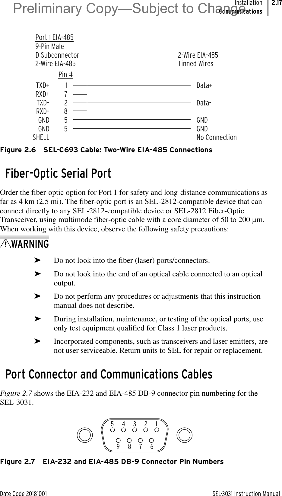
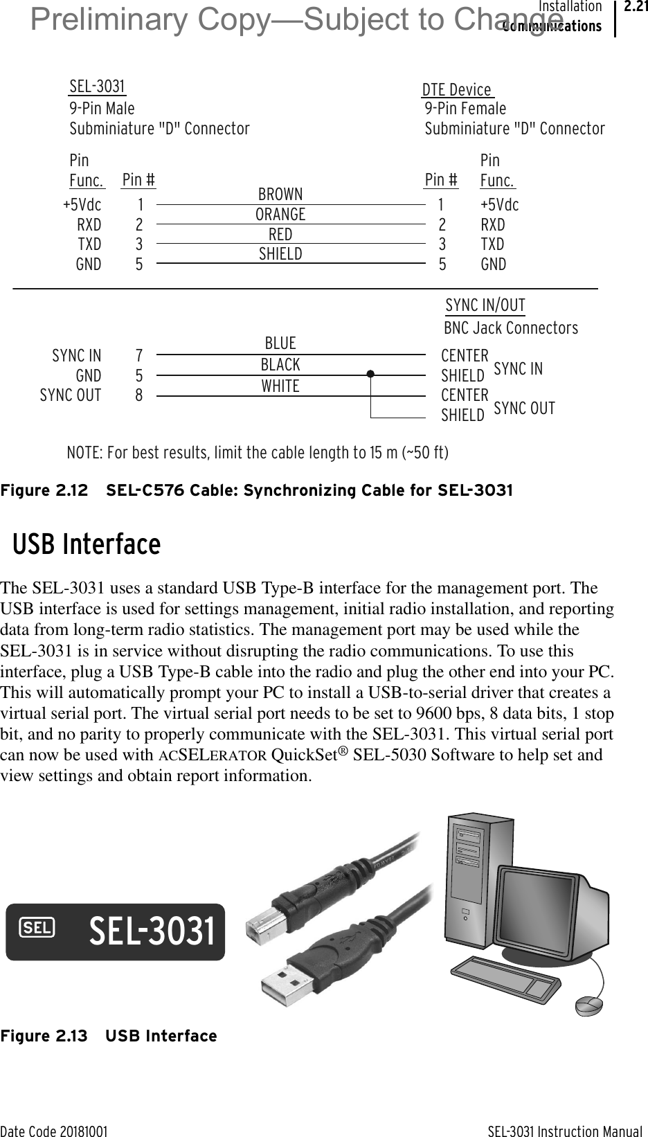
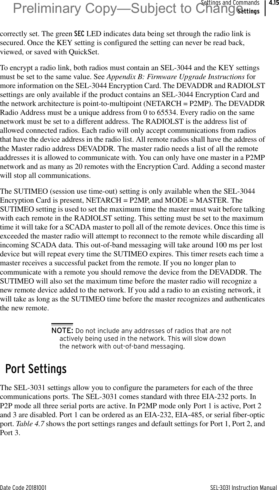
![SEL-3031 Instruction Manual Date Code 20181001Settings and CommandsCommands4.241 2 3 4 5 6 7 812345678901234567890123456789012345678901234567890123456789012345678901234567890[Common Header]RSSI -69 dBmAVAILABILITY: From 10/02/2009 17:33:21Overall100.00 %Zone 1 Zone 2 Zone 3 Zone 4 Zone 5100.00 % 100.00 % 100.00 % 100.00 % 100.00 %Zone 6 Zone 7 Zone 8 Zone 9 Zone 10100.00 % 100.00 % 100.00 % 100.00 % 100.00 %Figure 4.10 RAD Command ResponseSER CommandUse SER to view and manage the Sequential Events Recorder report, as shown in Table 4.18.If the requested SER report rows do not exist, the device will respond with the following:NO SER dataSET CommandThe SET command is for viewing or changing device settings, as shown in Table 4.19. Append TERSE to skip the settings display after the last setting. Use this parameter to speed up the SET command. If you want to review the settings before saving, do not use the TERSE option.Table 4.18 SER CommandCommand Description Access LevelSER Displays a chronological progression of all avail-able SER rows (as many as 1024 rows); Row 1 is the most recent and Row 1024 is the oldest.1SER row 1SER row 1 row 2SER date 1SER date 1 date 2Displays a chronological or reverse chronological subset of the SER rows.1SER C Clears/resets all SER records. 2Preliminary Copy—Subject to Change](https://usermanual.wiki/Schweitzer-Engineering-Laboratories/SEL-3031.user-manual/User-Guide-4032472-Page-88.png)