Schwinn 122 Assembly Manual 101C Schwinn® Upright Exercise Bike
Schwinn 122 Upright Exercise Bike Assembly Manual SCH_122-123_AM_web Troubleshoot Schwinn 122 Upright Exercise Bike Assembly |
FITNESS 123 SCH_122-123_AM_web
2015-05-15
: Schwinn Schwinn-122-Assembly-Manual-718391 schwinn-122-assembly-manual-718391 schwinn pdf
Open the PDF directly: View PDF ![]() .
.
Page Count: 16
- Assembly Instructions
- FITNESS SAFEGUARDS AND WARNINGS
- Other Important Safeguards and Warnings
122/123 Schwinn® Upright Exercise Bike
Parts List
Full Size Hardware Chart
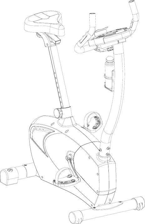
Product Illustration
Assembly Instructions
e-mail from: Keith Weier date: 7/14/2005 page:1/16
FITNESS SAFEGUARDS AND WARNINGS
Before starting any exercise program, consult with your physician or health
professional. He or she can help establish the correct exercise frequency,
intensity (target heart rate zone) and time appropriate for your particular age and
condition.
The following 3 warnings listed below are also located on the computer console
mast of the exercise bike. Failure to follow any of these safeguards may result in
injury or serious health problems.
• Read and understand the Owner’s Manual and operation instructions prior
to use. If you do not have an Owner’s Manual, call 1-800-864-1270 to
obtain one.
• If you feel any unusual pain or tightness in your chest, shortness of breath
or dizziness, feel faint or have any discomfort while you exercise, STOP!
Consult your physician.
• Keep children and pets away.
Other Important Safeguards and Warnings
• Do not exceed maximum user weight of 136 kg (300 lb.)
• It is the responsibility of the owner to ensure that all users of this
equipment are adequately informed of all precautions.
• Use this equipment only on a solid level surface. Cover the floor or carpet
beneath this equipment for protection.
• Read the Warning Label located on the computer console mast.
• Do not place fingers or any other objects into moving parts of the exercise
equipment.
• This equipment is designed for use by persons aged 13 years and older.
Teenagers should be supervised.
• Always wear athletic shoes for foot protection. Avoid wearing loose
clothing that may become entangled in the drive mechanism.
• Warn bystanders to keep a safe distance, especially from the moving
pedals. Do not allow anyone to touch the bike while it is in operation.
• This equipment is for home use only. Do not use in a commercial,
institutional, or rental setting.
• Care should be taken when mounting or dismounting the exercise bicycle.
• Do not operate in damp or wet conditions.
• Follow proper set-up and guidance as outlined in the Owner’s Manual and
Assembly Instructions. Only use the bike as outlined in usage instructions
of the Owner’s Manual.
• Prior to each use inspect the bike for loose, broken, or worn parts. Do not
use if found in this condition. The safety of the equipment can only be
e-mail from: Keith Weier date: 7/14/2005 page:2/16
ensured if it is regularly examined and maintained. (See Maintenance
section of the Owner’s Manual)
• Refer to the Maintenance section in the Owner’s Manual and disconnect
power supply before servicing the bike.
• Replace Warning Label if damaged, illegible, or removed.
• We recommend that a minimum distance of 1 meter (39 inches)
surrounding the bike is kept clear of all obstructions, including children,
bystanders, and pets. This is to ensure adequate clearance for easy
access to the bike and to avoid any possible contact with the moving
pedals
122/123 Schwinn Upright Bike Parts List,
Hardware Chart, and Assembly Instructions
Assembly of the 122/123 Upright Bike is divided into 7 easy stages; each
comprised of only a few setup steps. Before proceeding with the assembly,
please read over the easy to follow instructions to familiarize yourself with the
process.
• A flat area of 4’ x 6’ is suggested to assemble and properly use the 122/123
exercise bike.
• You will need the following tools to complete the assembly:
6mm Allen wrench (supplied)
Open wrench 13mm, 14mm, 15mm (supplied)
Phillips screwdriver (supplied)
Also, to ensure quick and easy set up of the 122/123 Upright Bike, please verify
the size and quantity of each of the enclosed assembly hardware. Included is a
handy full size hardware chart and parts list of each of the required assembly
hardware. Simply match up the corresponding hardware to each full size
drawing.
e-mail from: Keith Weier date: 7/14/2005 page:3/16
Parts List
Check Quantity Description Reference #
__ 1 Computer 1
__ 1 Handlebar Assembly 2
__ 1 Upper Heart Rate Cable 4
__ 4 Computer Mounting Screws 5
__ 1 Computer/Handlebar Mast 6
__ 4 Curved Washers 7
__ 4 Allen Bolt M8 x P1.25 x 16mm 8
__ 1 Computer Cable (upper) 9
__ 1 Computer Cable (lower) 10
__ 4 Flat Head Screw8x16L 11
__ 1 Front Stabilizer tube (w/wheels) 12
__ 1pr Pedals 13
__ 1 Main Unit 14
__ 1 Rear Stabilizer Tube 15
__ 1 Seat Post Adjustment Knob 16
__ 1 Seat Post 17
__ 1 Water Bottle 18
__ 2 Screw 5 x 14L 19
__ 1 Bottle Cage 20
__ 1 Seat 21
__ 1 T-Knob 22
__ 1 T-Knob Bushing 23
__ 1 Spring Washer 24
__ 1 Flat Washer 7x12x1T 25
__ 1 Handlebar Clamp 26
__ 1 Front Handlebar Cover 27
__ 1 Rear Handlebar Cover 28
__ 4 Screw M3x14L 29
__ 1 Adjustment Knob 30
__ 1 Power Plug 67
e-mail from: Keith Weier date: 7/14/2005 page:4/16
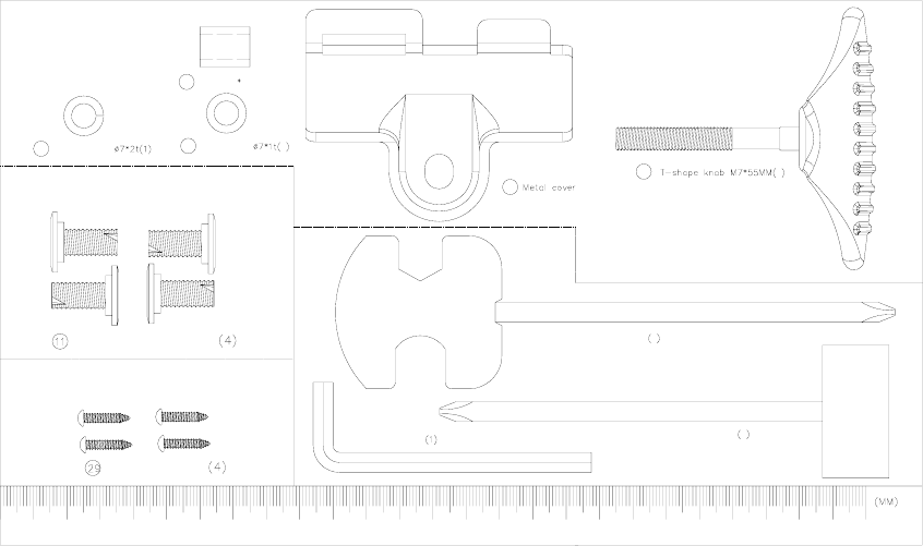
Hardware Chart
Stage#5
Stage#1
Stage#4
(Pedal Wrench)
24 Spring Washer 25 Fl at Washer 1
Allen Key
26 (1)
22 1
Screwdriver 1
Box Spanner 1
23 Bushing£ p7£p12* 15MM (1)
Screws M8xP1.25x16mm
Screws M3x14mm
Note: Please verify you have all correct parts and quantities before assembling unit.
If you are missing items, are short quantities, or have damaged components,
please contact Schwinn at 1.800.864.1270
e-mail from: Keith Weier date: 7/14/2005 page:5/16
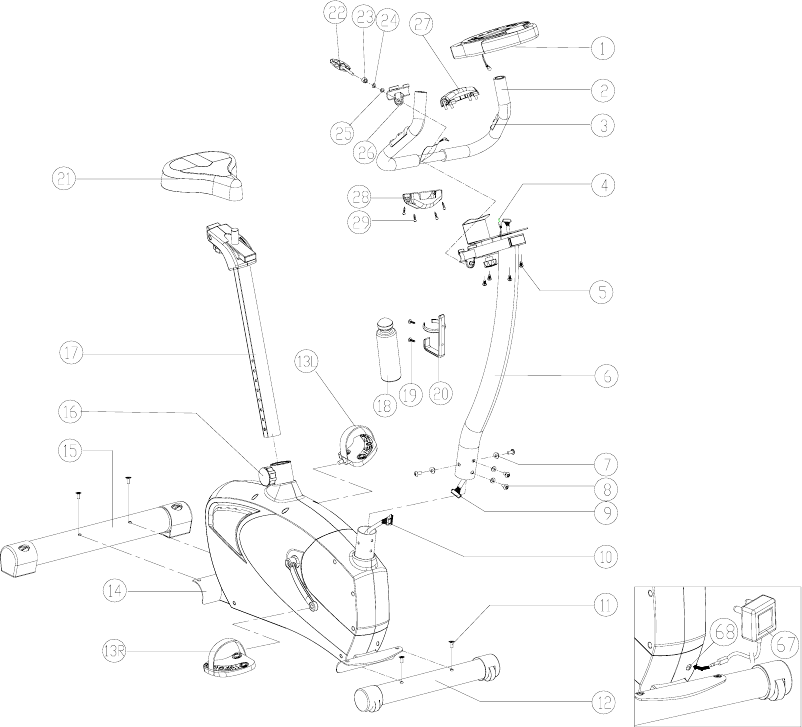
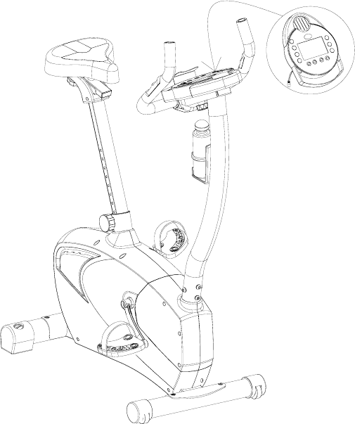
122/123 Assembly Drawing with
Reference Numbers
e-mail from: Keith Weier date: 7/14/2005 page:6/16
Replacement Parts List
Reference # Description Part #
1 Computer 18143 (112)
18142 (113)
2 Handlebar Assembly 18154
4 Upper Heart Rate Cable 18175
5 Computer Mounting Screws 18094
6 Computer/Handlebar Mast 18160
7 Curved Washers 18098
8 Allen Bolt M8 x P1.25 x 16mm 18001
9 Computer Cable (upper) 18046
11 Flat Head Screw 8x16L 18136
12 Front Stabilizer tube (w/wheels) 18153
13 Pedals 18048
15 Rear Stabilizer Tube 18159
16 Seat Post Adjustment Knob 18132
17 Seat Post 18128
18 Water Bottle 85012
19 Screw 5 x 14L 18137
20 Bottle Cage 18005
21 Seat 18103
22 T-Knob 18043
23 T-Knob Bushing 18044
24 Spring Washer 95623
25 Flat Washer 7x12x1T 30126
26 Handlebar Clamp 18124
27 Front Handlebar Cover 18172
28 Rear Handlebar Cover 18173
29 Screw M3x14L 18135
30 Adjustment Knob 18133
67 Power Plug 18007
N/A Right Shroud 18033
N/A Left Shroud 18025
Instructions
IMPORTANT!: To ensure ease of assembly please verify the size and
quantity of all the required assembly hardware and parts with the enclosed
parts list and full size hardware chart.
e-mail from: Keith Weier date: 7/14/2005 page:7/16
Each step of the assembly process has been broken down into 7 easy-to-follow
stages. Please take just a few moments to read over these instructions to
familiarize yourself with the process to make assembly quick and trouble-free.
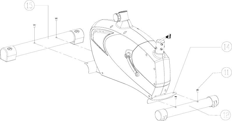
Assembly Stage #1
Attach Front and Rear Stabilizer Tubes to Main Unit
Assembly hardware required: (4) Flat Head Screw 8x16L (item #11)
1. Attach the FRONT STABILIZER TUBE (#12) to the MAIN UNIT (#14) by
inserting the two FLAT HEAD SCREWS (#11) into the holes in the stabilizer and
front of the main unit. Make sure that the wheels on the front stabilizer tube are
facing away from the main unit. Tighten bolts securely
2. Attach the REAR STABILIZER TUBE (#15) to the MAIN UNIT (#14) by
inserting the two FLAT HEAD SCREWS (#11) into the holes in the stabilizer and
rear of the main unit. Make sure that the leveler adjustments on the rear stabilizer
tube are facing up. Tighten bolts securely.
Assembly Stage #2
Attach Pedals to the Crank Arms on Main Unit
e-mail from: Keith Weier date: 7/14/2005 page:8/16
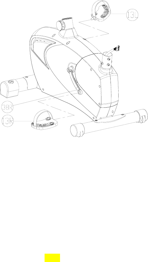
Assembly hardware required: NONE
1. Attach right PEDAL (#13R) to the right crank arm on the RIGHT CRANK
(#38R). Thread the pedal onto the crank arm and then tighten with pedal wrench.
2. Attach left PEDAL (#13L) to the left crank arm on the LEFT CRANK (#38L).
Thread the pedal onto the crank arm and then tighten with pedal wrench. Note:
There is a right pedal and a left pedal, marked by R and L. The threading
on the left pedal is reversed from the right pedal. Counterclockwise rotation
tightens while Clockwise rotation loosens on the left pedal. To avoid
stripping of the threads be careful to use the proper pedal.
3. Attach PEDAL STRAPS (#28) to each PEDAL (#13). Again each strap is labeled
with an R or an L corresponding to the right and left pedal straps.
Assembly Stage #3
Attach Seat Post, Slider, and Pad to Main Unit
e-mail from: Keith Weier date: 7/14/2005 page:9/16
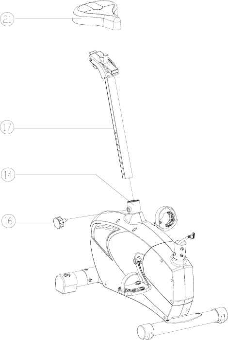
Assembly Hardware Required: NONE
1. Insert SEAT POST (#17) into corresponding hole in MAIN UNIT (#14). Tighten
down with SEAT POST ADJUSTMENT KNOB. (#16).
2. Insert SEAT (#21) onto SEAT SLIDER (#17). Tighten bolt on underside of the
seat with a wrench until seat no longer twists or tilts.
3. Seat Adjustment: Adjust the seat height by unscrewing seat post adjustment knob
and tightening into appropriate adjustment hole on the seat post. Leg should be
almost fully extended at the bottom of the pedal stroke. Fore and Aft seat position
can be adjusted with the seat slider knob. If the seat wobbles make sure that both
knobs (#16 and #30) are fully tightened.
e-mail from: Keith Weier date: 7/14/2005 page:10/16
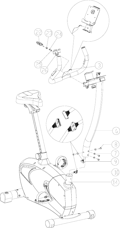
Assembly Stage #4
Attach Computer/Handlebar Mast to Main Unit. Attach Handlebar
Assembly to Computer/Handlebar Mast.
Assembly Hardware Required: (4) M8 Allen Bolt 16mm (item #8)
(already on main unit)
(4) Curved Washers (item #17)
(Already on main unit)
(1) T-Knob (item #22)
(1) T-Knob Bushing (item #23)
(1) Spring Washer (item #24)
(1) Flat Washer 7x12x1T (item #25)
e-mail from: Keith Weier date: 7/14/2005 page:11/16
1. Attach the LOWER COMPUTER CABLE (#10) from the MAIN UNIT (#14) to
the UPPER COMPUTER CABLE (#9) from the bottom of the
COMPUTER/HANDLEBAR MAST (#6).
2. Slide the COMPUTER/HANDLEBAR MAST (#6) onto the MAIN UNIT (#14).
3. Fasten the COMPUTER HANDLEBAR MAST to the MAIN UNIT with the
8mm BOLTS (#8) and CURVED WASHERS (#7) and tighten.
4. Place HANDLEBAR ASSEMBLY (#2) in the groove on the
COMPUTER/HANDLEBAR MAST (#6) and place HANDLEBAR CLAMP
(#26) over the top of the middle of the HANDLEBAR (#2) aligning the steel tabs
inside the receiver holes. Fasten with the T-KNOB (#22), T-KNOB BUSHING
(#23), SPRING WASHER (#10), and WASHER (#11).
5. Attach HR CABLE extending from the HANLBARS (#2) into the Jack on the
COMPUTER/HANDLEBAR MAST ASSEMBLY (#6).
e-mail from: Keith Weier date: 7/14/2005 page:12/16
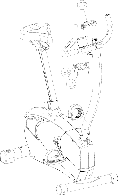
Assembly Stage #5
Attach Handlebar Cover to Handlebar Assembly.
Assembly Hardware Required: (4) Screws M3x14L (item#29)
1. Attach FRONT HANDLEBAR COVER (#27) and the REAR HANDLEBAR
COVER (#28) around the HANDLEBAR ASSEMBLY (#2) using 4 SCREWS
(#29).
e-mail from: Keith Weier date: 7/14/2005 page:13/16
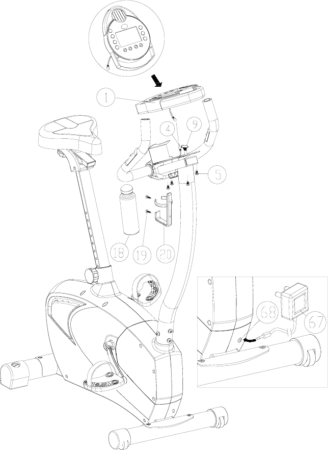
Assembly Stage #6
Attach Computer Console to Computer/Handlebar Mast & Water
Bottle Cage
Assembly Hardware Needed: (4) Computer Screws (item #5)
(Already attached to computer)
(2) Screw 5x14L (item#19)
1. Attach UPPER COMPUTER CABLE (#9) exiting top of
COMPUTER/HANDLEBAR MAST (#6) to the bottom of the COMPUTER (#1).
e-mail from: Keith Weier date: 7/14/2005 page:14/16
2. Place the COMPUTER (#1) on top of the COMPUTER/HANDLEBAR MAST
(#6). The reading rack should wrap around the bottom of the computer console.
3. Attach the COMPUTER to the COMPUTER/HANDLEBAR MAST with the 4
COMPUTER MOUNTING SCREWS (#4).
4. Fasten WATER BOTTLE CAGE (#20) to COMPUTER SUPPORT TUBE (#6)
with the two WATER BOTTLE SCREWS (#19) and tighten screws.
5. Insert WATER BOTTLE (#18) into WATER BOTTLE CAGE.
6. Insert the POWER PLUG (#67) into the wall and the other end into the POWER
INPUT (#68) located at the rear of the MAIN UNIT (#14) just above the FRONT
STABILIZER TUBE (#12)
That’s it!
You’re finished and now you can begin to reach your fitness goals!
Please reference the Owner’s Manual for information regarding computer
operation, product maintenance, Warranty information, and general fitness and
exercise guidelines.
Schwinn Customer Service
1.800.864.1270
e-mail from: Keith Weier date: 7/14/2005 page:15/16
Troubleshooting the Schwinn 122/123 Upright
Exercise Bike
TIP: Use assembly diagram(s) as reference when troubleshooting unit.
PROBLEM: Computer will not start, function, or is blank…
(SOLUTION): 1. Ensure the batteries were installed correctly.
2. Check the wiring connections and connector orientation
made to the computer.
3. Confirm that wiring (cable assembly) has not been
damaged
4. If computer still fails to start please call 1.800.864.1270
for assistance.
PROBLEM: No Heart Rate on computer…
(SOLUTION): 1. Check the connections made at the computer and
handlebars
2. If heart rate still fails to work call 1.800.864.1270 for
assistance.
PROBLEM: Bike will not sit level…
(SOLUTION): 1. Adjust the levelers on the rear stabilizer.
Note: If you need additional support information or assistance in troubleshooting,
please contact us at: 1.800.864.1270
e-mail from: Keith Weier date: 7/14/2005 page:16/16
