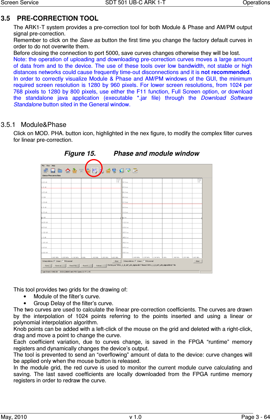
Screen Service Broadcasting Technologies SDT501UBCARK1T 200 Watt Multimode SDR Transmitter User Manual Part Three
Screen Service Broadcasting Technologies SpA 200 Watt Multimode SDR Transmitter Part Three
Contents
- 1. User Manual Part One
- 2. User Manual Part Two
- 3. User Manual Part Three
User Manual Part Three
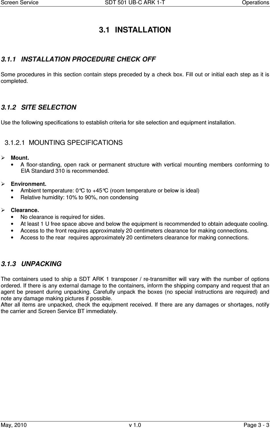


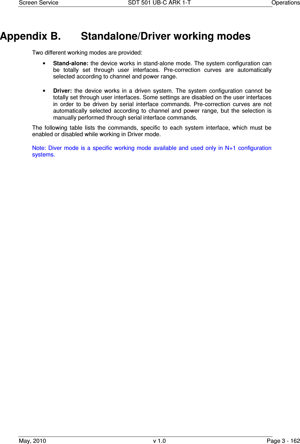
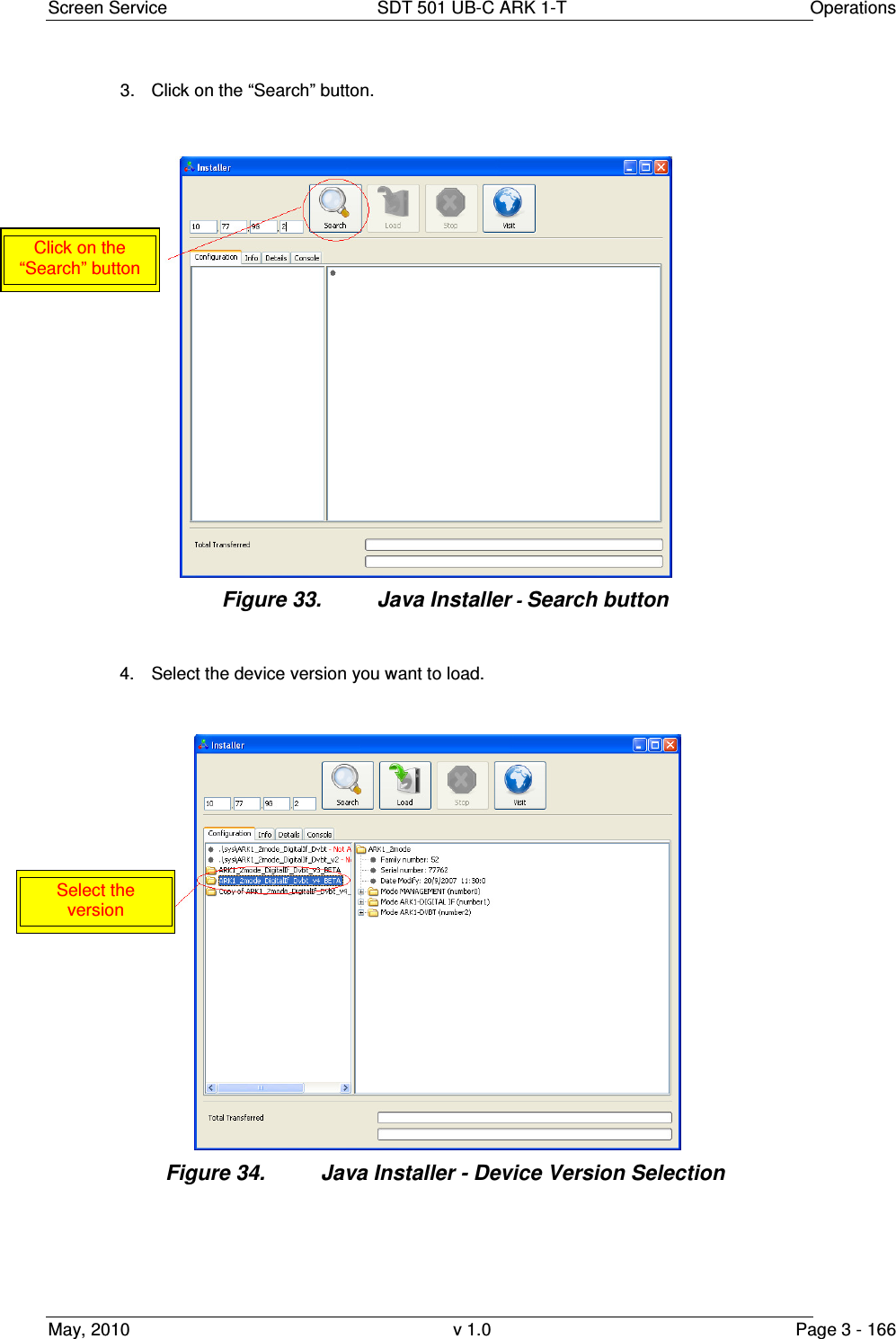
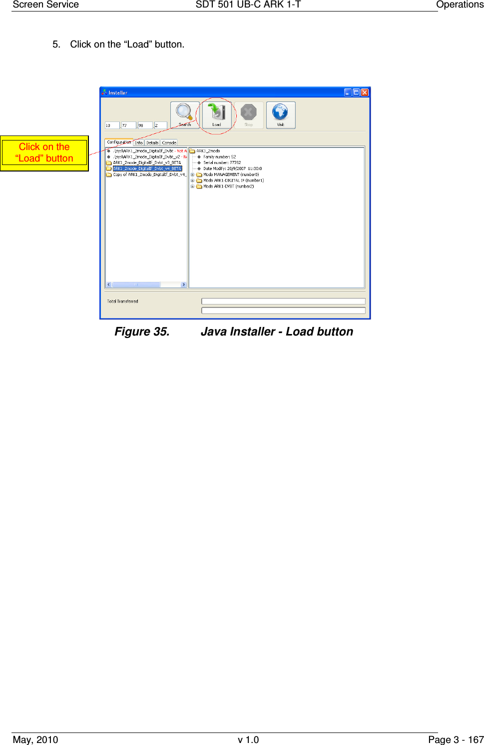
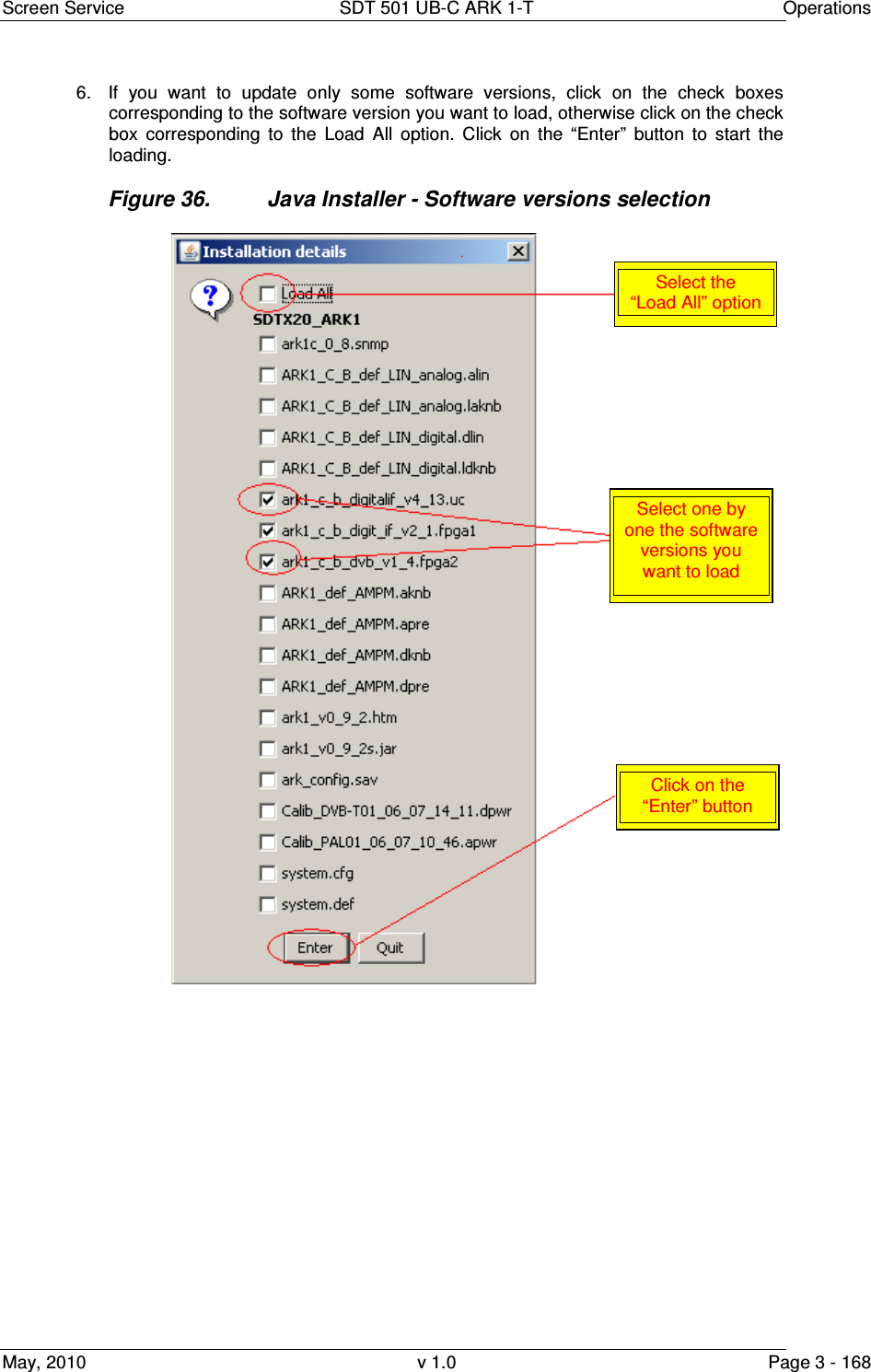
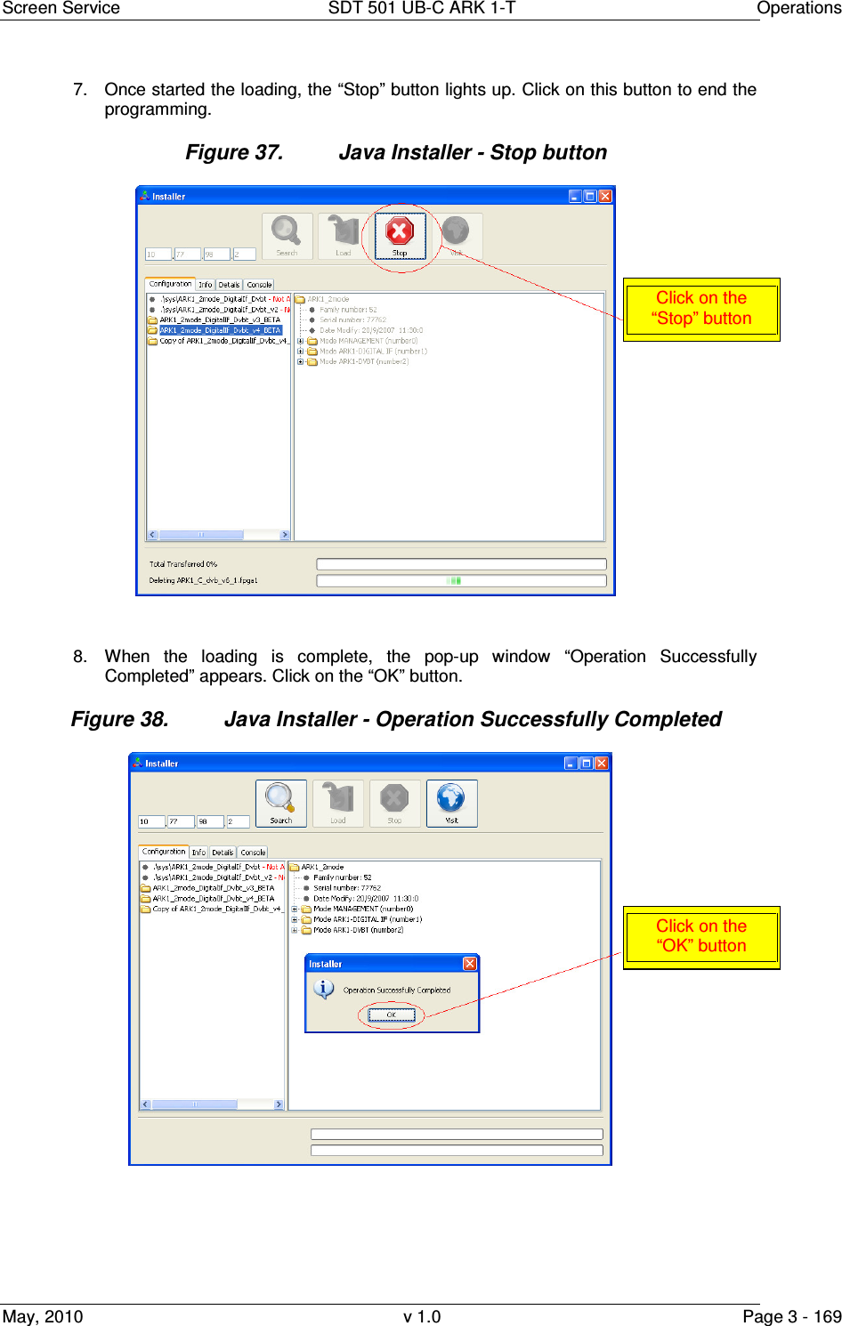
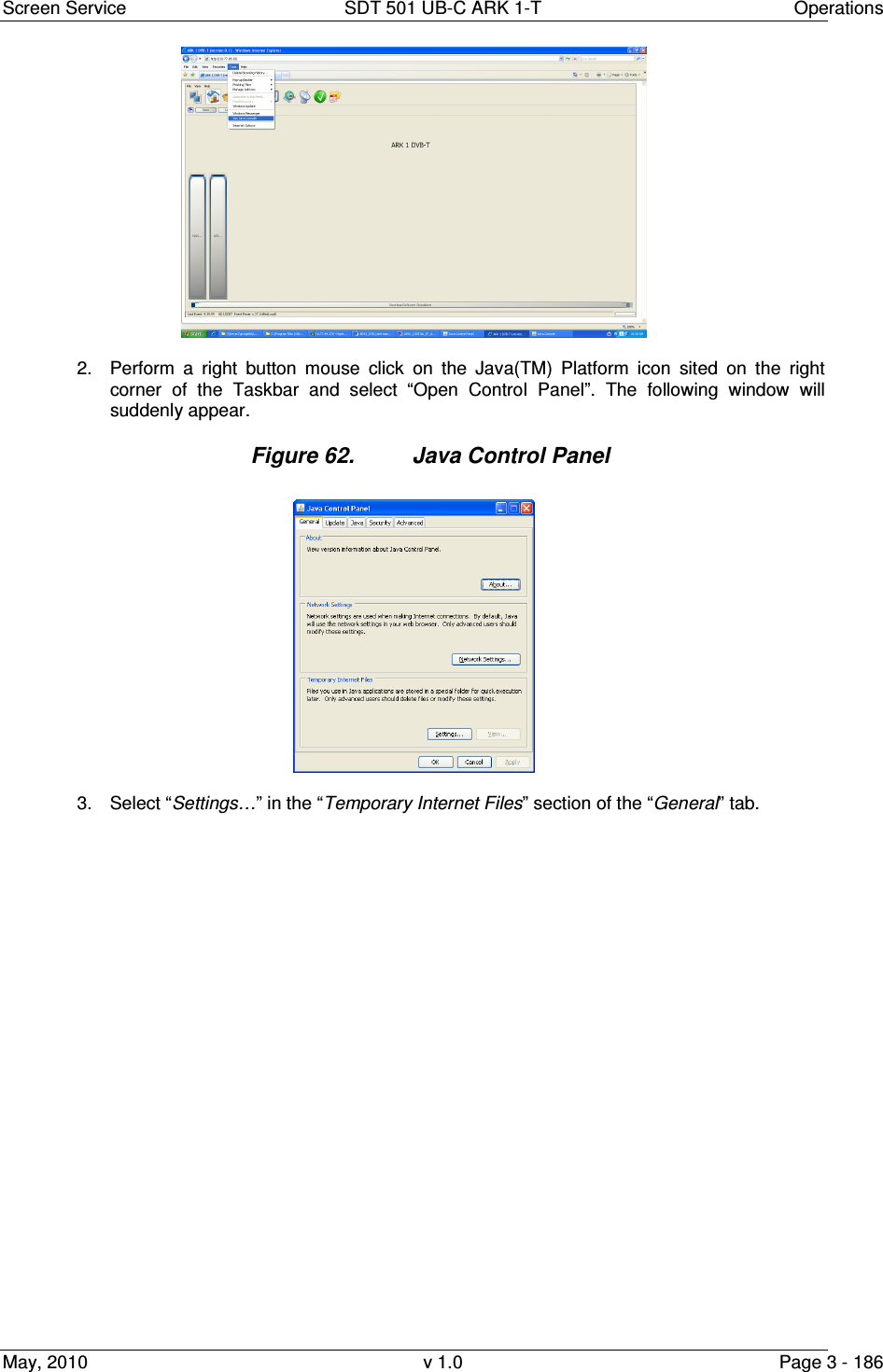
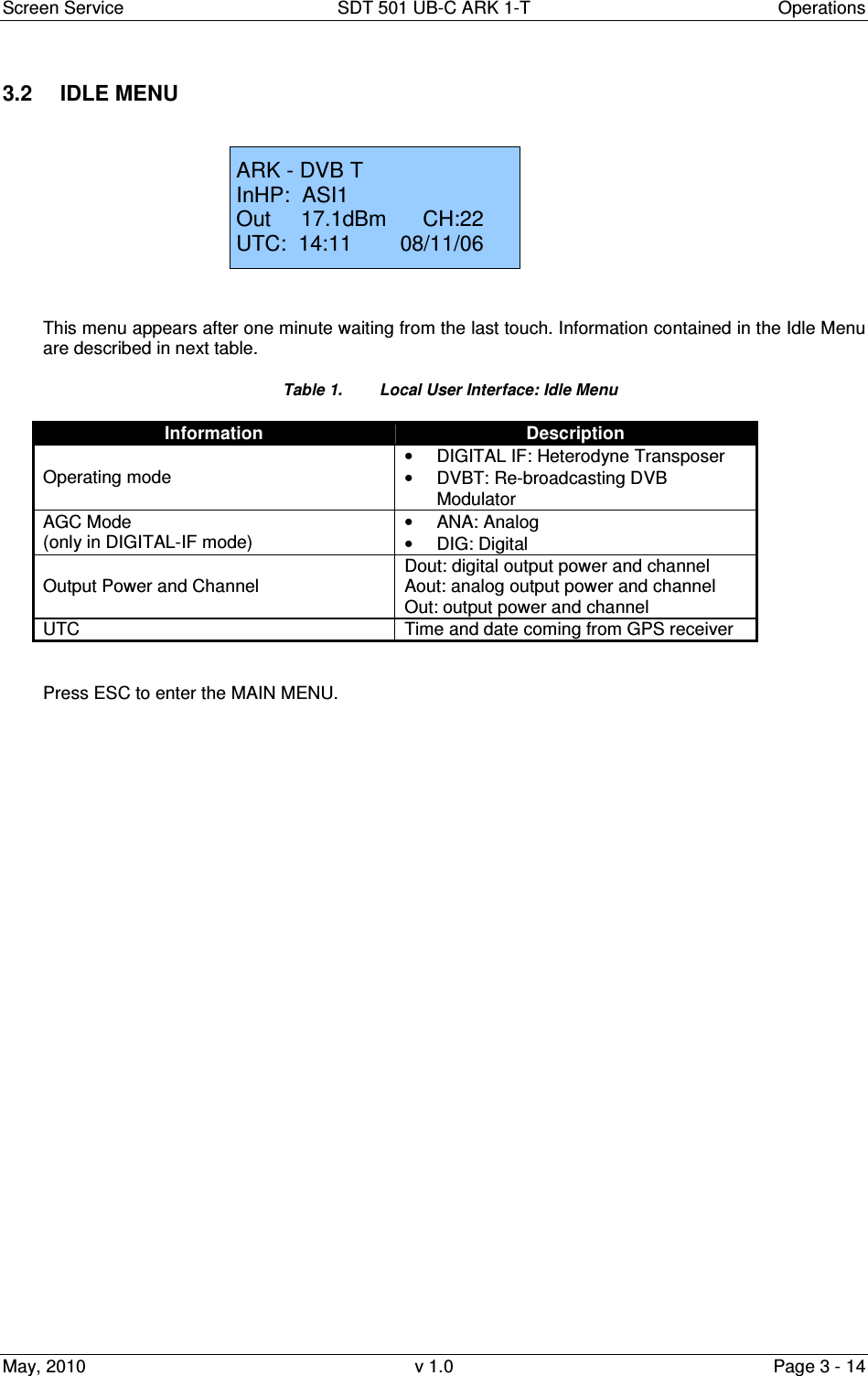
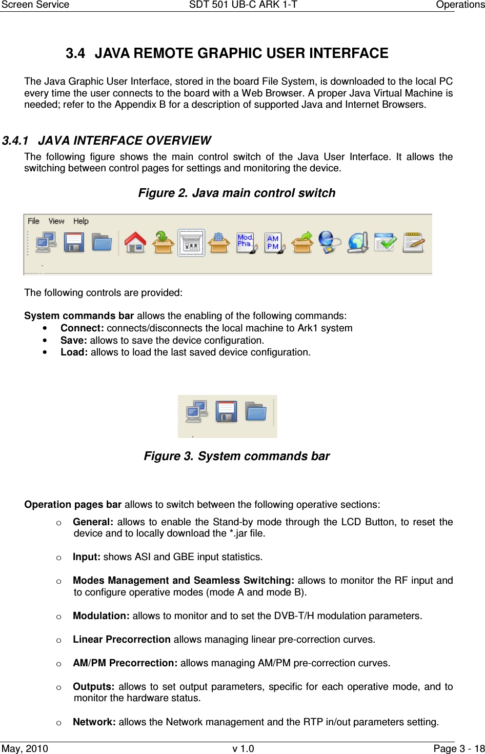
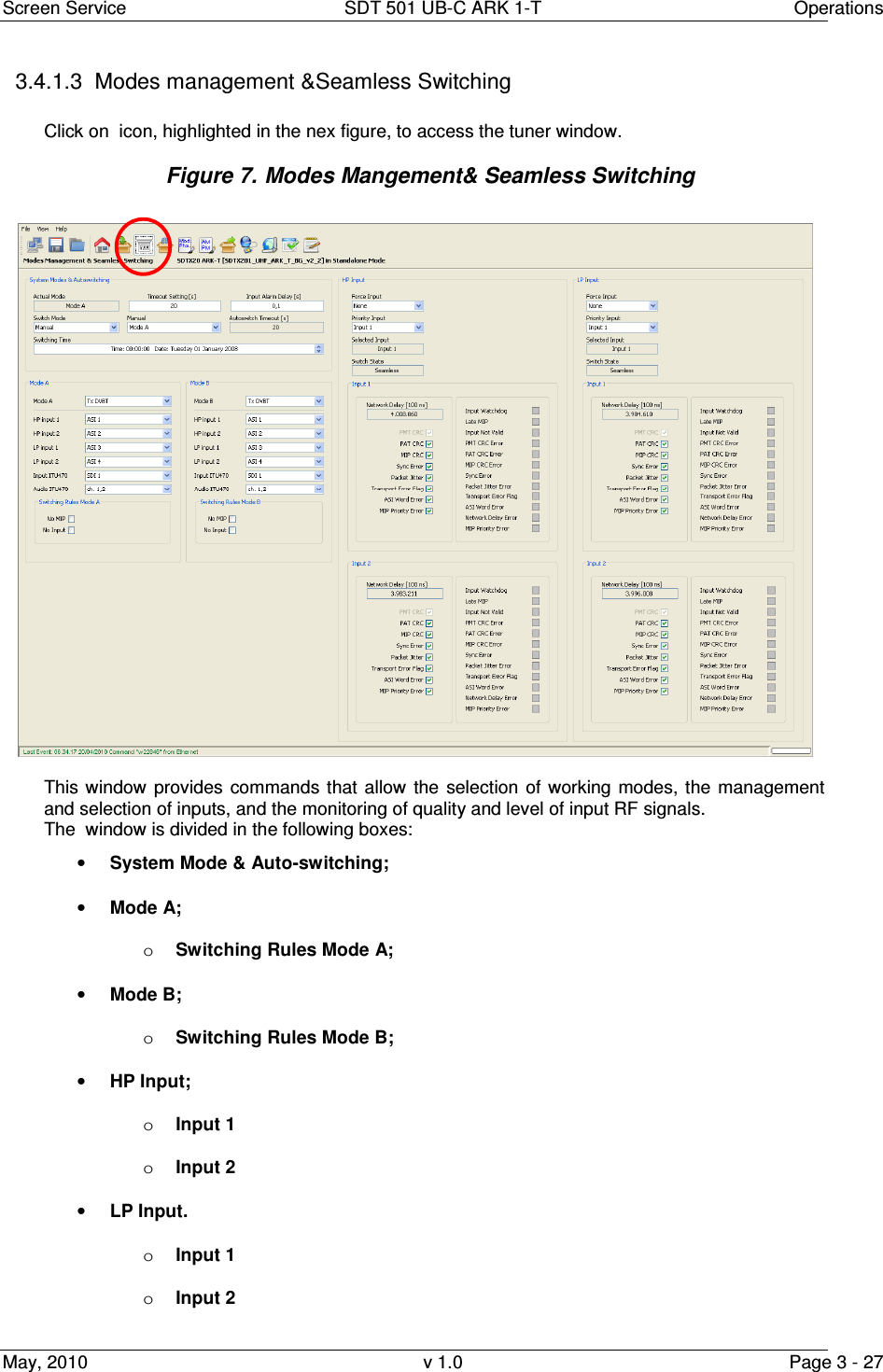
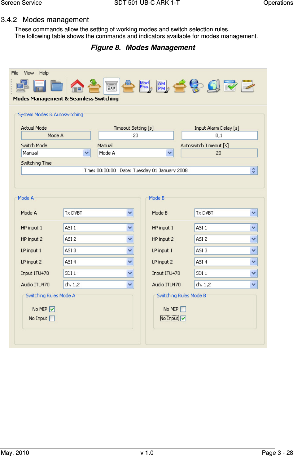
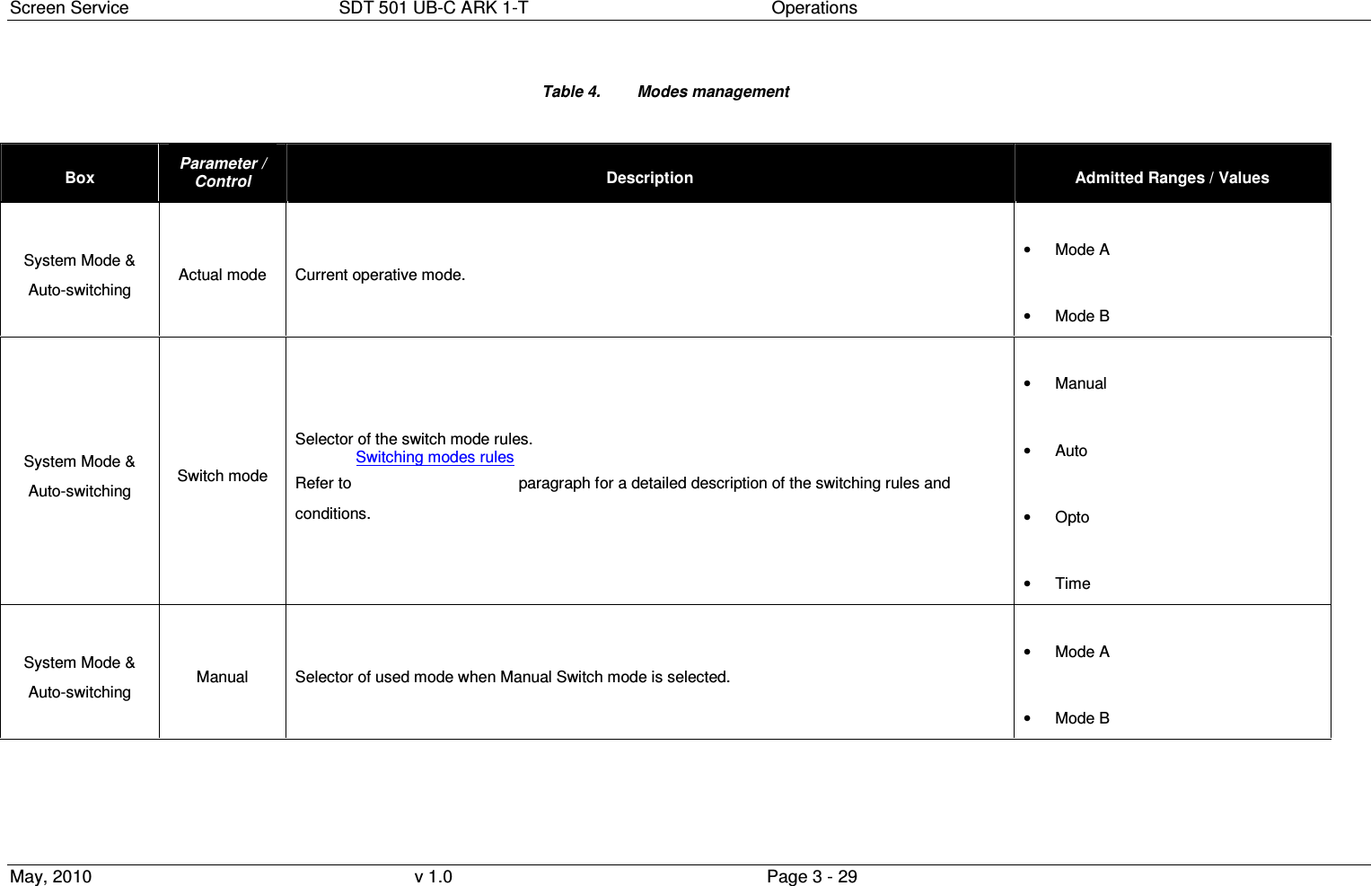
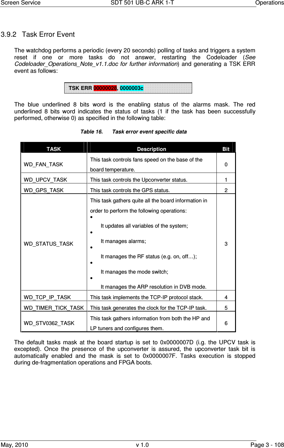
![Screen Service SDT 501 UB-C ARK 1-T Operations May, 2010 v 1.0 Page 3 - 13 Figure 1. Local Interface Menu Tree 3.1.8 BOOT AND WELCOME MESSAGE Turning on the equipment, the display shows the progress bar as follow: When the boot is over, the board is ready. Press ESC to enter the main menu, otherwise after one minute waiting the idle status message appears.Screen ServiceARK - DVB-T/DIG-IFSystem InitInit : [ ] WaitScreen ServiceARK - DVB-T/DIG-IFBoot FPGAInit : [ ] WaitScreen ServiceARK - DVB-T/DIG-IFUp Converter checkInit : [ ] WaitScreen ServiceARK - DVB-T/DIG-IFStart systemInit : [ ] WaitScreen ServiceARK - DVB-T/DIG-IFStart systemInit : [ ] ReadyScreen ServiceARK - DVB-T/DIG-IF10.77.98.44 Ready](https://usermanual.wiki/Screen-Service-Broadcasting-Technologies/SDT501UBCARK1T.User-Manual-Part-Three/User-Guide-1390839-Page-13.png)
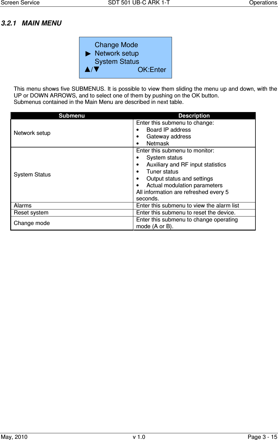
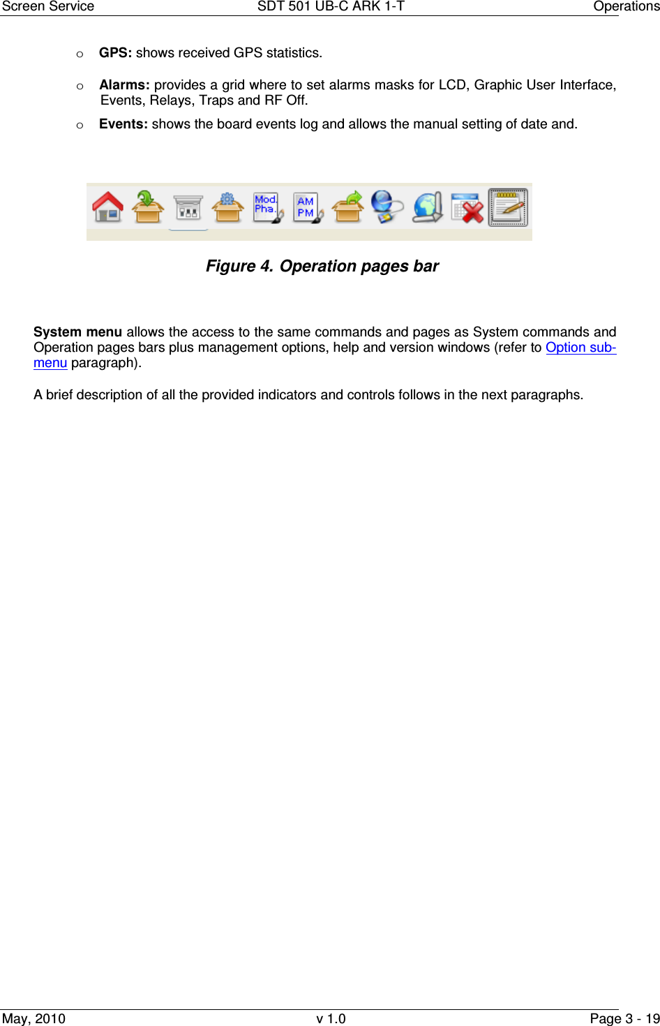
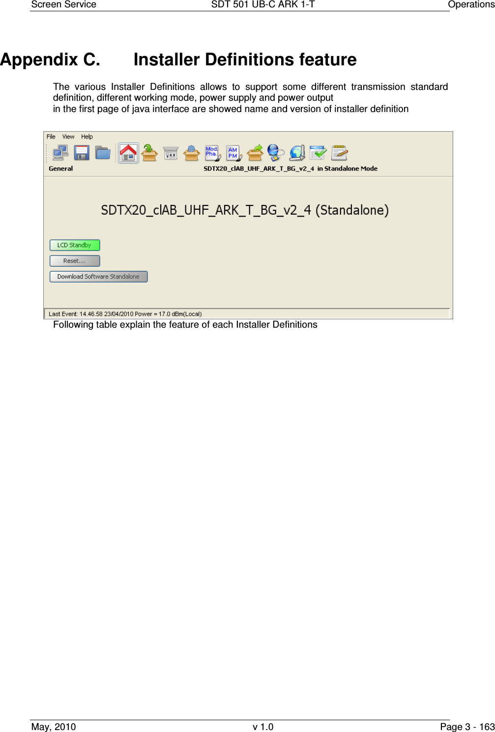
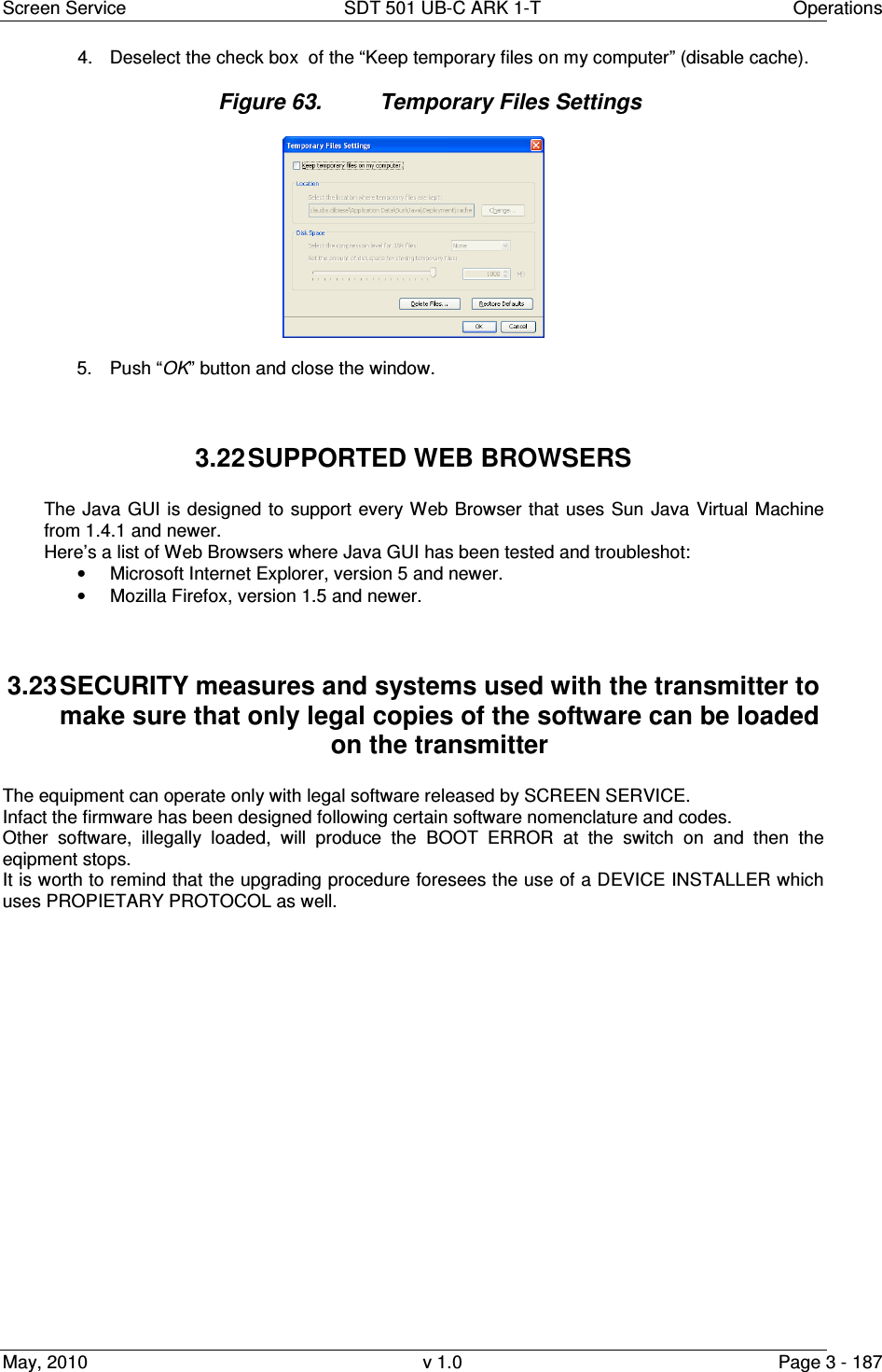
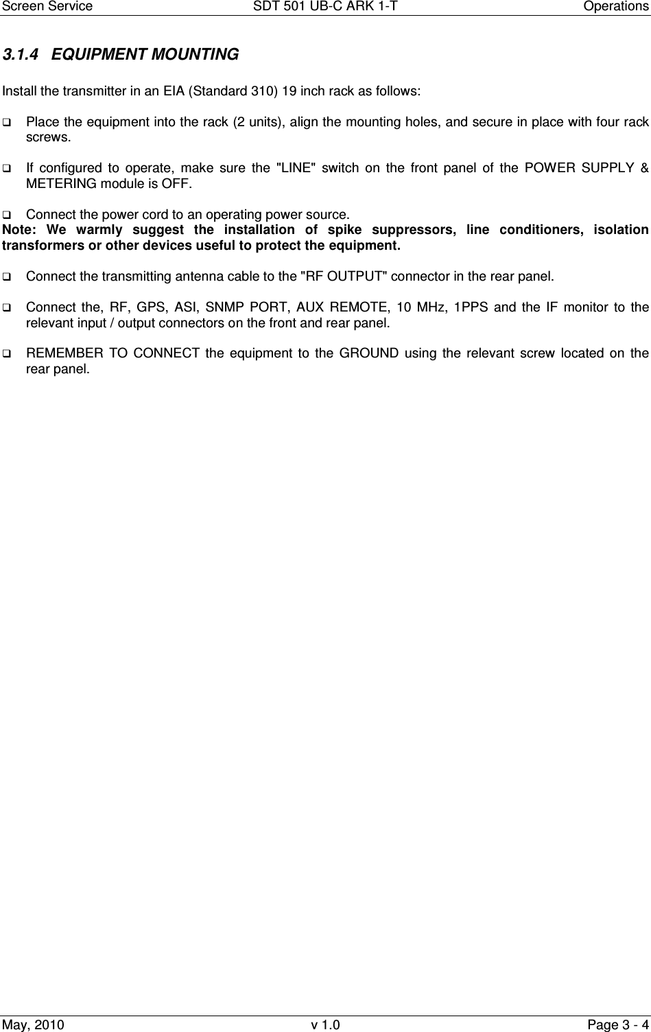
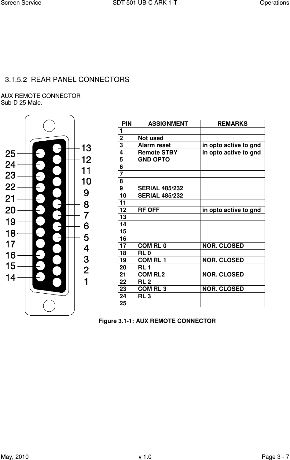
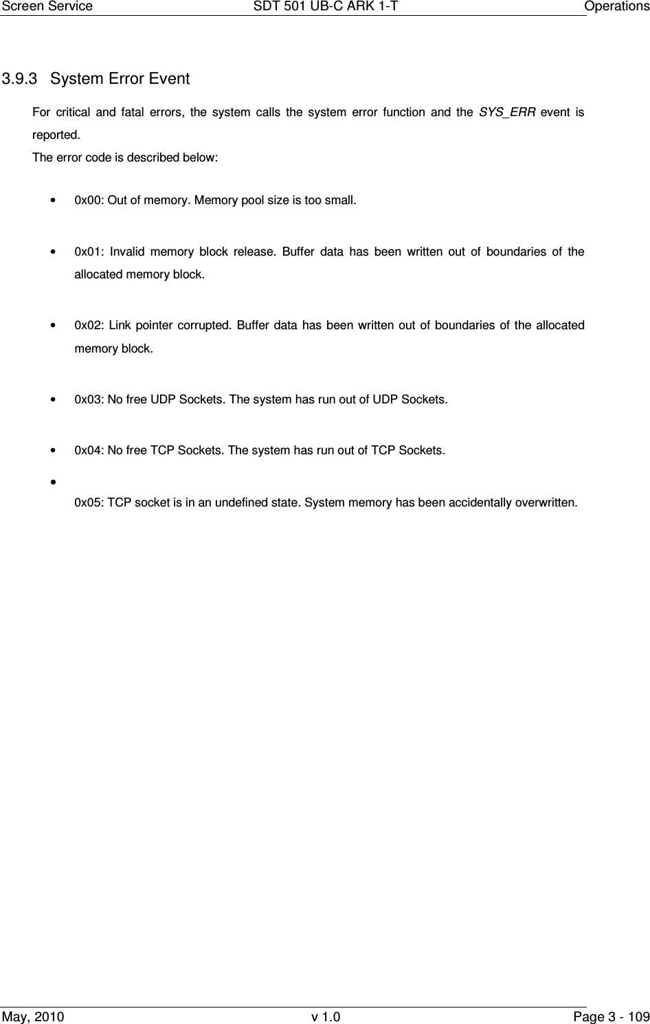
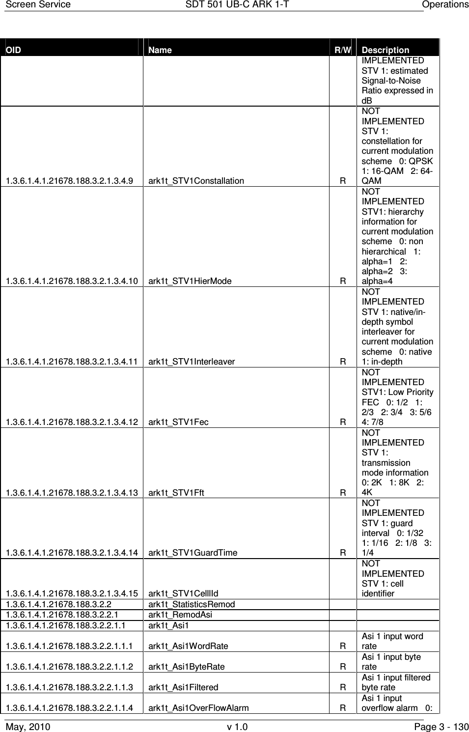
![Screen Service SDT 501 UB-C ARK 1-T Operations May, 2010 v 1.0 Page 3 - 23 Table 3. Input window Box Parameter / Control Description Admitted Ranges / Values ASI Word rate ASI input word rate. 10 bits word rate of ASI input (Ref. to CEI EN 50083-9). Approximately 27 Mword/s ASI Bit-rate [bit/s] ASI input bit-rate. ASI Filtered bit-rate[bit/s] When the ARK-T working in seamless mode the java show the filtered bit-rate of all seamless input (seamless mode working in SFN mode only, so the bit-rate actually used by the modulator, and the filtered bit-rate showed must be equal than the total bit-rate) When the seamless mode is disabled the java show the bit-rate actually used by the modulator. • Zero when the input has not been selected • Equal to the total bit-rate, when Delete Null Packets disabled • Less than total bit-rate, when Delete Null Packets enabled ASI Format Format of received TS Packets (Ref. to CEI EN 50083-9). • 188 Bytes • 240 Bytes ASI CD ASI Carrier detect. • Green: Detected • Grey: Not detected](https://usermanual.wiki/Screen-Service-Broadcasting-Technologies/SDT501UBCARK1T.User-Manual-Part-Three/User-Guide-1390839-Page-23.png)
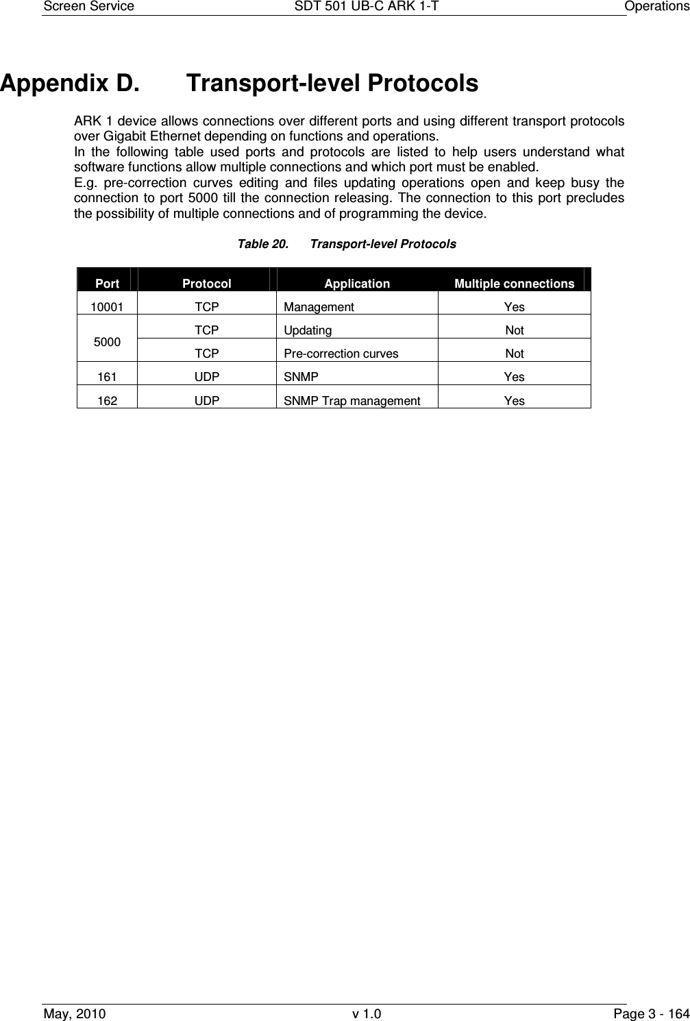
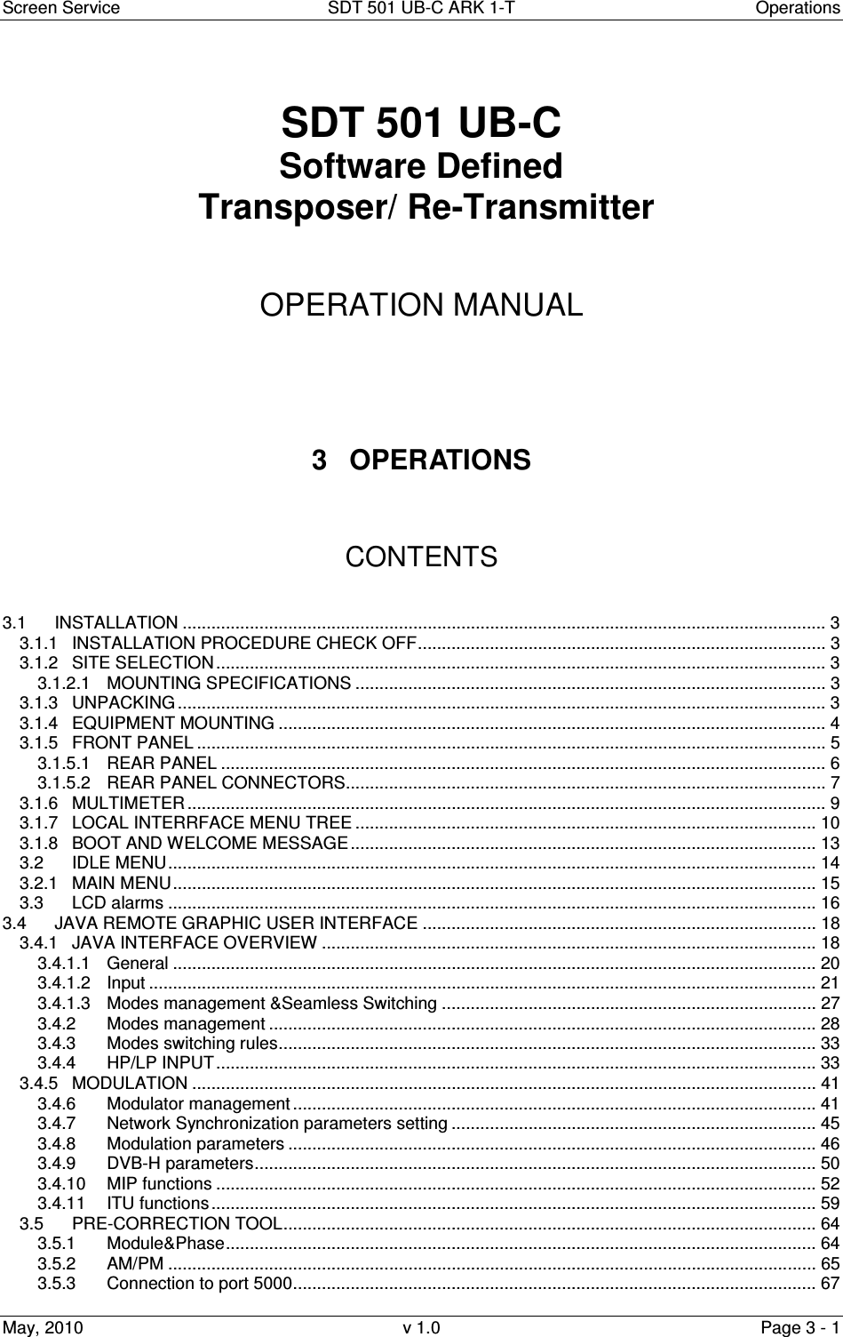
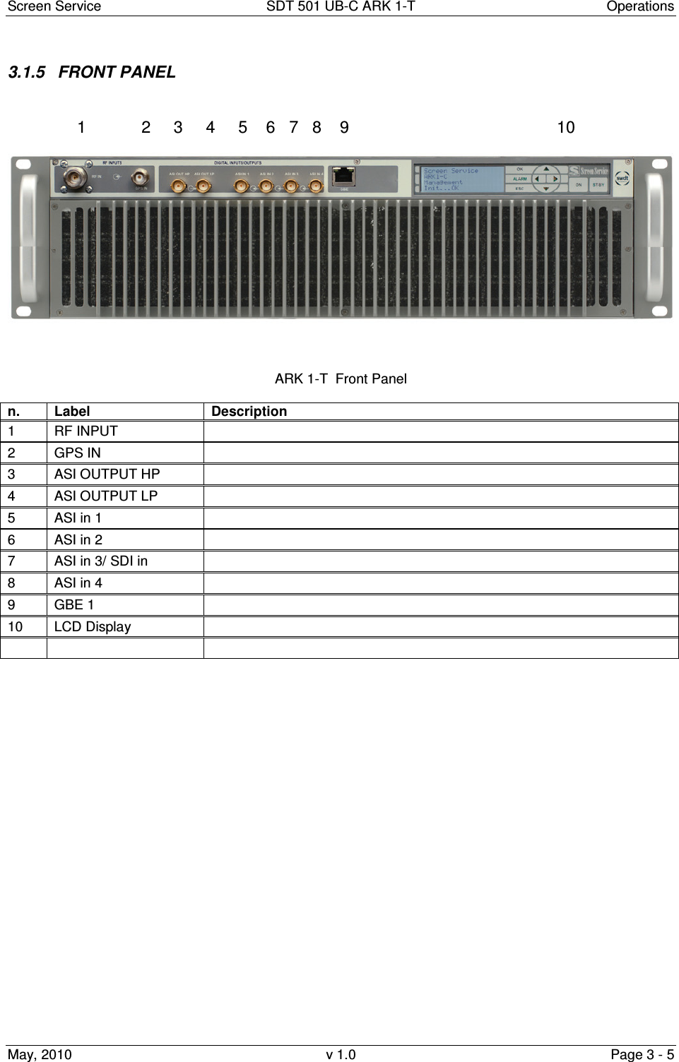
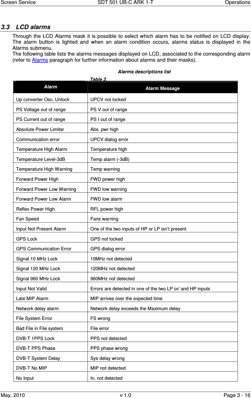
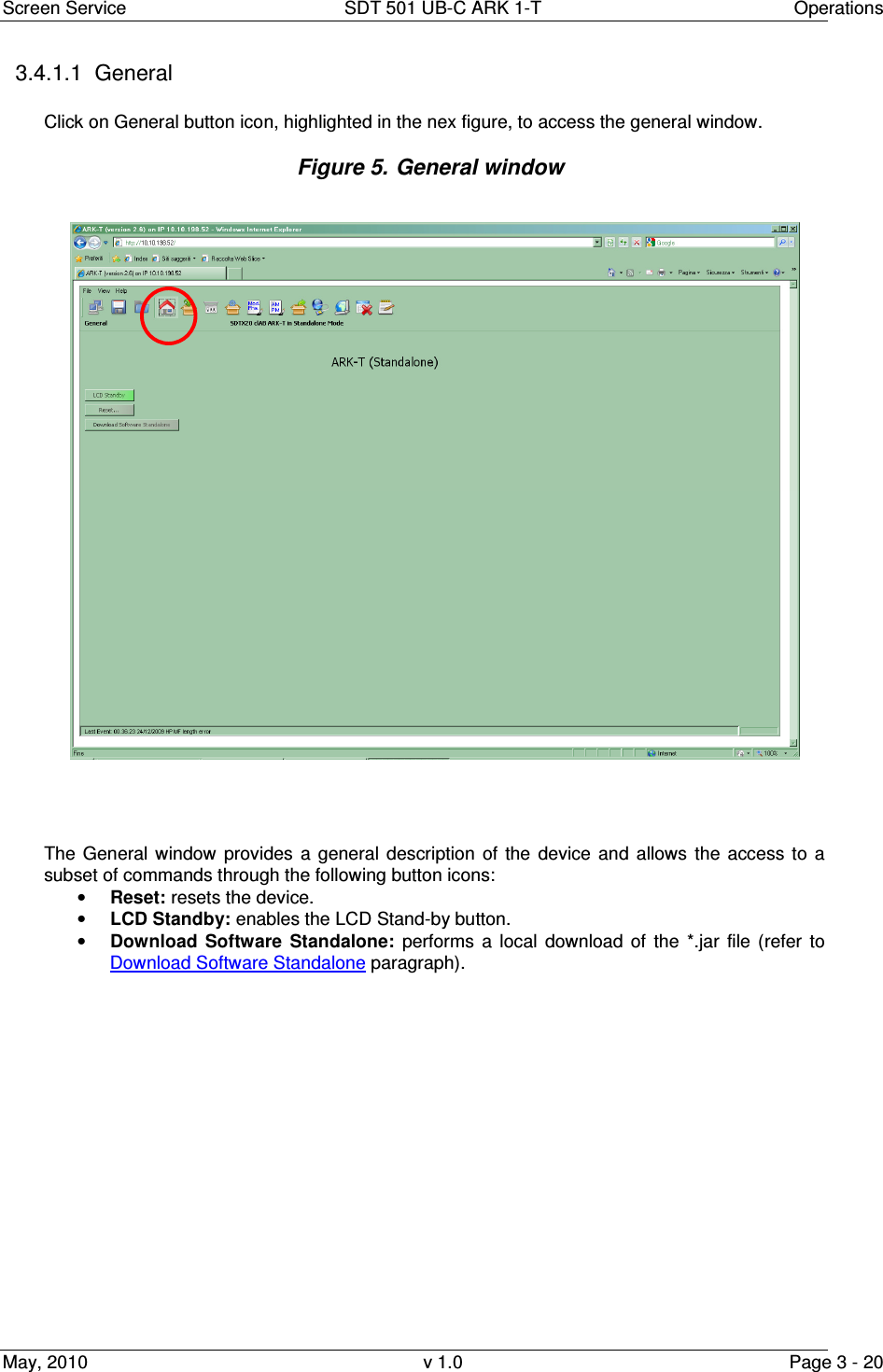
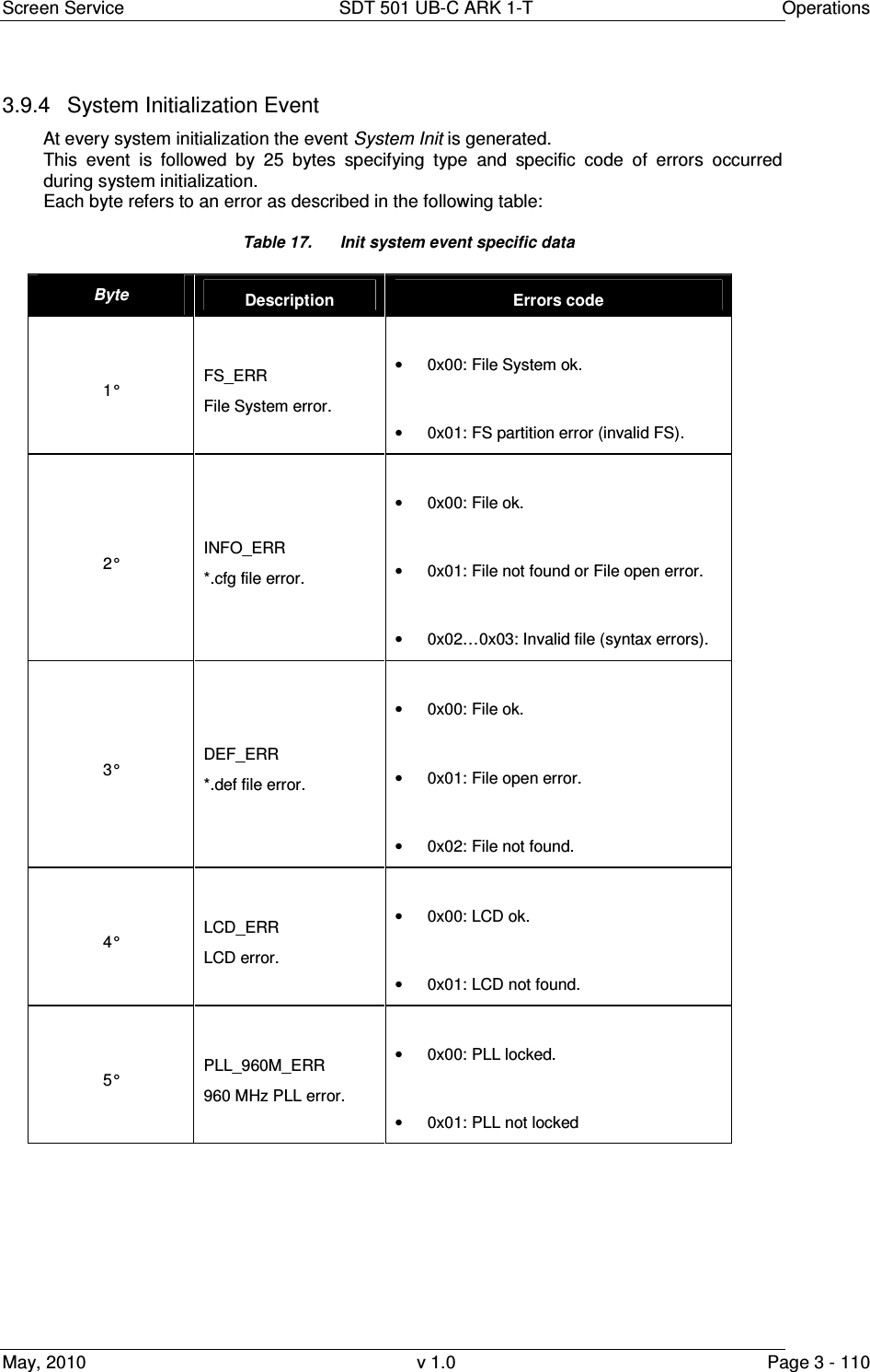
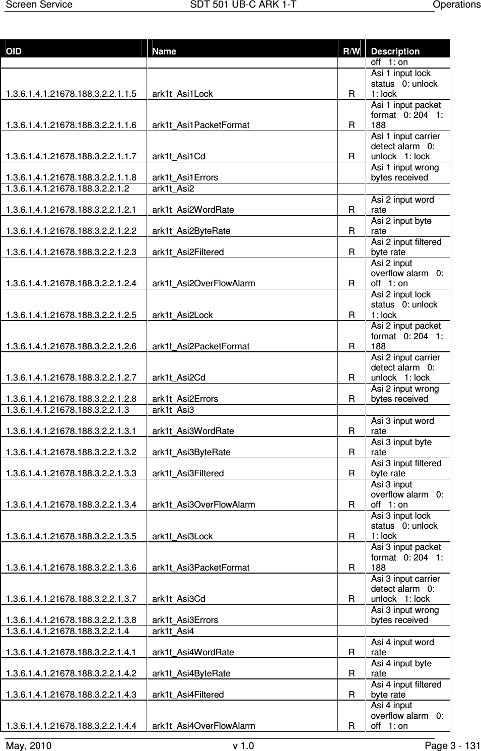
![Screen Service SDT 501 UB-C ARK 1-T Operations May, 2010 v 1.0 Page 3 - 24 Box Parameter / Control Description Admitted Ranges / Values ASI Lock ASI locking status. The input Transport Stream is unlocked when more than two consecutive Sync Byte are missed then five consecutive Sync Bytes must occur to regain the lock (Ref. to ETSI ETR-291) • Green: Locked • Grey: Not locked ASI Overflow ASI input overflow indicator. This alarm condition occurs when the input bit-rate exceeds the capability of the modulation (Ref. to ETSI EN 300 744). • Red: Alarm • Grey: No alarms ASI Word Errors Total amount of ASI wrong words received. ASI/SDI Equalizer Bypass Enable/Disable the equalization bypass of the signal received over ASI interface • Checked: Enabled • Not checked: Disabled RTP Protocol Ethernet input packets protocol. • UDP • RTP RTP Bit-rate [bit/s] Bit-rate of TS from Ethernet input.](https://usermanual.wiki/Screen-Service-Broadcasting-Technologies/SDT501UBCARK1T.User-Manual-Part-Three/User-Guide-1390839-Page-24.png)
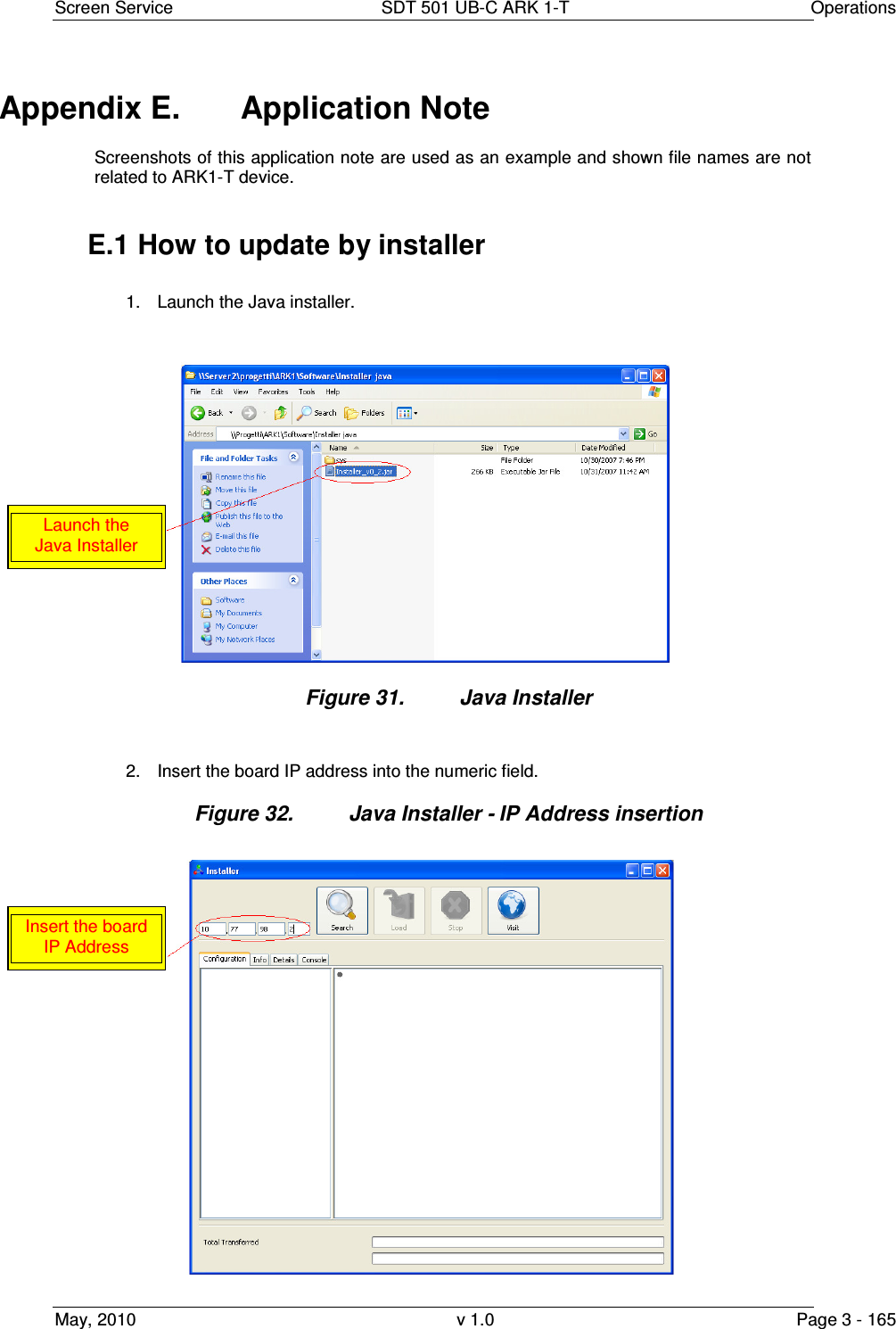
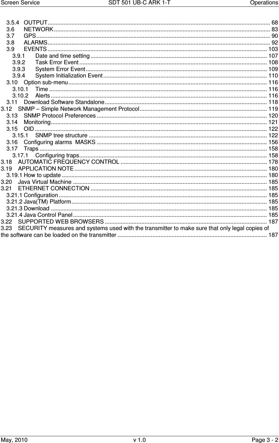
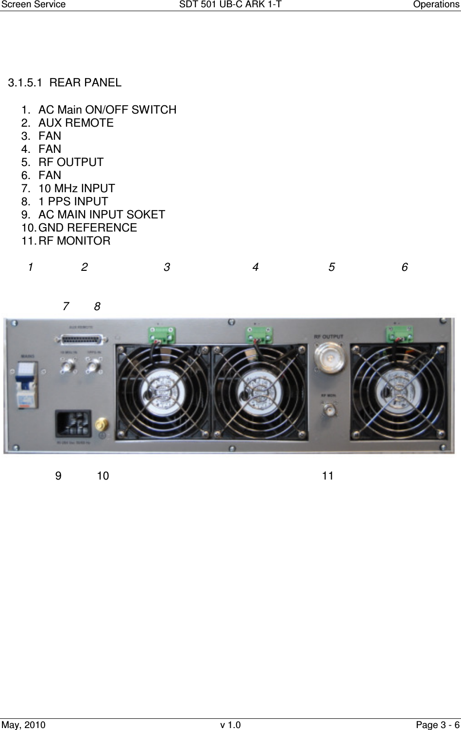
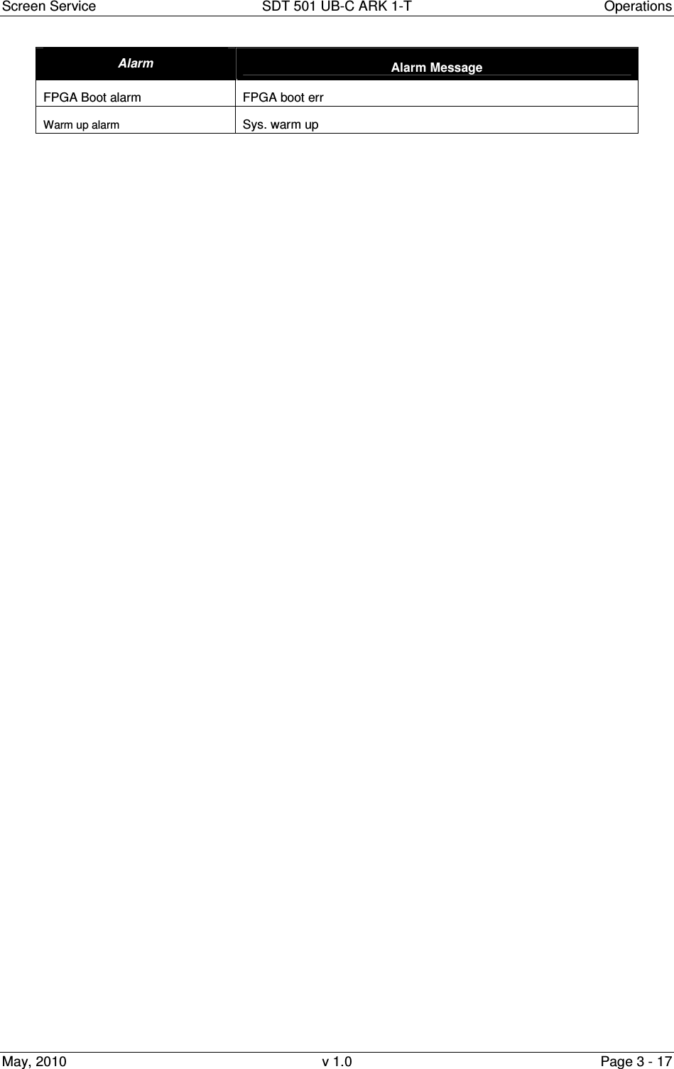
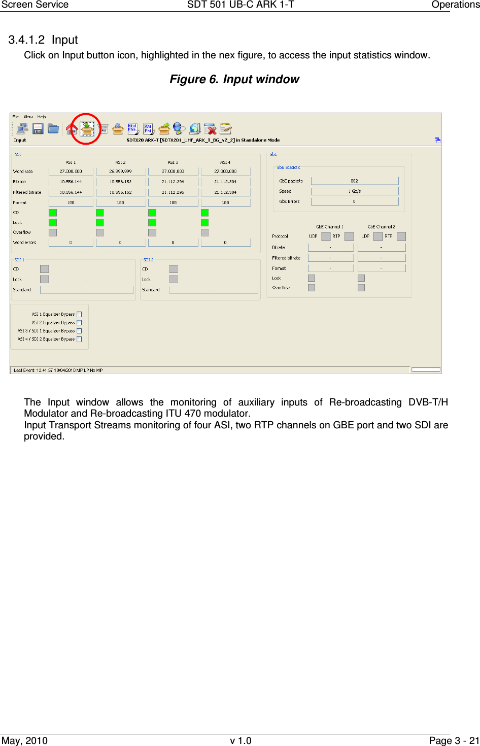
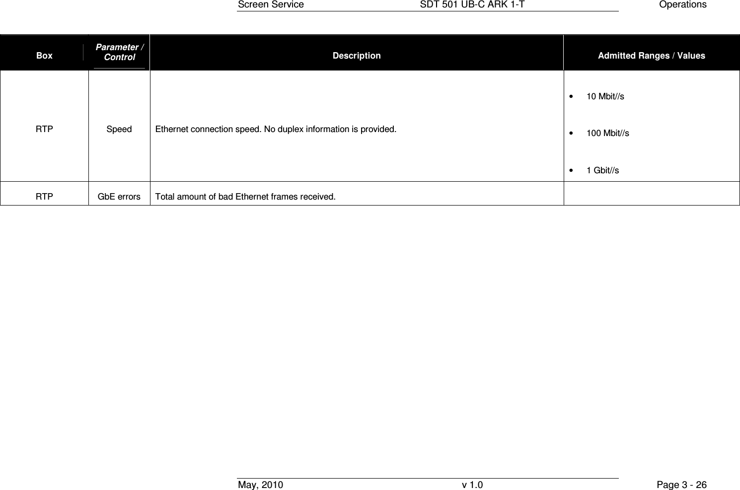
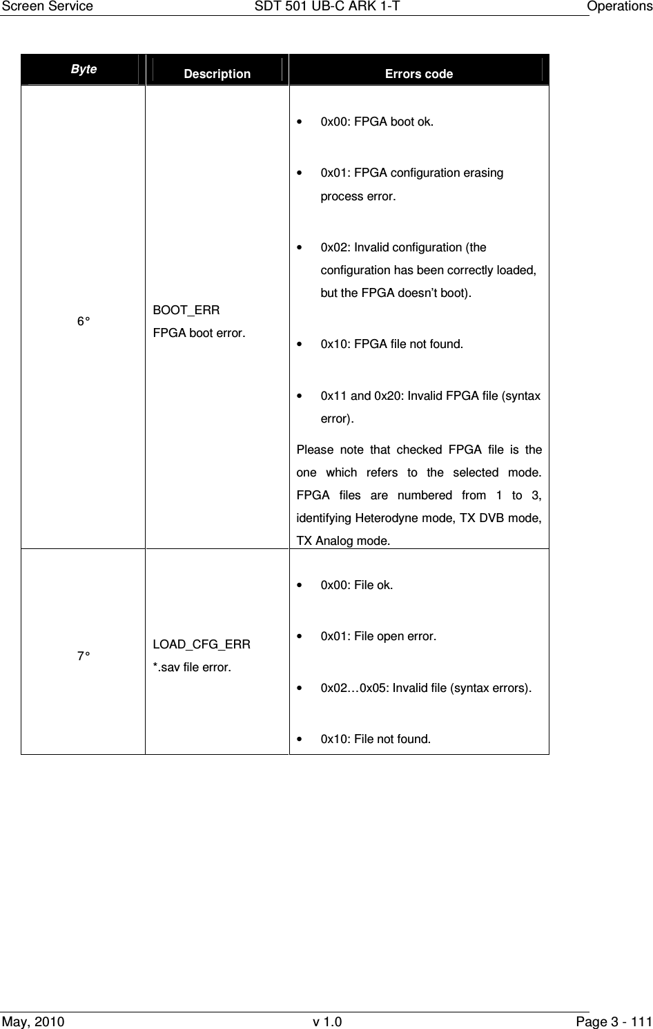
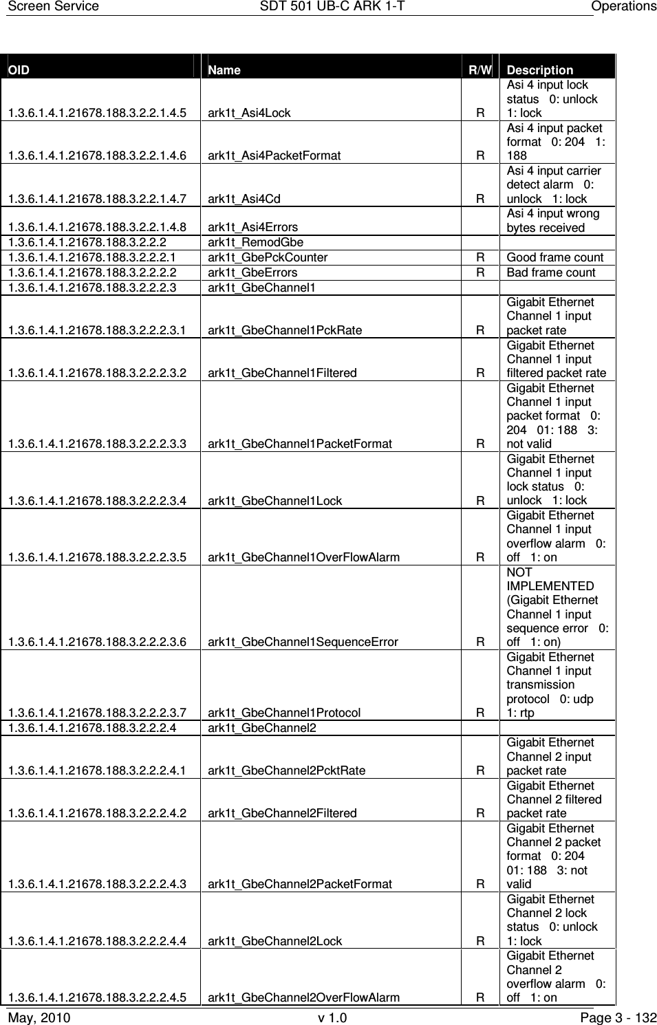
![Screen Service SDT 501 UB-C ARK 1-T Operations May, 2010 v 1.0 Page 3 - 25 Box Parameter / Control Description Admitted Ranges / Values RTP Filtered bit-rate [bit/s] Bit-rate actually used by the modulator. • Zero when the input is not selected • Equal to the total bit-rate, when Delete Null Packets disabled • Less than total bit-rate, when Delete Null Packets enabled RTP Format Format of received TS Packets (Ref. to CEI EN 50083-9). • 188 Bytes • 204 Bytes RTP Lock Transport Stream locking status. The input Transport Stream is unlocked when more than two consecutive Sync Byte are missed; then five consecutive Sync Bytes must occur to regain the lock (Ref. to ETSI ETR-291) • Green: Locked • Grey: Not locked RTP Overflow Input GbE overflow alarm status. This alarm condition occurs when the input bit-rate exceeds the capability of the modulation (Ref. to ETSI EN 300 744). • Red: Alarm on • Grey: Alarm off RTP GbE packets Total amount of good Ethernet frames received.](https://usermanual.wiki/Screen-Service-Broadcasting-Technologies/SDT501UBCARK1T.User-Manual-Part-Three/User-Guide-1390839-Page-25.png)
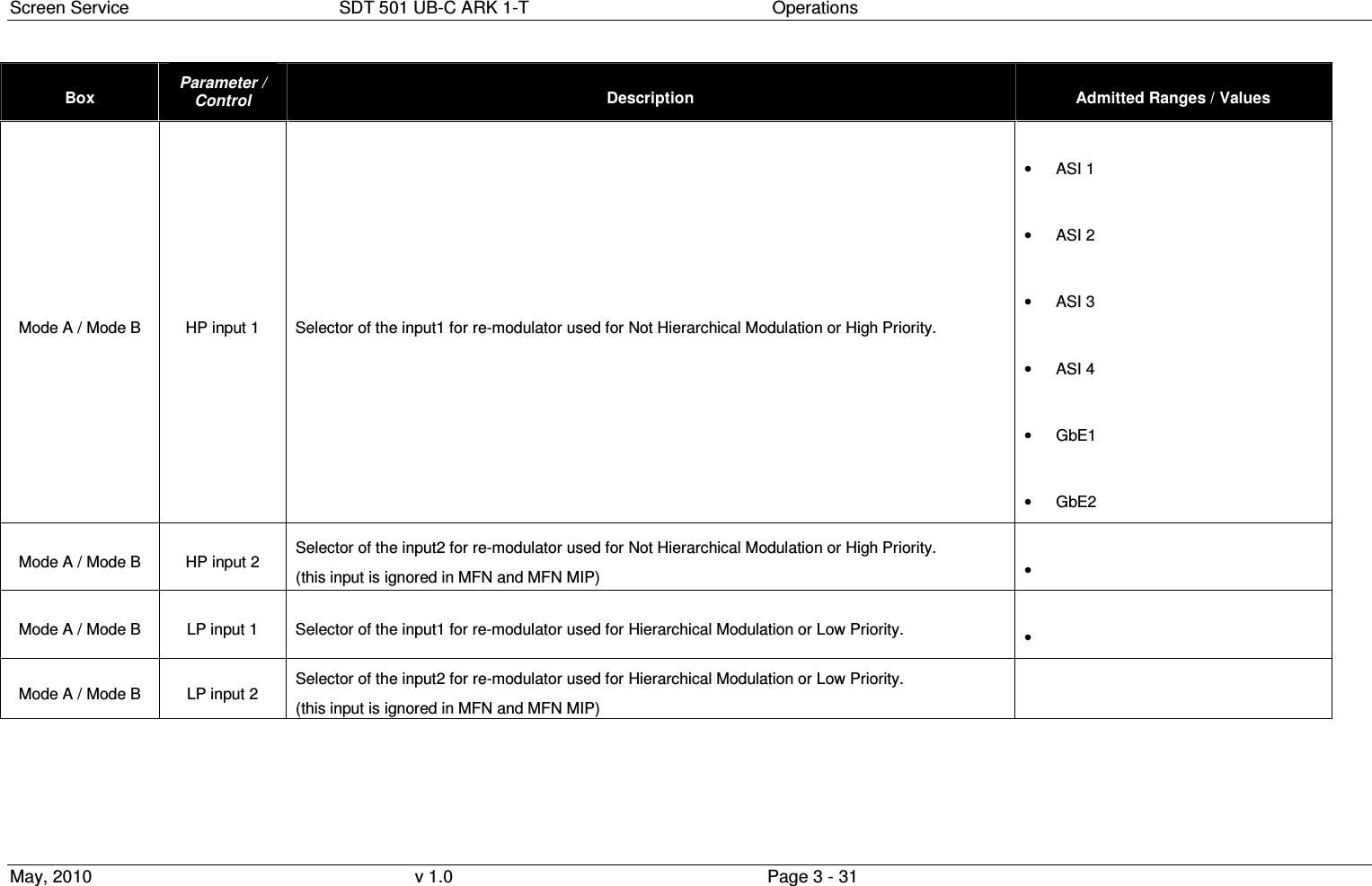
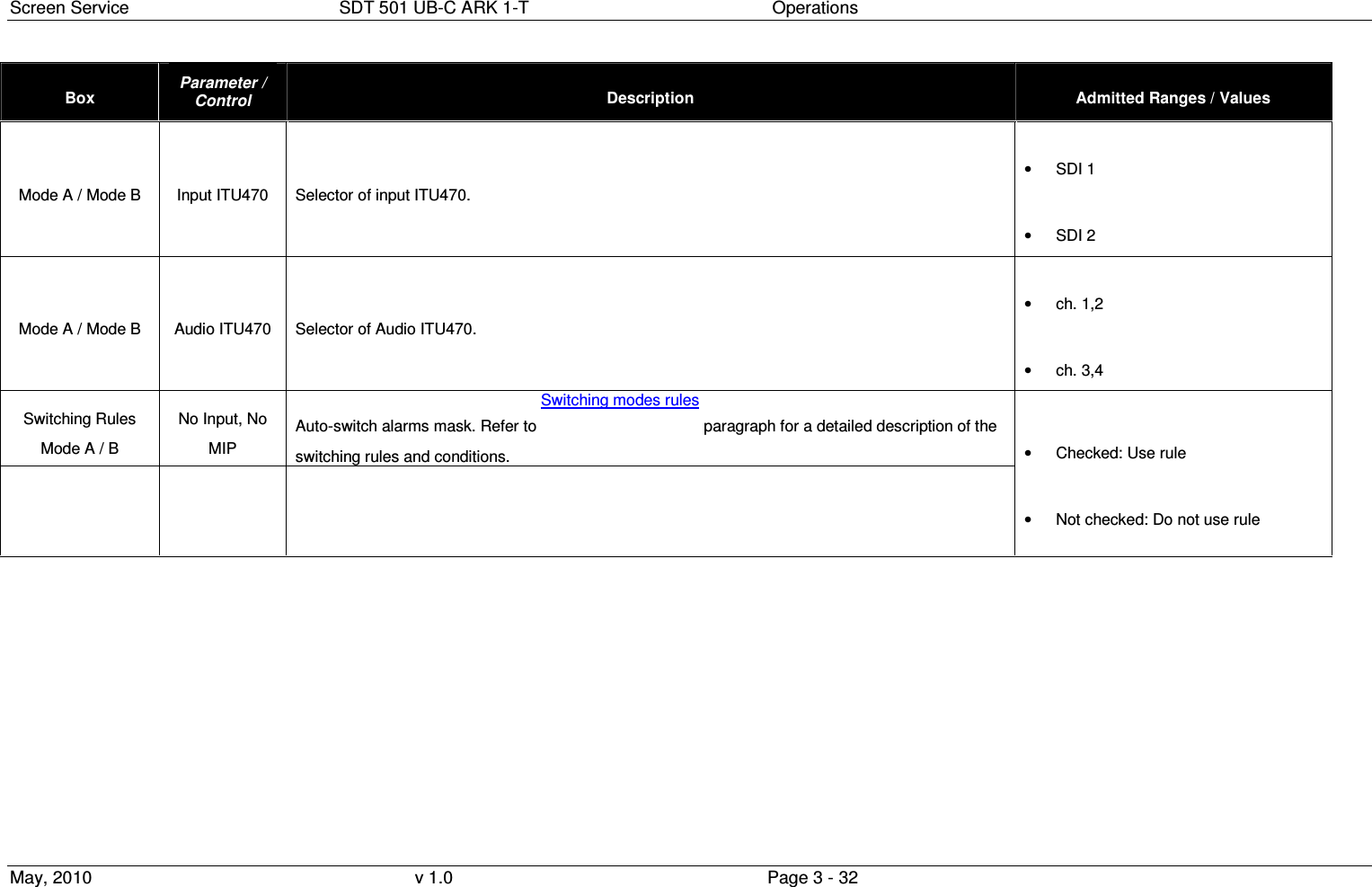
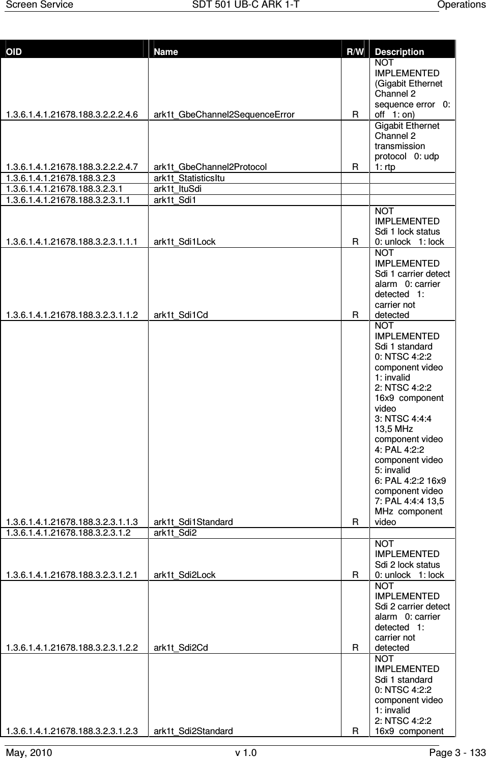
![Screen Service SDT 501 UB-C ARK 1-T Operations May, 2010 v 1.0 Page 3 - 30 Box Parameter / Control Description Admitted Ranges / Values System Mode & Auto-switching Timeout setting Time to wait for switching. Refer to Switching modes rules paragraph for a detailed description of the switching rules. Note: It is highly recommended to set a timeout value different from zero in order to allow the input signal locking. • Min: 0 s • Max: 255 s System Mode & Auto-switching Autoswitch Timeout When Auto Switch Mode is enabled shows the time to wait for switching. If the used input regains lock before the countdown reaches 0 the switch is blocked and device keeps the same mode. • Countdown from 255 to 0 System Mode & Auto-switching Input Alarm Delay [s] Time to wait for No Input alarm rising (refer to Alarms paragraph). Note 1: It is highly recommended to set an Input Alarm Delay value different from zero in order to allow the input signal locking. Note 2: It is highly recommended to set an Input Alarm Delay value not too low (greater than or equal to 1 second) in order to allow the input seamless switching. • Min: 0.1 s • Max: 25.5 s System Mode & Auto-switching Switching Time Time and date of modes switching when Time Switch mode is enabled. Mode A / Mode B Mode A / B Selector of working mode. Only Digital/Analog re-transmitter mode is used by this device. • Tx DVBT • Tx Analog (B,G / PAL)](https://usermanual.wiki/Screen-Service-Broadcasting-Technologies/SDT501UBCARK1T.User-Manual-Part-Three/User-Guide-1390839-Page-30.png)
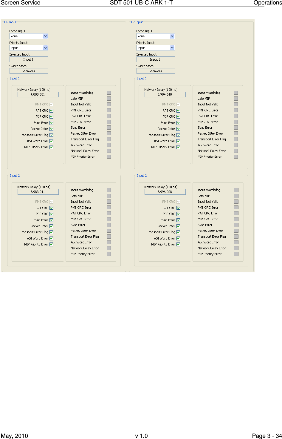
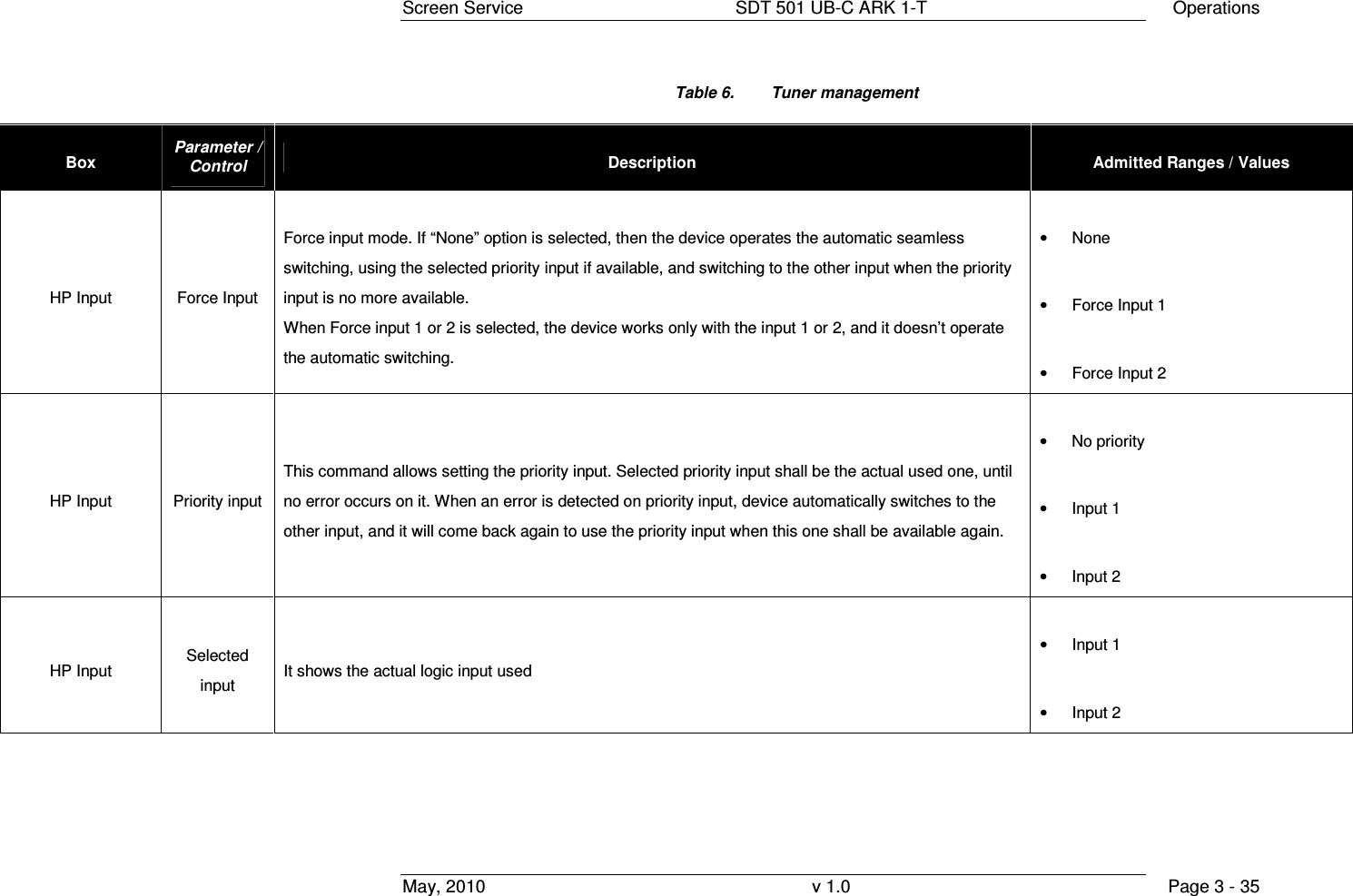
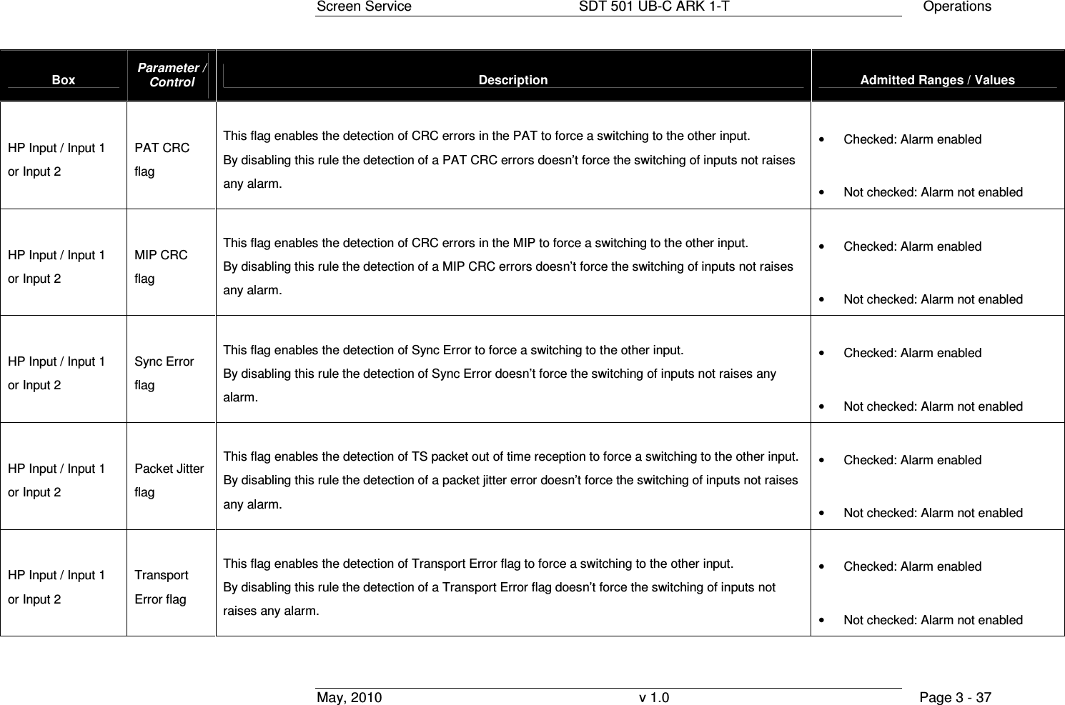
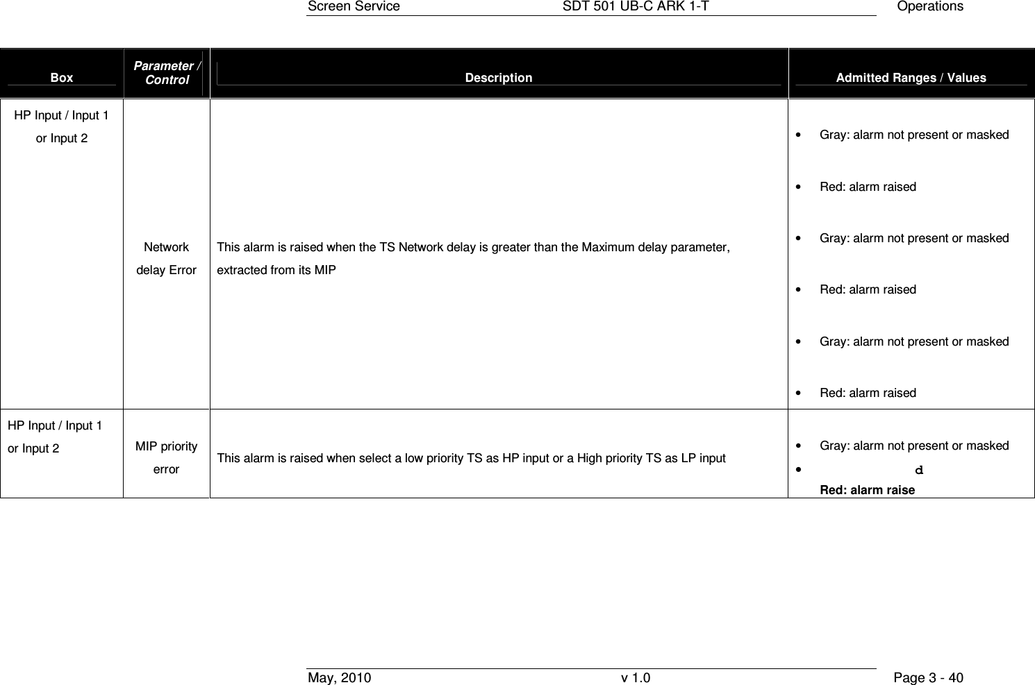
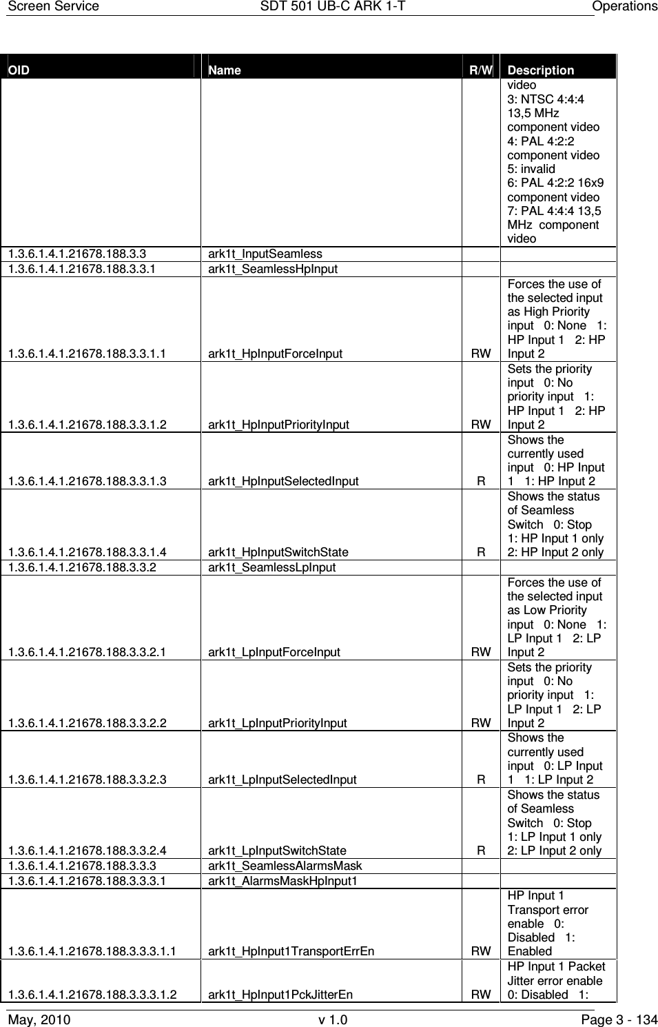
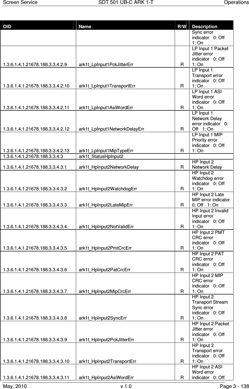
![Screen Service SDT 501 UB-C ARK 1-T Operations May, 2010 v 1.0 Page 3 - 36 Box Parameter / Control Description Admitted Ranges / Values HP Input Switch State This monitor shows the current device switch state. When both the two inputs are available, the input seamless switching is possible; else, if only one input is available, then the switching is no more available. If some error occurs on both inputs, device can’t switch and it can’t use any input. • Stop • Input 1 only • Input 2 only • Seamless • Wait HP Input / Input 1 or Input 2 Network Delay [100 ns] This monitor shows the Network Delay, measured analyzing MIP contained in the input. This delay is expressed in units of 100 ns. • Min: 0 • Max: 9999999 HP Input / Input 1 or Input 2 PMT CRC flag This check isn’t implemented in the actual version. • Checked: Alarm enabled • Not checked: Alarm not enabled](https://usermanual.wiki/Screen-Service-Broadcasting-Technologies/SDT501UBCARK1T.User-Manual-Part-Three/User-Guide-1390839-Page-36.png)
![Screen Service SDT 501 UB-C ARK 1-T Operations May, 2010 v 1.0 Page 3 - 43 Box Parameter/Control Description Admitted Ranges / Values MIP Status MIP HP/LP Status Show the status of the MIP Note: the Network delay Error is ? when the TS input (HP or LP) network delay is greater than the MAX delay written in is MIP • No MIP • MIP OK • Wrong MIP priority • CRC Error • Network delay error MIP Detection MIP Alarm Delay [s] Time to wait for No MIP alarm rising expressed in seconds (refer to Alarms paragraph). Note: It is highly recommended to set a MIP Alarm Delay value different from zero as to allow the MIP detection. • Min: 1 s • Max: 25.5 s Test Force Null Packets Null data packets transmission enabling check box. • Checked: Enabled • Not checked: Disabled](https://usermanual.wiki/Screen-Service-Broadcasting-Technologies/SDT501UBCARK1T.User-Manual-Part-Three/User-Guide-1390839-Page-43.png)
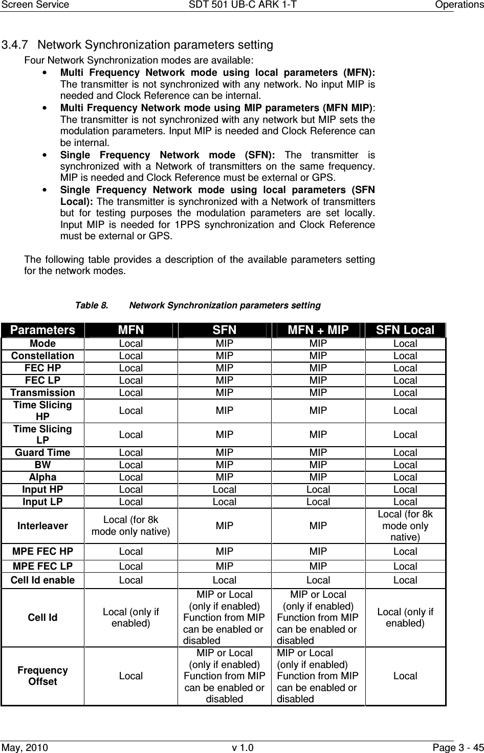
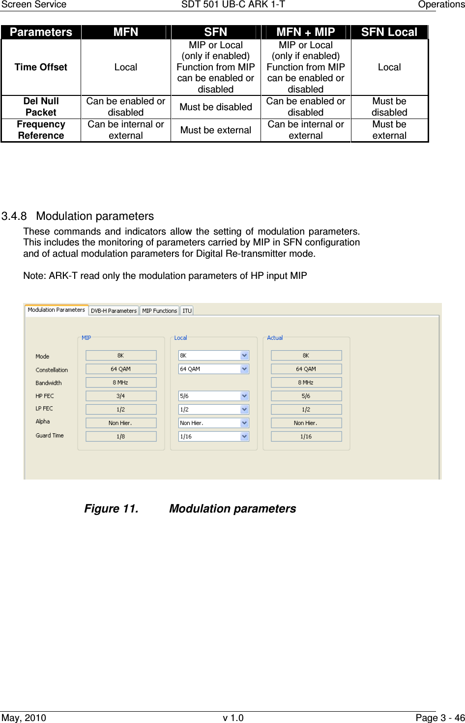
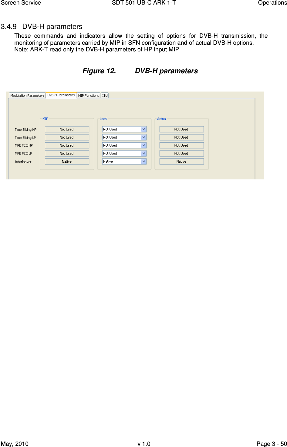
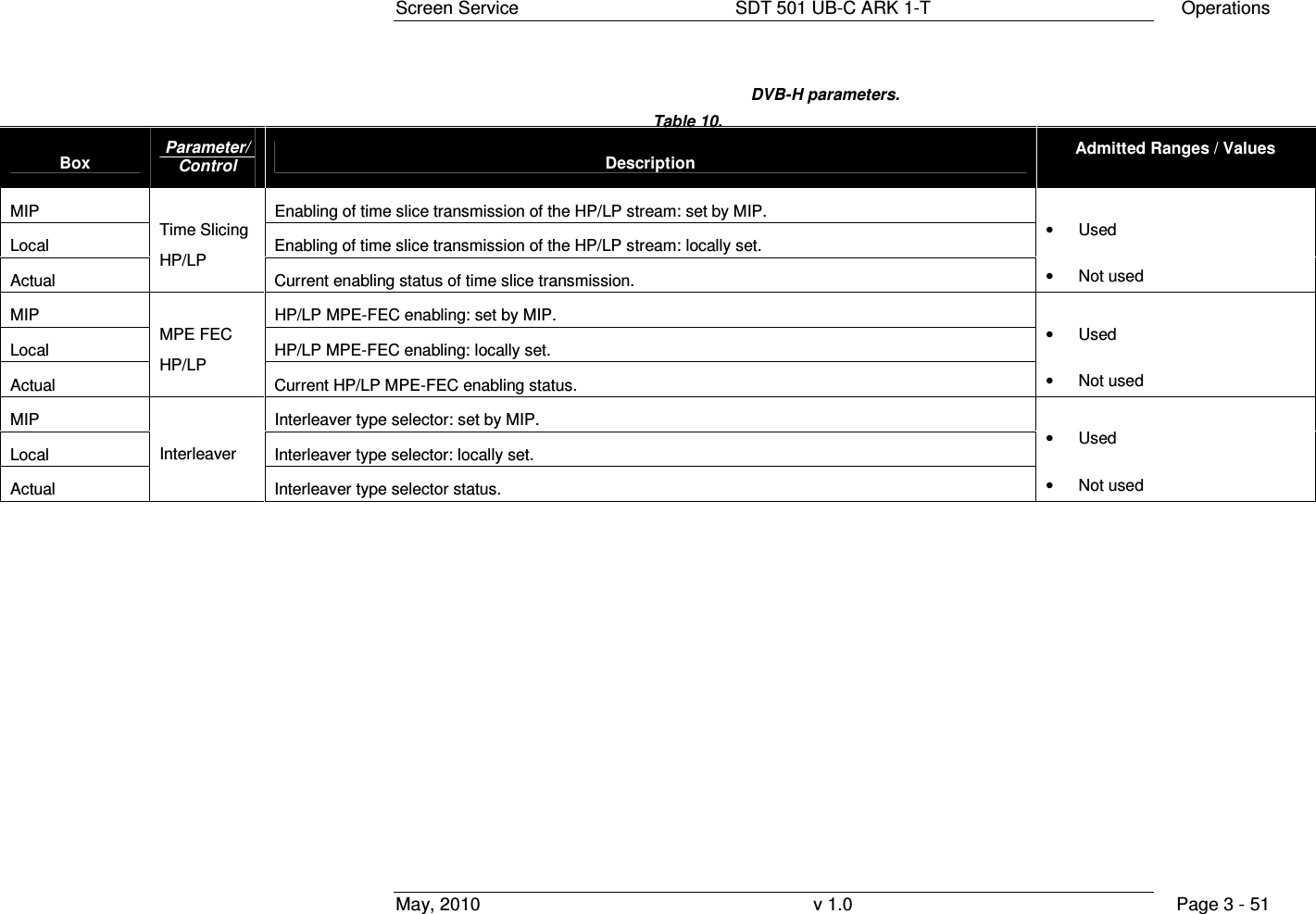
![Screen Service SDT 501 UB-C ARK 1-T Operations May, 2010 v 1.0 Page 3 - 53 Box Parameter / Control Description Admitted Ranges / Values MIP MIP cell ID function enabling Local Cell Id enable General Cell Id enabling. Must be enabled to insert Cell Id into output TPS. • Checked: Enabled • Not checked: Disabled MIP MIP cell ID monitoring. Local Local Cell ID setting. • Min: 0 • Max: 65,535 Actual Cell ID Used Cell ID monitoring. MIP Max Delay [100ns] MIP max delay function monitoring Local User Delay User delay setting. This value is added to the MIP max delay to calculate the Used delay • Min: - 8388608 • Max: 8388607 Actual Delay [100ns] Used delay monitoring. In SFN this value is calculated adding the MIP max delay, the Local user delay, the MIP Time offset, the Local time offset and the Device delay In MFN this value is calculated adding the Local user delay and the Device delay Note: this value must be greater than the HP and LP network delay • Min: 0 • Max: 9,999,999](https://usermanual.wiki/Screen-Service-Broadcasting-Technologies/SDT501UBCARK1T.User-Manual-Part-Three/User-Guide-1390839-Page-53.png)
![Screen Service SDT 501 UB-C ARK 1-T Operations May, 2010 v 1.0 Page 3 - 54 Box Parameter / Control Description Admitted Ranges / Values MIP MIP frequency offset function enabling and monitoring • Checked: Enabled • Not checked: Disabled Local User frequency offset setting. • Min: –500,000 Hz • Max: 500,000 Hz Actual Freq. Offset [Hz] Used frequency offset monitoring. MIP MIP time offset function enabling and monitoring In SFN This value is added to the MIP max delay to calculate the Used delay • Checked: Enabled • Not checked: Disabled Local User time offset setting. In SFN This value is added to the MIP max delay to calculate the Used delay • Min: –32,768 • Max: 32,767 Actual Time Offset [100ns] Used time offset monitoring.](https://usermanual.wiki/Screen-Service-Broadcasting-Technologies/SDT501UBCARK1T.User-Manual-Part-Three/User-Guide-1390839-Page-54.png)
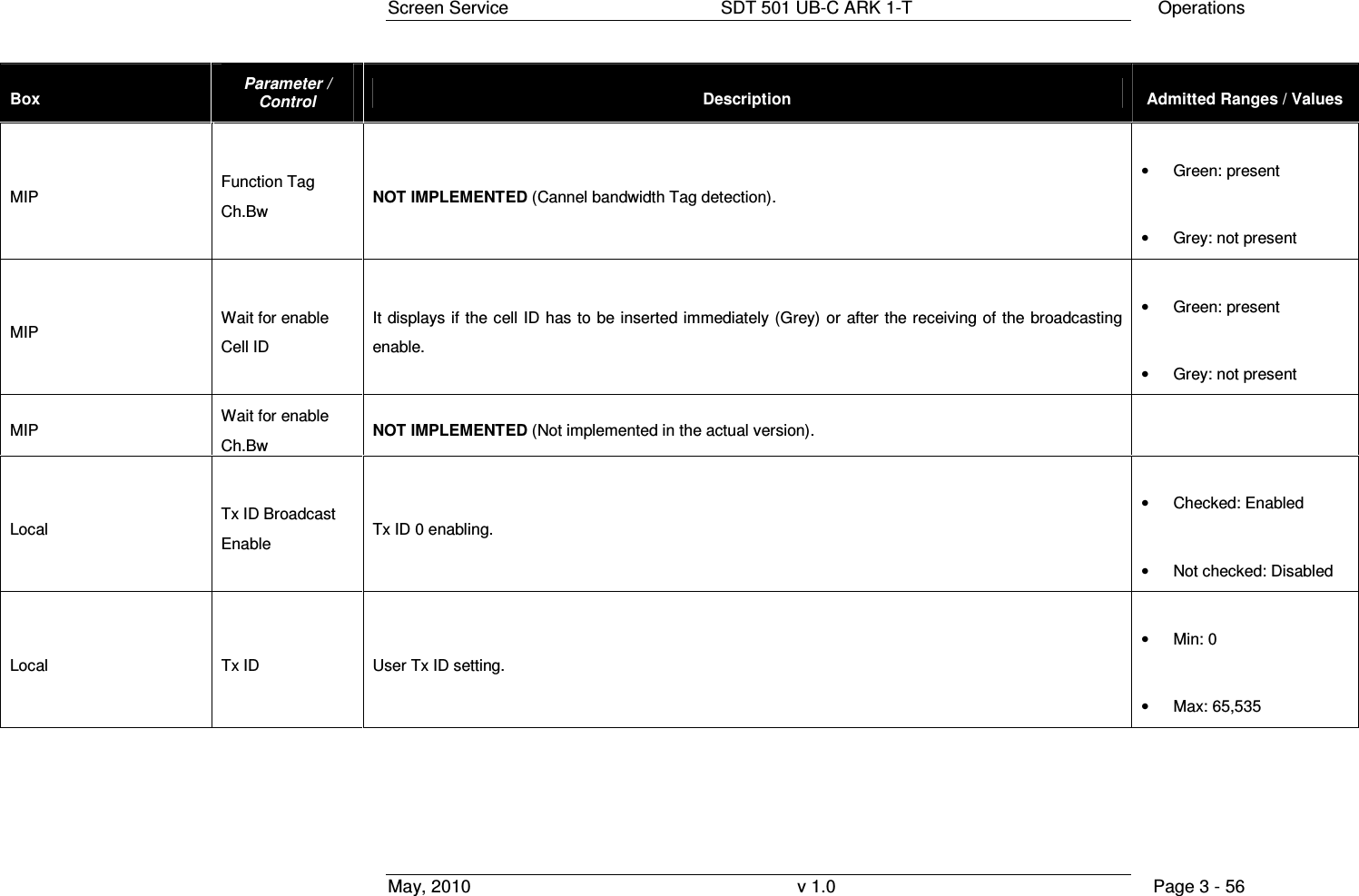
![Screen Service SDT 501 UB-C ARK 1-T Operations May, 2010 v 1.0 Page 3 - 55 Box Parameter / Control Description Admitted Ranges / Values MIP Tx Power [0.1dB] NOT IMPLEMENTED (MIP Tx power function enabling and monitoring). • Checked: Enabled • Not checked: Disabled MIP Func.Bw NOT IMPLEMENTED (Function Bw enabling and monitoring). • Checked: Enabled • Not checked: Disabled MIP Function Cell ID enabled MIP Cell ID function enabling status. • Green: enabled • Grey: disabled MIP Function Tag Cell ID. Cell ID Tag detection. • Green: present • Grey: not present MIP Function Ch.Bw enabled NOT IMPLEMENTED (MIP channel bandwidth function enabling status). • Green: enabled • Grey: disabled](https://usermanual.wiki/Screen-Service-Broadcasting-Technologies/SDT501UBCARK1T.User-Manual-Part-Three/User-Guide-1390839-Page-55.png)
![Screen Service SDT 501 UB-C ARK 1-T Operations May, 2010 v 1.0 Page 3 - 57 Box Parameter / Control Description Admitted Ranges / Values Local Standard User transmission standard setting. • DVB-T o Checked: Enabled o Not checked: Disabled • DVB-H o Checked: Enabled o Not checked: Disabled Actual Center Freq. [Hz] Used center frequency indicator. Actual HP Network Delay [100ns] Used HP input network delay indicator. Actual LP Network Delay [100ns] Used LP input network delay indicator.](https://usermanual.wiki/Screen-Service-Broadcasting-Technologies/SDT501UBCARK1T.User-Manual-Part-Three/User-Guide-1390839-Page-57.png)
![Screen Service SDT 501 UB-C ARK 1-T Operations May, 2010 v 1.0 Page 3 - 58 Box Parameter / Control Description Admitted Ranges / Values Actual Device Delay [100ns] Default device delay monitoring. This value is added to the MIP max delay to calculate the Used delay • Min: - 8388608 • Max: 8388607 Table 11. MIP functions](https://usermanual.wiki/Screen-Service-Broadcasting-Technologies/SDT501UBCARK1T.User-Manual-Part-Three/User-Guide-1390839-Page-58.png)
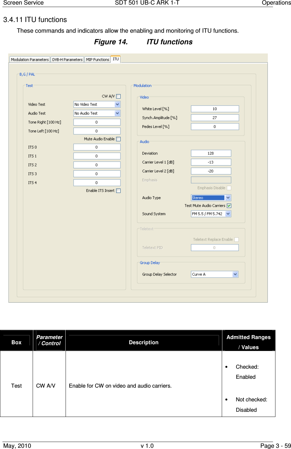
![Screen Service SDT 501 UB-C ARK 1-T Operations May, 2010 v 1.0 Page 3 - 60 Box Parameter / Control Description Admitted Ranges / Values Test Video Test Video test color bars enable. • Bars • No Video Test Test Audio Test Audio test tones enable. • No Video Test • Audio Tone Test Tone Right [100 Hz] Right tone frequency setting. • Min: 0 • Max: 127 Test Tone Left [100 Hz] Left tone frequency setting. • Min: 0 • Max: 127 Test Mute Audio Enable Audio mute enable • Checked: Enabled • Not checked: Disabled Test ITS 0 Position of fixed line number 0 in output video. • Min: 7 • Max: 622 Test ITS 1 Position of fixed line number 1 in output video. • Min: 7 • Max: 622 Test ITS 2 Position of fixed line number 2 in output video. • Min: 7 • Max: 622](https://usermanual.wiki/Screen-Service-Broadcasting-Technologies/SDT501UBCARK1T.User-Manual-Part-Three/User-Guide-1390839-Page-60.png)
![Screen Service SDT 501 UB-C ARK 1-T Operations May, 2010 v 1.0 Page 3 - 61 Box Parameter / Control Description Admitted Ranges / Values Test ITS 3 Position of fixed line number 3 in output video. • Min: 7 • Max: 622 Test ITS 4 Position of fixed line number 4 in output video. • Min: 7 • Max: 622 Test Enable ITS Insert Enable fixed lines insertion in output video. • Checked: Enabled • Not checked: Disabled Modulation / Video White Level [%] Video white level setting. The level value is in percentage upon the synch level. The synch level is taken as 100% reference. • MIN: 10 • MAX: 22 • Step: 0,05 Modulation / Video Synch. Amplitude [%] Video synch amplitude setting. The level value is in percentage upon the synch level. The synch level is taken as 100% reference. • MIN: 22 • MAX: 27,5 • Step: 0,05 Modulation / Video Pedes Level [%] Video pedes level setting. The level value is in percentage upon the synch level. The synch level is taken as 100% reference. • MIN: 0 • MAX: 7 • Step: 0,05](https://usermanual.wiki/Screen-Service-Broadcasting-Technologies/SDT501UBCARK1T.User-Manual-Part-Three/User-Guide-1390839-Page-61.png)
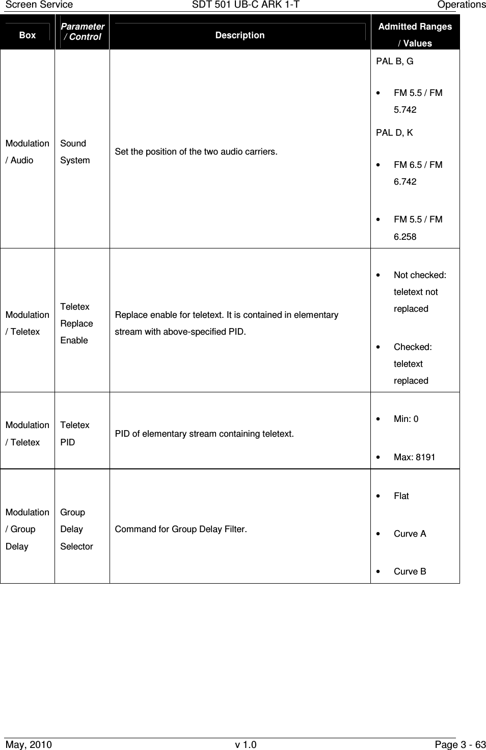
![Screen Service SDT 501 UB-C ARK 1-T Operations May, 2010 v 1.0 Page 3 - 62 Box Parameter / Control Description Admitted Ranges / Values Modulation / Audio Deviation Audio deviation. • Min: 0 • Max: 255 Modulation / Audio Carrier Level 1 [dB] Audio 1 carrier level setting. • MIN: –7 • MAX: –22 • Step: 0,1 Modulation / Audio Carrier Level 2 [dB] Audio 2 carrier level setting. Not used for NTSC • MIN: –7 • MAX: -–22 • Step: 0,1 Modulation / Audio Emphasis Audio emphasis value monitor. Modulation / Audio Emphasis disable Disable Audio emphasis Modulation / Audio Audio Type Audio type selector. Only the mono single carrier audio type is used for NTSC. • Mono Dual Carrier • Dual Sound • Stereo • Mono Single Carrier Modulation / Audio Test Mute Audio Carriers Remove the audio carrier. • Checked: Enabled • Not checked: Disabled](https://usermanual.wiki/Screen-Service-Broadcasting-Technologies/SDT501UBCARK1T.User-Manual-Part-Three/User-Guide-1390839-Page-62.png)
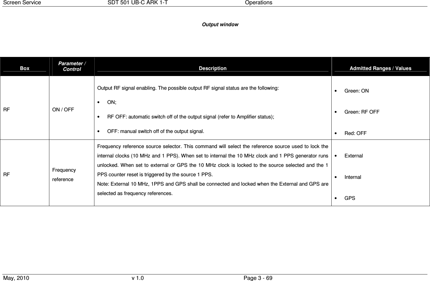
![Screen Service SDT 501 UB-C ARK 1-T Operations May, 2010 v 1.0 Page 3 - 70 Box Parameter / Control Description Admitted Ranges / Values RF Internal Freq. Ref. Tune Internal frequency reference fine tuning setting. Allows the fine tuning of VCO, internal clock oscillator, with 60 Hz steps. • Min: 0 • Max: 255 AGC AGC ON AGC status. • Green: ON • Grey: OFF AGC Mode Current AGC mode indicator. It is always digital. • Analog/Digital: o Green: ON o Grey: OFF Frequency Out [Hz] Frequency Out [Hz] Shows the output center frequency expressed in Hz.](https://usermanual.wiki/Screen-Service-Broadcasting-Technologies/SDT501UBCARK1T.User-Manual-Part-Three/User-Guide-1390839-Page-70.png)
![Screen Service SDT 501 UB-C ARK 1-T Operations May, 2010 v 1.0 Page 3 - 72 Box Parameter / Control Description Admitted Ranges / Values Status PS1 28V / 42V First PSU voltage indicator (values are expressed in V). It depends on the hardware type of the device: • 28V for SDTx 20 and SDTx 50; • 42V for SDTx 201 and SDTx 501; Status PS1 Current 28V / 42V [A] First PSU current indicator (values are expressed in A) It depends on the hardware type of the device: • 28V for SDTx 20 and SDTx 50; • 42V for SDTx 201 and SDTx 501; Status PS1 24V First PSU 24V indicator (values are expressed in V). Only in SDTX 201 and SDTX 501 version. Status PS2 42V Second PSU voltage indicator (values are expressed in V). Only in SDTX 501 version. Status PS2 Current 42V [A] Second PSU current indicator (values are expressed in A) Only in SDTX 501 version. Status PS2 24V Second PSU 24V indicator (values are expressed in V). Only in SDTX 501 version. Status Case Temperature Case temperature indicator (values are expressed in °C). Status Case Temperature 2 2nd Case temperature indicator (values are expressed in °C). Only in SDTX 200 version.](https://usermanual.wiki/Screen-Service-Broadcasting-Technologies/SDT501UBCARK1T.User-Manual-Part-Three/User-Guide-1390839-Page-72.png)
![Screen Service SDT 501 UB-C ARK 1-T Operations May, 2010 v 1.0 Page 3 - 73 Box Parameter / Control Description Admitted Ranges / Values Status PSU Temperature PSU temperature indicator (values are expressed in °C). Status Fan 1 Fan 1 speed indicator (values are expressed in rpm). Used in SDTX20, SDTX50 and SDTX201 Status Fan 2 Fan 2 speed indicator (values are expressed in rpm). Used in SDTX20, SDTX50 SDTX201, and SDTX501 Status Fan 3 Fan 3 speed indicator (values are expressed in rpm). Used in SDTX201, and SDTX501 Status Fan 4 Fan 4 speed indicator (values are expressed in rpm). Used in SDTX201, and SDTX501 Status FWD Power [dBm] Output forward power indicator (values are expressed in dBm). Status Reflex Power [dBm] Output reflex power indicator (values are expressed in dBm).](https://usermanual.wiki/Screen-Service-Broadcasting-Technologies/SDT501UBCARK1T.User-Manual-Part-Three/User-Guide-1390839-Page-73.png)
![Screen Service SDT 501 UB-C ARK 1-T Operations May, 2010 v 1.0 Page 3 - 76 Box Parameter / Control Description Admitted Ranges / Values Opto&Relay Opto 3 Stand-by enabling Opto status indicators: .( in version SDTX 20/50/201); • Closed (0): stand-by off • Opened (1): stand-by on Interlock Opto status indicators.(only in SDTX 501 version); • Closed (0): Interlock off • Opened (1): Interlock on • Green: Closed (0) • Grey: Opened (1) Mode A / Mode B Channel Output channel. Channel ranges are device’s definition dependant. Mode A / Mode B Power [dBm] Output power (expressed in dBm). Mode A / Mode B Power [W] Output power (expressed in W). Output power ranges are device’s definition dependant. Refer to Appendix C](https://usermanual.wiki/Screen-Service-Broadcasting-Technologies/SDT501UBCARK1T.User-Manual-Part-Three/User-Guide-1390839-Page-76.png)
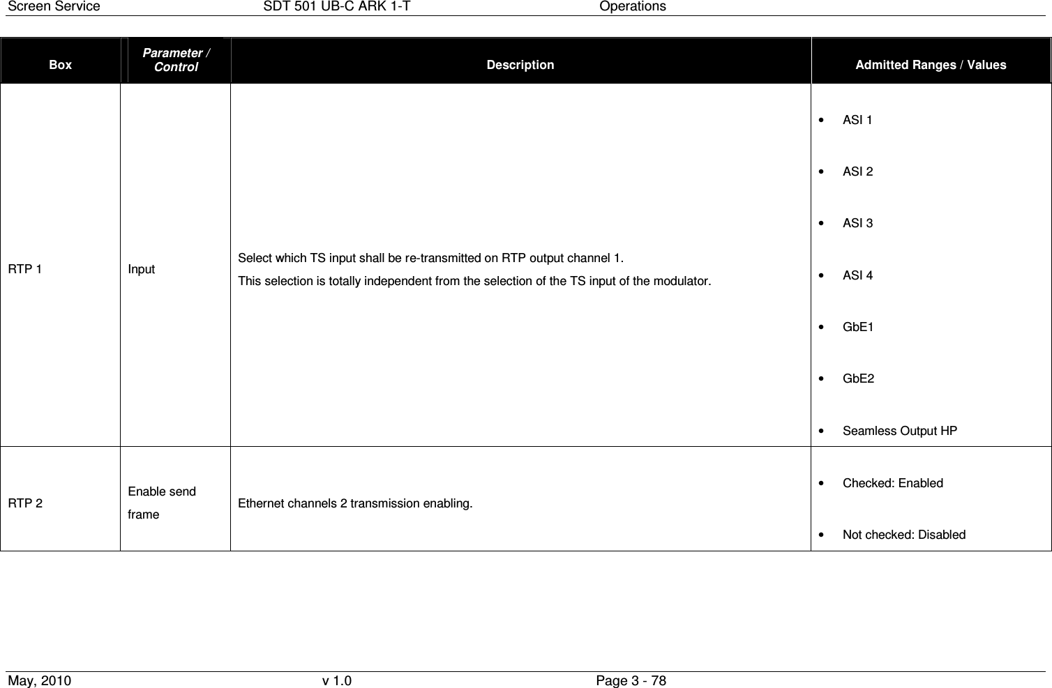
![Screen Service SDT 501 UB-C ARK 1-T Operations May, 2010 v 1.0 Page 3 - 77 Box Parameter / Control Description Admitted Ranges / Values Mode A / Mode B Offset [Hz] Output frequency offset (expressed in Hz). • Min: -4 MHz • Max: 4 MHz FWD Power Thresholds Warning [dB] Forward power warning threshold expressed in dBm. FWD Power Thresholds Alarm [dB] Forward power alarm threshold expressed in dBm. • Min: -16 dBm • Max: 0 dBm Temperature Thresholds Warning Case temperature warning threshold expressed in °C. Temperature Thresholds Alarm Case temperature alarm threshold expressed in °C. • Min: 0 °C • Max: 100 °C RTP 1 Enable send frame Ethernet channels 1 transmission enabling. • Checked: Enabled • Not checked: Disabled](https://usermanual.wiki/Screen-Service-Broadcasting-Technologies/SDT501UBCARK1T.User-Manual-Part-Three/User-Guide-1390839-Page-77.png)

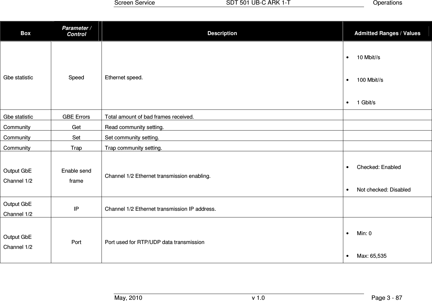
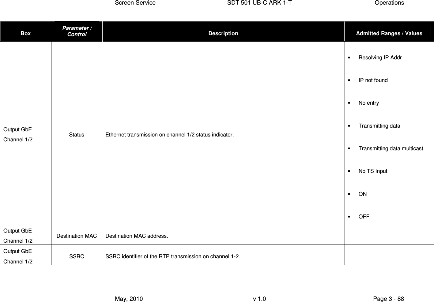
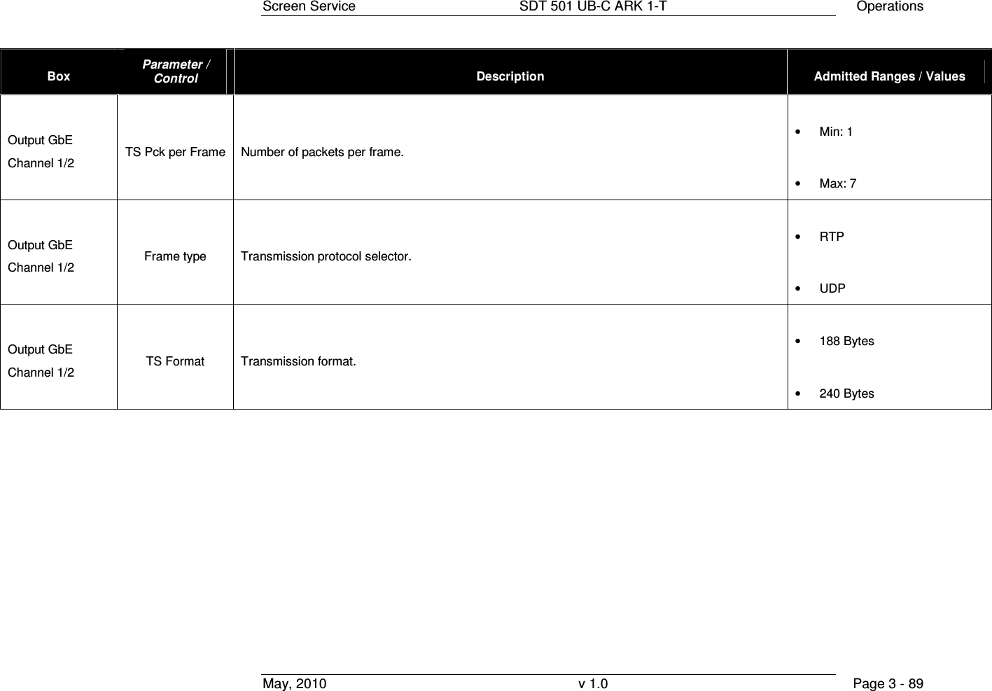
![Screen Service SDT 501 UB-C ARK 1-T Operations May, 2010 v 1.0 Page 3 - 85 Box Parameter / Control Description Admitted Ranges / Values Input GbE Channel 1/2 Protocol Ethernet input packets protocol. • UDP/RTP: o Green: Detected o Grey: Not detected Input GbE Channel 1/2 Bit-rate [bit/s] Bit-rate of TS from Ethernet input. Input GbE Channel 1/2 Filtered bit-rate [bit/s] Bit-rate actually used by the modulator. • Zero when the input is not selected • Equal to the total bit-rate, when Delete Null Packets disabled • Less than total bit-rate, when Delete Null Packets enabled Input GbE Channel 1/2 Format Received transmission format. • 188 Bytes • 240 Bytes](https://usermanual.wiki/Screen-Service-Broadcasting-Technologies/SDT501UBCARK1T.User-Manual-Part-Three/User-Guide-1390839-Page-85.png)
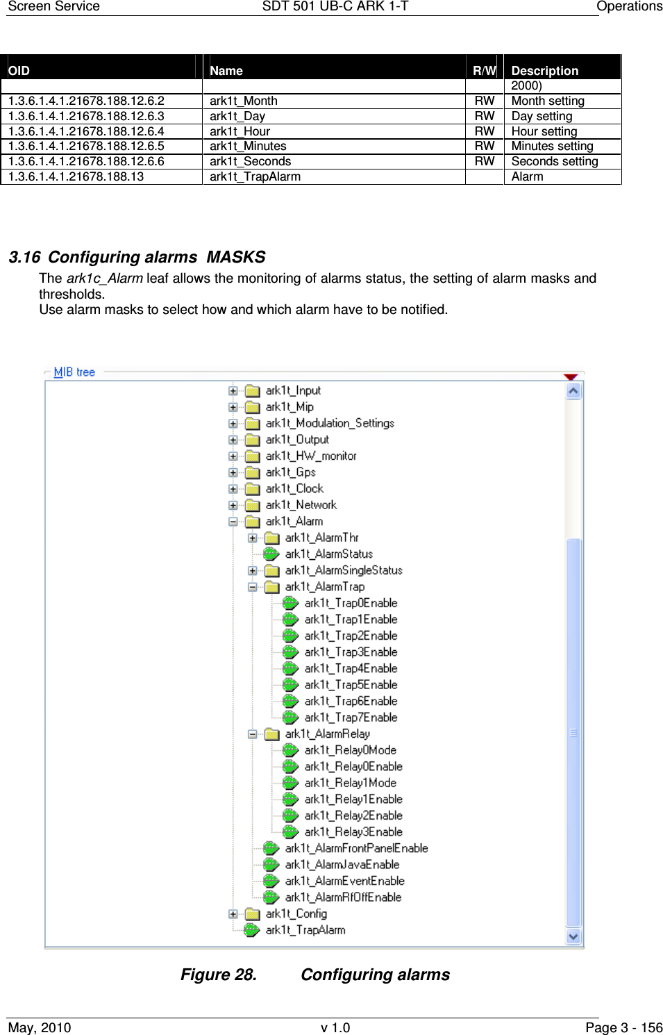
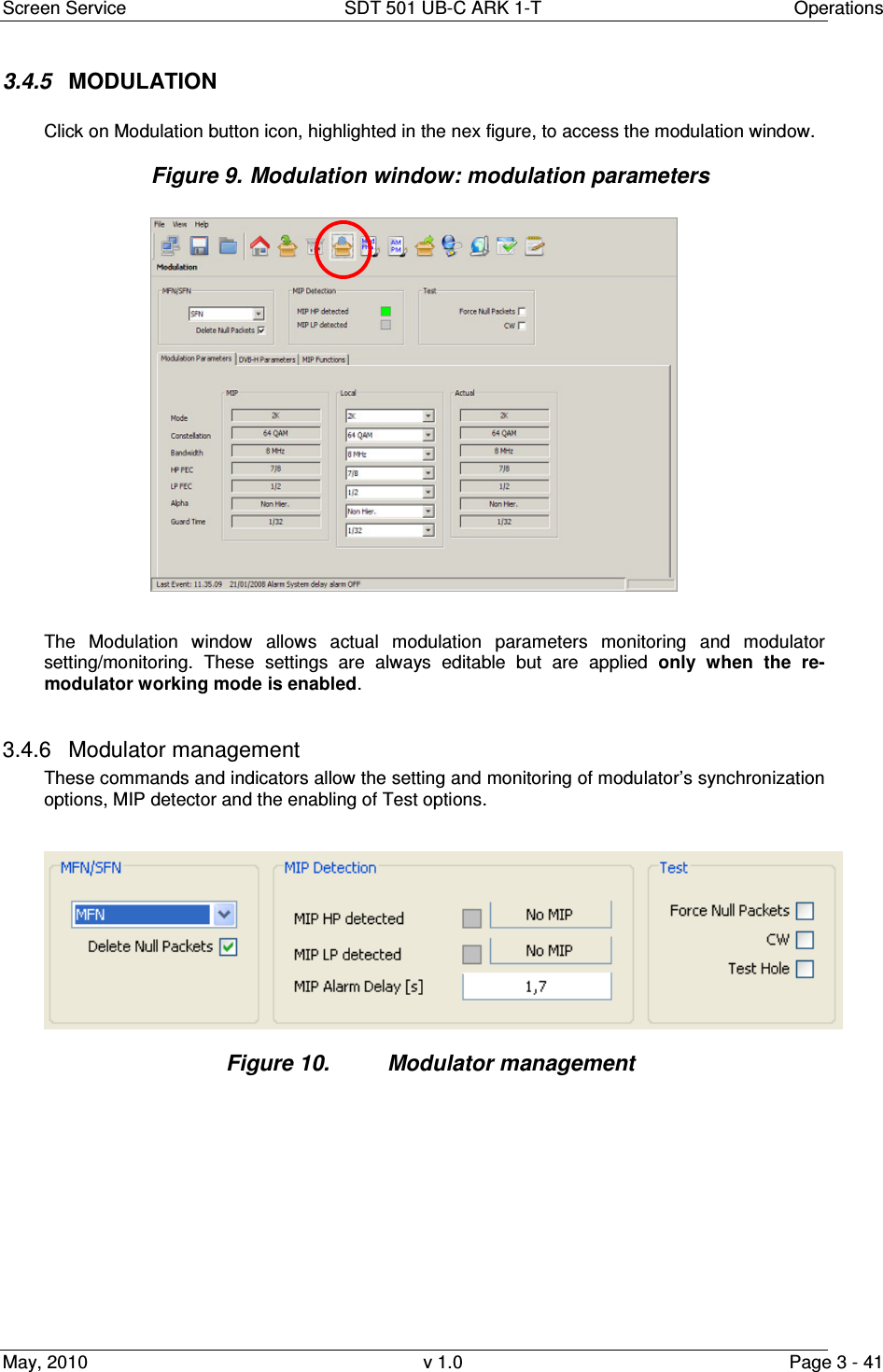
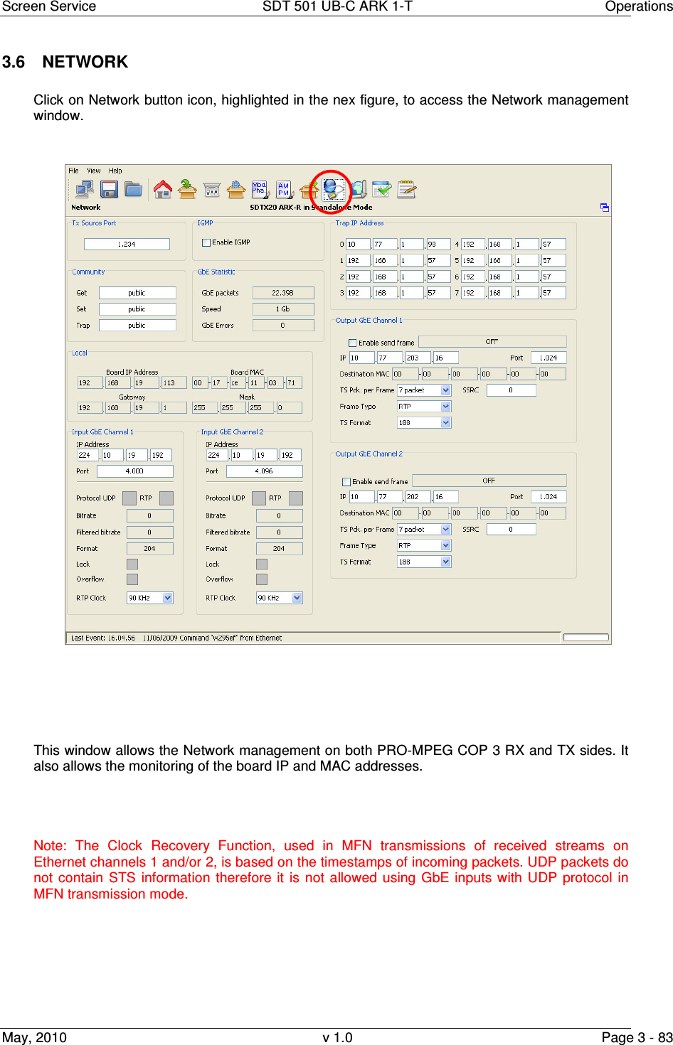
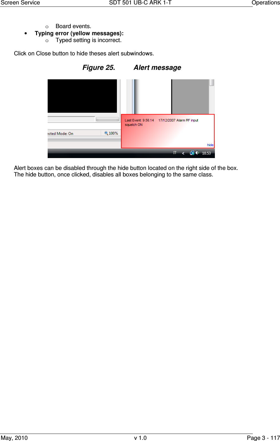
![Screen Service SDT 501 UB-C ARK 1-T Operations May, 2010 v 1.0 Page 3 - 116 3.10 Option sub-menu The Option sub-menu allows two controls type: • Time: Time Read Interval [s]; • Alerts: the selection of events to display. 3.10.1 Time Figure 23. Time subwindow This control allows to change the device-to-management PC java update time. The default value is 2 seconds. Click on Close button quit this sub-window. 3.10.2 Alerts Figure 24. Alerts subwindow The Alert subwindow allows the selection of which type of event has to be notified through an Alert box. Alert boxes appear on the right side of the monitor. The selection is performed among the following types of event: • Commands (blue boxes): o Gigabit Ethernet commands; o RS232 commands; o SNMP commands; o LCD Display commands. • Alarms (red boxes); • Events (green messages):](https://usermanual.wiki/Screen-Service-Broadcasting-Technologies/SDT501UBCARK1T.User-Manual-Part-Three/User-Guide-1390839-Page-116.png)
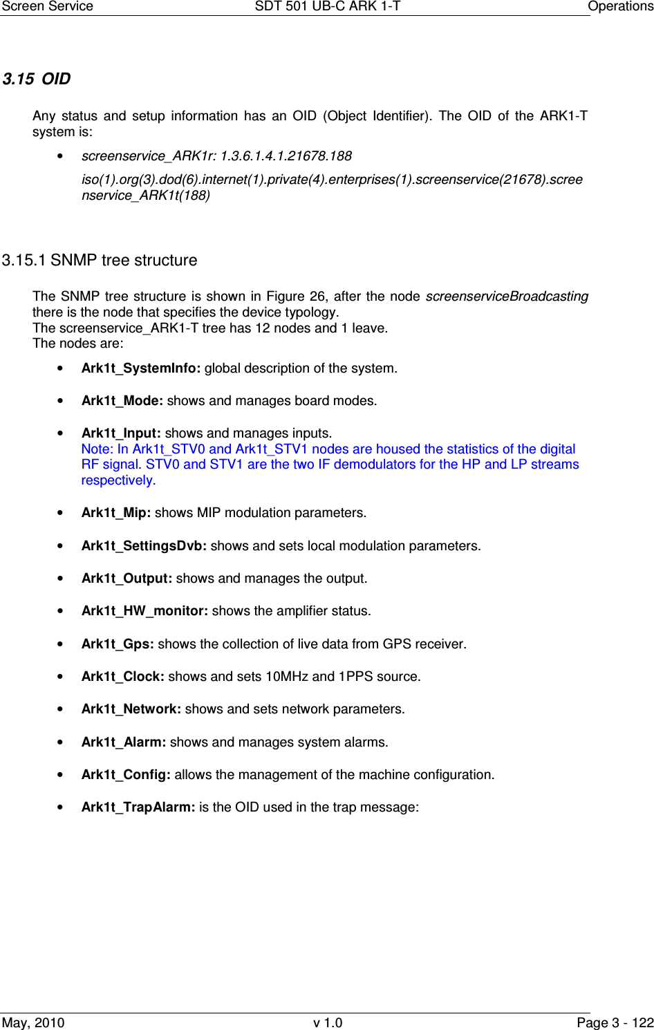
![Screen Service SDT 501 UB-C ARK 1-T Operations May, 2010 v 1.0 Page 3 - 120 3.13 SNMP Protocol Preferences Go to SNMP Protocol Preferences. The following parameters should be set in order to correctly configure the SNMP Manager: • SNMP protocol version: SNMPv1; • Read Community: the same of the one set in the Get field of Java interface, community section; • Set Community: the same of the one set in the Set field of Java interface, community section; • Timeout [s]: user defined; • Retransmits: user defined; • Port number: 161. Next figure illustrates how to configure SNMP Protocol Preferences using MG_SOFT MIB Browser as an example. Figure 3.12-1: SNMP Protocol Preferences Community on the SNMP Protocol Preferences.](https://usermanual.wiki/Screen-Service-Broadcasting-Technologies/SDT501UBCARK1T.User-Manual-Part-Three/User-Guide-1390839-Page-120.png)
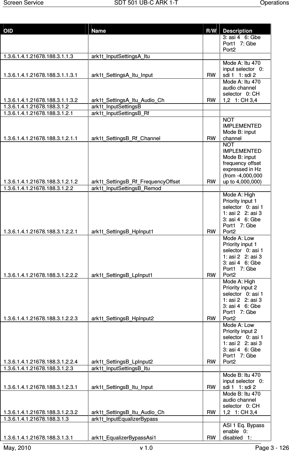
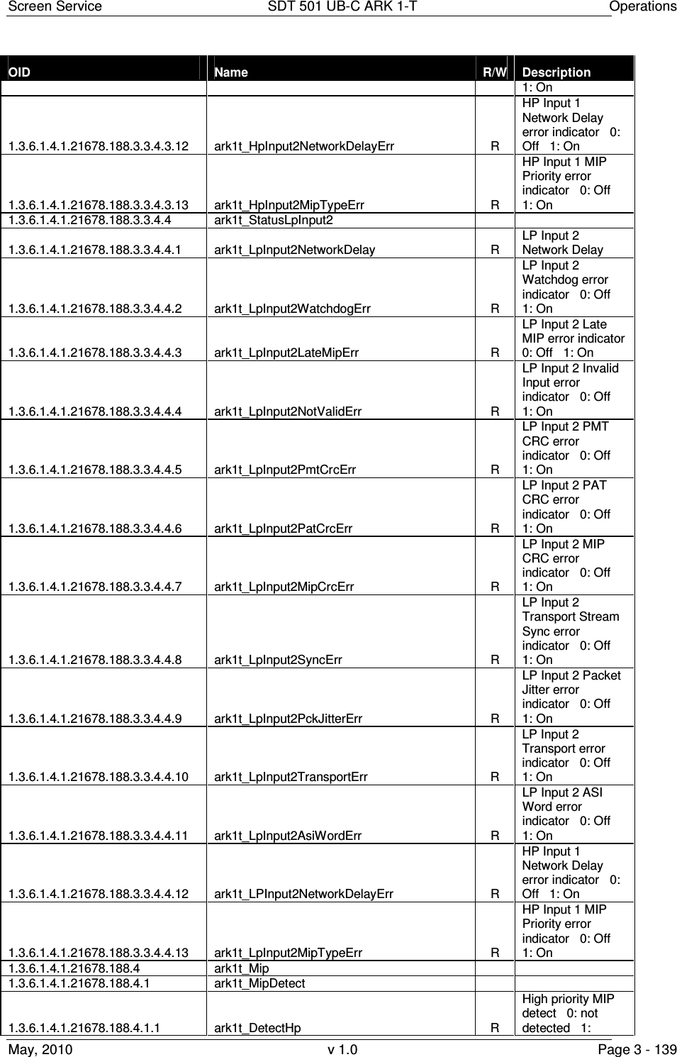
![Screen Service SDT 501 UB-C ARK 1-T Operations May, 2010 v 1.0 Page 3 - 141 OID Name R/W Description depth symbol interleaver selector 0: native 1: in-depth 1.3.6.1.4.1.21678.188.4.5 ark1t_MipAlpha R MIP alpha 0: not hierarchical 1: alpha=1 2: alpha=2 3: alpha=4 1.3.6.1.4.1.21678.188.4.6 ark1t_MipGuardTime R MIP guard interval 0:1/32 1:1/16 2:1/8 3:1/4 1.3.6.1.4.1.21678.188.4.7 ark1t_MipFft R MIP transmission mode 0:2K 1:8K 2:4K 1.3.6.1.4.1.21678.188.4.8 ark1t_MipBandwidth R MIP bandwidth 0: 7MHz 1: 8MHz 2: 6MHz 3: 5MHz 1.3.6.1.4.1.21678.188.4.9 ark1t_MipFec 1.3.6.1.4.1.21678.188.4.9.1 ark1t_MipFecHp R MIP High priority FEC 0: 1/2 1: 2/3 2: 3/4 3: 5/6 4: 7/8 1.3.6.1.4.1.21678.188.4.9.2 ark1t_MipFecLp R MIP Low priority FEC 0: 1/2 1: 2/3 2: 3/4 3: 5/6 4: 7/8 1.3.6.1.4.1.21678.188.4.10 ark1t_MipTimeSlicing 1.3.6.1.4.1.21678.188.4.10.1 ark1t_MipTimeSlicingHp R MIP High priority time slicing 0: not used 1: used 1.3.6.1.4.1.21678.188.4.10.2 ark1t_MipTimeSlicingLp R MIP Low priority time slicing 0: not used 1: used 1.3.6.1.4.1.21678.188.4.11 ark1t_MipMpeFec 1.3.6.1.4.1.21678.188.4.11.1 ark1t_MipMpeFecHp R High priority MPE-FEC 0: not used 1: used 1.3.6.1.4.1.21678.188.4.11.2 ark1t_MipMpeFecLp R Low priority MPE-FEC 0: not used 1: used 1.3.6.1.4.1.21678.188.4.12 ark1t_MipDelayTx R MIP transmission delay 1.3.6.1.4.1.21678.188.4.13 ark1t_MipMaxDelay R MIP maximum delay [100ns] 1.3.6.1.4.1.21678.188.4.14 ark1t_MipTimeOffset 1.3.6.1.4.1.21678.188.4.14.1 ark1t_TimeOffsetEnable RW MIP time offset enable 0: disabled 1: enabled 1.3.6.1.4.1.21678.188.4.14.2 ark1t_TimeOffsetStatus R MIP time offset [100ns] 1.3.6.1.4.1.21678.188.4.15 ark1t_MipFrequencyOffset 1.3.6.1.4.1.21678.188.4.15.1 ark1t_FrequencyOffsetEnable RW MIP frequency offset enable 0: disabled 1: enabled 1.3.6.1.4.1.21678.188.4.15.2 ark1t_FrequencyOffsetStatus R MIP frequency offset [Hz] 1.3.6.1.4.1.21678.188.4.16 ark1t_MipTxPower 1.3.6.1.4.1.21678.188.4.16.1 ark1t_TxPoweEnable R NOT IMPLEMENTED (MIP transmission power enable 0:](https://usermanual.wiki/Screen-Service-Broadcasting-Technologies/SDT501UBCARK1T.User-Manual-Part-Three/User-Guide-1390839-Page-141.png)
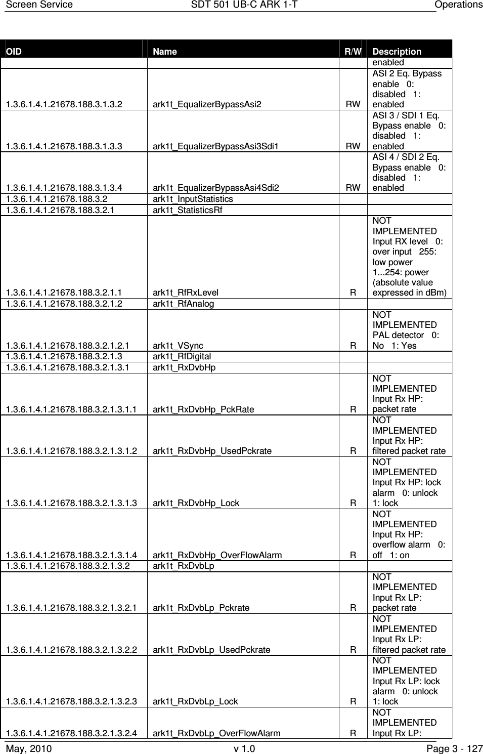
![Screen Service SDT 501 UB-C ARK 1-T Operations May, 2010 v 1.0 Page 3 - 142 OID Name R/W Description disabled 1: enabled) 1.3.6.1.4.1.21678.188.4.16.2 ark1t_TxPowerStatus R MIP transmission power [0.1 dB] 1.3.6.1.4.1.21678.188.4.17 ark1t_MipCellId 1.3.6.1.4.1.21678.188.4.17.1 ark1t_CellIdEnable RW Cell id function enable 0: disabled 1: enabled 1.3.6.1.4.1.21678.188.4.17.2 ark1t_CellIdFunctionEnable R Enable function status 0: not received 1: received 1.3.6.1.4.1.21678.188.4.17.3 ark1t_CellIdFunctionTag R Cell id function tag 0: not detected 1: detected 1.3.6.1.4.1.21678.188.4.17.4 ark1t_CellIdStatus R Cell id function 1.3.6.1.4.1.21678.188.4.17.5 ark1t_CellIdWaitForEnable R Cell id function wait for enable 0: disabled 1: enabled 1.3.6.1.4.1.21678.188.4.18 ark1t_MipFunctionBw 1.3.6.1.4.1.21678.188.4.18.1 ark1t_FunctionBwEnable R NOT IMPLEMENTED (Bandwidth function enable 0: disabled 1: enabled) 1.3.6.1.4.1.21678.188.4.18.2 ark1t_FunctionBwStatus R Bandwidth function 0: 5MHz 1: reserved for future use 1.3.6.1.4.1.21678.188.4.18.3 ark1t_FunctionBwEnableRx R Enable function status 0: not received 1: received 1.3.6.1.4.1.21678.188.4.18.4 ark1t_FunctionChBwTag R Bandwidth function tag 0: not detected 1: detected 1.3.6.1.4.1.21678.188.4.18.5 ark1t_FunctionChBwWaitForEnable R Channel bandwidth function wait for enabled 0: disabled 1: enabled 1.3.6.1.4.1.21678.188.5 ark1t_Modulation_Settings 1.3.6.1.4.1.21678.188.5.1 ark1t_SettingsDvb 1.3.6.1.4.1.21678.188.5.1.1 ark1t_SettingsDvb_CellIdEnable RW Cell Id enable 0: disabled 1: enabled 1.3.6.1.4.1.21678.188.5.1.2 ark1t_SettingsDvb_TxModeSel 1.3.6.1.4.1.21678.188.5.1.2.1 ark1t_TxModeSelDvb_T_H RW Transmitter mode selection 0 : DVB-T 1: DVB-H 1.3.6.1.4.1.21678.188.5.1.2.2 ark1t_TxModeSel_Mfn_Sfn RW Transmitter mode selection 0 : MFN 1: SFN 1.3.6.1.4.1.21678.188.5.1.2.3 ark1t_TxModeSel_Mip RW Transmitter mode selection 0 : Local 1: MIP 1.3.6.1.4.1.21678.188.5.1.3 ark1t_SettingsDvb_Local 1.3.6.1.4.1.21678.188.5.1.3.1 ark1t_LocalFft RW Transmission mode selector 0: 2K 1: 8K 2: 4K](https://usermanual.wiki/Screen-Service-Broadcasting-Technologies/SDT501UBCARK1T.User-Manual-Part-Three/User-Guide-1390839-Page-142.png)
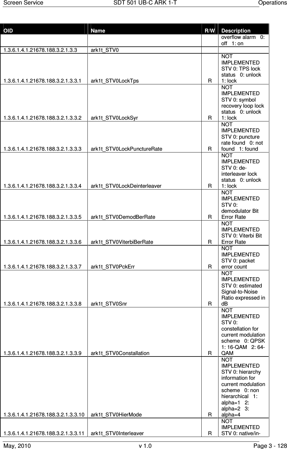
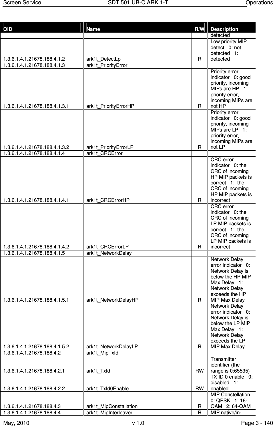
![Screen Service SDT 501 UB-C ARK 1-T Operations May, 2010 v 1.0 Page 3 - 143 OID Name R/W Description 1.3.6.1.4.1.21678.188.5.1.3.2 ark1t_LocalGuardTime RW Guard time selector 0: 1/32 1: 1/16 2: 1/8 3: 1/4 1.3.6.1.4.1.21678.188.5.1.3.3 ark1t_LocalAlpha RW Alpha selector 0: not hierarchical 1: alpha=1 2: alpha=2 3: alpha=4 1.3.6.1.4.1.21678.188.5.1.3.4 ark1t_LocalConstellation RW Constellation selector 0: QPSK 1: 16-QAM 2: 64-QAM 1.3.6.1.4.1.21678.188.5.1.3.5 ark1t_LocalSettingsFec 1.3.6.1.4.1.21678.188.5.1.3.5.1 ark1t_SettingsFecHp RW High priority FEC 0: 1/2 1: 2/3 2: 3/4 3: 5/6 4: 7/8 1.3.6.1.4.1.21678.188.5.1.3.5.2 ark1t_SettingsFecLP RW Low priority FEC 0: 1/2 1: 2/3 2: 3/4 3: 5/6 4: 7/8 1.3.6.1.4.1.21678.188.5.1.3.6 ark1t_LocalCellId RW Local cell id setting (the range is 0:65535) 1.3.6.1.4.1.21678.188.5.1.3.7 ark1t_LocalInterleaver RW Symbol interleaver selector 0: native 1: in-depth 1.3.6.1.4.1.21678.188.5.1.3.8 ark1t_LocalTimeSlicing 1.3.6.1.4.1.21678.188.5.1.3.8.1 ark1t_TimeSlicingHp RW High priority time slicing 0: not used 1: used 1.3.6.1.4.1.21678.188.5.1.3.8.2 ark1t_TimeSlicingLp RW Low priority time slicing 0: not used 1: used 1.3.6.1.4.1.21678.188.5.1.3.9 ark1t_LocalMpeFecUsed 1.3.6.1.4.1.21678.188.5.1.3.9.1 ark1t_MpeFecHp RW High priority MPE-FEC 0: not used 1: used 1.3.6.1.4.1.21678.188.5.1.3.9.2 ark1t_MpeFecLp RW Low priority MPE-FEC 0: not used 1: used 1.3.6.1.4.1.21678.188.5.1.3.10 ark1t_LocalTimeOffset RW Time offset setting (the range is -32768:32767) 1.3.6.1.4.1.21678.188.5.1.3.11 ark1t_LocalFrequencyOffset RW Frequency offset setting (the range is -500000:500000) 1.3.6.1.4.1.21678.188.5.1.3.12 ark1t_LocalDelay RW User delay setting (the range is -8388608:8388607) 1.3.6.1.4.1.21678.188.5.2 ark1t_SettingsItu 1.3.6.1.4.1.21678.188.5.2.1 ark1t_SettingsItu_Video 1.3.6.1.4.1.21678.188.5.2.1.1 ark1t_SettingsItu_Video_Whitelevel RW White level [%] (range 10 to 22) = [(x*0.05) + 10] (x: range 0 to 240) 1.3.6.1.4.1.21678.188.5.2.1.2 ark1t_SettingsItu_Video_SynchAmplitude RW Synch Amplitude [%] (range: 22 to 27,5) = [(x*0.05) + 20] (x: range 40 to 150) 1.3.6.1.4.1.21678.188.5.2.1.3 ark1t_SettingsItu_Video_PedesLevel RW Pedes level [%] (range: 0 to 7) = (x*0.05) (x: range 0 to 140)](https://usermanual.wiki/Screen-Service-Broadcasting-Technologies/SDT501UBCARK1T.User-Manual-Part-Three/User-Guide-1390839-Page-143.png)
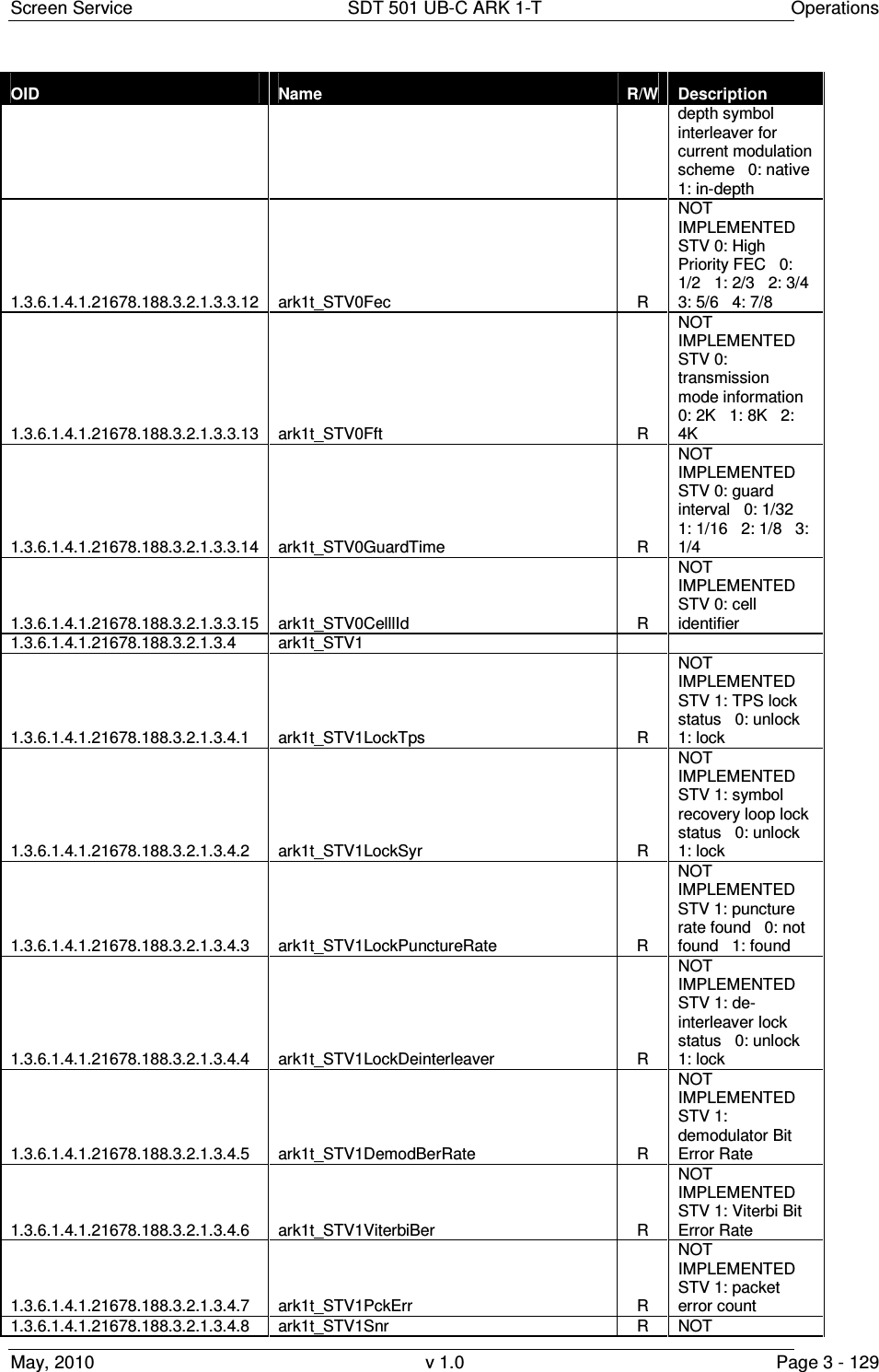
![Screen Service SDT 501 UB-C ARK 1-T Operations May, 2010 v 1.0 Page 3 - 144 OID Name R/W Description 1.3.6.1.4.1.21678.188.5.2.2 ark1t_SettingsItu_Audio 1.3.6.1.4.1.21678.188.5.2.2.1 ark1t_SettingsItu_Audio_Deviation RW Audio deviation level (range 0 to 255) 1.3.6.1.4.1.21678.188.5.2.2.2 ark1t_SettingsItu_Audio_CarrierLevel1 RW Carrier Level 1 [dB] (range: -7 to -22) = [-1* (x/10)] (range 70 to 220) 1.3.6.1.4.1.21678.188.5.2.2.3 ark1t_SettingsItu_Audio_CarrierLevel2 RW Carrier Level 2 [dB] (range: -7 to -22) = [-1* (x/10)] (range 70 to 220) 1.3.6.1.4.1.21678.188.5.2.2.4 ark1t_SettingsItu_Audio_Emphasis R Monitor emphasis 0: 50 us 1: 75 us 2: no emphasis 3: no emphasis 1.3.6.1.4.1.21678.188.5.2.2.5 ark1t_SettingsItu_Audio_Type RW Select Audio type 0: mono dual carrier 1: dual sound 2: stereo 3: mono single carrier 1.3.6.1.4.1.21678.188.5.2.2.6 ark1t_SettingsItu_Audio_TestCarriersMute RW Enable/Disable audio carriers 0: audio carriers disabled 1: audio carrier1 disabled 2: audio carrier2 disabled 3: audio carriers enabled 1.3.6.1.4.1.21678.188.5.2.2.7 ark1t_SettingsItu_Audio_SoundSystem RW D,K / PAL Sound System selector 0: FM 6.5/FM 6.742 1: FM 6.5/FM 6.258 1.3.6.1.4.1.21678.188.5.2.2.8 ark1t_SettingsItu_Audio_EmphasisDisable RW Enable/Disable Audio Emphasis 0: enabled 1: disabled 1.3.6.1.4.1.21678.188.5.2.3 ark1t_SettingsItu_Teletext 1.3.6.1.4.1.21678.188.5.2.3.1 ark1t_SettingsItu_Teletext_ReplaceEn RW NOT IMPLEMENTED Teletext replace enable 0: disabled 1: enabled 1.3.6.1.4.1.21678.188.5.2.3.2 ark1t_SettingsItu_Teletext_TxtPid RW NOT IMPLEMENTED Teletext PID 1.3.6.1.4.1.21678.188.5.2.4 ark1t_SettingsItu_GroupDelay 1.3.6.1.4.1.21678.188.5.2.4.1 ark1t_SettingsItu_GroupDelay_Bypass RW Bypass group delay filter 0: use filter 1: bypass 1.3.6.1.4.1.21678.188.5.2.4.2 ark1t_SettingsItu_GroupDelay_CurveSelector RW Mode selector for group delay filter 0: Curve A 1: Curve B 1.3.6.1.4.1.21678.188.6 ark1t_Output 1.3.6.1.4.1.21678.188.6.1 ark1t_OutputSettings 1.3.6.1.4.1.21678.188.6.1.1 ark1t_OutputSettingsA 1.3.6.1.4.1.21678.188.6.1.1.1 ark1t_SettingsAChannel RW Mode A: output channel 1.3.6.1.4.1.21678.188.6.1.1.2 ark1t_SettingsAFrequencyOffset RW Mode A: output frequency offset expressed in Hz (from -4,000,000](https://usermanual.wiki/Screen-Service-Broadcasting-Technologies/SDT501UBCARK1T.User-Manual-Part-Three/User-Guide-1390839-Page-144.png)
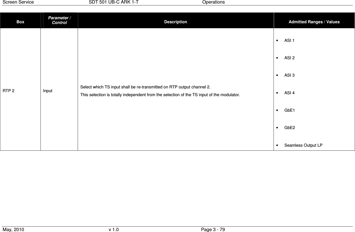
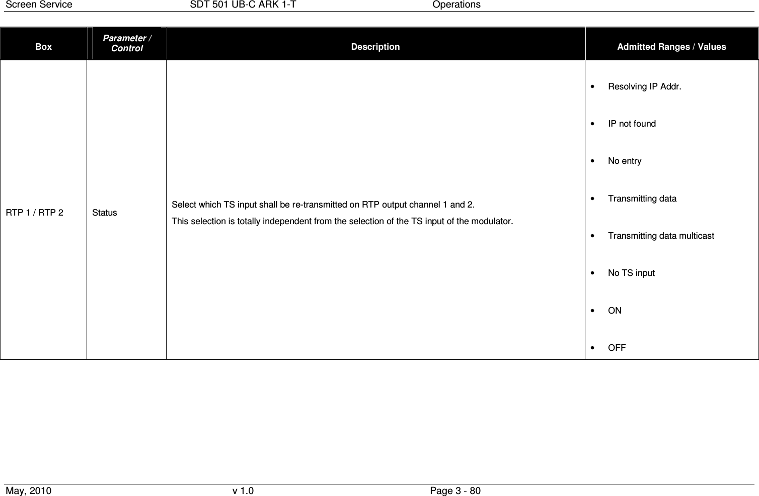
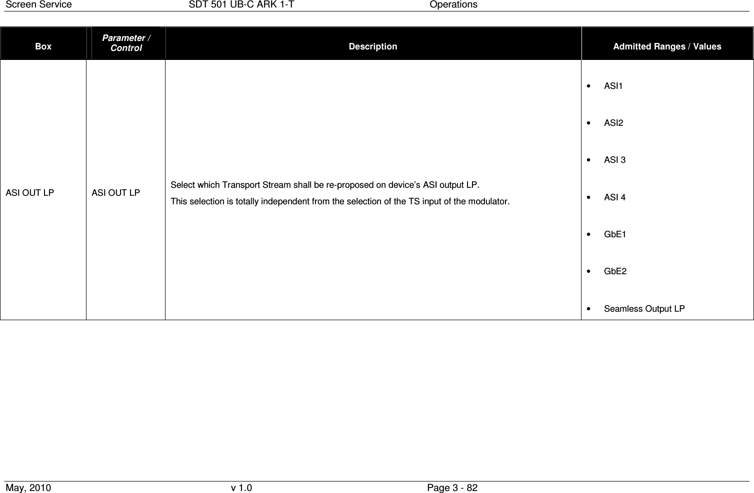
![Screen Service SDT 501 UB-C ARK 1-T Operations May, 2010 v 1.0 Page 3 - 145 OID Name R/W Description up to 4,000,000) 1.3.6.1.4.1.21678.188.6.1.1.3 ark1t_SettingsAPower RW Mode A: output power [dBm x 10] 1.3.6.1.4.1.21678.188.6.1.2 ark1t_OutputSettingsB 1.3.6.1.4.1.21678.188.6.1.2.1 ark1t_SettingsBChannel RW Mode B: output channel 1.3.6.1.4.1.21678.188.6.1.2.2 ark1t_SettingsBFrequencyOffset RW Mode B: output frequency offset expressed in Hz (from -4,000,000 up to 4,000,000) 1.3.6.1.4.1.21678.188.6.1.2.3 ark1t_SettingsBPower RW Mode B: output power [dBm x 10] 1.3.6.1.4.1.21678.188.6.1.3 ark1t_OutputSettingsGbe 1.3.6.1.4.1.21678.188.6.1.3.1 ark1t_SettingsGbeTxCh1 1.3.6.1.4.1.21678.188.6.1.3.1.1 ark1t_GbeTxCh1Selector RW Input to GbE Tx Ch 1 selector 0: asi 1 1: asi 2 2: asi 3 3: asi 4 6: Gbe Channel 1 7: Gbe Channel 2 8: Seamless HP 1.3.6.1.4.1.21678.188.6.1.3.1.2 ark1t_GbeTxCh1Status R Tx channel 1: transmission status 0: off 1: Resolving IP 2: No entry error 3: TX data 4: IP address not found 5: TX multicast data 6: No TS input error 1.3.6.1.4.1.21678.188.6.1.3.1.3 ark1t_GbeTxCh1Enable RW Tx channel 1: transmission enable 0: disabled 1: enabled 1.3.6.1.4.1.21678.188.6.1.3.2 ark1t_SettingsGbeTxCh2 1.3.6.1.4.1.21678.188.6.1.3.2.1 ark1t_GbeTxCh2Selector RW Input to GbE Tx Ch 2 selector 0: asi 1 1: asi 2 2: asi 3 3: asi 4 6: Gbe Channel 1 7: Gbe Channel 2 8: Seamless LP 1.3.6.1.4.1.21678.188.6.1.3.2.2 ark1t_GbeTxCh2Status R Tx channel 2: transmission status 0: off 1: Resolving IP 2: No entry error 3: TX data 4: IP address not found 5: TX multicast data 6: No TS input error 1.3.6.1.4.1.21678.188.6.1.3.2.3 ark1t_GbeTxCh2Enable RW Tx channel 2: transmission enable 0: disabled 1: enabled 1.3.6.1.4.1.21678.188.6.1.4 ark1t_OutputSettingsASI 1.3.6.1.4.1.21678.188.6.1.4.1 ark1t_InputToAsiOutHP RW Input to ASI output HP selector 0: asi 1 1: asi 2 2: asi 3 3: asi 4 6:](https://usermanual.wiki/Screen-Service-Broadcasting-Technologies/SDT501UBCARK1T.User-Manual-Part-Three/User-Guide-1390839-Page-145.png)
![Screen Service SDT 501 UB-C ARK 1-T Operations May, 2010 v 1.0 Page 3 - 146 OID Name R/W Description Gbe Channel 1 7: Gbe Channel 2 8: Seamless HP 1.3.6.1.4.1.21678.188.6.1.4.2 ark1t_InputToAsiOutLP RW Input to ASI output LP selector 0: asi 1 1: asi 2 2: asi 3 3: asi 4 6: Gbe Channel 1 7: Gbe Channel 2 8: Seamless LP 1.3.6.1.4.1.21678.188.6.2 ark1t_OutputRf 1.3.6.1.4.1.21678.188.6.2.1 ark1t_RfOn RW RF output enable 0: disabled 1: enabled 1.3.6.1.4.1.21678.188.6.2.2 ark1t_RfStatus R RF output status 0: off 1: on 1.3.6.1.4.1.21678.188.6.2.3 ark1t_RfPrecCurveMode R Pre-correction curve editing status 0: auto 1: manual 1.3.6.1.4.1.21678.188.6.2.4 ark1t_RfPrecCurvePort5kStatus R Port 5000 status 0: closed 1: opened 1.3.6.1.4.1.21678.188.6.2.5 ark1t_RfPrecCurveActualNumber R Current pre-correction curve number 1.3.6.1.4.1.21678.188.6.2.6 ark1t_RfManualCurveSet RW Sets the precorrection curve number when the device is in Driver mode 0...6: Curve number from 1 up to 7 255: Flat curve 1.3.6.1.4.1.21678.188.6.3 ark1t_OutputTest 1.3.6.1.4.1.21678.188.6.3.1 ark1t_TestCw RW Test CW 0: disabled 1: enabled 1.3.6.1.4.1.21678.188.6.3.2 ark1t_Test_Dvb 1.3.6.1.4.1.21678.188.6.3.2.1 ark1t_TestHole RW Test Hole 0: disabled 1: enabled 1.3.6.1.4.1.21678.188.6.3.2.2 ark1t_TestForceNullPck RW Force null packets 0: disabled 1: enabled 1.3.6.1.4.1.21678.188.6.3.3 ark1t_Test_Itu 1.3.6.1.4.1.21678.188.6.3.3.1 ark1t_Test_Cw_Av RW Test CW A/V enable 0: disabled 1: enabled 1.3.6.1.4.1.21678.188.6.3.3.2 ark1t_Test_Video RW Test video selector 0: bars 1: no video test 1.3.6.1.4.1.21678.188.6.3.3.3 ark1t_Test_Audio RW Test audio selector 0: no audio test 1: test tone 1.3.6.1.4.1.21678.188.6.3.3.4 ark1t_Test_Tone_Right RW Right tone frequency (range:0 to127) [unit x 100Hz] 1.3.6.1.4.1.21678.188.6.3.3.5 ark1t_Test_Tone_Left RW Left tone frequency (range:0 to127) [unit x](https://usermanual.wiki/Screen-Service-Broadcasting-Technologies/SDT501UBCARK1T.User-Manual-Part-Three/User-Guide-1390839-Page-146.png)
![Screen Service SDT 501 UB-C ARK 1-T Operations May, 2010 v 1.0 Page 3 - 147 OID Name R/W Description 100Hz] 1.3.6.1.4.1.21678.188.6.3.3.6 ark1t_Test_Mute_Audio_Enable RW Mute audio enable 0: disabled 1: enabled 1.3.6.1.4.1.21678.188.6.3.3.7 ark1t_Test_Itu_Its 1.3.6.1.4.1.21678.188.6.3.3.7.1 ark1t_Test_Its_enable RW Enable ITS 0: disabled 1: enabled 1.3.6.1.4.1.21678.188.6.3.3.7.2 ark1t_Test_Its0 RW ITS number 0 position (range: 7 to 622) 1.3.6.1.4.1.21678.188.6.3.3.7.3 ark1t_Test_Its1 RW ITS number 1 position (range: 7 to 622) 1.3.6.1.4.1.21678.188.6.3.3.7.4 ark1t_Test_Its2 RW ITS number 2 position (range: 7 to 622) 1.3.6.1.4.1.21678.188.6.3.3.7.5 ark1t_Test_Its3 RW ITS number 3 position (range: 7 to 622) 1.3.6.1.4.1.21678.188.6.3.3.7.6 ark1t_Test_Its4 RW ITS number 4 position (range: 7 to 622) 1.3.6.1.4.1.21678.188.6.4 ark1t_OutputTsProcessing 1.3.6.1.4.1.21678.188.6.4.1 ark1t_TsProcessingDeleteNullPck RW Delete null packets enable 0: disabled 1: enable 1.3.6.1.4.1.21678.188.6.4.2 ark1t_TsProcessingPcrRestamping RW PCR restamping enable 0: disabled 1: enable 1.3.6.1.4.1.21678.188.6.5 ark1t_OutputModulator_monitor 1.3.6.1.4.1.21678.188.6.5.1 ark1t_modulator_monitor_time_offset R Used time offset [100ns] indicator 1.3.6.1.4.1.21678.188.6.5.2 ark1t_modulator_monitor_constallation R Used constellation indicator 0: QPSK 1: 16-QAM 2: 64-QAM 1.3.6.1.4.1.21678.188.6.5.3 ark1t_modulator_monitor_alpha R Used alpha indicator 0: not hierarchical 1: alpha=1 2: alpha=2 3: alpha=4 1.3.6.1.4.1.21678.188.6.5.4 ark1t_modulator_monitor_guard_time R Used guard time indicator 0: 1/32 1: 1/16 2: 1/8 3: 1/4 1.3.6.1.4.1.21678.188.6.5.5 ark1t_modulator_monitor_fft R Used transmission mode indicator 0:2K 1:8K 2:4K 1.3.6.1.4.1.21678.188.6.5.6 ark1t_modulator_monitor_bandwidth R Used bandwidth indicator 0: 7MHz 1: 8MHz 2: 6MHz 3: 5MHz 1.3.6.1.4.1.21678.188.6.5.7 ark1t_modulator_monitor_frequency_center R Center Frequency indicator (expressed in Hz) 1.3.6.1.4.1.21678.188.6.5.8 ark1t_modulator_monitor_frequency_offset R Used frequency offset indicator 1.3.6.1.4.1.21678.188.6.5.9 ark1t_modulator_monitor_cell_id R Used Cell id indicator 1.3.6.1.4.1.21678.188.6.5.10 ark1t_modulator_monitor_cell_id_en R Cell id enable status indicator 0:](https://usermanual.wiki/Screen-Service-Broadcasting-Technologies/SDT501UBCARK1T.User-Manual-Part-Three/User-Guide-1390839-Page-147.png)
![Screen Service SDT 501 UB-C ARK 1-T Operations May, 2010 v 1.0 Page 3 - 148 OID Name R/W Description disabled 1: enabled 1.3.6.1.4.1.21678.188.6.5.11 ark1t_modulator_monitor_interleaver R Used symbol interleaver indicator 0: native 1: in-depth 1.3.6.1.4.1.21678.188.6.5.12 ark1t_modulator_monitor_system_delay R System delay indicator [100ns] 1.3.6.1.4.1.21678.188.6.5.13 ark1t_modulator_monitor_HP_network_delay R HP seamles input selected Network delay [100ns] indicator 1.3.6.1.4.1.21678.188.6.5.14 ark1t_modulator_monitor_Fec 1.3.6.1.4.1.21678.188.6.5.14.1 ark1t_FecHp R FEC high priority used 0: 1/2 1: 2/3 2: 3/4 3: 5/6 4: 7/8 1.3.6.1.4.1.21678.188.6.5.14.2 ark1t_FecLp R FEC low priority used 0: 1/2 1: 2/3 2: 3/4 3: 5/6 4: 7/8 1.3.6.1.4.1.21678.188.6.5.15 ark1t_modulator_monitor_MpeFec 1.3.6.1.4.1.21678.188.6.5.15.1 ark1t_modulator_monitor_MpeFecHp R High priority MPE-FEC 0: not used 1: used 1.3.6.1.4.1.21678.188.6.5.15.2 ark1t_modulator_monitor_MpeFecLp R Low priority MPE-FEC 0: not used 1: used 1.3.6.1.4.1.21678.188.6.5.16 ark1t_modulator_monitor_TimeSlicing 1.3.6.1.4.1.21678.188.6.5.16.1 ark1t_modulator_monitor_TimeSlicingHp R Modulator High priority time slicing 0: not used 1: used 1.3.6.1.4.1.21678.188.6.5.16.2 ark1t_modulator_monitor_TimeSlicingLp R Modulator Low priority time slicing 0: not used 1: used 1.3.6.1.4.1.21678.188.6.5.17 ark1t_modulator_monitor_LP_network_delay R LP seamles input selected Network delay [100ns] indicator 1.3.6.1.4.1.21678.188.6.5.18 ark1t_modulator_monitor_device_delay R Device delay [100ns] indicator 1.3.6.1.4.1.21678.188.6.6 ark1t_OutputMonitor 1.3.6.1.4.1.21678.188.6.6.1 ark1t_Monitor_FwdPowerDbm R Forward power [dBm x 10] indicator 1.3.6.1.4.1.21678.188.6.6.2 ark1t_Monitor_AgcMode R NOT IMPLEMENTED AGC mode status 0: analog 1: digital 1.3.6.1.4.1.21678.188.6.6.3 ark1t_Monitor_AgcOn R Auto AGC status 0: off 1: on 1.3.6.1.4.1.21678.188.6.7 ark1t_OutputPower 1.3.6.1.4.1.21678.188.6.7.1 ark1t_PowerMode R NOT IMPLEMENTED (Output power mode indicator 0: local 1: MIP) 1.3.6.1.4.1.21678.188.6.7.2 ark1t_FromMip 1.3.6.1.4.1.21678.188.6.7.2.1 ark1t_mipActual R NOT IMPLEMENTED (Actual Mip power [dBm x 10])](https://usermanual.wiki/Screen-Service-Broadcasting-Technologies/SDT501UBCARK1T.User-Manual-Part-Three/User-Guide-1390839-Page-148.png)
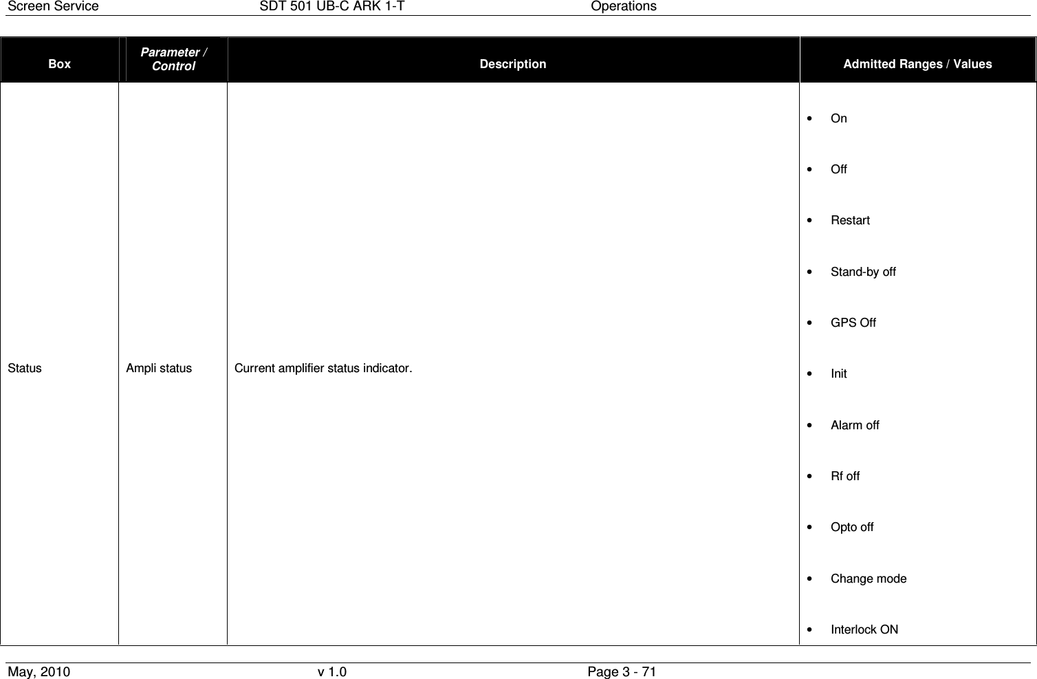
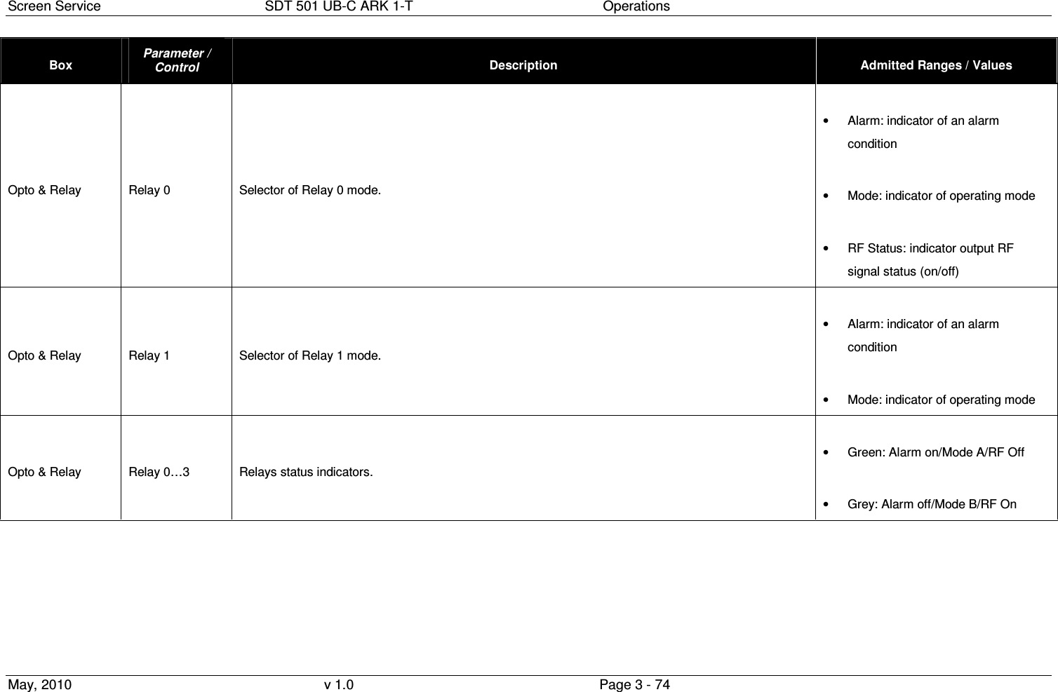
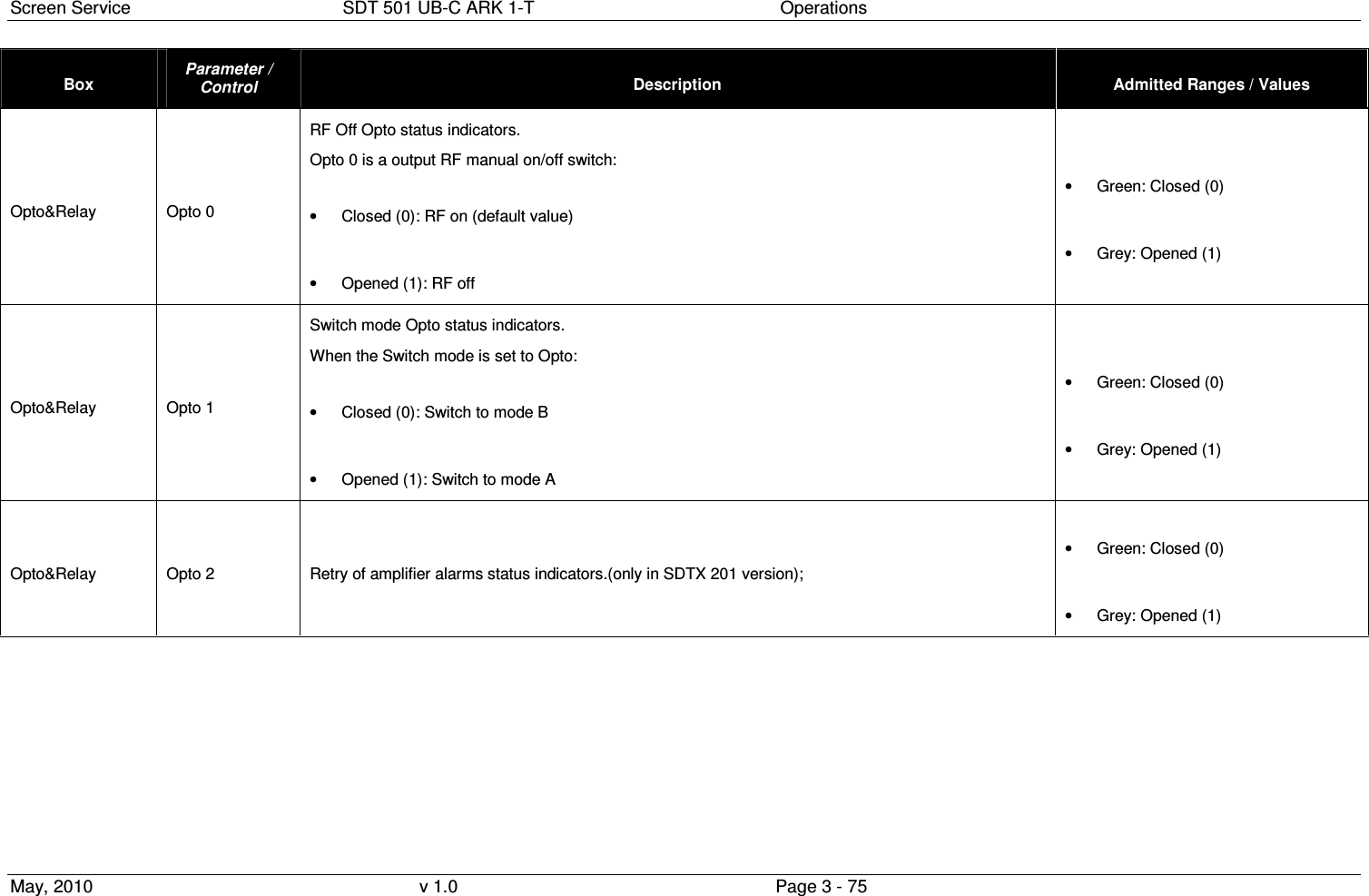
![Screen Service SDT 501 UB-C ARK 1-T Operations May, 2010 v 1.0 Page 3 - 149 OID Name R/W Description 1.3.6.1.4.1.21678.188.6.7.2.2 ark1t_mipAntennaGain NOT IMPLEMENTED (Mip antenna gain) 1.3.6.1.4.1.21678.188.7 ark1t_HW_monitor 1.3.6.1.4.1.21678.188.7.1 ark1t_HW_monitor_RflPowerDbm R Reflex power [dBm x 10] 1.3.6.1.4.1.21678.188.7.2 ark1t_HW_monitor_Amplifier R Amplifier status 0: on 1: off 2: restart 3: standby off 4: GPS off 5: init 6: alarm off 7: rf off 8: opto off 9: change mode 1.3.6.1.4.1.21678.188.7.3 ark1t_HW_monitor_CurrentOut R Current indicator (mA) 28/42V 1.3.6.1.4.1.21678.188.7.4 ark1t_HW_monitor_PowerSupply R Voltage indicator (mV): 28V for 20W and 50W versions, and 42V for 200/500W version 1.3.6.1.4.1.21678.188.7.5 ark1t_HW_monitor_PowerSupply24V R 24V voltage indicator (mV), only in 200/500W version 1.3.6.1.4.1.21678.188.7.6 ark1t_HW_monitor_FanPulse 1.3.6.1.4.1.21678.188.7.6.1 ark1t_FanSpeed1 R FAN 1 speed (rpm) 1.3.6.1.4.1.21678.188.7.6.2 ark1t_FanSpeed2 R FAN 2 speed (rpm) 1.3.6.1.4.1.21678.188.7.6.3 ark1t_FanSpeed3 R FAN 3 speed (rpm) - only for 200W/500W version 1.3.6.1.4.1.21678.188.7.6.4 ark1t_FanSpeed4 R FAN 4 speed (rpm) - only for 200W/500W version 1.3.6.1.4.1.21678.188.7.7 ark1t_HW_monitor_Temperature 1.3.6.1.4.1.21678.188.7.7.1 ark1t_TemperatureCase R Case temperature 1.3.6.1.4.1.21678.188.7.7.2 ark1t_TemperaturePsu R PSU temperature 1.3.6.1.4.1.21678.188.7.7.3 ark1t_TemperatureCase2 R Case temperature 2 (only in SDTX 200/300 version) 1.3.6.1.4.1.21678.188.7.8 ark1t_HW_monitor_Relays 1.3.6.1.4.1.21678.188.7.8.1 ark1t_Relay0Status R Relay 0 status 0: on 1: off 1.3.6.1.4.1.21678.188.7.8.2 ark1t_Relay1Status R Relay 1 status 0: on 1: off 1.3.6.1.4.1.21678.188.7.8.3 ark1t_Relay2Status R Relay 2 status 0: on 1: off 1.3.6.1.4.1.21678.188.7.8.4 ark1t_Relay3Status R Relay 3 status 0: on 1: off 1.3.6.1.4.1.21678.188.7.9 ark1t_HW_monitor_Opto 1.3.6.1.4.1.21678.188.7.9.1 ark1t_Opto0Status R Opto 0 status (RF Off): if closed the output RF is switch off 0: closed 1: opened 1.3.6.1.4.1.21678.188.7.9.2 ark1t_Opto1Status R Opto 1 status (Mode Switch): if closed Mode B, otherwise Mode A 0: closed 1: opened](https://usermanual.wiki/Screen-Service-Broadcasting-Technologies/SDT501UBCARK1T.User-Manual-Part-Three/User-Guide-1390839-Page-149.png)
![Screen Service SDT 501 UB-C ARK 1-T Operations May, 2010 v 1.0 Page 3 - 150 OID Name R/W Description 1.3.6.1.4.1.21678.188.7.9.3 ark1t_Opto2Status R Opto 2 status (Retry, only in 200 watt version) 0: closed 1: opened 1.3.6.1.4.1.21678.188.7.9.4 ark1t_Optoy3Status R Opto 3 status (Stand-by): if closed the device is put on stand-by 0: closed 1: opened 1.3.6.1.4.1.21678.188.7.9.10 ark1t_HW_monitor_PS2_CurrentOut R PS2 Current indicator (mA) 28/42V 1.3.6.1.4.1.21678.188.7.9.11 ark1t_HW_monitor_PS2_PowerSupply R PS2 Voltage indicator (mV): 28V for 20W and 50W versions, and 42V for 200/500W version 1.3.6.1.4.1.21678.188.7.9.12 ark1t_HW_monitor_PS2_PowerSupply24V R PS2 24V voltage indicator (mV), only in 200/500W version 1.3.6.1.4.1.21678.188.8 ark1t_Gps 1.3.6.1.4.1.21678.188.8.1 ark1t_GpsSat 1.3.6.1.4.1.21678.188.8.1.1 ark1t_SatVisible R Number of visible satellite 1.3.6.1.4.1.21678.188.8.1.2 ark1t_SatTracked R Number of satellite locked 1.3.6.1.4.1.21678.188.8.2 ark1t_GpsStatus 1.3.6.1.4.1.21678.188.8.2.1 ark1t_StatusDataValid R Signal precision status 0: Not valid 1: Valid 1.3.6.1.4.1.21678.188.8.3 ark1t_GpsPosition 1.3.6.1.4.1.21678.188.8.3.1 ark1t_PositionLatitude R Latitude position [░] 1.3.6.1.4.1.21678.188.8.3.2 ark1t_PositionLongitude R Longitude position [░] 1.3.6.1.4.1.21678.188.8.4 ark1t_GpsTime 1.3.6.1.4.1.21678.188.8.4.1 ark1t_TimeActual R UTC time 1.3.6.1.4.1.21678.188.8.4.2 ark1t_TimeDate R UTC date 1.3.6.1.4.1.21678.188.9 ark1t_Clock 1.3.6.1.4.1.21678.188.9.1 ark1t_ClockSel10MhzReference RW 10 MHz frequency reference 0: ext 1: int 2: gps 1.3.6.1.4.1.21678.188.9.2 ark1t_ClockSel1Pps RW 1PPS frequency reference 0: int 1: ext 1.3.6.1.4.1.21678.188.9.3 ark1t_GainFineTuning RW Gain fine tuning (from 0 up to 255) 1.3.6.1.4.1.21678.188.10 ark1t_Network 1.3.6.1.4.1.21678.188.10.1 ark1t_NetworkManagement 1.3.6.1.4.1.21678.188.10.1.1 ark1t_ManagementMacAddress R Board MAC address 1.3.6.1.4.1.21678.188.10.1.2 ark1t_ManagementIpAddress R Board IP address 1.3.6.1.4.1.21678.188.10.1.3 ark1t_ManagementNetmask R Subnet mask 1.3.6.1.4.1.21678.188.10.1.4 ark1t_ManagementGateway R Gateway address 1.3.6.1.4.1.21678.188.10.1.5 ark1t_ManagementUdpPort RW UDP port (the range is 0:65535) 1.3.6.1.4.1.21678.188.10.1.6 ark1t_ManagementSpeed R GBE Speed 0: 10 Mbit 1: 100 Mbit 2: 1 Gbit 1.3.6.1.4.1.21678.188.10.2 ark1t_NetworkIgmp 1.3.6.1.4.1.21678.188.10.2.1 ark1t_IgmpEnable RW IGMP enable 0:](https://usermanual.wiki/Screen-Service-Broadcasting-Technologies/SDT501UBCARK1T.User-Manual-Part-Three/User-Guide-1390839-Page-150.png)
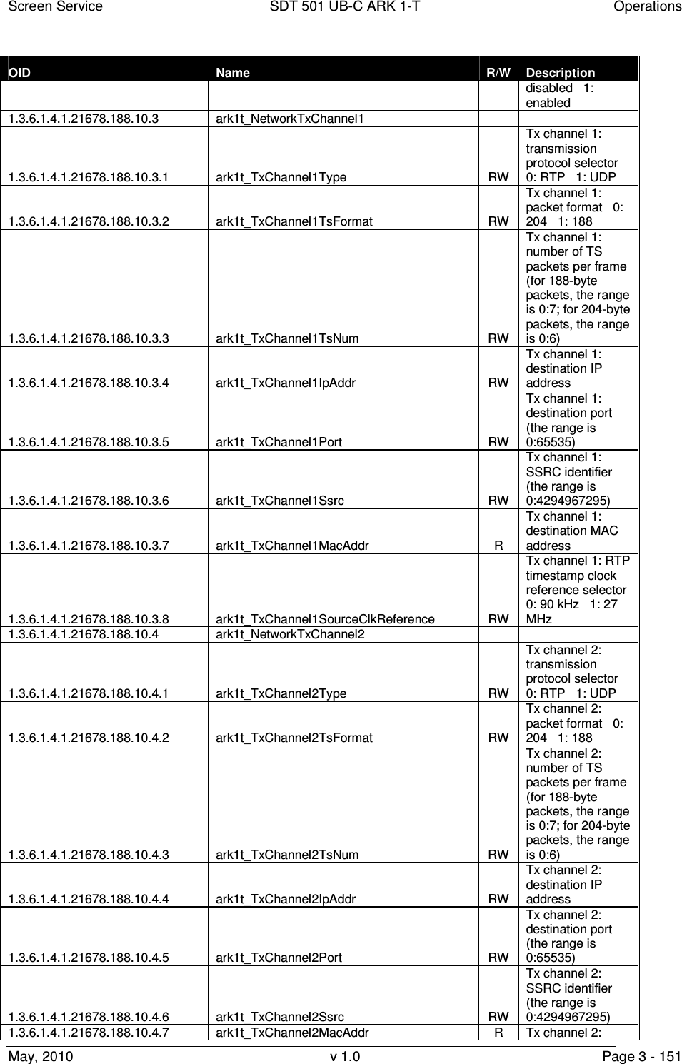
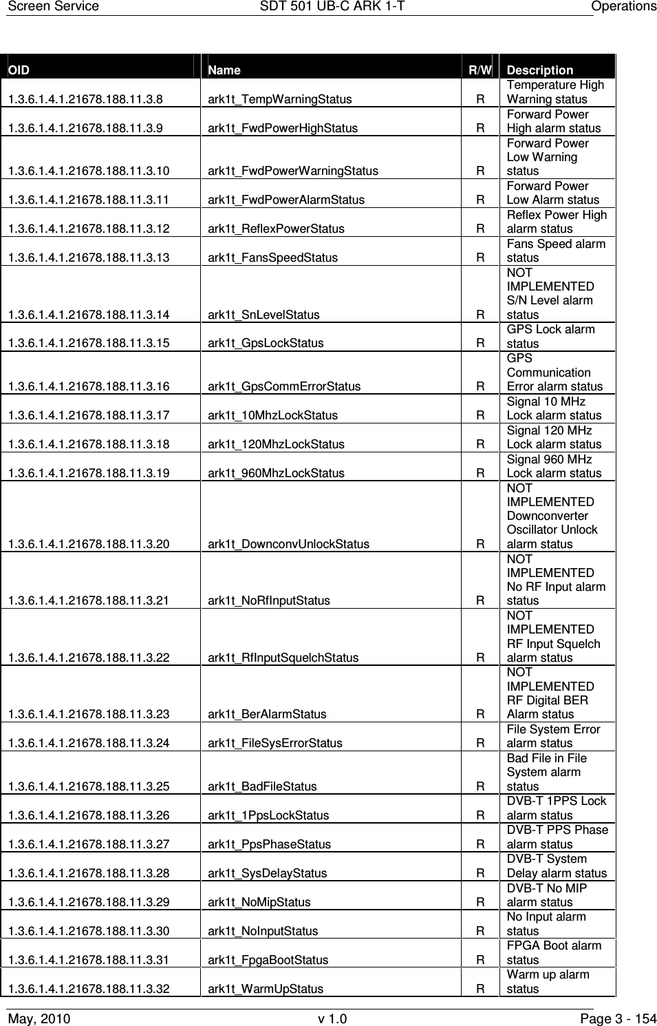
![Screen Service SDT 501 UB-C ARK 1-T Operations May, 2010 v 1.0 Page 3 - 153 OID Name R/W Description IMPLEMENTED Mode A: Squelch threshold (absolute value) 1.3.6.1.4.1.21678.188.11.1.3 ark1t_ThrRfSquelchB RW NOT IMPLEMENTED Mode B: Squelch threshold (absolute value) 1.3.6.1.4.1.21678.188.11.1.4 ark1t_ThrFwdPowerWarning RW Forward power warning threshold (absolute value [dBm x 10] ) 1.3.6.1.4.1.21678.188.11.1.5 ark1t_ThrFwdPowerAlarm RW Forward power alarm threshold (absolute value [dBm x 10]) 1.3.6.1.4.1.21678.188.11.1.6 ark1t_ThrTemperatureWarning RW Case temperature warning threshold 1.3.6.1.4.1.21678.188.11.1.7 ark1t_ThrTemperatureAlarm RW Case temperature alarm threshold 1.3.6.1.4.1.21678.188.11.1.8 ark1t_ThrSNmodeA RW NOT IMPLEMENTED Mode A: S/N threshold (dBm 10-50) 1.3.6.1.4.1.21678.188.11.1.9 ark1t_ThrSNmodeB RW NOT IMPLEMENTED Mode B: S/N threshold (dBm 10-50) 1.3.6.1.4.1.21678.188.11.1.10 ark1t_MipAlarmDelay RW MIP missing alarm delay [val * 100 ms]. The range is 1:255 (from 0,1 s up to 25,5 s). 1.3.6.1.4.1.21678.188.11.1.11 ark1t_InputAlarmDelay RW TS input missing alarm delay [val * 100 ms]. The range is 1:255 (from 0,1 s up to 25,5 s). 1.3.6.1.4.1.21678.188.11.2 ark1t_AlarmStatus R 32 bits word indicating alarms status (each bit is associated to an alarm) 1.3.6.1.4.1.21678.188.11.3 ark1t_AlarmSingleStatus 1.3.6.1.4.1.21678.188.11.3.1 ark1t_UpconvUnlockStatus R Upconverter Oscillator Unlock alarm status 1.3.6.1.4.1.21678.188.11.3.2 ark1t_PsVoltageStatus R PS Voltage out of range alarm status 1.3.6.1.4.1.21678.188.11.3.3 ark1t_PsCurrentStatus R PS Current out of range alarm status 1.3.6.1.4.1.21678.188.11.3.4 ark1t_AbsPowerLimiterStatus R Absolute Power Limiter alarm status 1.3.6.1.4.1.21678.188.11.3.5 ark1t_CommErrorStatus R Upconverter Communication error alarm status 1.3.6.1.4.1.21678.188.11.3.6 ark1t_TempHighStatus R Temperature High Alarm status 1.3.6.1.4.1.21678.188.11.3.7 ark1t_TempAlarmStatus R Temperature Level -3dB alarm status](https://usermanual.wiki/Screen-Service-Broadcasting-Technologies/SDT501UBCARK1T.User-Manual-Part-Three/User-Guide-1390839-Page-153.png)