Screen Service Broadcasting Technologies SDT501UBCARK1T 200 Watt Multimode SDR Transmitter User Manual Part Three
Screen Service Broadcasting Technologies SpA 200 Watt Multimode SDR Transmitter Part Three
Contents
- 1. User Manual Part One
- 2. User Manual Part Two
- 3. User Manual Part Three
User Manual Part Three

Screen Service SDT 501 UB-C ARK 1-T Operations
May, 2010 v 1.0 Page 3 - 1
SDT 501 UB-C
Software Defined
Transposer/ Re-Transmitter
OPERATION MANUAL
3 OPERATIONS
CONTENTS
3.1
INSTALLATION ...................................................................................................................................... 3
3.1.1
INSTALLATION PROCEDURE CHECK OFF..................................................................................... 3
3.1.2
SITE SELECTION ............................................................................................................................... 3
3.1.2.1
MOUNTING SPECIFICATIONS .................................................................................................. 3
3.1.3
UNPACKING ....................................................................................................................................... 3
3.1.4
EQUIPMENT MOUNTING .................................................................................................................. 4
3.1.5
FRONT PANEL ................................................................................................................................... 5
3.1.5.1
REAR PANEL .............................................................................................................................. 6
3.1.5.2
REAR PANEL CONNECTORS.................................................................................................... 7
3.1.6
MULTIMETER ..................................................................................................................................... 9
3.1.7
LOCAL INTERRFACE MENU TREE ................................................................................................ 10
3.1.8
BOOT AND WELCOME MESSAGE................................................................................................. 13
3.2
IDLE MENU....................................................................................................................................... 14
3.2.1
MAIN MENU...................................................................................................................................... 15
3.3
LCD alarms ....................................................................................................................................... 16
3.4
JAVA REMOTE GRAPHIC USER INTERFACE .................................................................................. 18
3.4.1
JAVA INTERFACE OVERVIEW ....................................................................................................... 18
3.4.1.1
General ...................................................................................................................................... 20
3.4.1.2
Input ........................................................................................................................................... 21
3.4.1.3
Modes management &Seamless Switching .............................................................................. 27
3.4.2
Modes management .................................................................................................................. 28
3.4.3
Modes switching rules................................................................................................................ 33
3.4.4
HP/LP INPUT............................................................................................................................. 33
3.4.5
MODULATION .................................................................................................................................. 41
3.4.6
Modulator management ............................................................................................................. 41
3.4.7
Network Synchronization parameters setting ............................................................................ 45
3.4.8
Modulation parameters .............................................................................................................. 46
3.4.9
DVB-H parameters..................................................................................................................... 50
3.4.10
MIP functions ............................................................................................................................. 52
3.4.11
ITU functions.............................................................................................................................. 59
3.5
PRE-CORRECTION TOOL............................................................................................................... 64
3.5.1
Module&Phase........................................................................................................................... 64
3.5.2
AM/PM ....................................................................................................................................... 65
3.5.3
Connection to port 5000............................................................................................................. 67

Screen Service SDT 501 UB-C ARK 1-T Operations
May, 2010 v 1.0 Page 3 - 2
3.5.4
OUTPUT............................................................................................................................................ 68
3.6
NETWORK ........................................................................................................................................ 83
3.7
GPS................................................................................................................................................... 90
3.8
ALARMS............................................................................................................................................ 92
3.9
EVENTS .......................................................................................................................................... 103
3.9.1
Date and time setting ............................................................................................................... 107
3.9.2
Task Error Event ...................................................................................................................... 108
3.9.3
System Error Event.................................................................................................................. 109
3.9.4
System Initialization Event ....................................................................................................... 110
3.10
Option sub-menu............................................................................................................................. 116
3.10.1
Time ......................................................................................................................................... 116
3.10.2
Alerts ........................................................................................................................................ 116
3.11
Download Software Standalone...................................................................................................... 118
3.12
SNMP – Simple Network Management Protocol................................................................................ 119
3.13
SNMP Protocol Preferences ........................................................................................................... 120
3.14
Monitoring........................................................................................................................................ 121
3.15
OID .................................................................................................................................................. 122
3.15.1
SNMP tree structure ................................................................................................................ 122
3.16
Configuring alarms MASKS ........................................................................................................... 156
3.17
Traps ............................................................................................................................................... 158
3.17.1
Configuring traps...................................................................................................................... 158
3.18
AUTOMATIC FREQUENCY CONTROL ............................................................................................ 178
3.19
APPLICATION NOTE ......................................................................................................................... 180
3.19.1
How to update ................................................................................................................................. 180
3.20
Java Virtual Machine .......................................................................................................................... 185
3.21
ETHERNET CONNECTION ............................................................................................................... 185
3.21.1
Configuration ................................................................................................................................... 185
3.21.2
Java(TM) Platform........................................................................................................................... 185
3.21.3
Download ........................................................................................................................................ 185
3.21.4
Java Control Panel .......................................................................................................................... 185
3.22
SUPPORTED WEB BROWSERS ...................................................................................................... 187
3.23
SECURITY measures and systems used with the transmitter to make sure that only legal copies of
the software can be loaded on the transmitter .............................................................................................. 187

Screen Service SDT 501 UB-C ARK 1-T Operations
May, 2010 v 1.0 Page 3 - 3
3.1 INSTALLATION
3.1.1 INSTALLATION PROCEDURE CHECK OFF
Some procedures in this section contain steps preceded by a check box. Fill out or initial each step as it is
completed.
3.1.2 SITE SELECTION
Use the following specifications to establish criteria for site selection and equipment installation.
3.1.2.1 MOUNTING SPECIFICATIONS
Mount.
• A floor-standing, open rack or permanent structure with vertical mounting members conforming to
EIA Standard 310 is recommended.
Environment.
• Ambient temperature: 0°C to +45°C (room temperature or below is ideal)
• Relative humidity: 10% to 90%, non condensing
Clearance.
• No clearance is required for sides.
• At least 1 U free space above and below the equipment is recommended to obtain adequate cooling.
• Access to the front requires approximately 20 centimeters clearance for making connections.
• Access to the rear requires approximately 20 centimeters clearance for making connections.
3.1.3 UNPACKING
The containers used to ship a SDT ARK 1 transposer / re-transmitter will vary with the number of options
ordered. If there is any external damage to the containers, inform the shipping company and request that an
agent be present during unpacking. Carefully unpack the boxes (no special instructions are required) and
note any damage making pictures if possible.
After all items are unpacked, check the equipment received. If there are any damages or shortages, notify
the carrier and Screen Service BT immediately.

Screen Service SDT 501 UB-C ARK 1-T Operations
May, 2010 v 1.0 Page 3 - 4
3.1.4 EQUIPMENT MOUNTING
Install the transmitter in an EIA (Standard 310) 19 inch rack as follows:
Place the equipment into the rack (2 units), align the mounting holes, and secure in place with four rack
screws.
If configured to operate, make sure the "LINE" switch on the front panel of the POWER SUPPLY &
METERING module is OFF.
Connect the power cord to an operating power source.
Note: We warmly suggest the installation of spike suppressors, line conditioners, isolation
transformers or other devices useful to protect the equipment.
Connect the transmitting antenna cable to the "RF OUTPUT" connector in the rear panel.
Connect the, RF, GPS, ASI, SNMP PORT, AUX REMOTE, 10 MHz, 1PPS and the IF monitor to the
relevant input / output connectors on the front and rear panel.
REMEMBER TO CONNECT the equipment to the GROUND using the relevant screw located on the
rear panel.

Screen Service SDT 501 UB-C ARK 1-T Operations
May, 2010 v 1.0 Page 3 - 5
3.1.5 FRONT PANEL
1 2 3 4 5 6 7 8 9 10
ARK 1-T Front Panel
n. Label Description
1 RF INPUT
2 GPS IN
3 ASI OUTPUT HP
4 ASI OUTPUT LP
5 ASI in 1
6 ASI in 2
7 ASI in 3/ SDI in
8 ASI in 4
9 GBE 1
10 LCD Display
Screen Service SDT 501 UB-C ARK 1-T Operations
May, 2010 v 1.0 Page 3 - 6
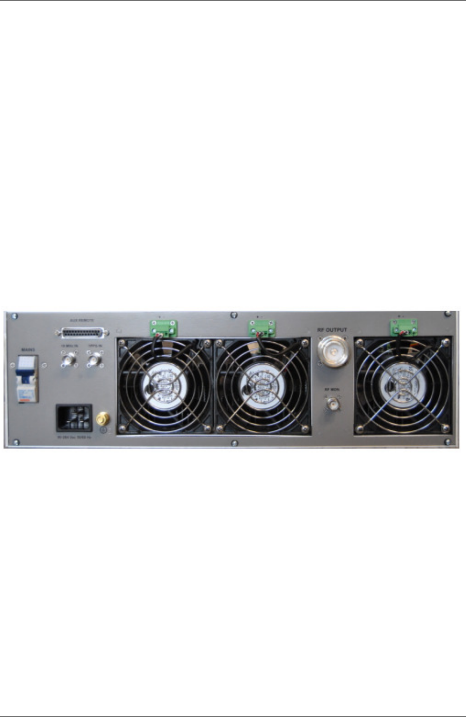
3.1.5.1 REAR PANEL
1. AC Main ON/OFF SWITCH
2. AUX REMOTE
3. FAN
4. FAN
5. RF OUTPUT
6. FAN
7. 10 MHz INPUT
8. 1 PPS INPUT
9. AC MAIN INPUT SOKET
10. GND REFERENCE
11. RF MONITOR
1 2 3 4 5 6
7 8
9 10 11
Screen Service SDT 501 UB-C ARK 1-T Operations
May, 2010 v 1.0 Page 3 - 7
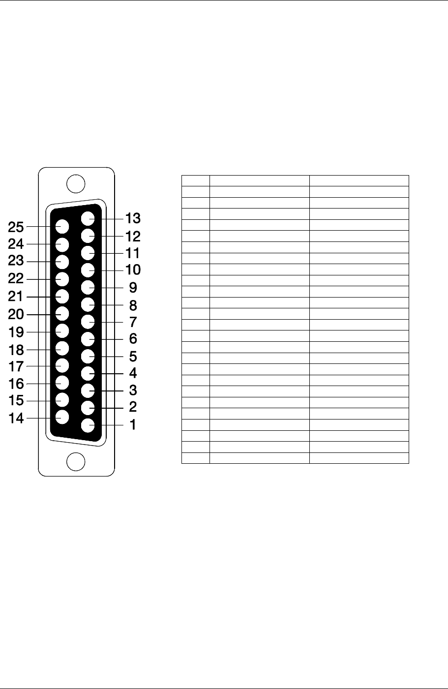
3.1.5.2 REAR PANEL CONNECTORS
AUX REMOTE CONNECTOR
Sub-D 25 Male.
PIN ASSIGNMENT REMARKS
1
2 Not used
3 Alarm reset in opto active to gnd
4 Remote STBY in opto active to gnd
5 GND OPTO
6
7
8
9 SERIAL 485/232
10 SERIAL 485/232
11
12 RF OFF in opto active to gnd
13
14
15
16
17 COM RL 0 NOR. CLOSED
18 RL 0
19 COM RL 1 NOR. CLOSED
20 RL 1
21 COM RL2 NOR. CLOSED
22 RL 2
23 COM RL 3 NOR. CLOSED
24 RL 3
25
Figure 3.1-1: AUX REMOTE CONNECTOR

Screen Service SDT 501 UB-C ARK 1-T Operations
May, 2010 v 1.0 Page 3 - 8
Screen Service SDT 501 UB-C ARK 1-T Operations
May, 2010 v 1.0 Page 3 - 9
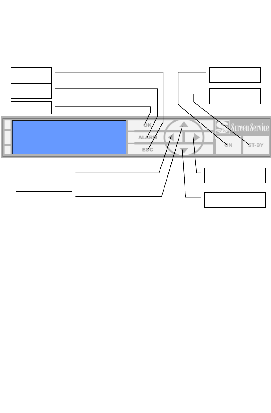
3.1.6 MULTIMETER
The following paragraphs describe the local user interface for ARK1.
This user interface is composed of LCD Display, seven buttons and two status leds.
Here below is depicted the ARK1 Front Panel.
• STAND-BY: push this button (lie in wait for two seconds) to put the equipment on
STAND-BY mode. The orange led lights up and the written STAND-BY MODE appears
on the display. The remote Stand-by mode is enforceable only if on JAVA interface this
feature is enabled.
• ON: push this button (lie in wait for two seconds) to turn on the equipment. The green
led lights up and the MAIN MENU is displayed.
• OK: push this button to select or to confirm the subwindow or the value respectively.
Touching the screen with a finger the green led lights up.
• ESC: push this button to quit a submenu and to return to the previous one. Touching the
screen with a finger the green led lights up.
• ALARM: when an alarm occurs the RED LED lights up.
• UP ARROW: push this botton to scroll up menus or to increase a value. Touching the
screen with a finger the green led lights up.
• DOWN ARROW: push this botton to scroll down menus or to decrease a value.
Touching the screen with a finger the green led lights up.
• LEFT ARROW: push this botton to move within a string. Touching the screen with a
finger the green led lights up.
• RIGHT ARROW: push this botton to move within a string. Touching the screen with a
finger the green led lights up.
OK
ALARM
ESCAPE
ON
STANB
-
BY
LEFT ARROW
UP ARROW
RIGHT ARROW
DOWN ARROW
Screen Service SDT 501 UB-C ARK 1-T Operations
May, 2010 v 1.0 Page 3 - 10
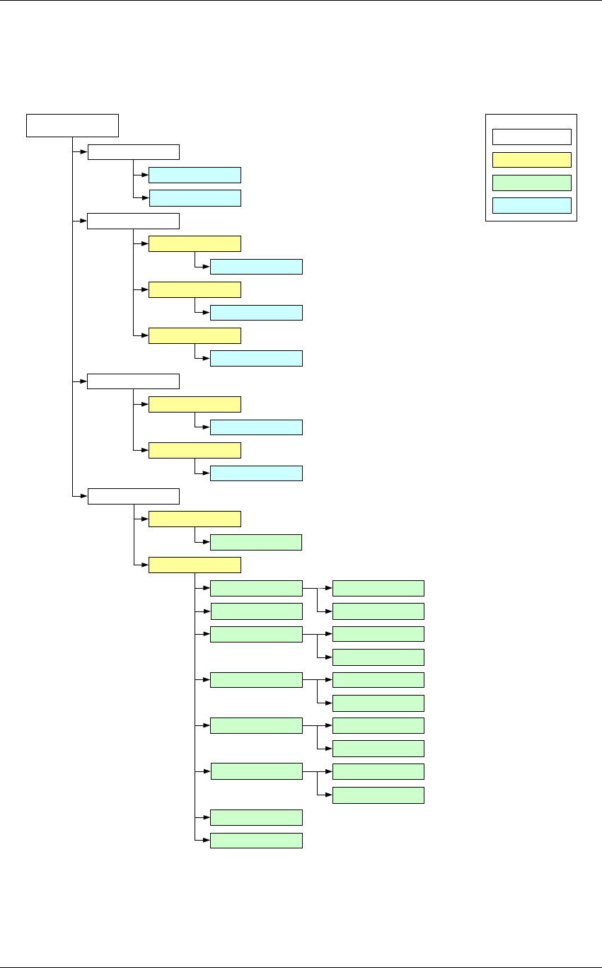
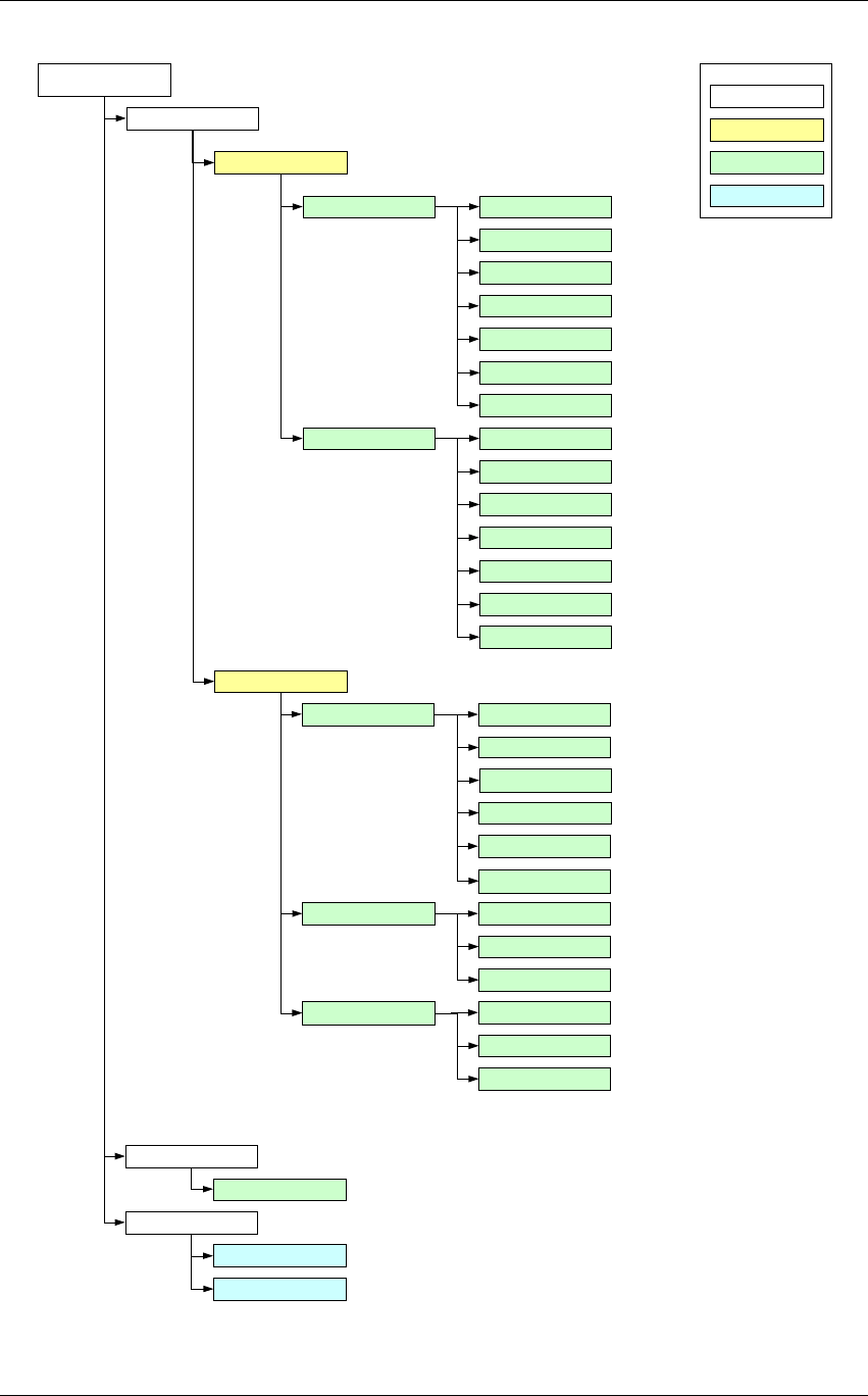
3.1.7 LOCAL INTERRFACE MENU TREE
Main display
menu
Network setup
IP addr GBE
Gateway GBE
Netmask GBE
A1:A2:A3:A4
G1:G2:G3:G4
N1:N2:N3:N4
Menu
Multiple choice
Data R
LEGEND
Data W
Time & Date setup
Date Setup
Time Setup
dd:MM:yy
H:mm:ss
System Status
System
Actual mode
Amplifier status
Power supply
Temperature
Fans speed
Real Time Clock
Optos status
Relays status
Current Mode A
Current Mode A
Voltage
Current
Case
PSU
FAN 1
FAN 2
Time
Date
Installer version
Installer version
Change mode
Mode A
Mode B

Screen Service SDT 501 UB-C ARK 1-T Operations
May, 2010 v 1.0 Page 3 - 11
Modulation
Network
Del Null Pcks
Bandwidth
Constellation
Hierarchical Mode
Interleaver
HP FEC
LP FEC
FFT
Guard Time
Cell ID
Main display
menu
System status
Time Slice HP
Time Slice LP
MPE FEC HP
MPE FEC LP
Menu
Multiple choice
Data R
LEGEND
Data W
MPE FEC LP
Delay
Frec off
Time off
Net Delay
Dev Delay
Screen Service SDT 501 UB-C ARK 1-T Operations
May, 2010 v 1.0 Page 3 - 12
Main display
menu Menu
Multiple choice
Data R
LEGEND
Data W
System status
Output
Output RF status
Frequency ref
Channel
Offset
FWD power
RFL power
RTP 1 Input
Status
RTP 2
IP Address
Input
Status
IP Address
Alarms
Alams list
Reset system
Yes
No
Input
HP input Input
Lock
Bitrate
Useful
Overflow
Format
Errors
LP input Input
Lock
Bitrate
Useful
Overflow
Format
Errors

Screen Service SDT 501 UB-C ARK 1-T Operations
May, 2010 v 1.0 Page 3 - 13
Figure 1. Local Interface Menu Tree
3.1.8 BOOT AND WELCOME MESSAGE
Turning on the equipment, the display shows the progress bar as follow:
When the boot is over, the board is ready.
Press ESC to enter the main menu, otherwise after one minute waiting the idle status message
appears.
Screen Service
ARK - DVB-T/DIG-IF
System Init
Init : [ ] Wait
Screen Service
ARK - DVB-T/DIG-IF
Boot FPGA
Init : [ ] Wait
Screen Service
ARK - DVB-T/DIG-IF
Up Converter check
Init : [ ] Wait
Screen Service
ARK - DVB-T/DIG-IF
Start system
Init : [ ] Wait
Screen Service
ARK - DVB-T/DIG-IF
Start system
Init : [ ] Ready
Screen Service
ARK - DVB-T/DIG-IF
10.77.98.44
Ready

Screen Service SDT 501 UB-C ARK 1-T Operations
May, 2010 v 1.0 Page 3 - 14
3.2 IDLE MENU
This menu appears after one minute waiting from the last touch. Information contained in the Idle Menu
are described in next table.
Table 1. Local User Interface: Idle Menu
Information Description
Operating mode
• DIGITAL IF: Heterodyne Transposer
• DVBT: Re-broadcasting DVB
Modulator
AGC Mode
(only in DIGITAL-IF mode)
• ANA: Analog
• DIG: Digital
Output Power and Channel
Dout: digital output power and channel
Aout: analog output power and channel
Out: output power and channel
UTC Time and date coming from GPS receiver
Press ESC to enter the MAIN MENU.
AR
K - DVB T
InHP: ASI1
Out 17.1dBm CH:22
UTC: 14:11 08/11/06

Screen Service SDT 501 UB-C ARK 1-T Operations
May, 2010 v 1.0 Page 3 - 15
3.2.1 MAIN MENU
This menu shows five SUBMENUS. It is possible to view them sliding the menu up and down, with the
UP or DOWN ARROWS, and to select one of them by pushing on the OK button.
Submenus contained in the Main Menu are described in next table.
Submenu Description
Network setup
Enter this submenu to change:
• Board IP address
• Gateway address
• Netmask
System Status
Enter this submenu to monitor:
• System status
• Auxiliary and RF input statistics
• Tuner status
• Output status and settings
• Actual modulation parameters
All information are refreshed every 5
seconds.
Alarms Enter this submenu to view the alarm list
Reset system Enter this submenu to reset the device.
Change mode Enter this submenu to change operating
mode (A or B).
Change Mode
Network setup
System Status
/ OK:Enter
/

Screen Service SDT 501 UB-C ARK 1-T Operations
May, 2010 v 1.0 Page 3 - 16
3.3 LCD alarms
Through the LCD Alarms mask it is possible to select which alarm has to be notified on LCD display.
The alarm button is lighted and when an alarm condition occurs, alarms status is displayed in the
Alarms submenu.
The following table lists the alarms messages displayed on LCD, associated to the corresponding alarm
(refer to Alarms paragraph for further information about alarms and their masks).
Table 2.
Alarms descriptions list
Alarm Alarm Message
Up converter Osc. Unlock UPCV not locked
PS Voltage out of range PS V out of range
PS Current out of range PS I out of range
Absolute Power Limiter Abs. pwr high
Communication error UPCV dialog error
Temperature High Alarm Temperature high
Temperature Level-3dB Temp alarm (-3dB)
Temperature High Warning Temp warning
Forward Power High FWD power high
Forward Power Low Warning FWD low warning
Forward Power Low Alarm FWD low alarm
Reflex Power High RFL power high
Fan Speed Fans warning
Input Not Present Alarm One of the two inputs of HP or LP isn’t present
GPS Lock GPS not locked
GPS Communication Error GPS dialog error
Signal 10 MHz Lock 10MHz not detected
Signal 120 MHz Lock 120MHz not detected
Signal 960 MHz Lock 960MHz not detected
Input Not Valid Errors are detected in one of the two LP or/ and HP inputs
Late MIP Alarm MIP arrives over the expected time
Network delay alarm Network delay exceeds the Maximum delay
File System Error FS wrong
Bad File in File system File error
DVB-T 1PPS Lock PPS not detected
DVB-T PPS Phase PPS phase wrong
DVB-T System Delay Sys delay wrong
DVB-T No MIP MIP not detected
No Input In. not detected

Screen Service SDT 501 UB-C ARK 1-T Operations
May, 2010 v 1.0 Page 3 - 17
Alarm Alarm Message
FPGA Boot alarm FPGA boot err
Warm up alarm
Sys. warm up

Screen Service SDT 501 UB-C ARK 1-T Operations
May, 2010 v 1.0 Page 3 - 18
3.4 JAVA REMOTE GRAPHIC USER INTERFACE
The Java Graphic User Interface, stored in the board File System, is downloaded to the local PC
every time the user connects to the board with a Web Browser. A proper Java Virtual Machine is
needed; refer to the Appendix B for a description of supported Java and Internet Browsers.
3.4.1 JAVA INTERFACE OVERVIEW
The following figure shows the main control switch of the Java User Interface. It allows the
switching between control pages for settings and monitoring the device.
Figure 2. Java main control switch
The following controls are provided:
System commands bar allows the enabling of the following commands:
• Connect: connects/disconnects the local machine to Ark1 system
• Save: allows to save the device configuration.
• Load: allows to load the last saved device configuration.
Figure 3. System commands bar
Operation pages bar allows to switch between the following operative sections:
o General: allows to enable the Stand-by mode through the LCD Button, to reset the
device and to locally download the *.jar file.
o Input: shows ASI and GBE input statistics.
o Modes Management and Seamless Switching: allows to monitor the RF input and
to configure operative modes (mode A and mode B).
o Modulation: allows to monitor and to set the DVB-T/H modulation parameters.
o Linear Precorrection allows managing linear pre-correction curves.
o AM/PM Precorrection: allows managing AM/PM pre-correction curves.
o Outputs: allows to set output parameters, specific for each operative mode, and to
monitor the hardware status.
o Network: allows the Network management and the RTP in/out parameters setting.

Screen Service SDT 501 UB-C ARK 1-T Operations
May, 2010 v 1.0 Page 3 - 19
o GPS: shows received GPS statistics.
o Alarms: provides a grid where to set alarms masks for LCD, Graphic User Interface,
Events, Relays, Traps and RF Off.
o Events: shows the board events log and allows the manual setting of date and.
Figure 4. Operation pages bar
System menu allows the access to the same commands and pages as System commands and
Operation pages bars plus management options, help and version windows (refer to Option sub-
menu paragraph).
A brief description of all the provided indicators and controls follows in the next paragraphs.
Screen Service SDT 501 UB-C ARK 1-T Operations
May, 2010 v 1.0 Page 3 - 20
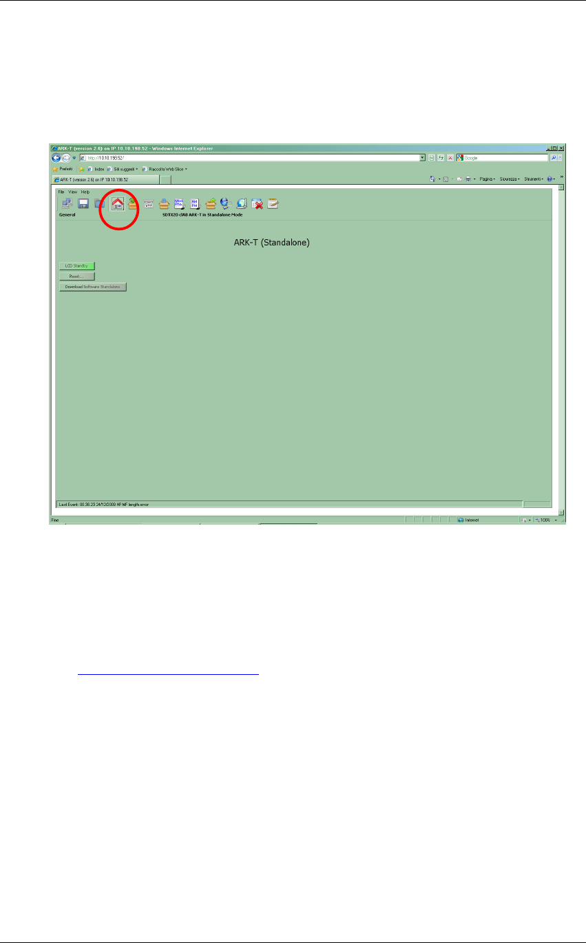
3.4.1.1 General
Click on General button icon, highlighted in the nex figure, to access the general window.
Figure 5. General window
The General window provides a general description of the device and allows the access to a
subset of commands through the following button icons:
• Reset: resets the device.
• LCD Standby: enables the LCD Stand-by button.
• Download Software Standalone: performs a local download of the *.jar file (refer to
Download Software Standalone paragraph).
Screen Service SDT 501 UB-C ARK 1-T Operations
May, 2010 v 1.0 Page 3 - 21
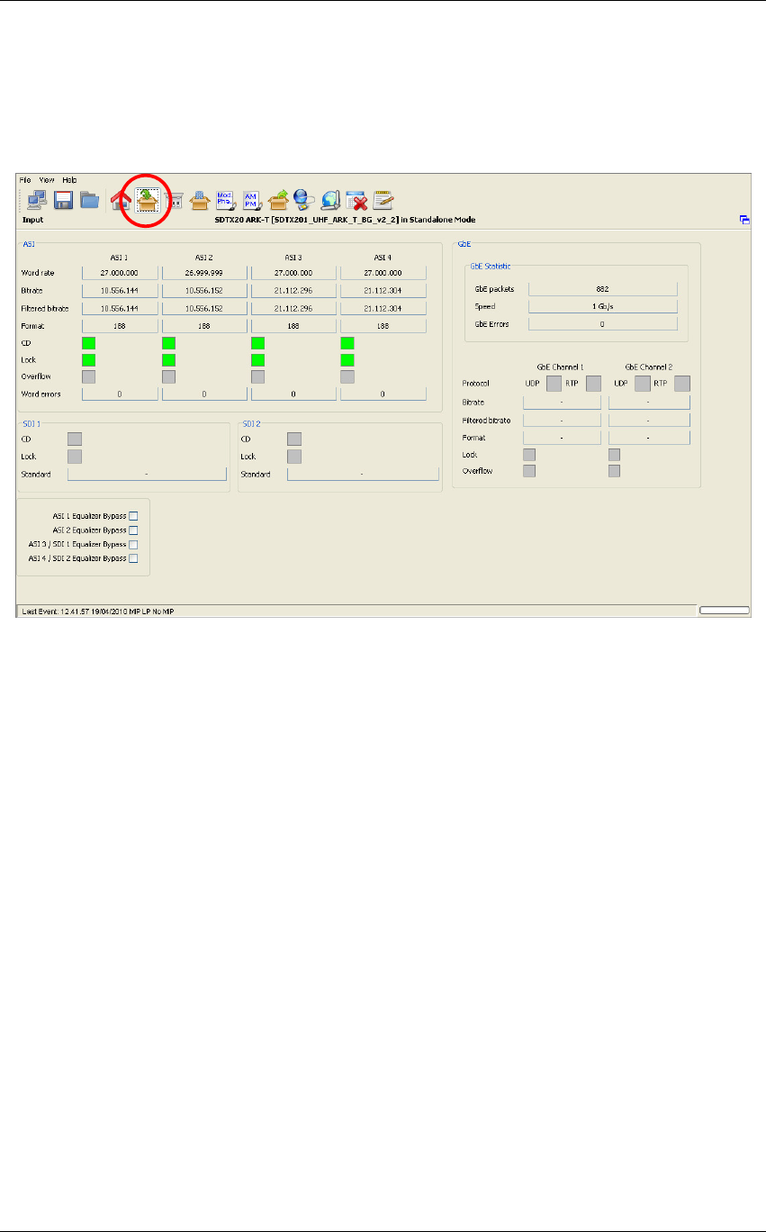
3.4.1.2 Input
Click on Input button icon, highlighted in the nex figure, to access the input statistics window.
Figure 6. Input window
The Input window allows the monitoring of auxiliary inputs of Re-broadcasting DVB-T/H
Modulator and Re-broadcasting ITU 470 modulator.
Input Transport Streams monitoring of four ASI, two RTP channels on GBE port and two SDI are
provided.

Screen Service SDT 501 UB-C ARK 1-T Operations
May, 2010 v 1.0 Page 3 - 23
Table 3. Input window
Box Parameter /
Control Description Admitted Ranges / Values
ASI Word rate ASI input word rate. 10 bits word rate of ASI input (Ref. to CEI EN 50083-9). Approximately 27 Mword/s
ASI Bit-rate
[bit/s] ASI input bit-rate.
ASI Filtered bit-
rate[bit/s]
When the ARK-T working in seamless mode the java show the filtered bit-rate of all seamless input
(seamless mode working in SFN mode only, so the bit-rate actually used by the modulator, and the
filtered bit-rate showed must be equal than the total bit-rate)
When the seamless mode is disabled the java show the bit-rate actually used by the modulator.
• Zero when the input has not been
selected
• Equal to the total bit-rate, when
Delete Null Packets disabled
• Less than total bit-rate, when Delete
Null Packets enabled
ASI Format Format of received TS Packets (Ref. to CEI EN 50083-9).
• 188 Bytes
• 240 Bytes
ASI CD ASI Carrier detect.
• Green: Detected
• Grey: Not detected

Screen Service SDT 501 UB-C ARK 1-T Operations
May, 2010 v 1.0 Page 3 - 24
Box Parameter /
Control Description Admitted Ranges / Values
ASI Lock ASI locking status. The input Transport Stream is unlocked when more than two consecutive Sync Byte
are missed then five consecutive Sync Bytes must occur to regain the lock (Ref. to ETSI ETR-291)
• Green: Locked
• Grey: Not locked
ASI Overflow ASI input overflow indicator. This alarm condition occurs when the input bit-rate exceeds the capability
of the modulation (Ref. to ETSI EN 300 744).
• Red: Alarm
• Grey: No alarms
ASI Word Errors Total amount of ASI wrong words received.
ASI/SDI Equalizer
Bypass Enable/Disable the equalization bypass of the signal received over ASI interface
• Checked: Enabled
• Not checked: Disabled
RTP Protocol Ethernet input packets protocol
. • UDP
• RTP
RTP Bit-rate
[bit/s] Bit-rate of TS from Ethernet input.

Screen Service SDT 501 UB-C ARK 1-T Operations
May, 2010 v 1.0 Page 3 - 25
Box Parameter /
Control Description Admitted Ranges / Values
RTP Filtered bit-
rate [bit/s] Bit-rate actually used by the modulator.
• Zero when the input is not selected
• Equal to the total bit-rate, when
Delete Null Packets disabled
• Less than total bit-rate, when Delete
Null Packets enabled
RTP Format Format of received TS Packets (Ref. to CEI EN 50083-9).
• 188 Bytes
• 204 Bytes
RTP Lock
Transport Stream locking status. The input Transport Stream is unlocked when more than two
consecutive Sync Byte are missed; then five consecutive Sync Bytes must occur to regain the lock (Ref.
to ETSI ETR-291)
• Green: Locked
• Grey: Not locked
RTP Overflow Input GbE overflow alarm status. This alarm condition occurs when the input bit-rate exceeds the
capability of the modulation (Ref. to ETSI EN 300 744).
• Red: Alarm on
• Grey: Alarm off
RTP GbE packets Total amount of good Ethernet frames received.

Screen Service SDT 501 UB-C ARK 1-T Operations
May, 2010 v 1.0 Page 3 - 26
Box Parameter /
Control Description Admitted Ranges / Values
RTP Speed Ethernet connection speed. No duplex information is provided.
• 10 Mbit//s
• 100 Mbit//s
• 1 Gbit//s
RTP GbE errors Total amount of bad Ethernet frames received.
Screen Service SDT 501 UB-C ARK 1-T Operations
May, 2010 v 1.0 Page 3 - 27
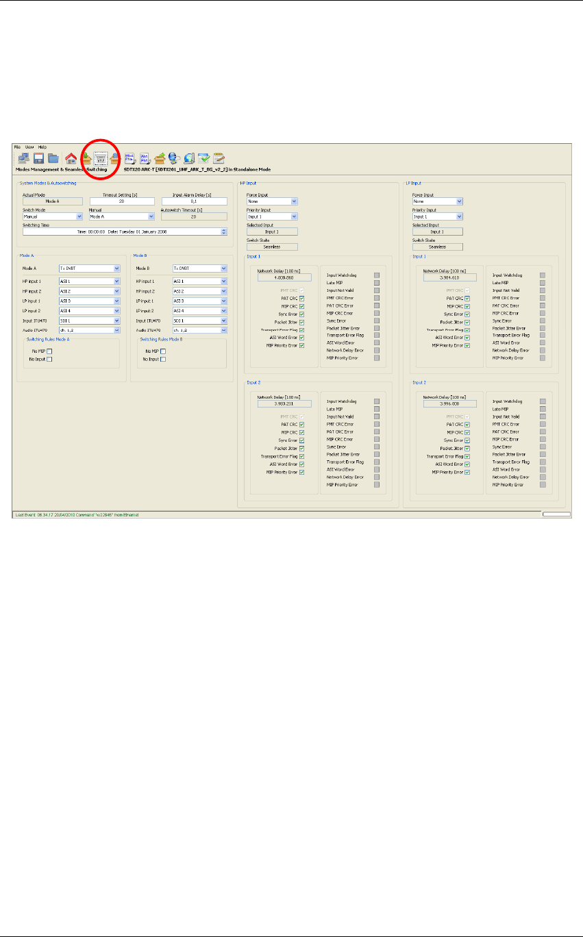
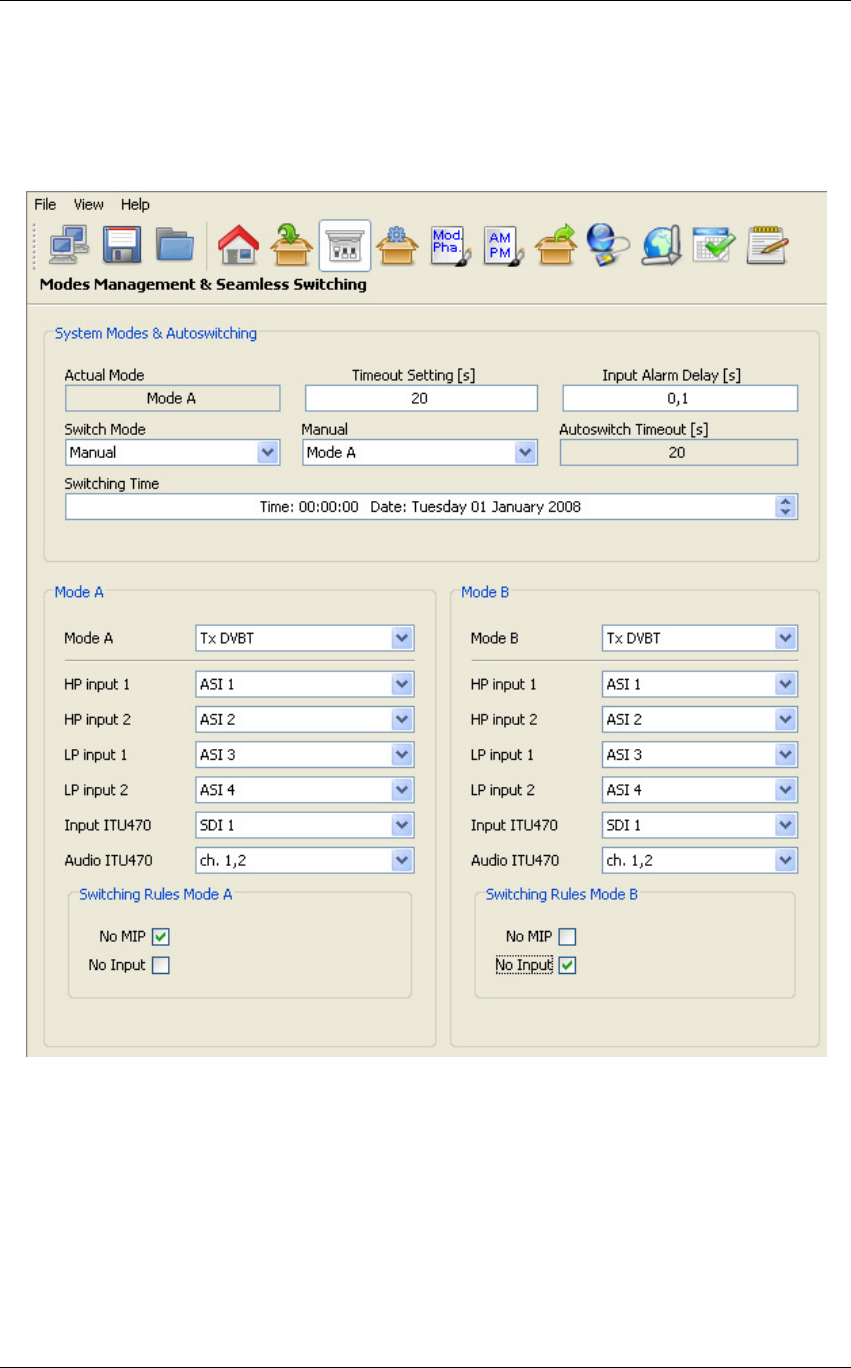
3.4.1.3 Modes management &Seamless Switching
Click on icon, highlighted in the nex figure, to access the tuner window.
Figure 7. Modes Mangement& Seamless Switching
This window provides commands that allow the selection of working modes, the management
and selection of inputs, and the monitoring of quality and level of input RF signals.
The window is divided in the following boxes:
• System Mode & Auto-switching;
• Mode A;
o Switching Rules Mode A;
• Mode B;
o Switching Rules Mode B;
• HP Input;
o Input 1
o Input 2
• LP Input.
o Input 1
o Input 2
Screen Service SDT 501 UB-C ARK 1-T Operations
May, 2010 v 1.0 Page 3 - 28
3.4.2 Modes management
These commands allow the setting of working modes and switch selection rules.
The following table shows the commands and indicators available for modes management.
Figure 8. Modes Management

Screen Service SDT 501 UB-C ARK 1-T Operations
May, 2010 v 1.0 Page 3 - 29
Table 4. Modes management
Box Parameter /
Control Description Admitted Ranges / Values
System Mode &
Auto-switching Actual mode Current operative mode.
• Mode A
• Mode B
System Mode &
Auto-switching Switch mode
Selector of the switch mode rules.
Refer to
Switching modes rules
paragraph for a detailed description of the switching rules and
conditions.
• Manual
• Auto
• Opto
• Time
System Mode &
Auto-switching Manual Selector of used mode when Manual Switch mode is selected.
• Mode A
• Mode B

Screen Service SDT 501 UB-C ARK 1-T Operations
May, 2010 v 1.0 Page 3 - 30
Box Parameter /
Control Description Admitted Ranges / Values
System Mode &
Auto-switching
Timeout
setting
Time to wait for switching. Refer to Switching modes rules paragraph for a detailed description of the
switching rules.
Note: It is highly recommended to set a timeout value different from zero in order to allow the input
signal locking.
• Min: 0 s
• Max: 255 s
System Mode &
Auto-switching
Autoswitch
Timeout
When Auto Switch Mode is enabled shows the time to wait for switching. If the used input regains
lock before the countdown reaches 0 the switch is blocked and device keeps the same mode. • Countdown from 255 to 0
System Mode &
Auto-switching
Input Alarm
Delay [s]
Time to wait for No Input alarm rising (refer to
Alarms
paragraph).
Note 1: It is highly recommended to set an Input Alarm Delay value different from zero in order to
allow the input signal locking.
Note 2: It is highly recommended to set an Input Alarm Delay value not too low (greater than or equal
to 1 second) in order to allow the input seamless switching.
• Min: 0.1 s
• Max: 25.5 s
System Mode &
Auto-switching Switching Time Time and date of modes switching when Time Switch mode is enabled.
Mode A / Mode B Mode A / B Selector of working mode. Only Digital/Analog re-transmitter mode is used by this device.
• Tx DVBT
• Tx Analog (B,G / PAL)

Screen Service SDT 501 UB-C ARK 1-T Operations
May, 2010 v 1.0 Page 3 - 31
Box Parameter /
Control Description Admitted Ranges / Values
Mode A / Mode B HP input 1 Selector of the input1 for re-modulator used for Not Hierarchical Modulation or High Priority.
• ASI 1
• ASI 2
• ASI 3
• ASI 4
• GbE1
• GbE2
Mode A / Mode B HP input 2 Selector of the input2 for re-modulator used for Not Hierarchical Modulation or High Priority.
(this input is ignored in MFN and MFN MIP) •
Mode A / Mode B LP input 1 Selector of the input1 for re-modulator used for Hierarchical Modulation or Low Priority. •
Mode A / Mode B LP input 2 Selector of the input2 for re-modulator used for Hierarchical Modulation or Low Priority.
(this input is ignored in MFN and MFN MIP)

Screen Service SDT 501 UB-C ARK 1-T Operations
May, 2010 v 1.0 Page 3 - 32
Box Parameter /
Control Description Admitted Ranges / Values
Mode A / Mode B Input ITU470 Selector of input ITU470.
• SDI 1
• SDI 2
Mode A / Mode B Audio ITU470 Selector of Audio ITU470.
• ch. 1,2
• ch. 3,4
Switching Rules
Mode A / B
No Input, No
MIP
Auto-switch alarms mask. Refer to
Switching modes rules
paragraph for a detailed description of the
switching rules and conditions.
• Checked: Use rule
• Not checked: Do not use rule

Screen Service SDT 501 UB-C ARK 1-T Operations
May, 2010 v 1.0 Page 3 - 33
3.4.3 Modes switching rules
Four switching rules are provided in order to cover different requirements:
• Manual: switch between mode A and mode B by selecting one mode using the
Manual Selector. The selected mode is always enabled until the user selects the
other one.
• Auto: switch between mode A and mode B using the rules shown in the
following table. One mode is enabled until at least one of the alarms associated
to the enabled automatic switch rules is rising, then a countdown starts and, if
the parameter doesn’t regain a normal status during the timeout, the device
switches to the other mode.
Table 5. Autoswitch rules
Mode Autoswitch rules
TX DVB-T
No Input: selected TS input not locked. No input Alarm should be
enabled in the RF Off alarms mask. It is associated to the
No Input
alarm.
No MIP: MIP packets, in SFN and SFN Local transmission modes, not
present in the selected TS. No MIP Alarm should always be enabled in
the RF Off alarms mask. It is associated to the
DVB-T No MIP
alarm.
Tx Analog
(B,G /
PAL)
No Input: selected SDI input not locked. No input Alarm should be
enabled in the RF Off alarms mask. It is associated to the
No Input
alarm.
• Opto: switch between mode A and mode B by selecting one mode using the
Opto 1 input with the following rules:
o 1 – Open: Mode A.
o 0 – Closed: Mode B.
• Time: switch between mode A and mode B at the specified Date and Time. Switching
will happen only one time from A to B. In order to set the Switching Time, select hours,
minutes, seconds, days, months and years, and click on up/down arrows to
increase/decrease them.
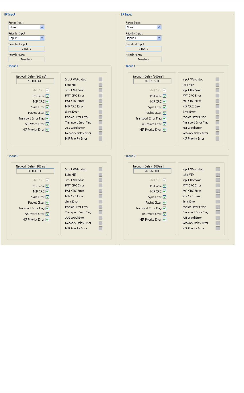
3.4.4 HP/LP INPUT
These commands allow the setting of the seamless parameters and monitoring of the
seamless status for Not Hierarchical Modulation (High Priority) and Hierarchical
Modulation (High Priority and Low Priority).
The following table shows all the commands and indicators available.
following table shows all the commands and indicators available.
Screen Service SDT 501 UB-C ARK 1-T Operations
May, 2010 v 1.0 Page 3 - 34

Screen Service SDT 501 UB-C ARK 1-T Operations
May, 2010 v 1.0 Page 3 - 35
Table 6. Tuner management
Box
Parameter /
Control Description Admitted Ranges / Values
HP Input Force Input
Force input mode. If “None” option is selected, then the device operates the automatic seamless
switching, using the selected priority input if available, and switching to the other input when the priority
input is no more available.
When Force input 1 or 2 is selected, the device works only with the input 1 or 2, and it doesn’t operate
the automatic switching.
• None
• Force Input 1
• Force Input 2
HP Input Priority input
This command allows setting the priority input. Selected priority input shall be the actual used one, until
no error occurs on it. When an error is detected on priority input, device automatically switches to the
other input, and it will come back again to use the priority input when this one shall be available again.
• No priority
• Input 1
• Input 2
HP Input Selected
input It shows the actual logic input used
• Input 1
• Input 2

Screen Service SDT 501 UB-C ARK 1-T Operations
May, 2010 v 1.0 Page 3 - 36
Box Parameter /
Control Description Admitted Ranges / Values
HP Input Switch State
This monitor shows the current device switch state. When both the two inputs are available, the input
seamless switching is possible; else, if only one input is available, then the switching is no more
available. If some error occurs on both inputs, device can’t switch and it can’t use any input.
• Stop
• Input 1 only
• Input 2 only
• Seamless
• Wait
HP Input / Input 1
or Input 2
Network
Delay
[100 ns]
This monitor shows the Network Delay, measured analyzing MIP contained in the input. This delay is
expressed in units of 100 ns.
• Min: 0
• Max: 9999999
HP Input / Input 1
or Input 2
PMT CRC
flag This check isn’t implemented in the actual version.
• Checked: Alarm enabled
• Not checked: Alarm not enabled

Screen Service SDT 501 UB-C ARK 1-T Operations
May, 2010 v 1.0 Page 3 - 37
Box Parameter /
Control Description Admitted Ranges / Values
HP Input / Input 1
or Input 2
PAT CRC
flag
This flag enables the detection of CRC errors in the PAT to force a switching to the other input.
By disabling this rule the detection of a PAT CRC errors doesn’t force the switching of inputs not raises
any alarm.
• Checked: Alarm enabled
• Not checked: Alarm not enabled
HP Input / Input 1
or Input 2
MIP CRC
flag
This flag enables the detection of CRC errors in the MIP to force a switching to the other input.
By disabling this rule the detection of a MIP CRC errors doesn’t force the switching of inputs not raises
any alarm.
• Checked: Alarm enabled
• Not checked: Alarm not enabled
HP Input / Input 1
or Input 2
Sync Error
flag
This flag enables the detection of Sync Error to force a switching to the other input.
By disabling this rule the detection of Sync Error doesn’t force the switching of inputs not raises any
alarm.
• Checked: Alarm enabled
• Not checked: Alarm not enabled
HP Input / Input 1
or Input 2
Packet Jitter
flag
This flag enables the detection of TS packet out of time reception to force a switching to the other input.
By disabling this rule the detection of a packet jitter error doesn’t force the switching of inputs not raises
any alarm.
• Checked: Alarm enabled
• Not checked: Alarm not enabled
HP Input / Input 1
or Input 2
Transport
Error flag
This flag enables the detection of Transport Error flag to force a switching to the other input.
By disabling this rule the detection of a Transport Error flag doesn’t force the switching of inputs not
raises any alarm.
• Checked: Alarm enabled
• Not checked: Alarm not enabled

Screen Service SDT 501 UB-C ARK 1-T Operations
May, 2010 v 1.0 Page 3 - 38
Box Parameter /
Control Description Admitted Ranges / Values
HP Input / Input 1
or Input 2
ASI Word
Error flag
This flag enables the detection of the ASI Word Errors to force a switching to the other input.
By disabling this rule the detection of the ASI Word Errors doesn’t force the switching of inputs not
raises any alarm.
• Checked: Alarm enabled
• Not checked: Alarm not enabled
HP Input / Input 1
or Input 2
MIP Priority
Error flag
This flag enables the check of the MIP priority to force a switching to the other input.
By disabling this rule the detection of the MIP priority Errors doesn’t force the switching of inputs not
raises any alarm.
• Checked: Alarm enabled
• Not checked: Alarm not enabled
HP Input / Input 1
or Input 2
Input
watchdog This alarm is raised when MIP is missing
• Gray: alarm not present or masked
• Red: alarm raised
HP Input / Input 1
or Input 2
Late MIP This alarm is high when the MIP in one of the two seamless inputs of the current mode, is not in its
expected position. This can be caused by a too high delay on the input.
• Gray: alarm not present or masked
• Red: alarm raised
HP Input / Input 1
or Input 2
Input Not
Valid
This alarm is raised when any of the following alarm is raised and is turned off only when the
Input is good enough to allows to work in seamless properly
• Gray: alarm not present or masked
• Red: alarm raised

Screen Service SDT 501 UB-C ARK 1-T Operations
May, 2010 v 1.0 Page 3 - 39
Box Parameter /
Control Description Admitted Ranges / Values
HP Input / Input 1
or Input 2
PMT CRC
Error PMT CRC Error rise this alarm
• Gray: alarm not present or masked
• Red: alarm raised
HP Input / Input 1
or Input 2
PAT CRC
Error PAT CRC Error rise this alarm
• Gray: alarm not present or masked
• Red: alarm raised
HP Input / Input 1
or Input 2
MIP CRC
Error MIP CRC Error rise this alarm
• Gray: alarm not present or masked
• Red: alarm raised
HP Input / Input 1
or Input 2
Sync Error Sync Error rise this alarm
• Gray: alarm not present or masked
• Red: alarm raised
HP Input / Input 1
or Input 2
Packet Jitter
Error Packet Jitter Error rise this alarm
HP Input / Input 1
or Input 2
Transport
Error Flag
Transport Error Flag rise this alarm
HP Input / Input 1
or Input 2
ASI word
Error
ASI word Error rise this alarm
• Gray: alarm not present or masked
• Red: alarm raised

Screen Service SDT 501 UB-C ARK 1-T Operations
May, 2010 v 1.0 Page 3 - 40
Box Parameter /
Control Description Admitted Ranges / Values
HP Input / Input 1
or Input 2
Network
delay Error
This alarm is raised when the TS Network delay is greater than the Maximum delay parameter,
extracted from its MIP
• Gray: alarm not present or masked
• Red: alarm raised
• Gray: alarm not present or masked
• Red: alarm raised
• Gray: alarm not present or masked
• Red: alarm raised
HP Input / Input 1
or Input 2
MIP priority
error This alarm is raised when select a low priority TS as HP input or a High priority TS as LP input
• Gray: alarm not present or masked
•
Red: alarm raise
d
Screen Service SDT 501 UB-C ARK 1-T Operations
May, 2010 v 1.0 Page 3 - 41
3.4.5 MODULATION
Click on Modulation button icon, highlighted in the nex figure, to access the modulation window.
Figure 9. Modulation window: modulation parameters
The Modulation window allows actual modulation parameters monitoring and modulator
setting/monitoring. These settings are always editable but are applied only when the re-
modulator working mode is enabled.
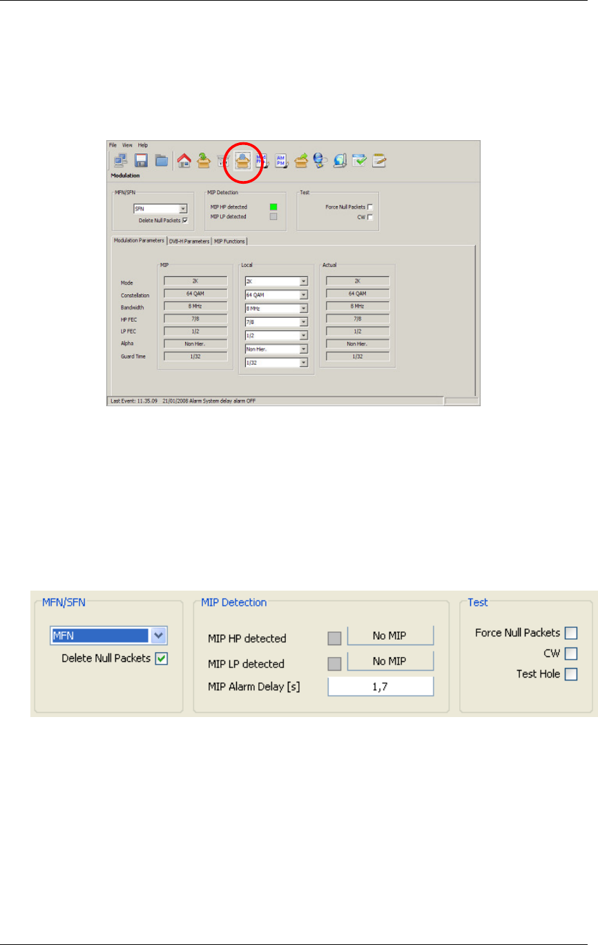
3.4.6 Modulator management
These commands and indicators allow the setting and monitoring of modulator’s synchronization
options, MIP detector and the enabling of Test options.
Figure 10. Modulator management

Screen Service SDT 501 UB-C ARK 1-T Operations
May, 2010 v 1.0 Page 3 - 42
Table 7. Modulation management
Box Parameter/
Control Description Admitted Ranges / Values
MFN / SFN MFN/SFN
Selector of Network’s Transmitters Synchronization.
Refer to
Network Synchronization parameter setting
paragraph.
Note: the seamless
input switching work only in SFN and SFN local,
In MFN and MFN MIP
seamless input switching is disabled and the input is forced to input 1
• MFN
• MFN MIP
• SFN
• SFN Local
MFN / SFN Delete Null
Packets
Delete null packets enabling check box.
In SFN and SFN Local transmission modes, this option is disabled by default and can’t be enabled.
In MFN and MFN MIP transmission modes, this option is enabled by default.
• Checked: Enabled
• Not checked: Disabled
MIP Detection MIP HP/LP
detected Detection of MIP packets in HP/LP streams.
• Green: Detected
• Grey: Not detected

Screen Service SDT 501 UB-C ARK 1-T Operations
May, 2010 v 1.0 Page 3 - 43
Box Parameter/
Control Description Admitted Ranges / Values
MIP Status MIP HP/LP
Status
Show the status of the MIP
Note: the Network delay Error is ? when the TS input (HP or LP) network delay is greater than the MAX
delay written in is MIP
• No MIP
• MIP OK
• Wrong MIP priority
• CRC Error
• Network delay error
MIP Detection MIP Alarm
Delay [s]
Time to wait for No MIP alarm rising expressed in seconds (refer to
Alarms
paragraph).
Note: It is highly recommended to set a MIP Alarm Delay value different from zero as to allow the MIP
detection.
• Min: 1 s
• Max: 25.5 s
Test Force Null
Packets Null data packets transmission enabling check box.
• Checked: Enabled
• Not checked: Disabled

Screen Service SDT 501 UB-C ARK 1-T Operations
May, 2010 v 1.0 Page 3 - 44
Box Parameter/
Control Description Admitted Ranges / Values
Test CW CW test enabling check box.
• Checked: Enabled
• Not checked: Disabled

Screen Service SDT 501 UB-C ARK 1-T Operations
May, 2010 v 1.0 Page 3 - 45
3.4.7 Network Synchronization parameters setting
Four Network Synchronization modes are available:
• Multi Frequency Network mode using local parameters (MFN):
The transmitter is not synchronized with any network. No input MIP is
needed and Clock Reference can be internal.
• Multi Frequency Network mode using MIP parameters (MFN MIP):
The transmitter is not synchronized with any network but MIP sets the
modulation parameters. Input MIP is needed and Clock Reference can
be internal.
• Single Frequency Network mode (SFN): The transmitter is
synchronized with a Network of transmitters on the same frequency.
MIP is needed and Clock Reference must be external or GPS.
• Single Frequency Network mode using local parameters (SFN
Local): The transmitter is synchronized with a Network of transmitters
but for testing purposes the modulation parameters are set locally.
Input MIP is needed for 1PPS synchronization and Clock Reference
must be external or GPS.
The following table provides a description of the available parameters setting
for the network modes.
Table 8. Network Synchronization parameters setting
Parameters MFN SFN MFN + MIP SFN Local
Mode Local MIP MIP Local
Constellation Local MIP MIP Local
FEC HP Local MIP MIP Local
FEC LP Local MIP MIP Local
Transmission Local MIP MIP Local
Time Slicing
HP Local MIP MIP Local
Time Slicing
LP Local MIP MIP Local
Guard Time Local MIP MIP Local
BW Local MIP MIP Local
Alpha Local MIP MIP Local
Input HP Local Local Local Local
Input LP Local Local Local Local
Interleaver Local (for 8k
mode only native) MIP MIP
Local (for 8k
mode only
native)
MPE FEC HP Local MIP MIP Local
MPE FEC LP Local MIP MIP Local
Cell Id enable Local Local Local Local
Cell Id Local (only if
enabled)
MIP or Local
(only if enabled)
Function from MIP
can be enabled or
disabled
MIP or Local
(only if enabled)
Function from MIP
can be enabled or
disabled
Local (only if
enabled)
Frequency
Offset Local
MIP or Local
(only if enabled)
Function from MIP
can be enabled or
disabled
MIP or Local
(only if enabled)
Function from MIP
can be enabled or
disabled
Local
Screen Service SDT 501 UB-C ARK 1-T Operations
May, 2010 v 1.0 Page 3 - 46
Parameters MFN SFN MFN + MIP SFN Local
Time Offset Local
MIP or Local
(only if enabled)
Function from MIP
can be enabled or
disabled
MIP or Local
(only if enabled)
Function from MIP
can be enabled or
disabled
Local
Del Null
Packet
Can be enabled or
disabled Must be disabled Can be enabled or
disabled
Must be
disabled
Frequency
Reference
Can be internal or
external Must be external Can be internal or
external
Must be
external
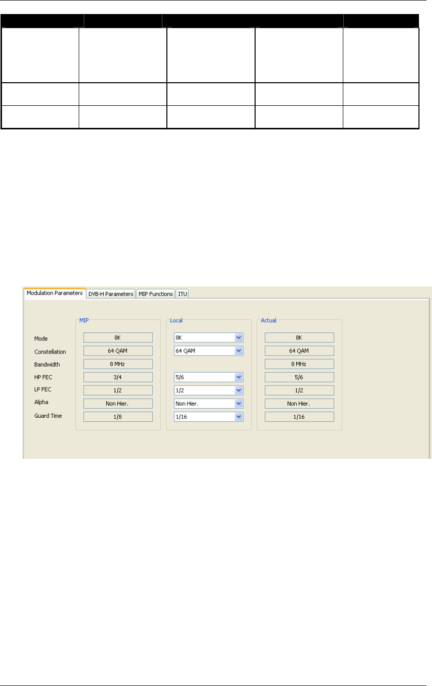
3.4.8 Modulation parameters
These commands and indicators allow the setting of modulation parameters.
This includes the monitoring of parameters carried by MIP in SFN configuration
and of actual modulation parameters for Digital Re-transmitter mode.
Note: ARK-T read only the modulation parameters of HP input MIP
Figure 11. Modulation parameters

Screen Service SDT 501 UB-C ARK 1-T Operations
May, 2010 v 1.0 Page 3 - 47
Table 9. Modulation parameters
Box
Parameter/
Control Description Admitted Ranges / Values
MIP Transmission mode: set by MIP.
Local
Transmission mode: locally set.
Actual
Mode
Current transmission mode
• 2K
• 4K
• 8K
MIP Constellation Constellation for current modulation scheme: set by MIP.
• QPSK
• 16-QAM
• 64-QAM
Local Constellation for current modulation scheme: locally set. •
Actual Current constellation for modulation scheme.
MIP
Bandwidth Bandwidth: set by MIP.
•

Screen Service SDT 501 UB-C ARK 1-T Operations
May, 2010 v 1.0 Page 3 - 48
Box Parameter/
Control Description Admitted Ranges / Values
Actual
Current bandwidth.
MIP HP/LP stream code rate: set by MIP.
Local
HP/LP stream code rate: locally set.
Actual
HP/LP FEC
Current HP/LP stream code rate.
• 1/2
• 2/3
• 3/4
• 5/6
• 7/8
MIP Hierarchy information for current scheme: set by MIP.
Local
Hierarchy information for current scheme: locally set.
Actual
Alpha
Current Hierarchy information for current scheme.
• NH;
• a=1;
• a=2;
• a=4.
MIP Guard interval: set by MIP.
Guard Time
• 1/32

Screen Service SDT 501 UB-C ARK 1-T Operations
May, 2010 v 1.0 Page 3 - 49
Box Parameter/
Control Description Admitted Ranges / Values
Screen Service SDT 501 UB-C ARK 1-T Operations
May, 2010 v 1.0 Page 3 - 50
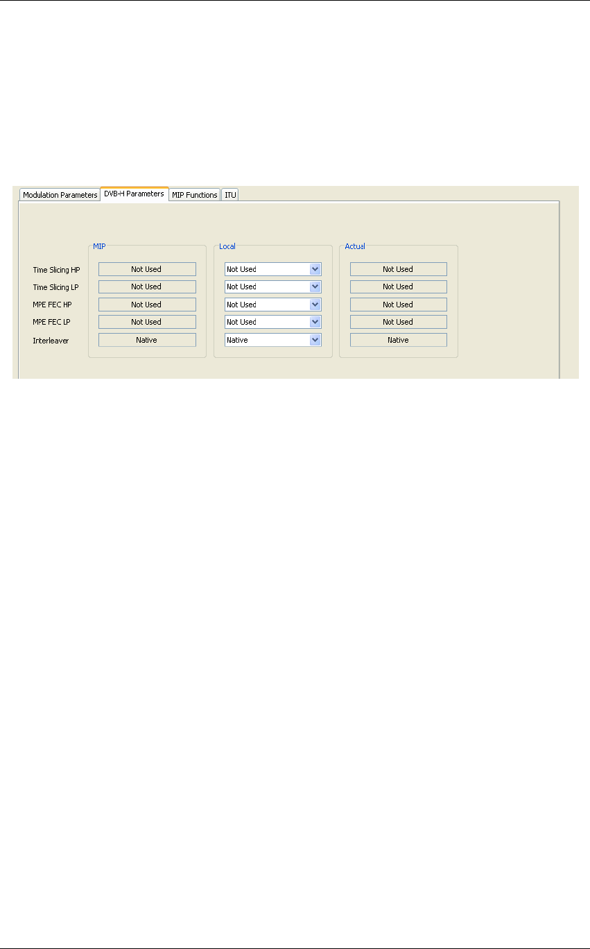
3.4.9 DVB-H parameters
These commands and indicators allow the setting of options for DVB-H transmission, the
monitoring of parameters carried by MIP in SFN configuration and of actual DVB-H options.
Note: ARK-T read only the DVB-H parameters of HP input MIP
Figure 12. DVB-H parameters

Screen Service SDT 501 UB-C ARK 1-T Operations
May, 2010 v 1.0 Page 3 - 51
Table 10.
DVB-H parameters.
Box
Parameter/
Control Description Admitted Ranges / Values
MIP Enabling of time slice transmission of the HP/LP stream: set by MIP.
Local Enabling of time slice transmission of the HP/LP stream: locally set.
Actual
Time Slicing
HP/LP
Current enabling status of time slice transmission.
• Used
• Not used
MIP HP/LP MPE-FEC enabling: set by MIP.
Local HP/LP MPE-FEC enabling: locally set.
Actual
MPE FEC
HP/LP
Current HP/LP MPE-FEC enabling status.
• Used
• Not used
MIP Interleaver type selector: set by MIP.
Local Interleaver type selector: locally set.
Actual
Interleaver
Interleaver type selector status.
• Used
• Not used
Screen Service SDT 501 UB-C ARK 1-T Operations
May, 2010 v 1.0 Page 3 - 52
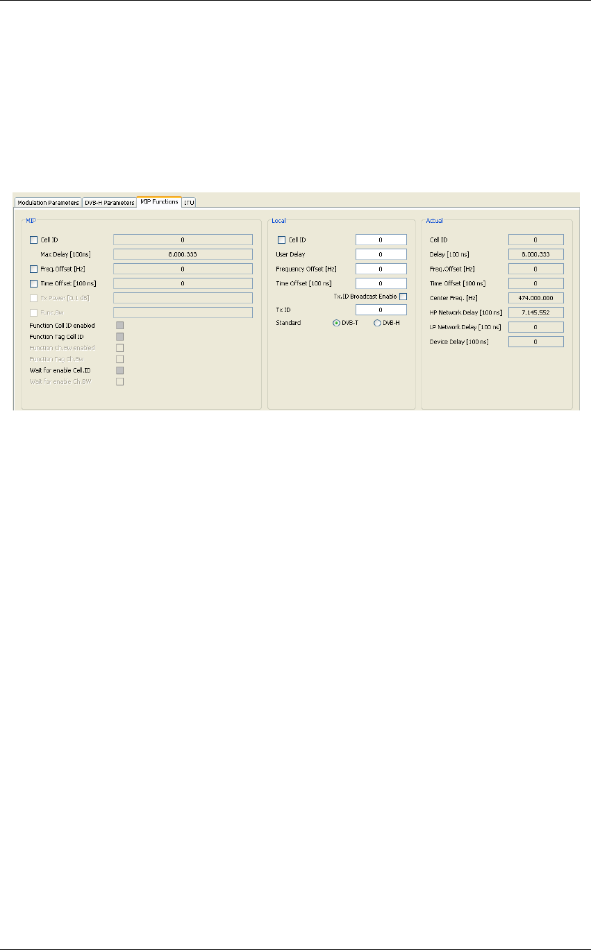
3.4.10 MIP functions
These commands and indicators allow the enabling and monitoring of MIP functions
in SFN configuration, the setting of local functions and the monitoring of the actual
functions used by modulator.
Note: ARK-T read only the function of HP input MIP
Figure 13. MIP functions

Screen Service SDT 501 UB-C ARK 1-T Operations
May, 2010 v 1.0 Page 3 - 53
Box Parameter /
Control Description Admitted Ranges / Values
MIP MIP cell ID function enabling
Local
Cell Id enable
General Cell Id enabling. Must be enabled to insert Cell Id into output TPS.
• Checked: Enabled
• Not checked: Disabled
MIP MIP cell ID monitoring.
Local Local Cell ID setting.
• Min: 0
• Max: 65,535
Actual
Cell ID
Used Cell ID monitoring.
MIP Max Delay
[100ns] MIP max delay function monitoring
Local User Delay User delay setting.
This value is added to the MIP max delay to calculate the Used delay
• Min: - 8388608
• Max: 8388607
Actual Delay [100ns]
Used delay monitoring.
In SFN this value is calculated adding the MIP max delay, the Local user delay, the MIP Time offset, the
Local time offset and the Device delay
In MFN this value is calculated adding the Local user delay and the Device delay
Note: this value must be greater than the HP and LP network delay
• Min: 0
• Max: 9,999,999

Screen Service SDT 501 UB-C ARK 1-T Operations
May, 2010 v 1.0 Page 3 - 54
Box Parameter /
Control Description Admitted Ranges / Values
MIP MIP frequency offset function enabling and monitoring
• Checked: Enabled
• Not checked: Disabled
Local User frequency offset setting.
• Min: –500,000 Hz
• Max: 500,000 Hz
Actual
Freq. Offset [Hz]
Used frequency offset monitoring.
MIP MIP time offset function enabling and monitoring
In SFN This value is added to the MIP max delay to calculate the Used delay
• Checked: Enabled
• Not checked: Disabled
Local User time offset setting.
In SFN This value is added to the MIP max delay to calculate the Used delay
• Min: –32,768
• Max: 32,767
Actual
Time Offset
[100ns]
Used time offset monitoring.

Screen Service SDT 501 UB-C ARK 1-T Operations
May, 2010 v 1.0 Page 3 - 55
Box Parameter /
Control Description Admitted Ranges / Values
MIP Tx Power [0.1dB] NOT IMPLEMENTED (MIP Tx power function enabling and monitoring).
• Checked: Enabled
• Not checked: Disabled
MIP Func.Bw NOT IMPLEMENTED (Function Bw enabling and monitoring).
• Checked: Enabled
• Not checked: Disabled
MIP Function Cell ID
enabled MIP Cell ID function enabling status.
• Green: enabled
• Grey: disabled
MIP Function Tag Cell
ID. Cell ID Tag detection.
• Green: present
• Grey: not present
MIP Function Ch.Bw
enabled NOT IMPLEMENTED (MIP channel bandwidth function enabling status).
• Green: enabled
• Grey: disabled

Screen Service SDT 501 UB-C ARK 1-T Operations
May, 2010 v 1.0 Page 3 - 56
Box Parameter /
Control Description Admitted Ranges / Values
MIP Function Tag
Ch.Bw NOT IMPLEMENTED (Cannel bandwidth Tag detection).
• Green: present
• Grey: not present
MIP Wait for enable
Cell ID
It displays if the cell ID has to be inserted immediately (Grey) or after the receiving of the broadcasting
enable.
• Green: present
• Grey: not present
MIP Wait for enable
Ch.Bw NOT IMPLEMENTED (Not implemented in the actual version).
Local Tx ID Broadcast
Enable Tx ID 0 enabling.
• Checked: Enabled
• Not checked: Disabled
Local Tx ID User Tx ID setting.
• Min: 0
• Max: 65,535

Screen Service SDT 501 UB-C ARK 1-T Operations
May, 2010 v 1.0 Page 3 - 57
Box Parameter /
Control Description Admitted Ranges / Values
Local Standard User transmission standard setting.
• DVB-T
o Checked: Enabled
o Not checked:
Disabled
• DVB-H
o Checked: Enabled
o Not checked:
Disabled
Actual Center Freq. [Hz] Used center frequency indicator.
Actual HP Network Delay
[100ns] Used HP input network delay indicator.
Actual
LP Network Delay
[100ns] Used LP input network delay indicator.

Screen Service SDT 501 UB-C ARK 1-T Operations
May, 2010 v 1.0 Page 3 - 58
Box Parameter /
Control Description Admitted Ranges / Values
Actual
Device Delay
[100ns]
Default device delay monitoring.
This value is added to the MIP max delay to calculate the Used delay
• Min: - 8388608
• Max: 8388607
Table 11.
MIP functions
Screen Service SDT 501 UB-C ARK 1-T Operations
May, 2010 v 1.0 Page 3 - 59
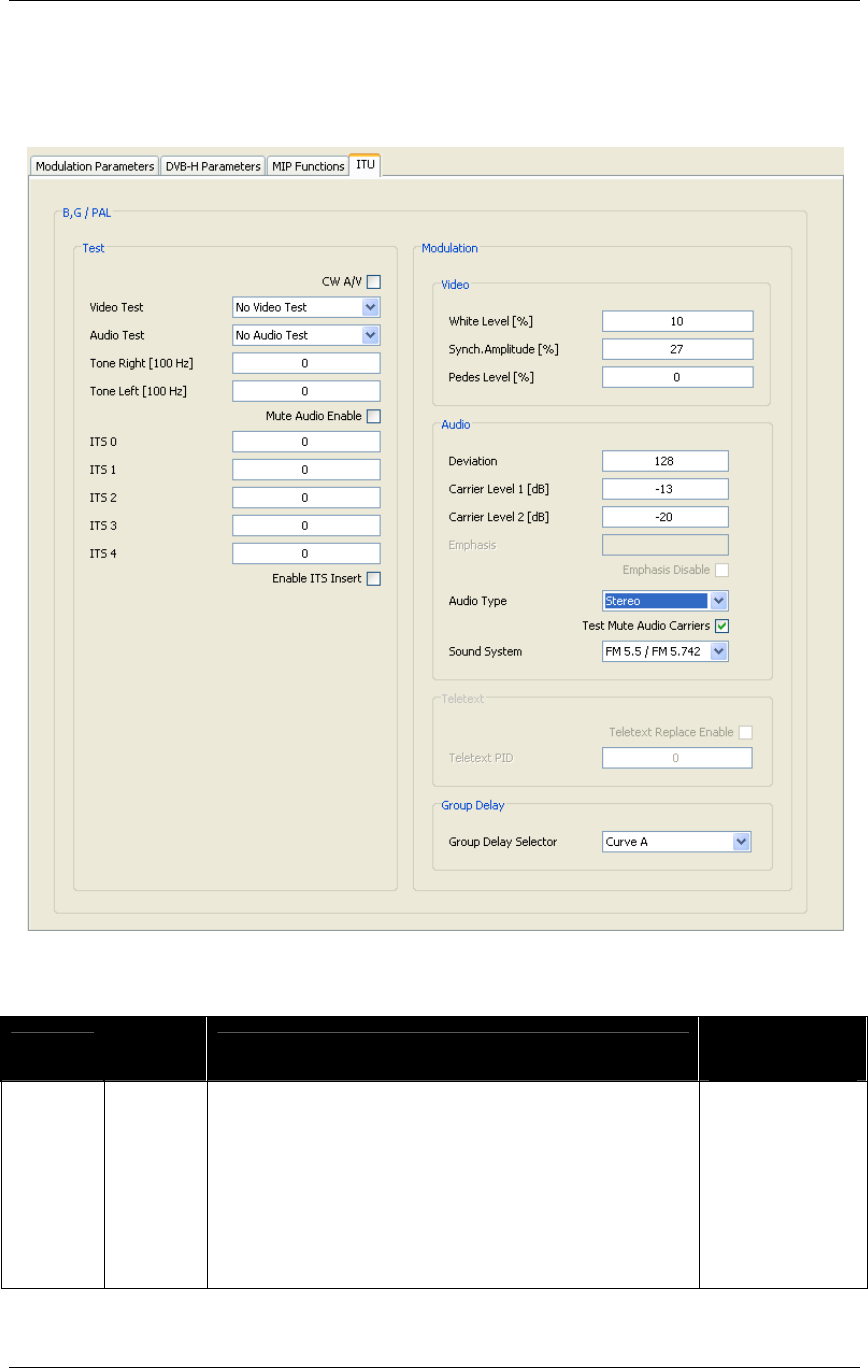
3.4.11 ITU functions
These commands and indicators allow the enabling and monitoring of ITU functions.
Figure 14. ITU functions
Box Parameter
/ Control Description Admitted Ranges
/ Values
Test CW A/V Enable for CW on video and audio carriers.
•
Checked:
Enabled
•
Not checked:
Disabled

Screen Service SDT 501 UB-C ARK 1-T Operations
May, 2010 v 1.0 Page 3 - 60
Box Parameter
/ Control Description Admitted Ranges
/ Values
Test
Video Test Video test color bars enable.
•
Bars
•
No Video Test
Test
Audio Test Audio test tones enable.
•
No Video Test
•
Audio Tone
Test
Tone Right
[100 Hz] Right tone frequency setting.
•
Min: 0
•
Max: 127
Test
Tone Left
[100 Hz] Left tone frequency setting.
•
Min: 0
•
Max: 127
Test
Mute
Audio
Enable
Audio mute enable
•
Checked:
Enabled
•
Not checked:
Disabled
Test
ITS 0 Position of fixed line number 0 in output video.
•
Min: 7
•
Max: 622
Test
ITS 1 Position of fixed line number 1 in output video.
•
Min: 7
•
Max: 622
Test
ITS 2 Position of fixed line number 2 in output video.
•
Min: 7
•
Max: 622

Screen Service SDT 501 UB-C ARK 1-T Operations
May, 2010 v 1.0 Page 3 - 61
Box Parameter
/ Control Description Admitted Ranges
/ Values
Test
ITS 3 Position of fixed line number 3 in output video.
•
Min: 7
•
Max: 622
Test
ITS 4 Position of fixed line number 4 in output video.
•
Min: 7
•
Max: 622
Test
Enable
ITS Insert Enable fixed lines insertion in output video.
•
Checked:
Enabled
•
Not checked:
Disabled
Modulation
/ Video
White
Level [%]
Video white level setting. The level value is in percentage upon
the synch level. The synch level is taken as 100% reference.
•
MIN: 10
•
MAX: 22
•
Step: 0,05
Modulation
/ Video
Synch.
Amplitude
[%]
Video synch amplitude setting. The level value is in
percentage upon the synch level. The synch level is taken as
100% reference.
•
MIN: 22
•
MAX: 27,5
•
Step: 0,05
Modulation
/ Video
Pedes
Level [%]
Video pedes level setting. The level value is in percentage
upon the synch level. The synch level is taken as 100%
reference.
•
MIN: 0
•
MAX: 7
•
Step: 0,05

Screen Service SDT 501 UB-C ARK 1-T Operations
May, 2010 v 1.0 Page 3 - 62
Box Parameter
/ Control Description Admitted Ranges
/ Values
Modulation
/ Audio Deviation Audio deviation.
•
Min: 0
•
Max: 255
Modulation
/ Audio
Carrier
Level 1
[dB]
Audio 1 carrier level setting.
•
MIN: –7
•
MAX: –22
•
Step: 0,1
Modulation
/ Audio
Carrier
Level 2
[dB]
Audio 2 carrier level setting. Not used for NTSC
•
MIN: –7
•
MAX: -–22
•
Step: 0,1
Modulation
/ Audio Emphasis Audio emphasis value monitor.
Modulation
/ Audio
Emphasis
disable Disable Audio emphasis
Modulation
/ Audio
Audio
Type
Audio type selector. Only the mono single carrier audio
type is used for NTSC.
•
Mono Dual
Carrier
•
Dual Sound
•
Stereo
•
Mono Single
Carrier
Modulation
/ Audio
Test Mute
Audio
Carriers
Remove the audio carrier.
•
Checked:
Enabled
•
Not checked:
Disabled

Screen Service SDT 501 UB-C ARK 1-T Operations
May, 2010 v 1.0 Page 3 - 63
Box Parameter
/ Control Description Admitted Ranges
/ Values
Modulation
/ Audio
Sound
System Set the position of the two audio carriers.
PAL B, G
•
FM 5.5 / FM
5.742
PAL D, K
•
FM 6.5 / FM
6.742
•
FM 5.5 / FM
6.258
Modulation
/ Teletex
Teletex
Replace
Enable
Replace enable for teletext. It is contained in elementary
stream with above-specified PID.
•
Not checked:
teletext not
replaced
•
Checked:
teletext
replaced
Modulation
/ Teletex
Teletex
PID PID of elementary stream containing teletext.
•
Min: 0
•
Max: 8191
Modulation
/ Group
Delay
Group
Delay
Selector
Command for Group Delay Filter.
•
Flat
•
Curve A
•
Curve B
Screen Service SDT 501 UB-C ARK 1-T Operations
May, 2010 v 1.0 Page 3 - 64
3.5 PRE-CORRECTION TOOL
The ARK1-T system provides a pre-correction tool for both Module & Phase and AM/PM output
signal pre-correction.
Remember to click on the Save as button the first time you change the factory default curves in
order to do not overwrite them.
Before closing the connection to port 5000, save curves changes otherwise they will be lost.
Note: the operation of uploading and downloading pre-correction curves moves a large amount
of data from and to the device. The use of these tools over low bandwidth, not stable or high
distances networks could cause frequently time-out disconnections and it is not recommended.
In order to correctly visualize Module & Phase and AM/PM windows of the GUI, the minimum
required screen resolution is 1280 by 960 pixels. For lower screen resolutions, from 1024 per
768 pixels to 1280 by 800 pixels, use either the F11 function, Full Screen option, or download
the standalone java application (executable *.jar file) through the Download Software
Standalone button sited in the General window.
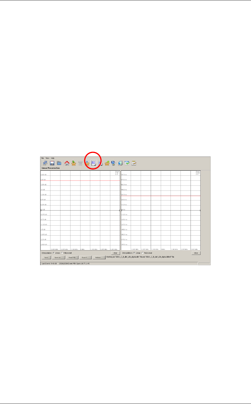
3.5.1 Module&Phase
Click on MOD. PHA. button icon, highlighted in the nex figure, to modify the complex filter curves
for linear pre-correction.
Figure 15. Phase and module window
This tool provides two grids for the drawing of:
• Module of the filter’s curve.
• Group Delay of the filter’s curve.
The two curves are used to calculate the linear pre-correction coefficients. The curves are drawn
by the interpolation of 1024 points referring to the points inserted and using a linear or
polynomial interpolation algorithm.
Knob points can be added with a left-click of the mouse on the grid and deleted with a right-click,
drag and move a point to change the curve.
Each coefficient variation, due to curves change, is saved in the FPGA “runtime” memory
registers and dynamically changes the device’s output.
The tool is prevented to send an “overflowing” amount of data to the device: curve changes will
be applied only when the mouse button is released.
In the module grid, the red curve is used to monitor the current module curve calculating and
saving. The last saved coefficients are locally downloaded from the FPGA runtime memory
registers in order to redraw the curve.
Screen Service SDT 501 UB-C ARK 1-T Operations
May, 2010 v 1.0 Page 3 - 65
Click two times the right mouse button on the grid to open the zoom menu. The “H” options are
used to horizontally zoom (x01,x02,x04,x08,x16). The “V” options are used to vertically zoom
(x01,x02,x04).
During the saving actions are created two nonlinear pre-correction files:
• *.dlin files: files containing digital coefficients values for Digital-IF linear pre-correction
curves.
• *.alin files: files containing analog coefficients values for DVB-T Re-modulator linear pre-
correction curves.
The following buttons allow the management of linear pre-correction files and the management
of the connection to port 5000:
• Save: used to save in the device memory the current curves setting. The previously
saved file will be overwritten except in the evet that no files have been saved before; in
this case a dedicated window appears in order to let the user name the new file.
• Save as: used to save in the device memory the current curves setting. The previously
saved file will be overwritten with a new name. in the evet that no files have been saved
before, a new file will be created.
• Read file: used to reload the last saved file.
• Export: used to download pre-correction files on the user PC. A browser window allows
the selection of the saving path.
• Release: release the connection in order to allow others remote machines to connect to
port 5000 (refer to Connection to port 5000 paragraph).
Files are separately managed in analog and in digital AGC mode.
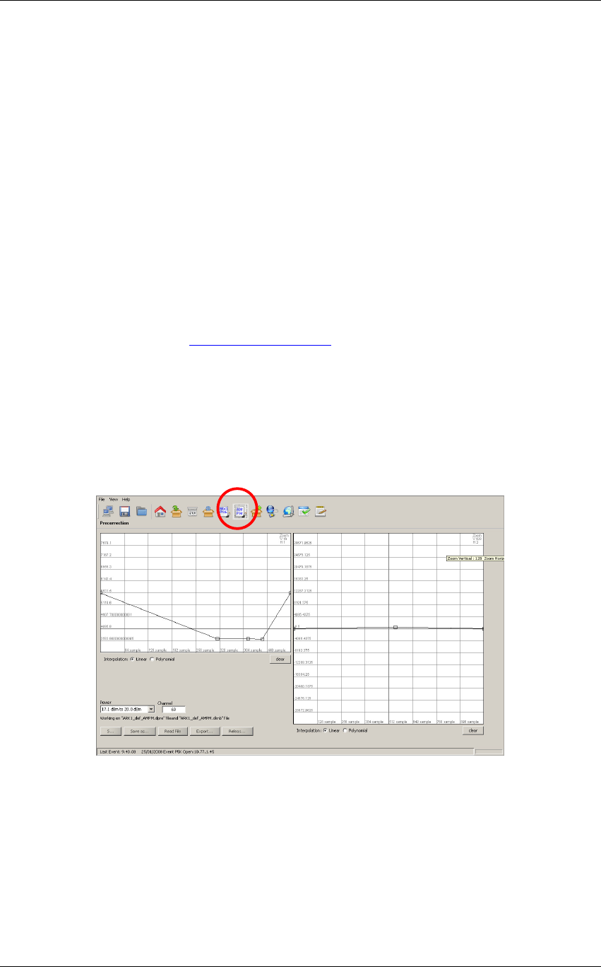
3.5.2 AM/PM
Click on AM/PM button icon, highlighted in the nex figure, to access the pre-correction window.
Figure 16. AM/PM window
Two main actions are possible in this section:
• AM/AM and AM/PM curve drawing: used to change the AM/PM pre-correction
coefficient.
• AM/PM pre-correction files management: used to open or save AM/PM pre-correction
setting file.
AM/AM and AM/PM curves are specific for each power range of each output channel.
The two curves are used to calculate the AM/PM pre-correction coefficients. The curves are
drawn by the interpolation of 1024 points referring to the points inserted and using a linear or
polynomial interpolation algorithm.

Screen Service SDT 501 UB-C ARK 1-T Operations
May, 2010 v 1.0 Page 3 - 66
Knob points can be added with a left-click of the mouse on the grid and deleted with a right-click,
drag and move a point to change the curve.
Each coefficient variation, due to curves change, is saved in the FPGA “runtime” memory
registers and dynamically changes the device’s output.
The tool is prevented to send an “overflowing” amount of data to the device: curve changes will
be applied only when the mouse button is released.
In the module grid, the red curve is used to monitor the current module curve calculating and
saving. The last saved coefficients are locally downloaded from the FPGA runtime memory
registers in order to redraw the curve.
Click two times the right mouse button on the grid to open the zoom menu. The “H” options are
used to horizontally zoom (x01,x02,x04,x08,x16). The “V” options are used to vertically zoom
(x01,x02,x04).
During saving actions are created two nonlinear pre-correction files:
• *.dpre files: files containing digital coefficients values.
• *.apre files: files containing analog coefficients values.
The following buttons allow the management of linear pre-correction files and the management
of the connection to port 5000:
• Save: used to save in the device memory the current curves setting. The previously
saved file will be overwritten except in the evet that no files have been saved before; in
this case a dedicated window appears in order to let the user name the new file.
• Save as: used to save in the device memory the current curves setting. The previously
saved file will be overwritten with a new name. in the evet that no files have been saved
before, a new file will be created.
• Read file: used to reload the last saved file.
• Export: used to download pre-correction files on the user PC. A browser window allows
the selection of the saving path.
• Release: release the connection in order to allow others remote machines to connect to
port 5000 (refer to Connection to port 5000 paragraph).
Files are separately managed in analog and in digital AGC mode.
Screen Service SDT 501 UB-C ARK 1-T Operations
May, 2010 v 1.0 Page 3 - 67
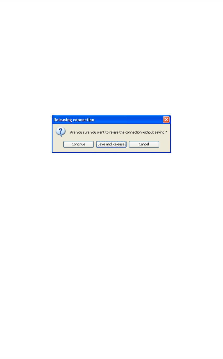
3.5.3 Connection to port 5000
The connection to port 5000 is performed every time a pre-correction tool is opened through
Mod.Pha. button and AM/PM button, from Java interface,. The pre-correction tool opens and
keeps busy the connection to port 5000 till the connection releasing
The connection to this port precludes the possibility of:
• programming the device;
• allowing more than one user, the very same one that is keeping busy the connection, to
open the pre-correction tools.
The Release button comes through these limits. It closes the connection to port 5000, close the
Mod.Pha. / AM/PM window and opens the General window. Once clicked the Release buttons
and before quitting the pre-correction tool, three options are provided:
• Continue: continue without saving;
• Save and Release: save and continue;
• Cancel: cancel the request of releasing the connection.
Figure 17. Realising connection
Screen Service SDT 501 UB-C ARK 1-T Operations
May, 2010 v 1.0 Page 3 - 68
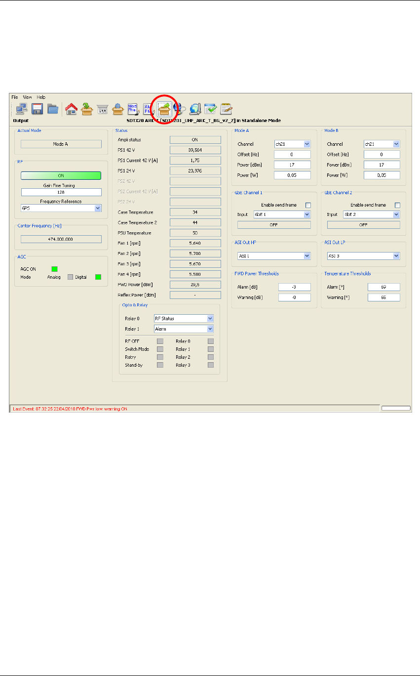
3.5.4 OUTPUT
Click on Output button icon, highlighted in the nex figure, to access the output window.
Figure 18. Output window
Use the Output window to change Ethernet, RF output and ASI output settings, and to monitor
all available hardware indicators.
Differently from ARK1 and ARK1-R devices, the ASI outputs are here used as a direct bypass of
the specified inputs.

Screen Service SDT 501 UB-C ARK 1-T Operations
May, 2010 v 1.0 Page 3 - 69
Output window
Box
Parameter /
Control Description Admitted Ranges / Values
RF ON / OFF
Output RF signal enabling. The possible output RF signal status are the following:
•
ON;
•
RF OFF: automatic switch off of the output signal (refer to Amplifier status);
•
OFF: manual switch off of the output signal.
•
Green: ON
•
Green: RF OFF
•
Red: OFF
RF Frequency
reference
Frequency reference source selector. This command will select the reference source used to lock the
internal clocks (10 MHz and 1 PPS). When set to internal the 10 MHz clock and 1 PPS generator runs
unlocked. When set to external or GPS the 10 MHz clock is locked to the source selected and the 1
PPS counter reset is triggered by the source 1 PPS.
Note: External 10 MHz, 1PPS and GPS shall be connected and locked when the External and GPS are
selected as frequency references.
•
External
•
Internal
•
GPS

Screen Service SDT 501 UB-C ARK 1-T Operations
May, 2010 v 1.0 Page 3 - 70
Box Parameter /
Control Description Admitted Ranges / Values
RF Internal Freq.
Ref. Tune
Internal frequency reference fine tuning setting. Allows the fine tuning of VCO, internal clock oscillator,
with 60 Hz steps.
•
Min: 0
•
Max: 255
AGC AGC ON AGC status.
•
Green: ON
•
Grey: OFF
AGC Mode Current AGC mode indicator. It is always digital.
•
Analog/Digital:
o Green: ON
o Grey: OFF
Frequency
Out [Hz]
Frequency
Out [Hz] Shows the output center frequency expressed in Hz.

Screen Service SDT 501 UB-C ARK 1-T Operations
May, 2010 v 1.0 Page 3 - 71
Box Parameter /
Control Description Admitted Ranges / Values
Status Ampli status Current amplifier status indicator.
•
On
•
Off
•
Restart
•
Stand-by off
•
GPS Off
•
Init
•
Alarm off
•
Rf off
•
Opto off
•
Change mode
•
Interlock ON

Screen Service SDT 501 UB-C ARK 1-T Operations
May, 2010 v 1.0 Page 3 - 72
Box Parameter /
Control Description Admitted Ranges / Values
Status PS1 28V / 42V
First PSU voltage indicator (values are expressed in V). It depends on the hardware type of the device:
•
28V for SDTx 20 and SDTx 50;
•
42V for SDTx 201 and SDTx 501;
Status PS1 Current
28V / 42V [A]
First PSU current indicator (values are expressed in A) It depends on the hardware type of the device:
•
28V for SDTx 20 and SDTx 50;
•
42V for SDTx 201 and SDTx 501;
Status PS1 24V First PSU 24V indicator (values are expressed in V).
Only in SDTX 201 and SDTX 501 version.
Status PS2 42V Second PSU voltage indicator (values are expressed in V).
Only in SDTX 501 version.
Status PS2 Current 42V
[A]
Second PSU current indicator (values are expressed in A)
Only in SDTX 501 version.
Status PS2 24V Second PSU 24V indicator (values are expressed in V).
Only in SDTX 501 version.
Status Case
Temperature Case temperature indicator (values are expressed in °C).
Status Case
Temperature 2
2
nd
Case temperature indicator (values are expressed in °C).
Only in SDTX 200 version.

Screen Service SDT 501 UB-C ARK 1-T Operations
May, 2010 v 1.0 Page 3 - 73
Box Parameter /
Control Description Admitted Ranges / Values
Status PSU
Temperature PSU temperature indicator (values are expressed in °C).
Status Fan 1 Fan 1 speed indicator (values are expressed in rpm).
Used in SDTX20, SDTX50 and SDTX201
Status Fan 2 Fan 2 speed indicator (values are expressed in rpm).
Used in SDTX20, SDTX50 SDTX201, and SDTX501
Status Fan 3 Fan 3 speed indicator (values are expressed in rpm).
Used in SDTX201, and SDTX501
Status Fan 4 Fan 4 speed indicator (values are expressed in rpm).
Used in SDTX201, and SDTX501
Status FWD Power
[dBm] Output forward power indicator (values are expressed in dBm).
Status Reflex Power
[dBm] Output reflex power indicator (values are expressed in dBm).

Screen Service SDT 501 UB-C ARK 1-T Operations
May, 2010 v 1.0 Page 3 - 74
Box Parameter /
Control Description Admitted Ranges / Values
Opto & Relay Relay 0 Selector of Relay 0 mode.
•
Alarm: indicator of an alarm
condition
•
Mode: indicator of operating mode
•
RF Status: indicator output RF
signal status (on/off)
Opto & Relay Relay 1 Selector of Relay 1 mode.
•
Alarm: indicator of an alarm
condition
•
Mode: indicator of operating mode
Opto & Relay Relay 0…3 Relays status indicators.
•
Green: Alarm on/Mode A/RF Off
•
Grey: Alarm off/Mode B/RF On

Screen Service SDT 501 UB-C ARK 1-T Operations
May, 2010 v 1.0 Page 3 - 75
Box Parameter /
Control Description Admitted Ranges / Values
Opto&Relay
Opto 0
RF Off Opto status indicators.
Opto 0 is a output RF manual on/off switch:
•
Closed (0): RF on (default value)
•
Opened (1): RF off
•
Green: Closed (0)
•
Grey: Opened (1)
Opto&Relay
Opto 1
Switch mode Opto status indicators.
When the Switch mode is set to Opto:
•
Closed (0): Switch to mode B
•
Opened (1): Switch to mode A
•
Green: Closed (0)
•
Grey: Opened (1)
Opto&Relay
Opto 2 Retry of amplifier alarms status indicators.(only in SDTX 201 version);
•
Green: Closed (0)
•
Grey: Opened (1)

Screen Service SDT 501 UB-C ARK 1-T Operations
May, 2010 v 1.0 Page 3 - 76
Box Parameter /
Control Description Admitted Ranges / Values
Opto&Relay Opto 3
Stand-by enabling Opto status indicators: .( in version SDTX 20/50/201);
•
Closed (0): stand-by off
•
Opened (1): stand-by on
Interlock Opto status indicators.(only in SDTX 501 version);
•
Closed (0): Interlock off
•
Opened (1): Interlock on
•
Green: Closed (0)
•
Grey: Opened (1)
Mode A / Mode B Channel Output channel. Channel ranges are device’s definition
dependant.
Mode A / Mode B Power [dBm] Output power (expressed in dBm).
Mode A / Mode B Power [W] Output power (expressed in W).
Output power ranges are device’s
definition dependant.
Refer to Appendix C

Screen Service SDT 501 UB-C ARK 1-T Operations
May, 2010 v 1.0 Page 3 - 77
Box Parameter /
Control Description Admitted Ranges / Values
Mode A / Mode B Offset [Hz] Output frequency offset (expressed in Hz).
•
Min: -4 MHz
•
Max: 4 MHz
FWD Power
Thresholds Warning [dB] Forward power warning threshold expressed in dBm.
FWD Power
Thresholds Alarm [dB] Forward power alarm threshold expressed in dBm.
•
Min: -16 dBm
•
Max: 0 dBm
Temperature
Thresholds Warning Case temperature warning threshold expressed in °C.
Temperature
Thresholds Alarm Case temperature alarm threshold expressed in °C.
•
Min: 0 °C
•
Max: 100 °C
RTP 1 Enable send
frame Ethernet channels 1 transmission enabling.
•
Checked: Enabled
•
Not checked: Disabled

Screen Service SDT 501 UB-C ARK 1-T Operations
May, 2010 v 1.0 Page 3 - 78
Box Parameter /
Control Description Admitted Ranges / Values
RTP 1 Input Select which TS input shall be re-transmitted on RTP output channel 1.
This selection is totally independent from the selection of the TS input of the modulator.
•
ASI 1
•
ASI 2
•
ASI 3
•
ASI 4
•
GbE1
•
GbE2
•
Seamless Output HP
RTP 2 Enable send
frame Ethernet channels 2 transmission enabling.
•
Checked: Enabled
•
Not checked: Disabled

Screen Service SDT 501 UB-C ARK 1-T Operations
May, 2010 v 1.0 Page 3 - 79
Box Parameter /
Control Description Admitted Ranges / Values
RTP 2 Input Select which TS input shall be re-transmitted on RTP output channel 2.
This selection is totally independent from the selection of the TS input of the modulator.
•
ASI 1
•
ASI 2
•
ASI 3
•
ASI 4
•
GbE1
•
GbE2
•
Seamless Output LP

Screen Service SDT 501 UB-C ARK 1-T Operations
May, 2010 v 1.0 Page 3 - 80
Box Parameter /
Control Description Admitted Ranges / Values
RTP 1 / RTP 2 Status Select which TS input shall be re-transmitted on RTP output channel 1 and 2.
This selection is totally independent from the selection of the TS input of the modulator.
•
Resolving IP Addr.
•
IP not found
•
No entry
•
Transmitting data
•
Transmitting data multicast
•
No TS input
•
ON
•
OFF

Screen Service SDT 501 UB-C ARK 1-T Operations
May, 2010 v 1.0 Page 3 - 81
Box Parameter /
Control Description Admitted Ranges / Values
ASI OUT HP ASI OUT HP Select which Transport Stream shall be re-proposed on device’s ASI output HP.
This selection is totally independent from the selection of the TS input of the modulator.
•
ASI 1
•
ASI 2
•
ASI 3
•
ASI 4
•
GbE1
•
GbE2
•
Seamless Output HP

Screen Service SDT 501 UB-C ARK 1-T Operations
May, 2010 v 1.0 Page 3 - 82
Box Parameter /
Control Description Admitted Ranges / Values
ASI OUT LP ASI OUT LP Select which Transport Stream shall be re-proposed on device’s ASI output LP.
This selection is totally independent from the selection of the TS input of the modulator.
•
ASI1
•
ASI2
•
ASI 3
•
ASI 4
•
GbE1
•
GbE2
•
Seamless Output LP
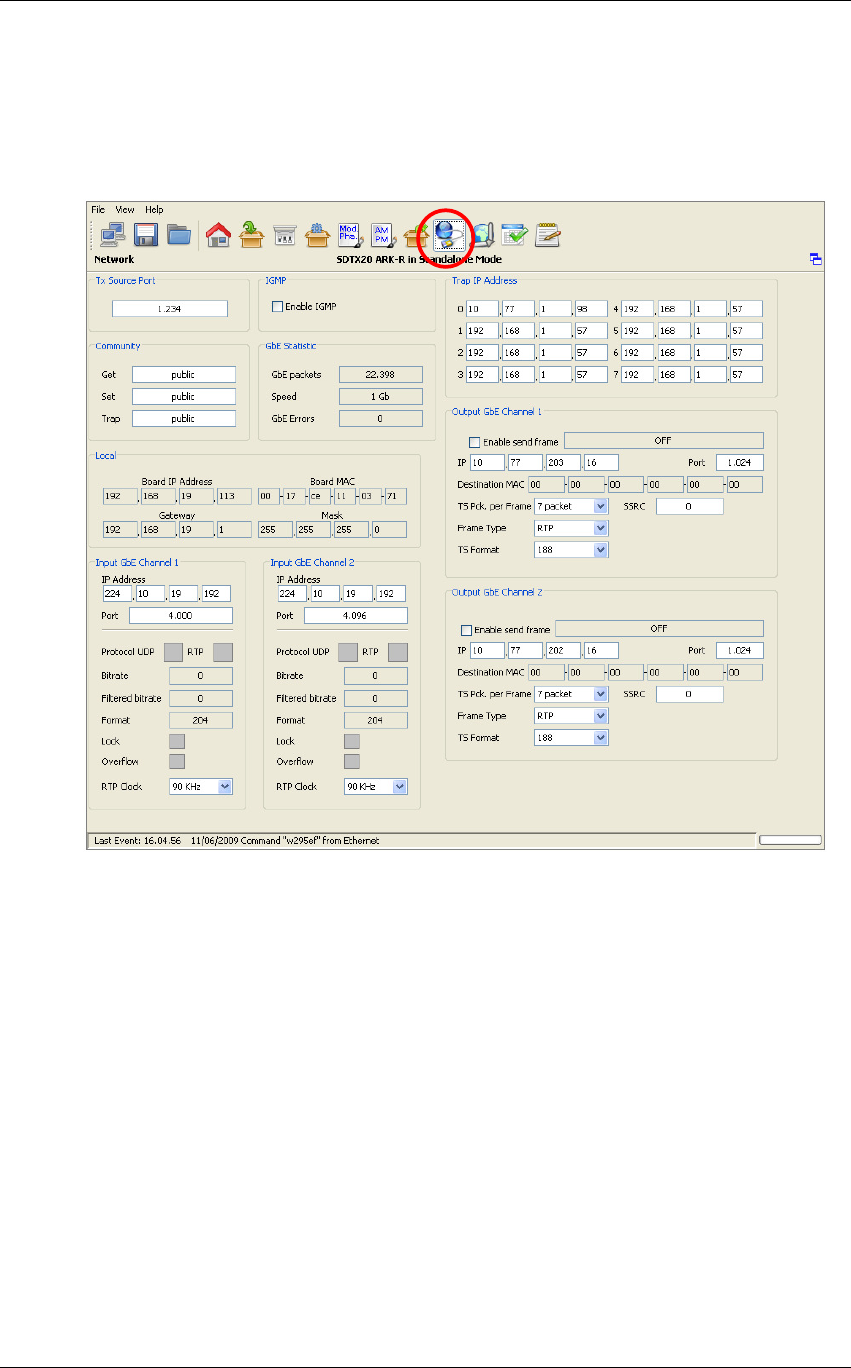
Screen Service SDT 501 UB-C ARK 1-T Operations
May, 2010 v 1.0 Page 3 - 83
3.6 NETWORK
Click on Network button icon, highlighted in the nex figure, to access the Network management
window.
This window allows the Network management on both PRO-MPEG COP 3 RX and TX sides. It
also allows the monitoring of the board IP and MAC addresses.
Note: The Clock Recovery Function, used in MFN transmissions of received streams on
Ethernet channels 1 and/or 2, is based on the timestamps of incoming packets. UDP packets do
not contain STS information therefore it is not allowed using GbE inputs with UDP protocol in
MFN transmission mode.

Screen Service SDT 501 UB-C ARK 1-T Operations
May, 2010 v 1.0 Page 3 - 84
Table 12. Network window
Box
Parameter /
Control Description Admitted Ranges / Values
Local Board IP address Board IP address.
Local Board MAC
address Board MAC address.
Local Gateway Gateway address.
Local Mask Net Mask.
Local Tx Source Port Board receiving port.
•
Min: 0
•
Max: 65,535
Trap IP address 0…7 Trap 0…7 destination IP address.
IGMP Enable IGMP IGMP enabling.
•
Checked: Enabled
•
Not checked: Disabled
Input GbE
Channel 1/2 IP Address Channel 1/2 receiving IP address.
Input GbE
Channel 1/2 Port Channel 1/2 receiving port.
•
Min: 0
•
Max: 65,535

Screen Service SDT 501 UB-C ARK 1-T Operations
May, 2010 v 1.0 Page 3 - 85
Box Parameter /
Control Description Admitted Ranges / Values
Input GbE
Channel 1/2 Protocol Ethernet input packets protocol.
•
UDP/RTP:
o Green: Detected
o Grey: Not detected
Input GbE
Channel 1/2 Bit-rate [bit/s] Bit-rate of TS from Ethernet input.
Input GbE
Channel 1/2
Filtered bit-rate
[bit/s] Bit-rate actually used by the modulator.
•
Zero when the input is not
selected
•
Equal to the total bit-rate,
when Delete Null Packets
disabled
•
Less than total bit-rate, when
Delete Null Packets enabled
Input GbE
Channel 1/2 Format Received transmission format.
•
188 Bytes
•
240 Bytes

Screen Service SDT 501 UB-C ARK 1-T Operations
May, 2010 v 1.0 Page 3 - 86
Box Parameter /
Control Description Admitted Ranges / Values
Input GbE
Channel 1/2 Lock Ethernet input lock status indicator. The input Transport Stream is locked when no more than two
consecutive Sync Byte are missed.
•
Green: Lock
•
Grey: Not locked
Input GbE
Channel 1/2 Sequence error NOT IMPLEMENTED (Ethernet input Sequence error alarm status. This alarm condition occurs
when an error in the sequence of input packets at IP level occurs.)
•
Red: Error
•
Grey: No errors
Input GbE
Channel 1/2 Overflow Input GbE overflow alarm status. This alarm condition occurs when the input bit-rate exceeds the
capability of the modulation (Ref. to ETSI EN 300 744).
•
Red: Alarm on
•
Grey: Alarm off
Input GbE
Channel 1/2 RTP Clock RTP packets source clock reference.
•
90 kHz
•
27 MHz
Gbe statistic GBE Packets Total amount of good frames received.

Screen Service SDT 501 UB-C ARK 1-T Operations
May, 2010 v 1.0 Page 3 - 87
Box Parameter /
Control Description Admitted Ranges / Values
Gbe statistic Speed Ethernet speed.
•
10 Mbit//s
•
100 Mbit//s
•
1 Gbit/s
Gbe statistic GBE Errors Total amount of bad frames received.
Community Get Read community setting.
Community Set Set community setting.
Community Trap Trap community setting.
Output GbE
Channel 1/2
Enable send
frame Channel 1/2 Ethernet transmission enabling.
•
Checked: Enabled
•
Not checked: Disabled
Output GbE
Channel 1/2 IP Channel 1/2 Ethernet transmission IP address.
Output GbE
Channel 1/2 Port Port used for RTP/UDP data transmission
•
Min: 0
•
Max: 65,535

Screen Service SDT 501 UB-C ARK 1-T Operations
May, 2010 v 1.0 Page 3 - 88
Box Parameter /
Control Description Admitted Ranges / Values
Output GbE
Channel 1/2 Status Ethernet transmission on channel 1/2 status indicator.
•
Resolving IP Addr.
•
IP not found
•
No entry
•
Transmitting data
•
Transmitting data multicast
•
No TS Input
•
ON
•
OFF
Output GbE
Channel 1/2 Destination MAC Destination MAC address.
Output GbE
Channel 1/2 SSRC SSRC identifier of the RTP transmission on channel 1-2.

Screen Service SDT 501 UB-C ARK 1-T Operations
May, 2010 v 1.0 Page 3 - 89
Box Parameter /
Control Description Admitted Ranges / Values
Output GbE
Channel 1/2 TS Pck per Frame Number of packets per frame.
•
Min: 1
•
Max: 7
Output GbE
Channel 1/2 Frame type Transmission protocol selector.
•
RTP
•
UDP
Output GbE
Channel 1/2 TS Format Transmission format.
•
188 Bytes
•
240 Bytes
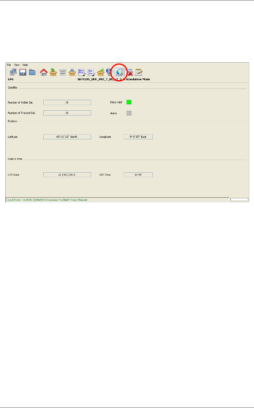
Screen Service SDT 501 UB-C ARK 1-T Operations
May, 2010 v 1.0 Page 3 - 90
3.7 GPS
Click on GPS button icon, highlighted in the nex figure, to access the GPS received statistics
window.
Figure 19. GPS window

Screen Service SDT 501 UB-C ARK 1-T Operations
May, 2010 v 1.0 Page 3 - 91
Table 13.
GPS window
Box
Parameter/
Control Description Admitted Ranges / Values
Satellite #Number of
Visible sat Number of visible GPS satellites indicator.
Satellite #Number of
Tracked sat Number of tracked GPS satellites indicator.
Satellite Alarm GPS alarm status indicator. This alarm is a logic OR between the GPS alarms (refer to
Alarms
paragraph).
•
Red: Alarm on
•
Grey: Alarm off
Satellite Data valid Valid satellite signal receiving status indicator.
•
Green: Valid
•
Grey: Not valid
Position Latitude (°) Site latitude expressed in degrees.
Position Longitude (°) Site longitude expressed in degrees.
Date & Time UTC Time
Current time indicator.
Each GPS satellite has an atomic clock and continually transmits messages containing the
current time and date at the start of the message sent by the GPS itself.
Date & Time UTC Date
Current date indicator.
Each GPS satellite has an atomic clock and continually transmits messages containing the
current time and date at the start of the message send by the GPS itself.
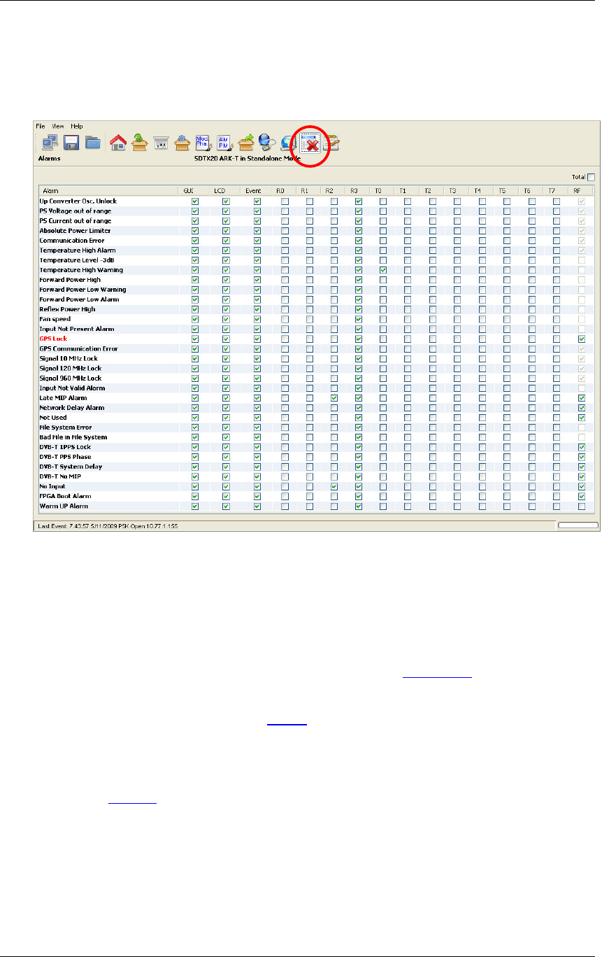
Screen Service SDT 501 UB-C ARK 1-T Operations
May, 2010 v 1.0 Page 3 - 92
3.8 ALARMS
Click on Alarms button icon, highlighted in the nex figure, to access the alarms management
window.
Figure 20. Alarms window
The Alarm window allows the setting of alarm masks and the monitoring of alarms status. Use
alarm masks to select how and which alarm have to be notified.
Masks are organized in columns. The sixteen columns represent sixteen destinations of each
alarm notification:
• GUI: the selected alarms status is notified on the Java alarm page icon.
• LCD: the selected alarms status is notified on LCD display lighting the alarm button
and listing the alarms in the Alarms menu (refer to LCD alarms paragraph).
• Event: the selected alarms status generate an alarm event that will be logged in
the event memory (refer to Events paragraph).
• R0…R3: the selected alarms switch on the corresponding relay.
• T0…T7: the selected alarms generate the corresponding trap messages (refer to
Network paragraph to set destination IP addresses).
• RF: the selected alarms switch off the output RF signal. The RF mask is almost
entirely fixed in order to avoid board damages or malfunctioning.
In the Alarms window, when an alarm condition occurs, the relative alarm is red highlighted. The
Total check box enables all alarms-to-masks associations. Remember to enable the RF Off
alarms mask of DVB-T alarms.

Screen Service SDT 501 UB-C ARK 1-T Operations
May, 2010 v 1.0 Page 3 - 93
Table 14. Alarms window
Alarm Description and limitations Troubleshooting
Up converter Osc. Unlock PLL of the Up converter board not locked to 120 MHz clock.
•
Hardware fault
PS Voltage out range (for STDX
20/50/201) or
PS1/PS2 Voltage alarm (for STDX
501)
Voltage out of range. The ranges are:
•
20V up to 30V for SDTx_ARK1-T SDTX 20/50;
•
38V up to 44V for SDTx_ARK1-T SDTX 201/501.
•
Hardware fault
PS Current out of range or (for STDX
20/50/201) or
PS1/PS2 Current alarm (for STDX
501)
The current exceeds the 22 Ampere upper limit of
SDTx_ARK1-T 20W and 50W and the 17 Ampere upper limit
of SDTx_ARK1-T 200W.
•
Hardware fault
Absolute Power Limiter The output power exceeds the maximum endurable limit.
•
Hardware fault
Up converter Communication error Communication errors between ARK1-T main board and
Up-converter board.
•
Hardware fault
Temperature High Alarm Case temperature over 70°C, the maximum endurable limit.
Temperature Level-3dB
Temperature level goes over the alarm threshold.
The output power is consequently lowered by 3 dBm (always
within the admitted power range).
Temperature High Warning Temperature level goes over the warning threshold.
•
Check alarm and warning thresholds
•
Lower the output power to decrease internal temperature

Screen Service SDT 501 UB-C ARK 1-T Operations
May, 2010 v 1.0 Page 3 - 94
Alarm Description and limitations Troubleshooting
•
Check the device airflow
•
Check fans
Forward Power High Forward power goes over the maximum endurable limit.
•
Verify that the No RF Input alarm is enabled in the RF Off alarms
mask
•
Hardware fault
Forward Power Low Warning Module difference between Forward power level and set
output power goes over the warning threshold.
Forward Power Low alarm Module difference between Forward power level and set
output power goes over the alarm threshold.
•
Check alarm and warning thresholds
•
At every amplifier initialization the forward power alarm and warning
may be temporary on
•
Amplifier is not properly working, hardware fault
Reflex Power High Reflex power goes over the maximum endurable limit.
•
Check the RF output for disconnection or wrong impendence
adaptation
Fan Speed One of the fans speed is under the minimum speed level
(1,000 rpm).
•
Check fans connections

Screen Service SDT 501 UB-C ARK 1-T Operations
May, 2010 v 1.0 Page 3 - 95
Alarm Description and limitations Troubleshooting
•
Verify that fans are not damaged; if they are, then substitute them.
The substitution can be performed during device normal operations
Input Not present Alarm
Seamless improper working warning
One or both Seamless logic input of the current mode isn’t
locked.
This alarm is enable only in Tx DVBT mode
•
Check connection status of physical input associated to logic input
•
Check type and source of input associated to logic input
•
Hardware fault
GPS Lock
GPS signal is not lock.
Alarm raising limitations:
The monitoring of this alarm is disabled when GPS is not
used as clock reference or when the GPS Communication
Error is raised.
•
Check cable and GPS antenna connections
•
Hardware fault
GPS Communication Error
Communication errors between ARK1-T main board and
GPS board.
Alarm raising limitations:
The monitoring of this alarm is disabled when GPS is not
used as clock reference.
•
Hardware fault
Signal 10 MHz Lock
10 MHz is not locked.
Alarm raising limitations:
The monitoring of this alarm is disabled when GPS is used
as clock reference and a GPS alarm (GPS lock, GPS
•
If the Network’s Transmitters Synchronization is SFN, check the
frequency reference: it should be other than internal

Screen Service SDT 501 UB-C ARK 1-T Operations
May, 2010 v 1.0 Page 3 - 96
Alarm Description and limitations Troubleshooting
communication error) is raised.
•
If the frequency reference is Internal: internal PLL fault
•
If the frequency reference is External:
o Internal PLL fault
o Lack of external 10 MHz
o Hardware fault
•
If the frequency reference is GPS:
o Internal PLL fault
o 10 MHz line from the GPS receiver hardware fault
Signal 120 MHz Lock
120 MHz is not locked.
Alarm raising limitations:
The monitoring of this alarm is disabled when the signal 10
MHz lock alarm is raised or when GPS is used as clock
reference and a GPS alarm (GPS lock, GPS communication
error) is raised.
•
In SFN configuration, when selected TS input or MIP are not
detected, 120 MHz oscillator can lose the lock
•
Hardware fault

Screen Service SDT 501 UB-C ARK 1-T Operations
May, 2010 v 1.0 Page 3 - 97
Alarm Description and limitations Troubleshooting
Signal 960 MHz Lock 960 MHz is not locked.
•
Hardware fault
Input Not valid
Seamless improper working warning
An error has been detected on Logical seamless input. The
possible errors which may be detected on input are:
•
PAT error
•
MIP error
•
TS synchronization
•
Packet jitter
•
Transport error
•
ASI word error
When the alarm is detected, an event (if event mask is
enabled on alarm mask) shows the cause of the error. The
cause shown is only one, and it is the heaviest one. The
priority in the errors is as previously listed (the heaviest error
cause is the one listed in the bottom of the list, and so on).
•
Check input signal
•
Check cable connection status
•
Hardware fault

Screen Service SDT 501 UB-C ARK 1-T Operations
May, 2010 v 1.0 Page 3 - 98
Alarm Description and limitations Troubleshooting
Late MIP input alarm
Seamless improper working warning
This alarm is high when the MIP in one of the seamless
inputs of the current mode, is not in its expected position.
This can be caused by a too high delay on the input.
•
Check cable connections
•
Check Network delay
•
Hardware Fault
Network delay alarm
Seamless improper working warning
This alarm is high when the Network delay parameter,
calculated from parameters extracted by a seamless inputs is
greater than the Maximum delay parameter, extracted from
its MIP
The alarm can be visualized when LATE MIP input 1 alarm is
not high.
•
Check cable connections
•
Check Network delay
•
Hardware Fault
Not Used This alarm isn’t used
File System Error File System loading error.
•
File system partition damage

Screen Service SDT 501 UB-C ARK 1-T Operations
May, 2010 v 1.0 Page 3 - 99
Alarm Description and limitations Troubleshooting
Bad File in File system
One or more of the following files is missing in the File
System.
•
*.def;
•
*.sav;
•
*.dpwr;
•
*.apwr
•
*.dlin;
•
*.dpre;
•
*.apre
•
*.cfg;
•
*.gdly.
•
*.cdef
•
Check files list
•
Reload the file system

Screen Service SDT 501 UB-C ARK 1-T Operations
May, 2010 v 1.0 Page 3 - 100
Alarm Description and limitations Troubleshooting
DVB-T 1PPS Lock
1PPS is not lock to the selected frequency reference. This
alarm’s RF OFF mask should always be enabled.
Alarm raising limitations:
The monitoring of this alarm is disabled when external 1 PPS
is not used (Heterodyne repeater modes) or when internal 1
PPS is selected (clock ref. set to internal) or when GPS clock
reference is selected and one of the GPS alarms (GPS
signal lock, GPS comm. alarm) is raised.
•
If the frequency reference is Internal: internal PLL fault
•
If the frequency reference is External:
o Internal PLL fault
o Lack of external 1PPS
o Hardware fault
•
If the frequency reference is Internal:
o Check GPS alarms
o Internal PLL fault
o Hardware fault
DVB-T PPS Phase
1PPS is not lock to a common reference of the network. This
alarm’s RF OFF mask should always be enabled.
Alarm raising limitations:
The monitoring of this alarm is enabled only when the device
has SFN modulation enabled.
•
Check 1PPS
•
Hardware fault

Screen Service SDT 501 UB-C ARK 1-T Operations
May, 2010 v 1.0 Page 3 - 101
Alarm Description and limitations Troubleshooting
DVB-T System Delay
The internal counter, used to apply the System delay is not
lock to 1 PPS. This alarm’s RF OFF mask should always be
enabled.
Alarm raising limitations:
The monitoring of this alarm is enabled only when the device
has SFN modulation enabled.
•
Check 1PPS
•
Hardware fault
DVB-T No MIP
MIP packets missing. This alarm’s RF OFF mask should
always be enabled.
Alarm raising limitations:
The monitoring of this alarm is enabled only when the device
has SFN modulation enabled.
The monitoring of this alarm is disabled when a No Input
alarm is raised.
•
Check input signal
No Input
DVB: Selected TS input not locked. Only when ASI and GBE
inputs are selected as input HP and/or LP. This alarm’s RF
OFF mask should always be enabled.
ITU: Selected SDI Input not present or video standard (525
or 625 lines) not compatible with modulator one as defined
by parameter LINE_625_525 in .mod file (1=625).
•
Check input statistics
FPGA Boot alarm FPGA boot has not been successfully completed.
•
Restart the machine
•
Reload the file system

Screen Service SDT 501 UB-C ARK 1-T Operations
May, 2010 v 1.0 Page 3 - 102
Alarm Description and limitations Troubleshooting
Warm up alarm Temperature level less than 5°C or temperature sensor fault.
•
Restart the machine
•
Temperature sensor fault
Notes to the table:
• 0/1 stands for disabled/enabled and is fixed, X stands for not fixed.
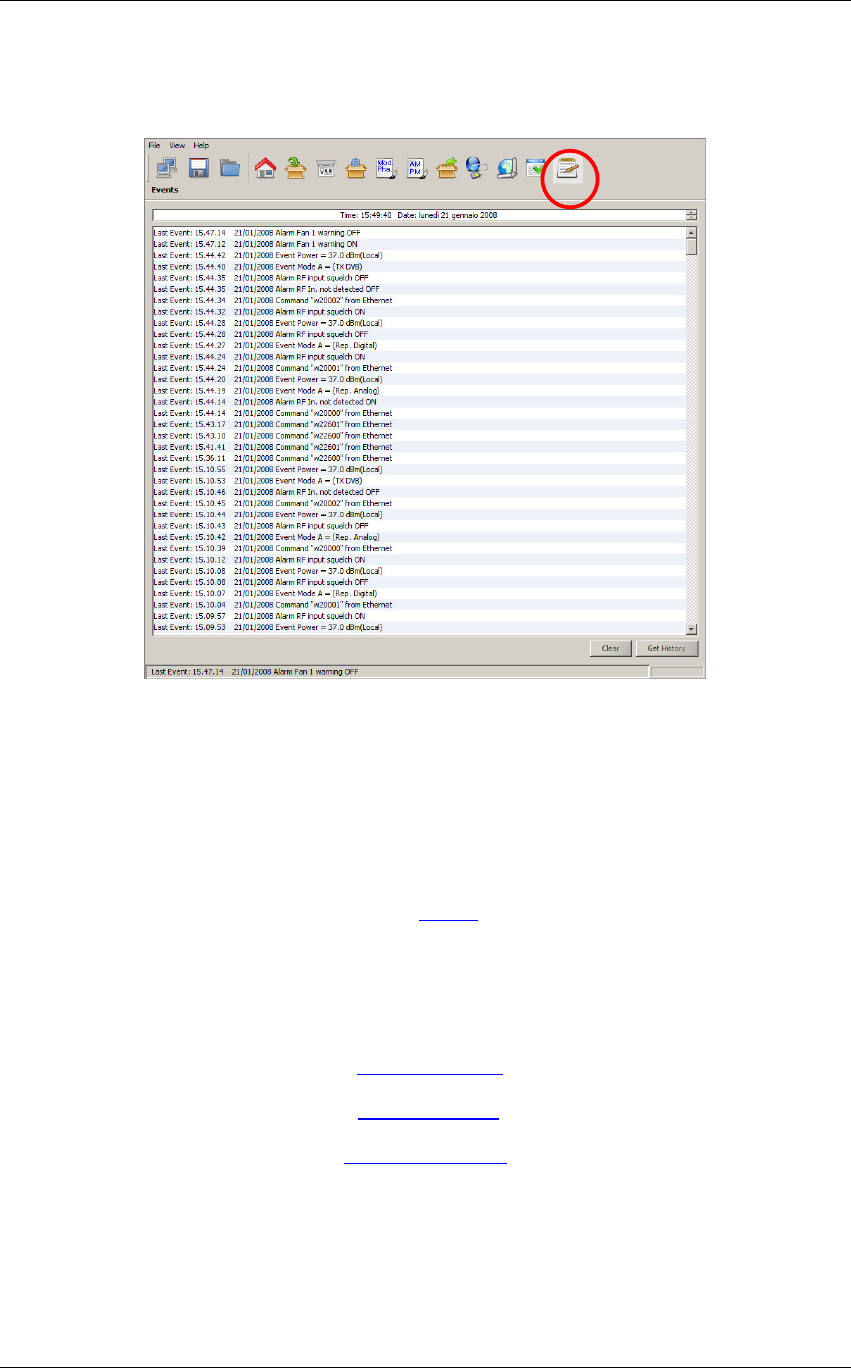
Screen Service SDT 501 UB-C ARK 1-T Operations
May, 2010 v 1.0 Page 3 - 103
3.9 EVENTS
Click on Events button icon, highlighted in the nex figure, to access the events windos.
Figure 21. Events window
Open the Events window to slide the events list.
Events are reported with the following information:
• Time: event detection time.
• Date: event detection date.
• Type: event type:
o Alarm (refer to alarms list in Alarms paragraph and to Alarms list table);
o Command (See ARK1-T_SW_Reference manual_v1_2.doc for further
information);
o Event (refer to Events list table);
o System Init (refer to Init System Event paragraph);
o TASK_ERR (refer to Task Error Event paragraph);
o SYS_ERR (refer to System Error Event paragraph).
• Description: event description:
o Alarm: which alarm generated the event;
o Command: the low level code and command source;

Screen Service SDT 501 UB-C ARK 1-T Operations
May, 2010 v 1.0 Page 3 - 104
o Event: event description;
o System Init: system initialization, followed by the alarm in case of error.
• Color: at different color is associated different kind of event:
o Red: alarm event;
o Green: command event;
o Blue: system event;
o Black: information event (It give more information about the former event).
Use the following buttons, sited on the right side of the window, to manage the Events list:
• Clear: resets the events list.
• Get History: gets all the stored events from the last board reset (max 512 events).

Screen Service SDT 501 UB-C ARK 1-T Operations
May, 2010 v 1.0 Page 3 - 105
Table 15.
Events list
Event Description Description
RF OFF enabled from OPTO RF output switched off through OPTO 0.
RF OFF disabled from OPTO RF output switched on through OPTO 0.
Stand-by ON from OPTO Stand-by mode enabled through OPTO 3.
Stand-by OFF from OPTO Stand-by mode disabled through OPTO 3.
Stand-by ON from LCD Stand-by mode enabled through LCD button.
Stand-by OFF Stand-by mode disabled through LCD button.
Power =
xx.x
dBm (
source
)
New output power setting.
xx.x
: output power expressed in dBm.
Source
: Local or MIP
Update file *.
xxxx
New file loading.
xxxx
: file extension.
Delete file *.
xxxx
A file in file system has been deleted.
Xxxx
: file extension.
P5K open:
xx.xx.xx.xx
Connection to port 5000 open.
xx.xx.xx.xx:
host IP address.
P5K closed Connection to port 5000 closed.
Switch mode
switch
X
=>
Y
Switch mode change.
Switch mode
: Manual / Auto / Opto / Time.
X
=>
Y
: A/B=>B/A.
UPCV not configured
The Up-converter has been found not configured during the
UPCV_TASK (refer to
Task Error Event
paragraph).
UPCV configured Automatic reconfiguring of the Up-converter. It automatically starts at
every UPCV not configured event or UPCV communication error.
File system busy File system already in use while trying to employ it (e.g. change mode
during a file loading).
UTC Time set from GPS
Time and date set by GPS. As soon as the GPS lock is regained,
once lost, and if the current time and date are different from the GPS
ones, the UTC time is set by GPS.
Warm UP Restart When Warm up alarm is raised this event is reported and the device
is restarted.

Screen Service SDT 501 UB-C ARK 1-T Operations
May, 2010 v 1.0 Page 3 - 106
Event Description Description
PS Restart
N
This event is reported when one of the following alarms is raised:
•
Up converter Osc. Unlock
•
PS 28V out range
•
PS Current out of range
•
Absolute Power Limiter
The fourth time one of the preceding alarms is risen the amplifier is
restarted (from 1 up to 4 times).
N:
number of amplifier restarting.
Only in SDTX 200 version.
PS OFF
After the fourth time the amplifier has been restarted, if an alarm
condition causing a PS Restart event occurs, PS OFF event is
reported and the amplifier is turned off
When this event is reported amplifier can be turned on only by OPTO
2 (oonly in SDTX 200 version).
Restart Amp from OPTO
This event is reported when the retry command is given by the Retry
Alarm OPTO (OPTO 2).
Only in SDTX 200 version.
PS ON This event is reported at every amplifier restarting
Only in SDTX 200 version.
FPGA Re-config When Signal 120 MHz Lock alarm is risen the FPGA is re-configured
and this event is reported.
Events List cleared This event is reported when the events list is cleared.
Saving config… Saving configuration task started (after the command “s” given by
RS232 or GbE commands).
Save config Finished Saving configuration task correctly ended.
Save config error:
xx
An error occurs during saving configuration.
xx:
error code:
•
0x80: File system busy;
•
0x01: New *.sav file opening error;
•
0x02: FPGA data writing error;
•
0x03: uC data writing error;
•
0x05: Old *.sav file deleting error
•
0x06: New file naming error (deleting of “*”).

Screen Service SDT 501 UB-C ARK 1-T Operations
May, 2010 v 1.0 Page 3 - 107
Event Description Description
SFN Re-Sync A re-synchronization of internal counter occurred due to a difference
with the STS parameter read from MIP.
3.9.1 Date and time setting
The upper part of the event window shows the actual time and date and allows the manual
setting of those parameters.
Figure 22. Time and date setting
Click to each part of the date and time to change the parameter and then increase or
decrease its value with the up/down arrows.
Note: When the onboard GPS receiver is locked and GPS frequency reference is enabled,
the date and time information are received by GPS satellite and updated every thirty
seconds.
The board incorporates a rechargeable battery to maintain the time when there isn’t a power
supply. The battery supplies the clock for two or three days, after that the time shall be reset
either by char interface, or LCD display, or Java interface or selecting the GPS as frequency
reference.

Screen Service SDT 501 UB-C ARK 1-T Operations
May, 2010 v 1.0 Page 3 - 108
3.9.2 Task Error Event
The watchdog performs a periodic (every 20 seconds) polling of tasks and triggers a system
reset if one or more tasks do not answer, restarting the Codeloader (See
Codeloader_Operations_Note_v1.1.doc for further information) and generating a TSK ERR
event as follows:
The blue underlined 8 bits word is the enabling status of the alarms mask. The red
underlined 8 bits word indicates the status of tasks (1 if the task has been successfully
performed, otherwise 0) as specified in the following table:
Table 16. Task error event specific data
TASK Description Bit
WD_FAN_TASK This task controls fans speed on the base of the
board temperature. 0
WD_UPCV_TASK This task controls the Upconverter status. 1
WD_GPS_TASK This task controls the GPS status. 2
WD_STATUS_TASK
This task gathers quite all the board information in
order to perform the following operations:
•
It updates all variables of the system;
•
It manages alarms;
•
It manages the RF status (e.g. on, off…);
•
It manages the mode switch;
•
It manages the ARP resolution in DVB mode.
3
WD_TCP_IP_TASK This task implements the TCP-IP protocol stack. 4
WD_TIMER_TICK_TASK This task generates the clock for the TCP-IP task. 5
WD_STV0362_TASK This task gathers information from both the HP and
LP tuners and configures them. 6
The default tasks mask at the board startup is set to 0x0000007D (i.g. the UPCV task is
excepted). Once the presence of the upconverter is assured, the upconverter task bit is
automatically enabled and the mask is set to 0x0000007F. Tasks execution is stopped
during de-fragmentation operations and FPGA boots.
TSK ERR
00000028
,
0000003c

Screen Service SDT 501 UB-C ARK 1-T Operations
May, 2010 v 1.0 Page 3 - 109
3.9.3 System Error Event
For critical and fatal errors, the system calls the system error function and the
SYS_ERR
event is
reported.
The error code is described below:
•
0x00: Out of memory. Memory pool size is too small.
•
0x01: Invalid memory block release. Buffer data has been written out of boundaries of the
allocated memory block.
•
0x02: Link pointer corrupted. Buffer data has been written out of boundaries of the allocated
memory block.
•
0x03: No free UDP Sockets. The system has run out of UDP Sockets.
•
0x04: No free TCP Sockets. The system has run out of TCP Sockets.
•
0x05: TCP socket is in an undefined state. System memory has been accidentally overwritten.

Screen Service SDT 501 UB-C ARK 1-T Operations
May, 2010 v 1.0 Page 3 - 110
3.9.4 System Initialization Event
At every system initialization the event System Init is generated.
This event is followed by 25 bytes specifying type and specific code of errors occurred
during system initialization.
Each byte refers to an error as described in the following table:
Table 17. Init system event specific data
Byte Description Errors code
1° FS_ERR
File System error.
•
0x00: File System ok.
•
0x01: FS partition error (invalid FS).
2° INFO_ERR
*.cfg file error.
•
0x00: File ok.
•
0x01: File not found or File open error.
•
0x02…0x03: Invalid file (syntax errors).
3° DEF_ERR
*.def file error.
•
0x00: File ok.
•
0x01: File open error.
•
0x02: File not found.
4° LCD_ERR
LCD error.
•
0x00: LCD ok.
•
0x01: LCD not found.
5° PLL_960M_ERR
960 MHz PLL error.
•
0x00: PLL locked.
•
0x01: PLL not locked

Screen Service SDT 501 UB-C ARK 1-T Operations
May, 2010 v 1.0 Page 3 - 111
Byte Description Errors code
6° BOOT_ERR
FPGA boot error.
•
0x00: FPGA boot ok.
•
0x01: FPGA configuration erasing
process error.
•
0x02: Invalid configuration (the
configuration has been correctly loaded,
but the FPGA doesn’t boot).
•
0x10: FPGA file not found.
•
0x11 and 0x20: Invalid FPGA file (syntax
error).
Please note that checked FPGA file is the
one which refers to the selected mode.
FPGA files are numbered from 1 to 3,
identifying Heterodyne mode, TX DVB mode,
TX Analog mode.
7° LOAD_CFG_ERR
*.sav file error.
•
0x00: File ok.
•
0x01: File open error.
•
0x02…0x05: Invalid file (syntax errors).
•
0x10: File not found.

Screen Service SDT 501 UB-C ARK 1-T Operations
May, 2010 v 1.0 Page 3 - 112
Byte Description Errors code
8° SNMP_ERR
SNMP file error.
•
0x00: SNMP file ok.
•
0x01: SNMP file not found.
•
0x02: File open error.
•
0x03: UDP socket initialization error.
•
0x04: Port 161 open error.
9°
CALIB_ERR
*.apwr and *.dpwr files
error.
•
0x00: File ok.
•
0x01: Current AGC mode file not found.
•
0x02: Current AGC mode file open error.
•
0x03…0x12: Invalid current AGC mode
file (syntax error).
•
0x20: Other AGC mode file not found
•
0x21: Other AGC mode file open error.
•
0x22…0x26: Invalid other AGC mode file
(syntax error).
Please note that the AGC mode may be
analog (in case of device in Rep. Analog or
ITU 470 mode) or digital (in case of device in
Rep. Digital or TX DVB mode).
Actual AGC mode is displayed in Java output
window.

Screen Service SDT 501 UB-C ARK 1-T Operations
May, 2010 v 1.0 Page 3 - 113
Byte Description Errors code
10°
PREC_ERR
*.apre and *.dpre files
error.
•
0x00: File ok.
•
0x01: File not found.
•
0x02: File open error.
•
0x03…0x0a: Invalid file (syntax errors).
Please note that *.apre file is checked if
device starts in AGC analog mode (rep.
analog or ITU 470 mode), while *.dpre file is
checked if device starts in AGC digital mode.
11°
LINEAR_ERR
*.alin and *.dlin files
error.
•
0x00: File ok.
•
0x01: File not found.
•
0x02: File open error.
•
0x03…0x0A: Invalid file (syntax errors).
Please note that the *.alin file is used for the
Heterodyne Repeater modes (Rep. Analog
and Rep. Digital), and the *.dlin file is used
for the DVB re-transmitter and ITU 470 re-
transmitter modes.
12°
DOWNCV_ERR
Downconverter PLL not
locked error.
•
0x00: PLL locked.
•
0x01: PLL not locked
•
0x10: PLL disabled.

Screen Service SDT 501 UB-C ARK 1-T Operations
May, 2010 v 1.0 Page 3 - 114
Byte Description Errors code
13° UPCV_ERR
Upconverter error.
•
0x00: Upconverter ready.
•
0x01: Upconverter not found.
•
0x02: Upconverter doesn’t correctly
answer.
•
0x10: Upconverter disabled.
14°
CH_FILT_ERR
*.chf7 or *.chf8 file
error.
•
0x00: File ok.
•
0x01: File not found.
•
0x02: File open error.
•
0x03…0x06: Invalid file (syntax errors).
Please note that checked file is the one
which refers to the current signal bandwidth:
*.chf7 refers to VHF bandwidth, *.chf8 refers
to UHF bandwidth.

Screen Service SDT 501 UB-C ARK 1-T Operations
May, 2010 v 1.0 Page 3 - 115
Byte Description Errors code
15° CH_DEF_ERR
*.cdef file error.
•
0x00: File ok.
•
0x01: File not found.
•
0x02: File open error.
•
0x03: syntax error or lack of input
number of channels.
•
0x13: syntax error or lack of output
number of channels.
•
0x04: input channels memory allocation
error.
•
0x14: output channels memory
allocation error.
•
0x05: when the automatic indexing of
channels listed in *.cdef file is disabled,
it notifies syntax errors or lack of input
channels definition lines.
•
0x15: when the automatic indexing of
channels listed in *.cdef file is disabled,
it notifies syntax errors or lack of output
channels definition lines.
•
0x06: when the automatic indexing of
channels listed in *.cdef file is enabled, it
notifies syntax errors or lack of input
channels definition lines.
•
0x16: when the automatic indexing of
channels listed in *.cdef file is enabled, it
notifies syntax errors or lack of output
channels definition lines.
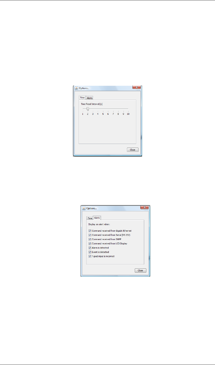
Screen Service SDT 501 UB-C ARK 1-T Operations
May, 2010 v 1.0 Page 3 - 116
3.10 Option sub-menu
The Option sub-menu allows two controls type:
• Time: Time Read Interval [s];
• Alerts: the selection of events to display.
3.10.1 Time
Figure 23. Time subwindow
This control allows to change the device-to-management PC java update time. The default
value is 2 seconds. Click on Close button quit this sub-window.
3.10.2 Alerts
Figure 24. Alerts subwindow
The Alert subwindow allows the selection of which type of event has to be notified through
an Alert box.
Alert boxes appear on the right side of the monitor. The selection is performed among the
following types of event:
• Commands (blue boxes):
o Gigabit Ethernet commands;
o RS232 commands;
o SNMP commands;
o LCD Display commands.
• Alarms (red boxes);
• Events (green messages):

Screen Service SDT 501 UB-C ARK 1-T Operations
May, 2010 v 1.0 Page 3 - 117
o Board events.
• Typing error (yellow messages):
o Typed setting is incorrect.
Click on Close button to hide theses alert subwindows.
Figure 25. Alert message
Alert boxes can be disabled through the hide button located on the right side of the box.
The hide button, once clicked, disables all boxes belonging to the same class.
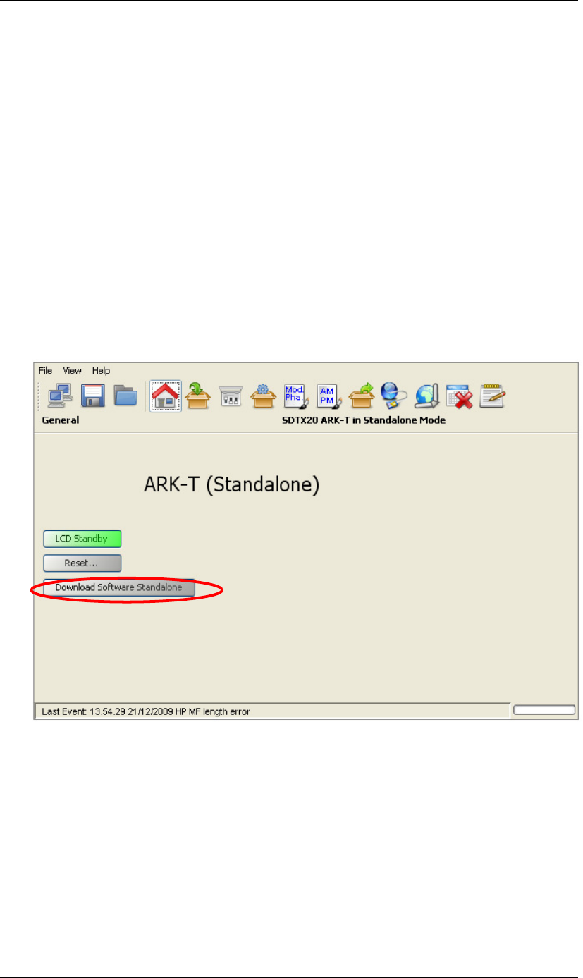
Screen Service SDT 501 UB-C ARK 1-T Operations
May, 2010 v 1.0 Page 3 - 118
3.11 Download Software Standalone
The Download Software Standalone button allows the downloading of standalone java
application (executable jar file) based on java applet.
If your browser is Internet Explorer, it may blocks the site from downloading files to your
computer. If you want to enable the file downloading, follow the instructions listed below:
• Open Internet Explorer;
• Click on the Tools button and then click on Internet Options;
• Click on the Security tab and then click on Custom level button;
• To turn off the Information bar for file downloads, scroll to the Downloads section of
the list, and then, under Automatic prompting for file downloads, click on Enable;
• Click on OK, click Yes in order to confirm that you want to make the change, then
click OK again.
Figure 26. Download Software Standalone

Screen Service SDT 501 UB-C ARK 1-T Operations
May, 2010 v 1.0 Page 3 - 119
3.12 SNMP – Simple Network Management Protocol
The SNMP model assumes the existence of managers and agents. A manager is a software
module in a management system responsible for managing the device. An agent is a
software module in a managed device responsible for maintaining local management
information and delivering that information to a manager via SNMP. A management
information exchange can be initiated by the manager (via polling) or by the agent (via trap).
Interaction between a user of board management and the board management software
takes place across a user interface. Such an interface is needed to provide users with a
monitoring and controlling tool in order to allow some parameters to be viewed or set locally.
The operations that are supported in SNMP network management are the alteration and
inspection of variables. Specifically, three general-purpose operations may be performed on
scalar objects:
• Get: a management station retrieves a scalar object value from a managed station.
• Set: a management station updates a scalar object value in a managed station.
• Trap: a managed station sends an unsolicited scalar object value to a management
station.
Management information accessible via SNMP is maintained in a management information
base (MIB) at each manager and agent node.
On manager side, ARK1-T management system has been tested with MG-SOFT as MIB
Browser; besides compatibility with any other MIB browser is assured.
The following MIB libraries are required for the SNMP management of the equipment:
• SCREENSERVICE-SCB-BROADCASTING-MIB.my;
• ark1_r_1_7.MY.
Compatibility tested and assured with SNMP version 1 and 2.
Figure 29 shows a sample view of SNMP tree structure of ARK1-T.
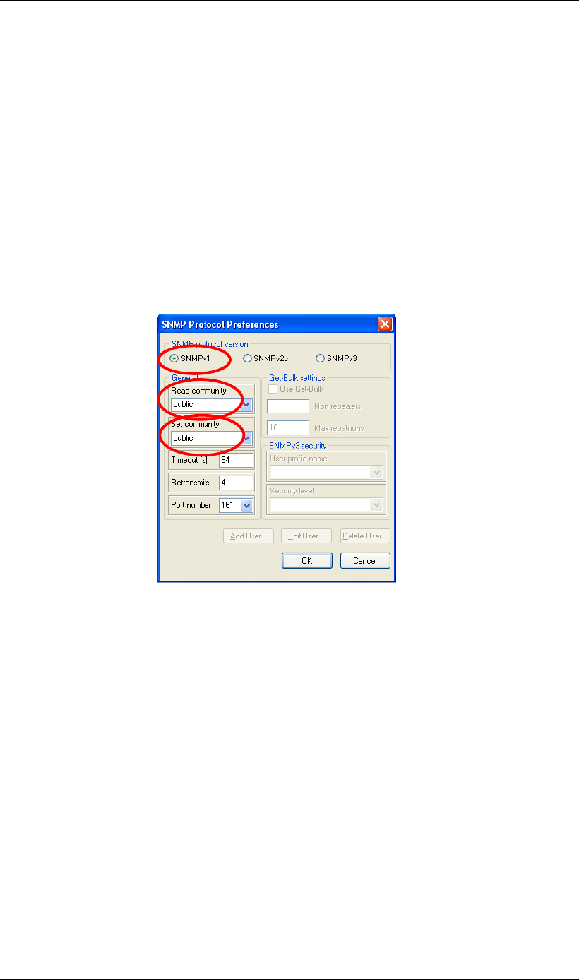
Screen Service SDT 501 UB-C ARK 1-T Operations
May, 2010 v 1.0 Page 3 - 120
3.13 SNMP Protocol Preferences
Go to SNMP Protocol Preferences. The following parameters should be set in order to
correctly configure the SNMP Manager:
• SNMP protocol version: SNMPv1;
• Read Community: the same of the one set in the Get field of Java interface,
community section;
• Set Community: the same of the one set in the Set field of Java interface,
community section;
• Timeout [s]: user defined;
• Retransmits: user defined;
• Port number: 161.
Next figure illustrates how to configure SNMP Protocol Preferences using MG_SOFT MIB
Browser as an example.
Figure 3.12-1: SNMP Protocol Preferences
Community on the SNMP Protocol Preferences.
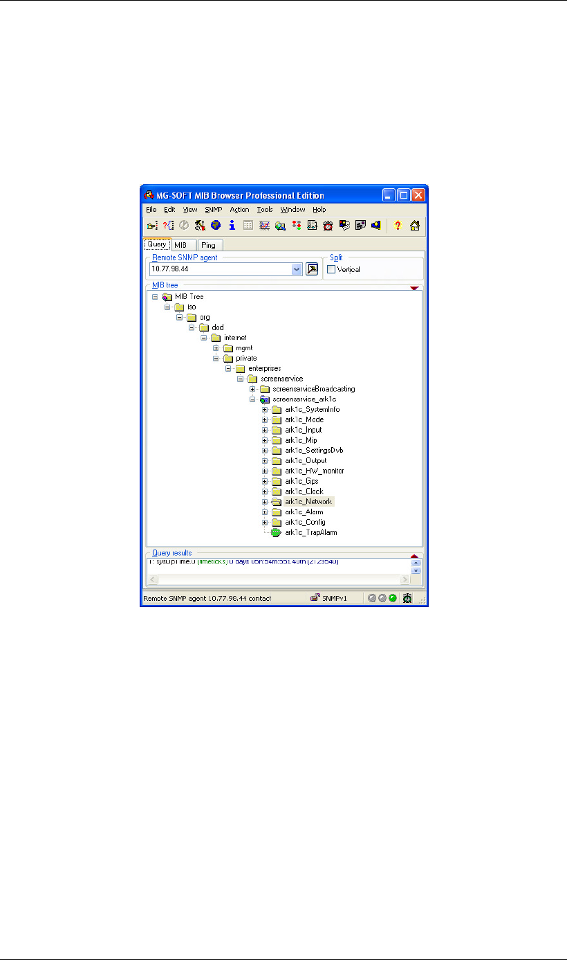
Screen Service SDT 501 UB-C ARK 1-T Operations
May, 2010 v 1.0 Page 3 - 121
3.14 Monitoring
All status and setup information can be queried via SNMP. To get the setup and status
information you need a management system (or a special MIB browser).
Next figure, referring to MG-SOFT MIB Browser as an example, is a broad view of the
ARK1-T tree structure.
Figure 27. ARK1-T MIB Browser

Screen Service SDT 501 UB-C ARK 1-T Operations
May, 2010 v 1.0 Page 3 - 122
3.15 OID
Any status and setup information has an OID (Object Identifier). The OID of the ARK1-T
system is:
• screenservice_ARK1r: 1.3.6.1.4.1.21678.188
iso(1).org(3).dod(6).internet(1).private(4).enterprises(1).screenservice(21678).scree
nservice_ARK1t(188)
3.15.1 SNMP tree structure
The SNMP tree structure is shown in Figure 26, after the node screenserviceBroadcasting
there is the node that specifies the device typology.
The screenservice_ARK1-T tree has 12 nodes and 1 leave.
The nodes are:
• Ark1t_SystemInfo: global description of the system.
• Ark1t_Mode: shows and manages board modes.
• Ark1t_Input: shows and manages inputs.
Note: In Ark1t_STV0 and Ark1t_STV1 nodes are housed the statistics of the digital
RF signal. STV0 and STV1 are the two IF demodulators for the HP and LP streams
respectively.
• Ark1t_Mip: shows MIP modulation parameters.
• Ark1t_SettingsDvb: shows and sets local modulation parameters.
• Ark1t_Output: shows and manages the output.
• Ark1t_HW_monitor: shows the amplifier status.
• Ark1t_Gps: shows the collection of live data from GPS receiver.
• Ark1t_Clock: shows and sets 10MHz and 1PPS source.
• Ark1t_Network: shows and sets network parameters.
• Ark1t_Alarm: shows and manages system alarms.
• Ark1t_Config: allows the management of the machine configuration.
• Ark1t_TrapAlarm: is the OID used in the trap message:

Screen Service SDT 501 UB-C ARK 1-T Operations
May, 2010 v 1.0 Page 3 - 123
OID Name R/W Description
1 iso
1.3 org
1.3.6 dod
1.3.6.1 internet
1.3.6.1.2 mgmt
1.3.6.1.2.1 mib-2
1.3.6.1.2.1.1 system
1.3.6.1.2.1.1.1 sysDescr R
1.3.6.1.2.1.1.2 sysObjectID R
1.3.6.1.2.1.1.3 sysUpTimeInstance R
1.3.6.1.2.1.1.4 sysContact R
1.3.6.1.2.1.1.5 sysName R
1.3.6.1.2.1.1.6 sysLocation R
1.3.6.1.2.1.1.7 sysServices R
1.3.6.1.4 private
1.3.6.1.4.1 enterprise
1.3.6.1.4.1.21678 screenservice
1.3.6.1.4.1.21678.188 screenservice_ark1t
1.3.6.1.4.1.21678.188.1 ark1t_SystemInfo
1.3.6.1.4.1.21678.188.1.1 ark1t_SystemInfoIdentifier R
Identification name
of the equipment
managed
1.3.6.1.4.1.21678.188.1.2 ark1t_SystemInfoName R
Manufacturer
name
1.3.6.1.4.1.21678.188.1.3 ark1t_SystemInfoDescription R
Description of the
equipment
managed
1.3.6.1.4.1.21678.188.1.4 ark1t_SystemInfoLocation R
Geographical
implantation
1.3.6.1.4.1.21678.188.1.5 ark1t_SystemInfoContact R
The person to
contact in case of
problems with the
managed element
1.3.6.1.4.1.21678.188.1.6 ark1t_SystemInfoFamilyNumber R Unique family ID
1.3.6.1.4.1.21678.188.1.7 ark1t_SystemInfoId R System info ID
1.3.6.1.4.1.21678.188.1.8 ark1t_SystemInfoSerialNumber R Unique board ID
1.3.6.1.4.1.21678.188.1.9 ark1t_SystemInfoVersion
1.3.6.1.4.1.21678.188.1.9.1 ark1t_VersionUc R UC file version
1.3.6.1.4.1.21678.188.1.9.2 ark1t_VersionFpga R Fpga file version
1.3.6.1.4.1.21678.188.1.9.3 ark1t_VersionSnmp R Snmp file version
1.3.6.1.4.1.21678.188.1.9.4 ark1t_VersionPsu
1.3.6.1.4.1.21678.188.1.9.4.1 ark1t_PsuFamily R
PSU unique family
ID
1.3.6.1.4.1.21678.188.1.9.4.2 ark1t_PsuSerial R
PSU unique board
ID
1.3.6.1.4.1.21678.188.1.9.5 ark1t_VersionUpconverter
1.3.6.1.4.1.21678.188.1.9.5.1 ark1t_UpconverterFamily R
Upconverter
unique family ID
1.3.6.1.4.1.21678.188.1.9.5.2 ark1t_UpconverterSerial R
Upconverter
unique board ID
1.3.6.1.4.1.21678.188.1.9.5.3 ark1t_UpconverterVer R
Upconverter
software version
1.3.6.1.4.1.21678.188.1.10 ark1t_SystemSerialNumbers
1.3.6.1.4.1.21678.188.1.10.1 ark1t_Device R
Device Serial
Number
1.3.6.1.4.1.21678.188.1.10.2 ark1t_Board R
Board Serial
Number
1.3.6.1.4.1.21678.188.1.10.3 ark1t_DownConverter R
Downconverter
Serial Number
1.3.6.1.4.1.21678.188.1.10.4 ark1t_UpConverter R
Upconverter Serial
Number
1.3.6.1.4.1.21678.188.1.10.5 ark1t_Psu R
Power Supply Unit
Serial Number

Screen Service SDT 501 UB-C ARK 1-T Operations
May, 2010 v 1.0 Page 3 - 124
OID Name R/W Description
1.3.6.1.4.1.21678.188.1.10.6 ark1t_Amplifier R
Amplifier Serial
Number
1.3.6.1.4.1.21678.188.2 ark1t_Mode
1.3.6.1.4.1.21678.188.2.1 ark1t_ModeSwitch RW
Switch mode
selector
0:manual 1:auto
2:opto 3:time
1.3.6.1.4.1.21678.188.2.2 ark1t_ModeManualSelector RW
Manual mode 0:
modeA 1: modeB
1.3.6.1.4.1.21678.188.2.3 ark1t_ModeActual R
Actual mode 0:
modeA 1: modeB
1.3.6.1.4.1.21678.188.2.4 ark1t_ModeSelectorA RW
Mode A selector
0: Not used, 1: Not
used, 2: Tx Digital
3: Tx Analog
1.3.6.1.4.1.21678.188.2.5 ark1t_ModeSelectorB RW
Mode B selector
0: Not used, 1: Not
used, 2: Tx Digital
3: Tx Analog
1.3.6.1.4.1.21678.188.2.6 ark1t_ModeErrorFrequency R
NOT
IMPLEMENTED
Frequency error
correction
expressed in Hz
1.3.6.1.4.1.21678.188.2.7 ark1t_ModeAFC_A RW
NOT
IMPLEMENTED
Automatic
Frequency Control
mode A 0:
disabled 1:
enabled
1.3.6.1.4.1.21678.188.2.8 ark1t_ModeAFC_B RW
NOT
IMPLEMENTED
Automatic
Frequency Control
mode B 0:
disabled 1:
enabled
1.3.6.1.4.1.21678.188.2.9 ark1t_ModeAFC_actual R
NOT
IMPLEMENTED
Automatic
Frequency Control
status 0: disabled
1: enabled
1.3.6.1.4.1.21678.188.2.10 ark1t_ModeAutoSwitchTmo RW
Auto-switch
timeout (s). The
range is 0:255.
1.3.6.1.4.1.21678.188.2.11 ark1t_ModeActualTmo R
Actual auto-switch
timeout (s)
1.3.6.1.4.1.21678.188.2.12 ark1t_ModeAutoSwitchRuleA RW
Auto-switch rules
mode A (bit to
alarm association)
bit2: no input
alarm bit5: no
MIP alarm
1.3.6.1.4.1.21678.188.2.13 ark1t_ModeAutoSwitchRuleB RW
Auto-switch rules
mode B (bit to
alarm association)
bit2: no input
alarm bit5: no
MIP alarm
1.3.6.1.4.1.21678.188.2.14 ark1t_ModeSwitchingTime
1.3.6.1.4.1.21678.188.2.14.1 ark1t_SwitchingTimeYear RW
Switching time:
year setting
(starting from

Screen Service SDT 501 UB-C ARK 1-T Operations
May, 2010 v 1.0 Page 3 - 125
OID Name R/W Description
2000)
1.3.6.1.4.1.21678.188.2.14.2 ark1t_SwitchingTimeMonth RW
Switching time:
month setting
1.3.6.1.4.1.21678.188.2.14.3 ark1t_SwitchingTimeDay RW
Switching time:
day setting
1.3.6.1.4.1.21678.188.2.14.4 ark1t_SwitchingTimeHour RW
Switching time:
hour setting
1.3.6.1.4.1.21678.188.2.14.5 ark1t_SwitchingTimeMinutes RW
Switching time:
minutes setting
1.3.6.1.4.1.21678.188.2.14.6 ark1t_SwitchingTimeSeconds RW
Switching time:
seconds setting
1.3.6.1.4.1.21678.188.2.15 ark1t_InputSelectMode RW
NOT
IMPLEMENTED
Input Mode
Selector
0:Manual
1:Autoswitch
1.3.6.1.4.1.21678.188.2.16 ark1t_SelectInput R
NOT
IMPLEMENTED
Actual selected
input: 0 ASI1, 1
ASI2, 2 ASI3, 3
ASI4, 4 RX.HP, 5
RX.LP
1.3.6.1.4.1.21678.188.3 ark1t_Input
1.3.6.1.4.1.21678.188.3.1 ark1t_InputSettings
1.3.6.1.4.1.21678.188.3.1.1 ark1t_InputSettingsA
1.3.6.1.4.1.21678.188.3.1.1.1 ark1t_InputSettingsA_Rf
1.3.6.1.4.1.21678.188.3.1.1.1.1 ark1t_SettingsA_Rf_Channel RW
NOT
IMPLEMENTED
Mode A: input
channel
1.3.6.1.4.1.21678.188.3.1.1.1.2 ark1t_SettingsA_Rf_FrequencyOffset RW
NOT
IMPLEMENTED
Mode A: input
frequency offset
expressed in Hz
(from -4,000,000
up to 4,000,000)
1.3.6.1.4.1.21678.188.3.1.1.2 ark1t_InputSettingsA_Remod
1.3.6.1.4.1.21678.188.3.1.1.2.1 ark1t_SettingsA_HpInput1 RW
Mode A: High
Priority input 1
selector 0: asi 1
1: asi 2 2: asi 3
3: asi 4 6: Gbe
Port1 7: Gbe
Port2
1.3.6.1.4.1.21678.188.3.1.1.2.2 ark1t_SettingsA_LpInput1 RW
Mode A: Low
Priority input 1
selector 0: asi 1
1: asi 2 2: asi 3
3: asi 4 6: Gbe
Port1 7: Gbe
Port2
1.3.6.1.4.1.21678.188.3.1.1.2.3 ark1t_SettingsA_HpInput2 RW
Mode A: High
Priority input 2
selector 0: asi 1
1: asi 2 2: asi 3
3: asi 4 6: Gbe
Port1 7: Gbe
Port2
1.3.6.1.4.1.21678.188.3.1.1.2.4 ark1t_SettingsA_LpInput2 RW
Mode A: Low
Priority input 2
selector 0: asi 1
1: asi 2 2: asi 3

Screen Service SDT 501 UB-C ARK 1-T Operations
May, 2010 v 1.0 Page 3 - 126
OID Name R/W Description
3: asi 4 6: Gbe
Port1 7: Gbe
Port2
1.3.6.1.4.1.21678.188.3.1.1.3 ark1t_InputSettingsA_Itu
1.3.6.1.4.1.21678.188.3.1.1.3.1 ark1t_SettingsA_Itu_Input RW
Mode A: Itu 470
input selector 0:
sdi 1 1: sdi 2
1.3.6.1.4.1.21678.188.3.1.1.3.2 ark1t_SettingsA_Itu_Audio_Ch RW
Mode A: Itu 470
audio channel
selector 0: CH
1,2 1: CH 3,4
1.3.6.1.4.1.21678.188.3.1.2 ark1t_InputSettingsB
1.3.6.1.4.1.21678.188.3.1.2.1 ark1t_InputSettingsB_Rf
1.3.6.1.4.1.21678.188.3.1.2.1.1 ark1t_SettingsB_Rf_Channel RW
NOT
IMPLEMENTED
Mode B: input
channel
1.3.6.1.4.1.21678.188.3.1.2.1.2 ark1t_SettingsB_Rf_FrequencyOffset RW
NOT
IMPLEMENTED
Mode B: input
frequency offset
expressed in Hz
(from -4,000,000
up to 4,000,000)
1.3.6.1.4.1.21678.188.3.1.2.2 ark1t_InputSettingsB_Remod
1.3.6.1.4.1.21678.188.3.1.2.2.1 ark1t_SettingsB_HpInput1 RW
Mode A: High
Priority input 1
selector 0: asi 1
1: asi 2 2: asi 3
3: asi 4 6: Gbe
Port1 7: Gbe
Port2
1.3.6.1.4.1.21678.188.3.1.2.2.2 ark1t_SettingsB_LpInput1 RW
Mode A: Low
Priority input 1
selector 0: asi 1
1: asi 2 2: asi 3
3: asi 4 6: Gbe
Port1 7: Gbe
Port2
1.3.6.1.4.1.21678.188.3.1.2.2.3 ark1t_SettingsB_HpInput2 RW
Mode A: High
Priority input 2
selector 0: asi 1
1: asi 2 2: asi 3
3: asi 4 6: Gbe
Port1 7: Gbe
Port2
1.3.6.1.4.1.21678.188.3.1.2.2.4 ark1t_SettingsB_LpInput2 RW
Mode A: Low
Priority input 2
selector 0: asi 1
1: asi 2 2: asi 3
3: asi 4 6: Gbe
Port1 7: Gbe
Port2
1.3.6.1.4.1.21678.188.3.1.2.3 ark1t_InputSettingsB_Itu
1.3.6.1.4.1.21678.188.3.1.2.3.1 ark1t_SettingsB_Itu_Input RW
Mode B: Itu 470
input selector 0:
sdi 1 1: sdi 2
1.3.6.1.4.1.21678.188.3.1.2.3.2 ark1t_SettingsB_Itu_Audio_Ch RW
Mode B: Itu 470
audio channel
selector 0: CH
1,2 1: CH 3,4
1.3.6.1.4.1.21678.188.3.1.3 ark1t_InputEqualizerBypass
1.3.6.1.4.1.21678.188.3.1.3.1 ark1t_EqualizerBypassAsi1 RW
ASI 1 Eq. Bypass
enable 0:
disabled 1:

Screen Service SDT 501 UB-C ARK 1-T Operations
May, 2010 v 1.0 Page 3 - 127
OID Name R/W Description
enabled
1.3.6.1.4.1.21678.188.3.1.3.2 ark1t_EqualizerBypassAsi2 RW
ASI 2 Eq. Bypass
enable 0:
disabled 1:
enabled
1.3.6.1.4.1.21678.188.3.1.3.3 ark1t_EqualizerBypassAsi3Sdi1 RW
ASI 3 / SDI 1 Eq.
Bypass enable 0:
disabled 1:
enabled
1.3.6.1.4.1.21678.188.3.1.3.4 ark1t_EqualizerBypassAsi4Sdi2 RW
ASI 4 / SDI 2 Eq.
Bypass enable 0:
disabled 1:
enabled
1.3.6.1.4.1.21678.188.3.2 ark1t_InputStatistics
1.3.6.1.4.1.21678.188.3.2.1 ark1t_StatisticsRf
1.3.6.1.4.1.21678.188.3.2.1.1 ark1t_RfRxLevel R
NOT
IMPLEMENTED
Input RX level 0:
over input 255:
low power
1...254: power
(absolute value
expressed in dBm)
1.3.6.1.4.1.21678.188.3.2.1.2 ark1t_RfAnalog
1.3.6.1.4.1.21678.188.3.2.1.2.1 ark1t_VSync R
NOT
IMPLEMENTED
PAL detector 0:
No 1: Yes
1.3.6.1.4.1.21678.188.3.2.1.3 ark1t_RfDigital
1.3.6.1.4.1.21678.188.3.2.1.3.1 ark1t_RxDvbHp
1.3.6.1.4.1.21678.188.3.2.1.3.1.1 ark1t_RxDvbHp_PckRate R
NOT
IMPLEMENTED
Input Rx HP:
packet rate
1.3.6.1.4.1.21678.188.3.2.1.3.1.2 ark1t_RxDvbHp_UsedPckrate R
NOT
IMPLEMENTED
Input Rx HP:
filtered packet rate
1.3.6.1.4.1.21678.188.3.2.1.3.1.3 ark1t_RxDvbHp_Lock R
NOT
IMPLEMENTED
Input Rx HP: lock
alarm 0: unlock
1: lock
1.3.6.1.4.1.21678.188.3.2.1.3.1.4 ark1t_RxDvbHp_OverFlowAlarm R
NOT
IMPLEMENTED
Input Rx HP:
overflow alarm 0:
off 1: on
1.3.6.1.4.1.21678.188.3.2.1.3.2 ark1t_RxDvbLp
1.3.6.1.4.1.21678.188.3.2.1.3.2.1 ark1t_RxDvbLp_Pckrate R
NOT
IMPLEMENTED
Input Rx LP:
packet rate
1.3.6.1.4.1.21678.188.3.2.1.3.2.2 ark1t_RxDvbLp_UsedPckrate R
NOT
IMPLEMENTED
Input Rx LP:
filtered packet rate
1.3.6.1.4.1.21678.188.3.2.1.3.2.3 ark1t_RxDvbLp_Lock R
NOT
IMPLEMENTED
Input Rx LP: lock
alarm 0: unlock
1: lock
1.3.6.1.4.1.21678.188.3.2.1.3.2.4 ark1t_RxDvbLp_OverFlowAlarm R
NOT
IMPLEMENTED
Input Rx LP:

Screen Service SDT 501 UB-C ARK 1-T Operations
May, 2010 v 1.0 Page 3 - 128
OID Name R/W Description
overflow alarm 0:
off 1: on
1.3.6.1.4.1.21678.188.3.2.1.3.3 ark1t_STV0
1.3.6.1.4.1.21678.188.3.2.1.3.3.1 ark1t_STV0LockTps R
NOT
IMPLEMENTED
STV 0: TPS lock
status 0: unlock
1: lock
1.3.6.1.4.1.21678.188.3.2.1.3.3.2 ark1t_STV0LockSyr R
NOT
IMPLEMENTED
STV 0: symbol
recovery loop lock
status 0: unlock
1: lock
1.3.6.1.4.1.21678.188.3.2.1.3.3.3 ark1t_STV0LockPunctureRate R
NOT
IMPLEMENTED
STV 0: puncture
rate found 0: not
found 1: found
1.3.6.1.4.1.21678.188.3.2.1.3.3.4 ark1t_STV0LockDeinterleaver R
NOT
IMPLEMENTED
STV 0: de-
interleaver lock
status 0: unlock
1: lock
1.3.6.1.4.1.21678.188.3.2.1.3.3.5 ark1t_STV0DemodBerRate R
NOT
IMPLEMENTED
STV 0:
demodulator Bit
Error Rate
1.3.6.1.4.1.21678.188.3.2.1.3.3.6 ark1t_STV0ViterbiBerRate R
NOT
IMPLEMENTED
STV 0: Viterbi Bit
Error Rate
1.3.6.1.4.1.21678.188.3.2.1.3.3.7 ark1t_STV0PckErr R
NOT
IMPLEMENTED
STV 0: packet
error count
1.3.6.1.4.1.21678.188.3.2.1.3.3.8 ark1t_STV0Snr R
NOT
IMPLEMENTED
STV 0: estimated
Signal-to-Noise
Ratio expressed in
dB
1.3.6.1.4.1.21678.188.3.2.1.3.3.9 ark1t_STV0Constallation R
NOT
IMPLEMENTED
STV 0:
constellation for
current modulation
scheme 0: QPSK
1: 16-QAM 2: 64-
QAM
1.3.6.1.4.1.21678.188.3.2.1.3.3.10 ark1t_STV0HierMode R
NOT
IMPLEMENTED
STV 0: hierarchy
information for
current modulation
scheme 0: non
hierarchical 1:
alpha=1 2:
alpha=2 3:
alpha=4
1.3.6.1.4.1.21678.188.3.2.1.3.3.11 ark1t_STV0Interleaver R
NOT
IMPLEMENTED
STV 0: native/in-

Screen Service SDT 501 UB-C ARK 1-T Operations
May, 2010 v 1.0 Page 3 - 129
OID Name R/W Description
depth symbol
interleaver for
current modulation
scheme 0: native
1: in-depth
1.3.6.1.4.1.21678.188.3.2.1.3.3.12 ark1t_STV0Fec R
NOT
IMPLEMENTED
STV 0: High
Priority FEC 0:
1/2 1: 2/3 2: 3/4
3: 5/6 4: 7/8
1.3.6.1.4.1.21678.188.3.2.1.3.3.13 ark1t_STV0Fft R
NOT
IMPLEMENTED
STV 0:
transmission
mode information
0: 2K 1: 8K 2:
4K
1.3.6.1.4.1.21678.188.3.2.1.3.3.14 ark1t_STV0GuardTime R
NOT
IMPLEMENTED
STV 0: guard
interval 0: 1/32
1: 1/16 2: 1/8 3:
1/4
1.3.6.1.4.1.21678.188.3.2.1.3.3.15 ark1t_STV0CelllId R
NOT
IMPLEMENTED
STV 0: cell
identifier
1.3.6.1.4.1.21678.188.3.2.1.3.4 ark1t_STV1
1.3.6.1.4.1.21678.188.3.2.1.3.4.1 ark1t_STV1LockTps R
NOT
IMPLEMENTED
STV 1: TPS lock
status 0: unlock
1: lock
1.3.6.1.4.1.21678.188.3.2.1.3.4.2 ark1t_STV1LockSyr R
NOT
IMPLEMENTED
STV 1: symbol
recovery loop lock
status 0: unlock
1: lock
1.3.6.1.4.1.21678.188.3.2.1.3.4.3 ark1t_STV1LockPunctureRate R
NOT
IMPLEMENTED
STV 1: puncture
rate found 0: not
found 1: found
1.3.6.1.4.1.21678.188.3.2.1.3.4.4 ark1t_STV1LockDeinterleaver R
NOT
IMPLEMENTED
STV 1: de-
interleaver lock
status 0: unlock
1: lock
1.3.6.1.4.1.21678.188.3.2.1.3.4.5 ark1t_STV1DemodBerRate R
NOT
IMPLEMENTED
STV 1:
demodulator Bit
Error Rate
1.3.6.1.4.1.21678.188.3.2.1.3.4.6 ark1t_STV1ViterbiBer R
NOT
IMPLEMENTED
STV 1: Viterbi Bit
Error Rate
1.3.6.1.4.1.21678.188.3.2.1.3.4.7 ark1t_STV1PckErr R
NOT
IMPLEMENTED
STV 1: packet
error count
1.3.6.1.4.1.21678.188.3.2.1.3.4.8 ark1t_STV1Snr R NOT

Screen Service SDT 501 UB-C ARK 1-T Operations
May, 2010 v 1.0 Page 3 - 130
OID Name R/W Description
IMPLEMENTED
STV 1: estimated
Signal-to-Noise
Ratio expressed in
dB
1.3.6.1.4.1.21678.188.3.2.1.3.4.9 ark1t_STV1Constallation R
NOT
IMPLEMENTED
STV 1:
constellation for
current modulation
scheme 0: QPSK
1: 16-QAM 2: 64-
QAM
1.3.6.1.4.1.21678.188.3.2.1.3.4.10 ark1t_STV1HierMode R
NOT
IMPLEMENTED
STV1: hierarchy
information for
current modulation
scheme 0: non
hierarchical 1:
alpha=1 2:
alpha=2 3:
alpha=4
1.3.6.1.4.1.21678.188.3.2.1.3.4.11 ark1t_STV1Interleaver R
NOT
IMPLEMENTED
STV 1: native/in-
depth symbol
interleaver for
current modulation
scheme 0: native
1: in-depth
1.3.6.1.4.1.21678.188.3.2.1.3.4.12 ark1t_STV1Fec R
NOT
IMPLEMENTED
STV1: Low Priority
FEC 0: 1/2 1:
2/3 2: 3/4 3: 5/6
4: 7/8
1.3.6.1.4.1.21678.188.3.2.1.3.4.13 ark1t_STV1Fft R
NOT
IMPLEMENTED
STV 1:
transmission
mode information
0: 2K 1: 8K 2:
4K
1.3.6.1.4.1.21678.188.3.2.1.3.4.14 ark1t_STV1GuardTime R
NOT
IMPLEMENTED
STV 1: guard
interval 0: 1/32
1: 1/16 2: 1/8 3:
1/4
1.3.6.1.4.1.21678.188.3.2.1.3.4.15 ark1t_STV1CelllId
NOT
IMPLEMENTED
STV 1: cell
identifier
1.3.6.1.4.1.21678.188.3.2.2 ark1t_StatisticsRemod
1.3.6.1.4.1.21678.188.3.2.2.1 ark1t_RemodAsi
1.3.6.1.4.1.21678.188.3.2.2.1.1 ark1t_Asi1
1.3.6.1.4.1.21678.188.3.2.2.1.1.1 ark1t_Asi1WordRate R
Asi 1 input word
rate
1.3.6.1.4.1.21678.188.3.2.2.1.1.2 ark1t_Asi1ByteRate R
Asi 1 input byte
rate
1.3.6.1.4.1.21678.188.3.2.2.1.1.3 ark1t_Asi1Filtered R
Asi 1 input filtered
byte rate
1.3.6.1.4.1.21678.188.3.2.2.1.1.4 ark1t_Asi1OverFlowAlarm R
Asi 1 input
overflow alarm 0:

Screen Service SDT 501 UB-C ARK 1-T Operations
May, 2010 v 1.0 Page 3 - 131
OID Name R/W Description
off 1: on
1.3.6.1.4.1.21678.188.3.2.2.1.1.5 ark1t_Asi1Lock R
Asi 1 input lock
status 0: unlock
1: lock
1.3.6.1.4.1.21678.188.3.2.2.1.1.6 ark1t_Asi1PacketFormat R
Asi 1 input packet
format 0: 204 1:
188
1.3.6.1.4.1.21678.188.3.2.2.1.1.7 ark1t_Asi1Cd R
Asi 1 input carrier
detect alarm 0:
unlock 1: lock
1.3.6.1.4.1.21678.188.3.2.2.1.1.8 ark1t_Asi1Errors
Asi 1 input wrong
bytes received
1.3.6.1.4.1.21678.188.3.2.2.1.2 ark1t_Asi2
1.3.6.1.4.1.21678.188.3.2.2.1.2.1 ark1t_Asi2WordRate R
Asi 2 input word
rate
1.3.6.1.4.1.21678.188.3.2.2.1.2.2 ark1t_Asi2ByteRate R
Asi 2 input byte
rate
1.3.6.1.4.1.21678.188.3.2.2.1.2.3 ark1t_Asi2Filtered R
Asi 2 input filtered
byte rate
1.3.6.1.4.1.21678.188.3.2.2.1.2.4 ark1t_Asi2OverFlowAlarm R
Asi 2 input
overflow alarm 0:
off 1: on
1.3.6.1.4.1.21678.188.3.2.2.1.2.5 ark1t_Asi2Lock R
Asi 2 input lock
status 0: unlock
1: lock
1.3.6.1.4.1.21678.188.3.2.2.1.2.6 ark1t_Asi2PacketFormat R
Asi 2 input packet
format 0: 204 1:
188
1.3.6.1.4.1.21678.188.3.2.2.1.2.7 ark1t_Asi2Cd R
Asi 2 input carrier
detect alarm 0:
unlock 1: lock
1.3.6.1.4.1.21678.188.3.2.2.1.2.8 ark1t_Asi2Errors R
Asi 2 input wrong
bytes received
1.3.6.1.4.1.21678.188.3.2.2.1.3 ark1t_Asi3
1.3.6.1.4.1.21678.188.3.2.2.1.3.1 ark1t_Asi3WordRate R
Asi 3 input word
rate
1.3.6.1.4.1.21678.188.3.2.2.1.3.2 ark1t_Asi3ByteRate R
Asi 3 input byte
rate
1.3.6.1.4.1.21678.188.3.2.2.1.3.3 ark1t_Asi3Filtered R
Asi 3 input filtered
byte rate
1.3.6.1.4.1.21678.188.3.2.2.1.3.4 ark1t_Asi3OverFlowAlarm R
Asi 3 input
overflow alarm 0:
off 1: on
1.3.6.1.4.1.21678.188.3.2.2.1.3.5 ark1t_Asi3Lock R
Asi 3 input lock
status 0: unlock
1: lock
1.3.6.1.4.1.21678.188.3.2.2.1.3.6 ark1t_Asi3PacketFormat R
Asi 3 input packet
format 0: 204 1:
188
1.3.6.1.4.1.21678.188.3.2.2.1.3.7 ark1t_Asi3Cd R
Asi 3 input carrier
detect alarm 0:
unlock 1: lock
1.3.6.1.4.1.21678.188.3.2.2.1.3.8 ark1t_Asi3Errors
Asi 3 input wrong
bytes received
1.3.6.1.4.1.21678.188.3.2.2.1.4 ark1t_Asi4
1.3.6.1.4.1.21678.188.3.2.2.1.4.1 ark1t_Asi4WordRate R
Asi 4 input word
rate
1.3.6.1.4.1.21678.188.3.2.2.1.4.2 ark1t_Asi4ByteRate R
Asi 4 input byte
rate
1.3.6.1.4.1.21678.188.3.2.2.1.4.3 ark1t_Asi4Filtered R
Asi 4 input filtered
byte rate
1.3.6.1.4.1.21678.188.3.2.2.1.4.4 ark1t_Asi4OverFlowAlarm R
Asi 4 input
overflow alarm 0:
off 1: on

Screen Service SDT 501 UB-C ARK 1-T Operations
May, 2010 v 1.0 Page 3 - 132
OID Name R/W Description
1.3.6.1.4.1.21678.188.3.2.2.1.4.5 ark1t_Asi4Lock R
Asi 4 input lock
status 0: unlock
1: lock
1.3.6.1.4.1.21678.188.3.2.2.1.4.6 ark1t_Asi4PacketFormat R
Asi 4 input packet
format 0: 204 1:
188
1.3.6.1.4.1.21678.188.3.2.2.1.4.7 ark1t_Asi4Cd R
Asi 4 input carrier
detect alarm 0:
unlock 1: lock
1.3.6.1.4.1.21678.188.3.2.2.1.4.8 ark1t_Asi4Errors
Asi 4 input wrong
bytes received
1.3.6.1.4.1.21678.188.3.2.2.2 ark1t_RemodGbe
1.3.6.1.4.1.21678.188.3.2.2.2.1 ark1t_GbePckCounter R Good frame count
1.3.6.1.4.1.21678.188.3.2.2.2.2 ark1t_GbeErrors R Bad frame count
1.3.6.1.4.1.21678.188.3.2.2.2.3 ark1t_GbeChannel1
1.3.6.1.4.1.21678.188.3.2.2.2.3.1 ark1t_GbeChannel1PckRate R
Gigabit Ethernet
Channel 1 input
packet rate
1.3.6.1.4.1.21678.188.3.2.2.2.3.2 ark1t_GbeChannel1Filtered R
Gigabit Ethernet
Channel 1 input
filtered packet rate
1.3.6.1.4.1.21678.188.3.2.2.2.3.3 ark1t_GbeChannel1PacketFormat R
Gigabit Ethernet
Channel 1 input
packet format 0:
204 01: 188 3:
not valid
1.3.6.1.4.1.21678.188.3.2.2.2.3.4 ark1t_GbeChannel1Lock R
Gigabit Ethernet
Channel 1 input
lock status 0:
unlock 1: lock
1.3.6.1.4.1.21678.188.3.2.2.2.3.5 ark1t_GbeChannel1OverFlowAlarm R
Gigabit Ethernet
Channel 1 input
overflow alarm 0:
off 1: on
1.3.6.1.4.1.21678.188.3.2.2.2.3.6 ark1t_GbeChannel1SequenceError R
NOT
IMPLEMENTED
(Gigabit Ethernet
Channel 1 input
sequence error 0:
off 1: on)
1.3.6.1.4.1.21678.188.3.2.2.2.3.7 ark1t_GbeChannel1Protocol R
Gigabit Ethernet
Channel 1 input
transmission
protocol 0: udp
1: rtp
1.3.6.1.4.1.21678.188.3.2.2.2.4 ark1t_GbeChannel2
1.3.6.1.4.1.21678.188.3.2.2.2.4.1 ark1t_GbeChannel2PcktRate R
Gigabit Ethernet
Channel 2 input
packet rate
1.3.6.1.4.1.21678.188.3.2.2.2.4.2 ark1t_GbeChannel2Filtered R
Gigabit Ethernet
Channel 2 filtered
packet rate
1.3.6.1.4.1.21678.188.3.2.2.2.4.3 ark1t_GbeChannel2PacketFormat R
Gigabit Ethernet
Channel 2 packet
format 0: 204
01: 188 3: not
valid
1.3.6.1.4.1.21678.188.3.2.2.2.4.4 ark1t_GbeChannel2Lock R
Gigabit Ethernet
Channel 2 lock
status 0: unlock
1: lock
1.3.6.1.4.1.21678.188.3.2.2.2.4.5 ark1t_GbeChannel2OverFlowAlarm R
Gigabit Ethernet
Channel 2
overflow alarm 0:
off 1: on

Screen Service SDT 501 UB-C ARK 1-T Operations
May, 2010 v 1.0 Page 3 - 133
OID Name R/W Description
1.3.6.1.4.1.21678.188.3.2.2.2.4.6 ark1t_GbeChannel2SequenceError R
NOT
IMPLEMENTED
(Gigabit Ethernet
Channel 2
sequence error 0:
off 1: on)
1.3.6.1.4.1.21678.188.3.2.2.2.4.7 ark1t_GbeChannel2Protocol R
Gigabit Ethernet
Channel 2
transmission
protocol 0: udp
1: rtp
1.3.6.1.4.1.21678.188.3.2.3 ark1t_StatisticsItu
1.3.6.1.4.1.21678.188.3.2.3.1 ark1t_ItuSdi
1.3.6.1.4.1.21678.188.3.2.3.1.1 ark1t_Sdi1
1.3.6.1.4.1.21678.188.3.2.3.1.1.1 ark1t_Sdi1Lock R
NOT
IMPLEMENTED
Sdi 1 lock status
0: unlock 1: lock
1.3.6.1.4.1.21678.188.3.2.3.1.1.2 ark1t_Sdi1Cd R
NOT
IMPLEMENTED
Sdi 1 carrier detect
alarm 0: carrier
detected 1:
carrier not
detected
1.3.6.1.4.1.21678.188.3.2.3.1.1.3 ark1t_Sdi1Standard R
NOT
IMPLEMENTED
Sdi 1 standard
0: NTSC 4:2:2
component video
1: invalid
2: NTSC 4:2:2
16x9 component
video
3: NTSC 4:4:4
13,5 MHz
component video
4: PAL 4:2:2
component video
5: invalid
6: PAL 4:2:2 16x9
component video
7: PAL 4:4:4 13,5
MHz component
video
1.3.6.1.4.1.21678.188.3.2.3.1.2 ark1t_Sdi2
1.3.6.1.4.1.21678.188.3.2.3.1.2.1 ark1t_Sdi2Lock R
NOT
IMPLEMENTED
Sdi 2 lock status
0: unlock 1: lock
1.3.6.1.4.1.21678.188.3.2.3.1.2.2 ark1t_Sdi2Cd R
NOT
IMPLEMENTED
Sdi 2 carrier detect
alarm 0: carrier
detected 1:
carrier not
detected
1.3.6.1.4.1.21678.188.3.2.3.1.2.3 ark1t_Sdi2Standard R
NOT
IMPLEMENTED
Sdi 1 standard
0: NTSC 4:2:2
component video
1: invalid
2: NTSC 4:2:2
16x9 component

Screen Service SDT 501 UB-C ARK 1-T Operations
May, 2010 v 1.0 Page 3 - 134
OID Name R/W Description
video
3: NTSC 4:4:4
13,5 MHz
component video
4: PAL 4:2:2
component video
5: invalid
6: PAL 4:2:2 16x9
component video
7: PAL 4:4:4 13,5
MHz component
video
1.3.6.1.4.1.21678.188.3.3 ark1t_InputSeamless
1.3.6.1.4.1.21678.188.3.3.1 ark1t_SeamlessHpInput
1.3.6.1.4.1.21678.188.3.3.1.1 ark1t_HpInputForceInput RW
Forces the use of
the selected input
as High Priority
input 0: None 1:
HP Input 1 2: HP
Input 2
1.3.6.1.4.1.21678.188.3.3.1.2 ark1t_HpInputPriorityInput RW
Sets the priority
input 0: No
priority input 1:
HP Input 1 2: HP
Input 2
1.3.6.1.4.1.21678.188.3.3.1.3 ark1t_HpInputSelectedInput R
Shows the
currently used
input 0: HP Input
1 1: HP Input 2
1.3.6.1.4.1.21678.188.3.3.1.4 ark1t_HpInputSwitchState R
Shows the status
of Seamless
Switch 0: Stop
1: HP Input 1 only
2: HP Input 2 only
1.3.6.1.4.1.21678.188.3.3.2 ark1t_SeamlessLpInput
1.3.6.1.4.1.21678.188.3.3.2.1 ark1t_LpInputForceInput RW
Forces the use of
the selected input
as Low Priority
input 0: None 1:
LP Input 1 2: LP
Input 2
1.3.6.1.4.1.21678.188.3.3.2.2 ark1t_LpInputPriorityInput RW
Sets the priority
input 0: No
priority input 1:
LP Input 1 2: LP
Input 2
1.3.6.1.4.1.21678.188.3.3.2.3 ark1t_LpInputSelectedInput R
Shows the
currently used
input 0: LP Input
1 1: LP Input 2
1.3.6.1.4.1.21678.188.3.3.2.4 ark1t_LpInputSwitchState R
Shows the status
of Seamless
Switch 0: Stop
1: LP Input 1 only
2: LP Input 2 only
1.3.6.1.4.1.21678.188.3.3.3 ark1t_SeamlessAlarmsMask
1.3.6.1.4.1.21678.188.3.3.3.1 ark1t_AlarmsMaskHpInput1
1.3.6.1.4.1.21678.188.3.3.3.1.1 ark1t_HpInput1TransportErrEn RW
HP Input 1
Transport error
enable 0:
Disabled 1:
Enabled
1.3.6.1.4.1.21678.188.3.3.3.1.2 ark1t_HpInput1PckJitterEn RW
HP Input 1 Packet
Jitter error enable
0: Disabled 1:

Screen Service SDT 501 UB-C ARK 1-T Operations
May, 2010 v 1.0 Page 3 - 135
OID Name R/W Description
Enabled
1.3.6.1.4.1.21678.188.3.3.3.1.3 ark1t_HpInput1MipCrcEn RW
HP Input 1 MIP
CRC error enable
0: Disabled 1:
Enabled
1.3.6.1.4.1.21678.188.3.3.3.1.4 ark1t_HpInput1PatCrcEn RW
HP Input 1 PAT
CRC error enable
0: Disabled 1:
Enabled
1.3.6.1.4.1.21678.188.3.3.3.1.5 ark1t_HpInput1AsiWordErrEn RW
HP Input 1 ASI
Word error 0:
Disabled 1:
Enabled
1.3.6.1.4.1.21678.188.3.3.3.1.6 ark1t_HpInput1MipTypeErrEn RW
HP Input 1 MIP
Priority error
enable 0:
Disabled 1:
Enabled
1.3.6.1.4.1.21678.188.3.3.3.1.7 ark1t_HpInput1SyncErrEn RW
HP Input 1 Sync
error enable 0:
Disabled 1:
Enabled
1.3.6.1.4.1.21678.188.3.3.3.2 ark1t_AlarmsMaskLpInput1
1.3.6.1.4.1.21678.188.3.3.3.2.1 ark1t_LpInput1TransportErrEn RW
LP Input 1
Transport error
enable 0:
Disabled 1:
Enabled
1.3.6.1.4.1.21678.188.3.3.3.2.2 ark1t_LpInput1PckJitterEn RW
LP Input 1 Packet
Jitter error enable
0: Disabled 1:
Enabled
1.3.6.1.4.1.21678.188.3.3.3.2.3 ark1t_LpInput1MipCrcEn RW
LP Input 1 MIP
CRC error enable
0: Disabled 1:
Enabled
1.3.6.1.4.1.21678.188.3.3.3.2.4 ark1t_LpInput1PatCrcEn RW
LP Input 1 PAT
CRC error enable
0: Disabled 1:
Enabled
1.3.6.1.4.1.21678.188.3.3.3.2.5 ark1t_LpInput1AsiWordErrEn RW
LP Input 1 ASI
Word error 0:
Disabled 1:
Enabled
1.3.6.1.4.1.21678.188.3.3.3.2.6 ark1t_LpInput1MipTypeErrEn RW
LP Input 1 MIP
Priority error
enable 0:
Disabled 1:
Enabled
1.3.6.1.4.1.21678.188.3.3.3.2.7 ark1t_LpInput1SyncErrEn RW
LP Input 1 Sync
error enable 0:
Disabled 1:
Enabled
1.3.6.1.4.1.21678.188.3.3.3.3 ark1t_AlarmsMaskHpInput2
1.3.6.1.4.1.21678.188.3.3.3.3.1 ark1t_HpInput2TransportErrEn RW
HP Input 2
Transport error
enable 0:
Disabled 1:
Enabled
1.3.6.1.4.1.21678.188.3.3.3.3.2 ark1t_HpInput2PckJitterEn RW
HP Input 2 Packet
Jitter error enable
0: Disabled 1:
Enabled
1.3.6.1.4.1.21678.188.3.3.3.3.3 ark1t_HpInput2MipCrcEn RW
HP Input 2 MIP
CRC error enable

Screen Service SDT 501 UB-C ARK 1-T Operations
May, 2010 v 1.0 Page 3 - 136
OID Name R/W Description
0: Disabled 1:
Enabled
1.3.6.1.4.1.21678.188.3.3.3.3.4 ark1t_HpInput2PatCrcEn RW
HP Input 2 PAT
CRC error enable
0: Disabled 1:
Enabled
1.3.6.1.4.1.21678.188.3.3.3.3.5 ark1t_HpInput2AsiWordErrEn RW
HP Input 2 ASI
Word error 0:
Disabled 1:
Enabled
1.3.6.1.4.1.21678.188.3.3.3.3.6 ark1t_HpInput2MipTypeErrEn RW
HP Input 2 MIP
Priority error
enable 0:
Disabled 1:
Enabled
1.3.6.1.4.1.21678.188.3.3.3.3.7 ark1t_HpInput2SyncErrEn RW
HP Input 2 Sync
error enable 0:
Disabled 1:
Enabled
1.3.6.1.4.1.21678.188.3.3.3.4 ark1t_AlarmsMaskLpInput2
1.3.6.1.4.1.21678.188.3.3.3.4.1 ark1t_LpInput2TransportErrEn RW
LP Input 2
Transport error
enable 0:
Disabled 1:
Enabled
1.3.6.1.4.1.21678.188.3.3.3.4.2 ark1t_LpInput2PckJitterEn RW
LP Input 2 Packet
Jitter error enable
0: Disabled 1:
Enabled
1.3.6.1.4.1.21678.188.3.3.3.4.3 ark1t_LpInput2MipCrcEn RW
LP Input 2 MIP
CRC error enable
0: Disabled 1:
Enabled
1.3.6.1.4.1.21678.188.3.3.3.4.4 ark1t_LpInput2PatCrcEn RW
LP Input 2 PAT
CRC error enable
0: Disabled 1:
Enabled
1.3.6.1.4.1.21678.188.3.3.3.4.5 ark1t_LpInput2AsiWordErrEn RW
LP Input 2 ASI
Word error 0:
Disabled 1:
Enabled
1.3.6.1.4.1.21678.188.3.3.3.4.6 ark1t_LpInput2MipTypeErrEn RW
LP Input 2 MIP
Priority error
enable 0:
Disabled 1:
Enabled
1.3.6.1.4.1.21678.188.3.3.3.4.7 ark1t_LpInput2SyncErrEn RW
LP Input 2 Sync
error enable 0:
Disabled 1:
Enabled
1.3.6.1.4.1.21678.188.3.3.4 ark1t_SeamlessAlarmStatus
1.3.6.1.4.1.21678.188.3.3.4.1 ark1t_StatusHpInput1
1.3.6.1.4.1.21678.188.3.3.4.1.1 ark1t_HpInput1NetworkDelay R
HP Input 1
Network Delay
1.3.6.1.4.1.21678.188.3.3.4.1.2 ark1t_HpInput1WatchdogErr R
HP Input 1
Watchdog error
indicator 0: Off
1: On
1.3.6.1.4.1.21678.188.3.3.4.1.3 ark1t_HpInput1LateMipErr R
HP Input 1 Late
MIP error indicator
0: Off 1: On
1.3.6.1.4.1.21678.188.3.3.4.1.4 ark1t_HpInput1NotValidErr R
HP Input 1 Invalid
Input error
indicator 0: Off
1: On

Screen Service SDT 501 UB-C ARK 1-T Operations
May, 2010 v 1.0 Page 3 - 137
OID Name R/W Description
1.3.6.1.4.1.21678.188.3.3.4.1.5 ark1t_HpInput1PmtCrcErr R
HP Input 1 PMT
CRC error
indicator 0: Off
1: On
1.3.6.1.4.1.21678.188.3.3.4.1.6 ark1t_HpInput1PatCrcErr R
HP Input 1 PAT
CRC error
indicator 0: Off
1: On
1.3.6.1.4.1.21678.188.3.3.4.1.7 ark1t_HpInput1MipCrcErr R
HP Input 1 MIP
CRC error
indicator 0: Off
1: On
1.3.6.1.4.1.21678.188.3.3.4.1.8 ark1t_HpInput1SyncErr R
HP Input 1
Transport Stream
Sync error
indicator 0: Off
1: On
1.3.6.1.4.1.21678.188.3.3.4.1.9 ark1t_HpInput1PckJitterErr R
HP Input 1 Packet
Jitter error
indicator 0: Off
1: On
1.3.6.1.4.1.21678.188.3.3.4.1.10 ark1t_HpInput1TransportErr R
HP Input 1
Transport error
indicator 0: Off
1: On
1.3.6.1.4.1.21678.188.3.3.4.1.11 ark1t_HpInput1AsiWordErr R
HP Input 1 ASI
Word error
indicator 0: Off
1: On
1.3.6.1.4.1.21678.188.3.3.4.1.12 ark1t_HpInput1NetworkDelayErr R
HP Input 1
Network Delay
error indicator 0:
Off 1: On
1.3.6.1.4.1.21678.188.3.3.4.1.13 ark1t_HpInput1MipTypeErr R
HP Input 1 MIP
Priority error
indicator 0: Off
1: On
1.3.6.1.4.1.21678.188.3.3.4.2 ark1t_StatusLpInput1
1.3.6.1.4.1.21678.188.3.3.4.2.1 ark1t_LpInput1NetworkDelay R
LP Input 1
Network Delay
1.3.6.1.4.1.21678.188.3.3.4.2.2 ark1t_LpInput1WatchdogErr R
LP Input 1
Watchdog error
indicator 0: Off
1: On
1.3.6.1.4.1.21678.188.3.3.4.2.3 ark1t_LpInput1LateMipErr R
LP Input 1 Late
MIP error indicator
0: Off 1: On
1.3.6.1.4.1.21678.188.3.3.4.2.4 ark1t_LpInput1NotValidErr R
LP Input 1 Invalid
Input error
indicator 0: Off
1: On
1.3.6.1.4.1.21678.188.3.3.4.2.5 ark1t_LpInput1PmtCrcErr R
LP Input 1 PMT
CRC error
indicator 0: Off
1: On
1.3.6.1.4.1.21678.188.3.3.4.2.6 ark1t_LpInput1PatCrcErr R
LP Input 1 PAT
CRC error
indicator 0: Off
1: On
1.3.6.1.4.1.21678.188.3.3.4.2.7 ark1t_LpInput1MipCrcErr R
LP Input 1 MIP
CRC error
indicator 0: Off
1: On
1.3.6.1.4.1.21678.188.3.3.4.2.8 ark1t_LpInput1SyncErr R
LP Input 1
Transport Stream

Screen Service SDT 501 UB-C ARK 1-T Operations
May, 2010 v 1.0 Page 3 - 138
OID Name R/W Description
Sync error
indicator 0: Off
1: On
1.3.6.1.4.1.21678.188.3.3.4.2.9 ark1t_LpInput1PckJitterErr R
LP Input 1 Packet
Jitter error
indicator 0: Off
1: On
1.3.6.1.4.1.21678.188.3.3.4.2.10 ark1t_LpInput1TransportErr R
LP Input 1
Transport error
indicator 0: Off
1: On
1.3.6.1.4.1.21678.188.3.3.4.2.11 ark1t_LpInput1AsiWordErr R
LP Input 1 ASI
Word error
indicator 0: Off
1: On
1.3.6.1.4.1.21678.188.3.3.4.2.12 ark1t_LpInput1NetworkDelayErr R
LP Input 1
Network Delay
error indicator 0:
Off 1: On
1.3.6.1.4.1.21678.188.3.3.4.2.13 ark1t_LpInput1MipTypeErr R
LP Input 1 MIP
Priority error
indicator 0: Off
1: On
1.3.6.1.4.1.21678.188.3.3.4.3 ark1t_StatusHpInput2
1.3.6.1.4.1.21678.188.3.3.4.3.1 ark1t_HpInput2NetworkDelay R
HP Input 2
Network Delay
1.3.6.1.4.1.21678.188.3.3.4.3.2 ark1t_HpInput2WatchdogErr R
HP Input 2
Watchdog error
indicator 0: Off
1: On
1.3.6.1.4.1.21678.188.3.3.4.3.3 ark1t_HpInput2LateMipErr R
HP Input 2 Late
MIP error indicator
0: Off 1: On
1.3.6.1.4.1.21678.188.3.3.4.3.4 ark1t_HpInput2NotValidErr R
HP Input 2 Invalid
Input error
indicator 0: Off
1: On
1.3.6.1.4.1.21678.188.3.3.4.3.5 ark1t_HpInput2PmtCrcErr R
HP Input 2 PMT
CRC error
indicator 0: Off
1: On
1.3.6.1.4.1.21678.188.3.3.4.3.6 ark1t_HpInput2PatCrcErr R
HP Input 2 PAT
CRC error
indicator 0: Off
1: On
1.3.6.1.4.1.21678.188.3.3.4.3.7 ark1t_HpInput2MipCrcErr R
HP Input 2 MIP
CRC error
indicator 0: Off
1: On
1.3.6.1.4.1.21678.188.3.3.4.3.8 ark1t_HpInput2SyncErr R
HP Input 2
Transport Stream
Sync error
indicator 0: Off
1: On
1.3.6.1.4.1.21678.188.3.3.4.3.9 ark1t_HpInput2PckJitterErr R
HP Input 2 Packet
Jitter error
indicator 0: Off
1: On
1.3.6.1.4.1.21678.188.3.3.4.3.10 ark1t_HpInput2TransportErr R
HP Input 2
Transport error
indicator 0: Off
1: On
1.3.6.1.4.1.21678.188.3.3.4.3.11 ark1t_HpInput2AsiWordErr R
HP Input 2 ASI
Word error
indicator 0: Off

Screen Service SDT 501 UB-C ARK 1-T Operations
May, 2010 v 1.0 Page 3 - 139
OID Name R/W Description
1: On
1.3.6.1.4.1.21678.188.3.3.4.3.12 ark1t_HpInput2NetworkDelayErr R
HP Input 1
Network Delay
error indicator 0:
Off 1: On
1.3.6.1.4.1.21678.188.3.3.4.3.13 ark1t_HpInput2MipTypeErr R
HP Input 1 MIP
Priority error
indicator 0: Off
1: On
1.3.6.1.4.1.21678.188.3.3.4.4 ark1t_StatusLpInput2
1.3.6.1.4.1.21678.188.3.3.4.4.1 ark1t_LpInput2NetworkDelay R
LP Input 2
Network Delay
1.3.6.1.4.1.21678.188.3.3.4.4.2 ark1t_LpInput2WatchdogErr R
LP Input 2
Watchdog error
indicator 0: Off
1: On
1.3.6.1.4.1.21678.188.3.3.4.4.3 ark1t_LpInput2LateMipErr R
LP Input 2 Late
MIP error indicator
0: Off 1: On
1.3.6.1.4.1.21678.188.3.3.4.4.4 ark1t_LpInput2NotValidErr R
LP Input 2 Invalid
Input error
indicator 0: Off
1: On
1.3.6.1.4.1.21678.188.3.3.4.4.5 ark1t_LpInput2PmtCrcErr R
LP Input 2 PMT
CRC error
indicator 0: Off
1: On
1.3.6.1.4.1.21678.188.3.3.4.4.6 ark1t_LpInput2PatCrcErr R
LP Input 2 PAT
CRC error
indicator 0: Off
1: On
1.3.6.1.4.1.21678.188.3.3.4.4.7 ark1t_LpInput2MipCrcErr R
LP Input 2 MIP
CRC error
indicator 0: Off
1: On
1.3.6.1.4.1.21678.188.3.3.4.4.8 ark1t_LpInput2SyncErr R
LP Input 2
Transport Stream
Sync error
indicator 0: Off
1: On
1.3.6.1.4.1.21678.188.3.3.4.4.9 ark1t_LpInput2PckJitterErr R
LP Input 2 Packet
Jitter error
indicator 0: Off
1: On
1.3.6.1.4.1.21678.188.3.3.4.4.10 ark1t_LpInput2TransportErr R
LP Input 2
Transport error
indicator 0: Off
1: On
1.3.6.1.4.1.21678.188.3.3.4.4.11 ark1t_LpInput2AsiWordErr R
LP Input 2 ASI
Word error
indicator 0: Off
1: On
1.3.6.1.4.1.21678.188.3.3.4.4.12 ark1t_LPInput2NetworkDelayErr R
HP Input 1
Network Delay
error indicator 0:
Off 1: On
1.3.6.1.4.1.21678.188.3.3.4.4.13 ark1t_LpInput2MipTypeErr R
HP Input 1 MIP
Priority error
indicator 0: Off
1: On
1.3.6.1.4.1.21678.188.4 ark1t_Mip
1.3.6.1.4.1.21678.188.4.1 ark1t_MipDetect
1.3.6.1.4.1.21678.188.4.1.1 ark1t_DetectHp R
High priority MIP
detect 0: not
detected 1:

Screen Service SDT 501 UB-C ARK 1-T Operations
May, 2010 v 1.0 Page 3 - 140
OID Name R/W Description
detected
1.3.6.1.4.1.21678.188.4.1.2 ark1t_DetectLp R
Low priority MIP
detect 0: not
detected 1:
detected
1.3.6.1.4.1.21678.188.4.1.3 ark1t_PriorityError
1.3.6.1.4.1.21678.188.4.1.3.1 ark1t_PriorityErrorHP R
Priority error
indicator 0: good
priority, incoming
MIPs are HP 1:
priority error,
incoming MIPs are
not HP
1.3.6.1.4.1.21678.188.4.1.3.2 ark1t_PriorityErrorLP R
Priority error
indicator 0: good
priority, incoming
MIPs are LP 1:
priority error,
incoming MIPs are
not LP
1.3.6.1.4.1.21678.188.4.1.4 ark1t_CRCError
1.3.6.1.4.1.21678.188.4.1.4.1 ark1t_CRCErrorHP R
CRC error
indicator 0: the
CRC of incoming
HP MIP packets is
correct 1: the
CRC of incoming
HP MIP packets is
incorrect
1.3.6.1.4.1.21678.188.4.1.4.2 ark1t_CRCErrorLP R
CRC error
indicator 0: the
CRC of incoming
LP MIP packets is
correct 1: the
CRC of incoming
LP MIP packets is
incorrect
1.3.6.1.4.1.21678.188.4.1.5 ark1t_NetworkDelay
1.3.6.1.4.1.21678.188.4.1.5.1 ark1t_NetworkDelayHP R
Network Delay
error indicator 0:
Network Delay is
below the HP MIP
Max Delay 1:
Network Delay
exceeds the HP
MIP Max Delay
1.3.6.1.4.1.21678.188.4.1.5.2 ark1t_NetworkDelayLP R
Network Delay
error indicator 0:
Network Delay is
below the LP MIP
Max Delay 1:
Network Delay
exceeds the LP
MIP Max Delay
1.3.6.1.4.1.21678.188.4.2 ark1t_MipTxId
1.3.6.1.4.1.21678.188.4.2.1 ark1t_TxId RW
Transmitter
identifier (the
range is 0:65535)
1.3.6.1.4.1.21678.188.4.2.2 ark1t_TxId0Enable RW
TX ID 0 enable 0:
disabled 1:
enabled
1.3.6.1.4.1.21678.188.4.3 ark1t_MipConstallation R
MIP Constellation
0: QPSK 1: 16-
QAM 2: 64-QAM
1.3.6.1.4.1.21678.188.4.4 ark1t_MipInterleaver R MIP native/in-

Screen Service SDT 501 UB-C ARK 1-T Operations
May, 2010 v 1.0 Page 3 - 141
OID Name R/W Description
depth symbol
interleaver
selector 0: native
1: in-depth
1.3.6.1.4.1.21678.188.4.5 ark1t_MipAlpha R
MIP alpha 0: not
hierarchical 1:
alpha=1 2:
alpha=2 3:
alpha=4
1.3.6.1.4.1.21678.188.4.6 ark1t_MipGuardTime R
MIP guard interval
0:1/32 1:1/16
2:1/8 3:1/4
1.3.6.1.4.1.21678.188.4.7 ark1t_MipFft R
MIP transmission
mode 0:2K 1:8K
2:4K
1.3.6.1.4.1.21678.188.4.8 ark1t_MipBandwidth R
MIP bandwidth 0:
7MHz 1: 8MHz
2: 6MHz 3: 5MHz
1.3.6.1.4.1.21678.188.4.9 ark1t_MipFec
1.3.6.1.4.1.21678.188.4.9.1 ark1t_MipFecHp R
MIP High priority
FEC 0: 1/2 1:
2/3 2: 3/4 3: 5/6
4: 7/8
1.3.6.1.4.1.21678.188.4.9.2 ark1t_MipFecLp R
MIP Low priority
FEC 0: 1/2 1:
2/3 2: 3/4 3: 5/6
4: 7/8
1.3.6.1.4.1.21678.188.4.10 ark1t_MipTimeSlicing
1.3.6.1.4.1.21678.188.4.10.1 ark1t_MipTimeSlicingHp R
MIP High priority
time slicing 0: not
used 1: used
1.3.6.1.4.1.21678.188.4.10.2 ark1t_MipTimeSlicingLp R
MIP Low priority
time slicing 0: not
used 1: used
1.3.6.1.4.1.21678.188.4.11 ark1t_MipMpeFec
1.3.6.1.4.1.21678.188.4.11.1 ark1t_MipMpeFecHp R
High priority MPE-
FEC 0: not used
1: used
1.3.6.1.4.1.21678.188.4.11.2 ark1t_MipMpeFecLp R
Low priority MPE-
FEC 0: not used
1: used
1.3.6.1.4.1.21678.188.4.12 ark1t_MipDelayTx R
MIP transmission
delay
1.3.6.1.4.1.21678.188.4.13 ark1t_MipMaxDelay R
MIP maximum
delay [100ns]
1.3.6.1.4.1.21678.188.4.14 ark1t_MipTimeOffset
1.3.6.1.4.1.21678.188.4.14.1 ark1t_TimeOffsetEnable RW
MIP time offset
enable 0:
disabled 1:
enabled
1.3.6.1.4.1.21678.188.4.14.2 ark1t_TimeOffsetStatus R
MIP time offset
[100ns]
1.3.6.1.4.1.21678.188.4.15 ark1t_MipFrequencyOffset
1.3.6.1.4.1.21678.188.4.15.1 ark1t_FrequencyOffsetEnable RW
MIP frequency
offset enable 0:
disabled 1:
enabled
1.3.6.1.4.1.21678.188.4.15.2 ark1t_FrequencyOffsetStatus R
MIP frequency
offset [Hz]
1.3.6.1.4.1.21678.188.4.16 ark1t_MipTxPower
1.3.6.1.4.1.21678.188.4.16.1 ark1t_TxPoweEnable R
NOT
IMPLEMENTED
(MIP transmission
power enable 0:

Screen Service SDT 501 UB-C ARK 1-T Operations
May, 2010 v 1.0 Page 3 - 142
OID Name R/W Description
disabled 1:
enabled)
1.3.6.1.4.1.21678.188.4.16.2 ark1t_TxPowerStatus R
MIP transmission
power [0.1 dB]
1.3.6.1.4.1.21678.188.4.17 ark1t_MipCellId
1.3.6.1.4.1.21678.188.4.17.1 ark1t_CellIdEnable RW
Cell id function
enable 0:
disabled 1:
enabled
1.3.6.1.4.1.21678.188.4.17.2 ark1t_CellIdFunctionEnable R
Enable function
status 0: not
received 1:
received
1.3.6.1.4.1.21678.188.4.17.3 ark1t_CellIdFunctionTag R
Cell id function tag
0: not detected 1:
detected
1.3.6.1.4.1.21678.188.4.17.4 ark1t_CellIdStatus R Cell id function
1.3.6.1.4.1.21678.188.4.17.5 ark1t_CellIdWaitForEnable R
Cell id function
wait for enable
0: disabled 1:
enabled
1.3.6.1.4.1.21678.188.4.18 ark1t_MipFunctionBw
1.3.6.1.4.1.21678.188.4.18.1 ark1t_FunctionBwEnable R
NOT
IMPLEMENTED
(Bandwidth
function enable
0: disabled 1:
enabled)
1.3.6.1.4.1.21678.188.4.18.2 ark1t_FunctionBwStatus R
Bandwidth
function 0: 5MHz
1: reserved for
future use
1.3.6.1.4.1.21678.188.4.18.3 ark1t_FunctionBwEnableRx R
Enable function
status 0: not
received 1:
received
1.3.6.1.4.1.21678.188.4.18.4 ark1t_FunctionChBwTag R
Bandwidth
function tag 0:
not detected 1:
detected
1.3.6.1.4.1.21678.188.4.18.5 ark1t_FunctionChBwWaitForEnable R
Channel
bandwidth function
wait for enabled
0: disabled 1:
enabled
1.3.6.1.4.1.21678.188.5 ark1t_Modulation_Settings
1.3.6.1.4.1.21678.188.5.1 ark1t_SettingsDvb
1.3.6.1.4.1.21678.188.5.1.1 ark1t_SettingsDvb_CellIdEnable RW
Cell Id enable 0:
disabled 1:
enabled
1.3.6.1.4.1.21678.188.5.1.2 ark1t_SettingsDvb_TxModeSel
1.3.6.1.4.1.21678.188.5.1.2.1 ark1t_TxModeSelDvb_T_H RW
Transmitter mode
selection 0 :
DVB-T 1: DVB-H
1.3.6.1.4.1.21678.188.5.1.2.2 ark1t_TxModeSel_Mfn_Sfn RW
Transmitter mode
selection 0 : MFN
1: SFN
1.3.6.1.4.1.21678.188.5.1.2.3 ark1t_TxModeSel_Mip RW
Transmitter mode
selection 0 :
Local 1: MIP
1.3.6.1.4.1.21678.188.5.1.3 ark1t_SettingsDvb_Local
1.3.6.1.4.1.21678.188.5.1.3.1 ark1t_LocalFft RW
Transmission
mode selector 0:
2K 1: 8K 2: 4K

Screen Service SDT 501 UB-C ARK 1-T Operations
May, 2010 v 1.0 Page 3 - 143
OID Name R/W Description
1.3.6.1.4.1.21678.188.5.1.3.2 ark1t_LocalGuardTime RW
Guard time
selector 0: 1/32
1: 1/16 2: 1/8 3:
1/4
1.3.6.1.4.1.21678.188.5.1.3.3 ark1t_LocalAlpha RW
Alpha selector 0:
not hierarchical
1: alpha=1 2:
alpha=2 3:
alpha=4
1.3.6.1.4.1.21678.188.5.1.3.4 ark1t_LocalConstellation RW
Constellation
selector 0: QPSK
1: 16-QAM 2: 64-
QAM
1.3.6.1.4.1.21678.188.5.1.3.5 ark1t_LocalSettingsFec
1.3.6.1.4.1.21678.188.5.1.3.5.1 ark1t_SettingsFecHp RW
High priority FEC
0: 1/2 1: 2/3 2:
3/4 3: 5/6 4: 7/8
1.3.6.1.4.1.21678.188.5.1.3.5.2 ark1t_SettingsFecLP RW
Low priority FEC
0: 1/2 1: 2/3 2:
3/4 3: 5/6 4: 7/8
1.3.6.1.4.1.21678.188.5.1.3.6 ark1t_LocalCellId RW
Local cell id
setting (the range
is 0:65535)
1.3.6.1.4.1.21678.188.5.1.3.7 ark1t_LocalInterleaver RW
Symbol interleaver
selector 0: native
1: in-depth
1.3.6.1.4.1.21678.188.5.1.3.8 ark1t_LocalTimeSlicing
1.3.6.1.4.1.21678.188.5.1.3.8.1 ark1t_TimeSlicingHp RW
High priority time
slicing 0: not
used 1: used
1.3.6.1.4.1.21678.188.5.1.3.8.2 ark1t_TimeSlicingLp RW
Low priority time
slicing 0: not
used 1: used
1.3.6.1.4.1.21678.188.5.1.3.9 ark1t_LocalMpeFecUsed
1.3.6.1.4.1.21678.188.5.1.3.9.1 ark1t_MpeFecHp RW
High priority MPE-
FEC 0: not used
1: used
1.3.6.1.4.1.21678.188.5.1.3.9.2 ark1t_MpeFecLp RW
Low priority MPE-
FEC 0: not used
1: used
1.3.6.1.4.1.21678.188.5.1.3.10 ark1t_LocalTimeOffset RW
Time offset setting
(the range is -
32768:32767)
1.3.6.1.4.1.21678.188.5.1.3.11 ark1t_LocalFrequencyOffset RW
Frequency offset
setting (the range
is -
500000:500000)
1.3.6.1.4.1.21678.188.5.1.3.12 ark1t_LocalDelay RW
User delay setting
(the range is -
8388608:8388607)
1.3.6.1.4.1.21678.188.5.2 ark1t_SettingsItu
1.3.6.1.4.1.21678.188.5.2.1 ark1t_SettingsItu_Video
1.3.6.1.4.1.21678.188.5.2.1.1 ark1t_SettingsItu_Video_Whitelevel RW
White level [%]
(range 10 to 22) =
[(x*0.05) + 10] (x:
range 0 to 240)
1.3.6.1.4.1.21678.188.5.2.1.2 ark1t_SettingsItu_Video_SynchAmplitude RW
Synch Amplitude
[%] (range: 22 to
27,5) = [(x*0.05) +
20] (x: range 40 to
150)
1.3.6.1.4.1.21678.188.5.2.1.3 ark1t_SettingsItu_Video_PedesLevel RW
Pedes level [%]
(range: 0 to 7) =
(x*0.05) (x: range
0 to 140)

Screen Service SDT 501 UB-C ARK 1-T Operations
May, 2010 v 1.0 Page 3 - 144
OID Name R/W Description
1.3.6.1.4.1.21678.188.5.2.2 ark1t_SettingsItu_Audio
1.3.6.1.4.1.21678.188.5.2.2.1 ark1t_SettingsItu_Audio_Deviation RW
Audio deviation
level (range 0 to
255)
1.3.6.1.4.1.21678.188.5.2.2.2 ark1t_SettingsItu_Audio_CarrierLevel1 RW
Carrier Level 1
[dB] (range: -7 to -
22) = [-1* (x/10)]
(range 70 to 220)
1.3.6.1.4.1.21678.188.5.2.2.3 ark1t_SettingsItu_Audio_CarrierLevel2 RW
Carrier Level 2
[dB] (range: -7 to -
22) = [-1* (x/10)]
(range 70 to 220)
1.3.6.1.4.1.21678.188.5.2.2.4 ark1t_SettingsItu_Audio_Emphasis R
Monitor emphasis
0: 50 us 1: 75 us
2: no emphasis 3:
no emphasis
1.3.6.1.4.1.21678.188.5.2.2.5 ark1t_SettingsItu_Audio_Type RW
Select Audio type
0: mono dual
carrier 1: dual
sound 2: stereo
3: mono single
carrier
1.3.6.1.4.1.21678.188.5.2.2.6 ark1t_SettingsItu_Audio_TestCarriersMute RW
Enable/Disable
audio carriers 0:
audio carriers
disabled 1: audio
carrier1 disabled
2: audio carrier2
disabled 3: audio
carriers enabled
1.3.6.1.4.1.21678.188.5.2.2.7 ark1t_SettingsItu_Audio_SoundSystem RW
D,K / PAL Sound
System selector
0: FM 6.5/FM
6.742 1: FM
6.5/FM 6.258
1.3.6.1.4.1.21678.188.5.2.2.8 ark1t_SettingsItu_Audio_EmphasisDisable RW
Enable/Disable
Audio Emphasis
0: enabled 1:
disabled
1.3.6.1.4.1.21678.188.5.2.3 ark1t_SettingsItu_Teletext
1.3.6.1.4.1.21678.188.5.2.3.1 ark1t_SettingsItu_Teletext_ReplaceEn RW
NOT
IMPLEMENTED
Teletext replace
enable 0: disabled
1: enabled
1.3.6.1.4.1.21678.188.5.2.3.2 ark1t_SettingsItu_Teletext_TxtPid RW
NOT
IMPLEMENTED
Teletext PID
1.3.6.1.4.1.21678.188.5.2.4 ark1t_SettingsItu_GroupDelay
1.3.6.1.4.1.21678.188.5.2.4.1 ark1t_SettingsItu_GroupDelay_Bypass RW
Bypass group
delay filter 0: use
filter 1: bypass
1.3.6.1.4.1.21678.188.5.2.4.2 ark1t_SettingsItu_GroupDelay_CurveSelector RW
Mode selector for
group delay filter
0: Curve A 1:
Curve B
1.3.6.1.4.1.21678.188.6 ark1t_Output
1.3.6.1.4.1.21678.188.6.1 ark1t_OutputSettings
1.3.6.1.4.1.21678.188.6.1.1 ark1t_OutputSettingsA
1.3.6.1.4.1.21678.188.6.1.1.1 ark1t_SettingsAChannel RW
Mode A: output
channel
1.3.6.1.4.1.21678.188.6.1.1.2 ark1t_SettingsAFrequencyOffset RW
Mode A: output
frequency offset
expressed in Hz
(from -4,000,000

Screen Service SDT 501 UB-C ARK 1-T Operations
May, 2010 v 1.0 Page 3 - 145
OID Name R/W Description
up to 4,000,000)
1.3.6.1.4.1.21678.188.6.1.1.3 ark1t_SettingsAPower RW
Mode A: output
power [dBm x 10]
1.3.6.1.4.1.21678.188.6.1.2 ark1t_OutputSettingsB
1.3.6.1.4.1.21678.188.6.1.2.1 ark1t_SettingsBChannel RW
Mode B: output
channel
1.3.6.1.4.1.21678.188.6.1.2.2 ark1t_SettingsBFrequencyOffset RW
Mode B: output
frequency offset
expressed in Hz
(from -4,000,000
up to 4,000,000)
1.3.6.1.4.1.21678.188.6.1.2.3 ark1t_SettingsBPower RW
Mode B: output
power [dBm x 10]
1.3.6.1.4.1.21678.188.6.1.3 ark1t_OutputSettingsGbe
1.3.6.1.4.1.21678.188.6.1.3.1 ark1t_SettingsGbeTxCh1
1.3.6.1.4.1.21678.188.6.1.3.1.1 ark1t_GbeTxCh1Selector RW
Input to GbE Tx
Ch 1 selector 0:
asi 1 1: asi 2 2:
asi 3 3: asi 4 6:
Gbe Channel 1 7:
Gbe Channel 2 8:
Seamless HP
1.3.6.1.4.1.21678.188.6.1.3.1.2 ark1t_GbeTxCh1Status R
Tx channel 1:
transmission
status 0: off 1:
Resolving IP 2:
No entry error 3:
TX data 4: IP
address not found
5: TX multicast
data 6: No TS
input error
1.3.6.1.4.1.21678.188.6.1.3.1.3 ark1t_GbeTxCh1Enable RW
Tx channel 1:
transmission
enable 0:
disabled 1:
enabled
1.3.6.1.4.1.21678.188.6.1.3.2 ark1t_SettingsGbeTxCh2
1.3.6.1.4.1.21678.188.6.1.3.2.1 ark1t_GbeTxCh2Selector RW
Input to GbE Tx
Ch 2 selector 0:
asi 1 1: asi 2 2:
asi 3 3: asi 4 6:
Gbe Channel 1 7:
Gbe Channel 2 8:
Seamless LP
1.3.6.1.4.1.21678.188.6.1.3.2.2 ark1t_GbeTxCh2Status R
Tx channel 2:
transmission
status 0: off 1:
Resolving IP 2:
No entry error 3:
TX data 4: IP
address not found
5: TX multicast
data 6: No TS
input error
1.3.6.1.4.1.21678.188.6.1.3.2.3 ark1t_GbeTxCh2Enable RW
Tx channel 2:
transmission
enable 0:
disabled 1:
enabled
1.3.6.1.4.1.21678.188.6.1.4 ark1t_OutputSettingsASI
1.3.6.1.4.1.21678.188.6.1.4.1 ark1t_InputToAsiOutHP RW
Input to ASI output
HP selector 0: asi
1 1: asi 2 2: asi
3 3: asi 4 6:

Screen Service SDT 501 UB-C ARK 1-T Operations
May, 2010 v 1.0 Page 3 - 146
OID Name R/W Description
Gbe Channel 1 7:
Gbe Channel 2 8:
Seamless HP
1.3.6.1.4.1.21678.188.6.1.4.2 ark1t_InputToAsiOutLP RW
Input to ASI output
LP selector 0:
asi 1 1: asi 2 2:
asi 3 3: asi 4 6:
Gbe Channel 1 7:
Gbe Channel 2 8:
Seamless LP
1.3.6.1.4.1.21678.188.6.2 ark1t_OutputRf
1.3.6.1.4.1.21678.188.6.2.1 ark1t_RfOn RW
RF output enable
0: disabled 1:
enabled
1.3.6.1.4.1.21678.188.6.2.2 ark1t_RfStatus R
RF output status
0: off 1: on
1.3.6.1.4.1.21678.188.6.2.3 ark1t_RfPrecCurveMode R
Pre-correction
curve editing
status 0: auto 1:
manual
1.3.6.1.4.1.21678.188.6.2.4 ark1t_RfPrecCurvePort5kStatus R
Port 5000 status
0: closed 1:
opened
1.3.6.1.4.1.21678.188.6.2.5 ark1t_RfPrecCurveActualNumber R
Current pre-
correction curve
number
1.3.6.1.4.1.21678.188.6.2.6 ark1t_RfManualCurveSet RW
Sets the
precorrection
curve number
when the device is
in Driver mode
0...6: Curve
number from 1 up
to 7 255: Flat
curve
1.3.6.1.4.1.21678.188.6.3 ark1t_OutputTest
1.3.6.1.4.1.21678.188.6.3.1 ark1t_TestCw RW
Test CW 0:
disabled 1:
enabled
1.3.6.1.4.1.21678.188.6.3.2 ark1t_Test_Dvb
1.3.6.1.4.1.21678.188.6.3.2.1 ark1t_TestHole RW
Test Hole 0:
disabled 1:
enabled
1.3.6.1.4.1.21678.188.6.3.2.2 ark1t_TestForceNullPck RW
Force null packets
0: disabled 1:
enabled
1.3.6.1.4.1.21678.188.6.3.3 ark1t_Test_Itu
1.3.6.1.4.1.21678.188.6.3.3.1 ark1t_Test_Cw_Av RW
Test CW A/V
enable 0:
disabled 1:
enabled
1.3.6.1.4.1.21678.188.6.3.3.2 ark1t_Test_Video RW
Test video selector
0: bars 1: no
video test
1.3.6.1.4.1.21678.188.6.3.3.3 ark1t_Test_Audio RW
Test audio
selector 0: no
audio test 1: test
tone
1.3.6.1.4.1.21678.188.6.3.3.4 ark1t_Test_Tone_Right RW
Right tone
frequency (range:0
to127) [unit x
100Hz]
1.3.6.1.4.1.21678.188.6.3.3.5 ark1t_Test_Tone_Left RW
Left tone
frequency (range:0
to127) [unit x

Screen Service SDT 501 UB-C ARK 1-T Operations
May, 2010 v 1.0 Page 3 - 147
OID Name R/W Description
100Hz]
1.3.6.1.4.1.21678.188.6.3.3.6 ark1t_Test_Mute_Audio_Enable RW
Mute audio enable
0: disabled 1:
enabled
1.3.6.1.4.1.21678.188.6.3.3.7 ark1t_Test_Itu_Its
1.3.6.1.4.1.21678.188.6.3.3.7.1 ark1t_Test_Its_enable RW
Enable ITS 0:
disabled 1:
enabled
1.3.6.1.4.1.21678.188.6.3.3.7.2 ark1t_Test_Its0 RW
ITS number 0
position (range: 7
to 622)
1.3.6.1.4.1.21678.188.6.3.3.7.3 ark1t_Test_Its1 RW
ITS number 1
position (range: 7
to 622)
1.3.6.1.4.1.21678.188.6.3.3.7.4 ark1t_Test_Its2 RW
ITS number 2
position (range: 7
to 622)
1.3.6.1.4.1.21678.188.6.3.3.7.5 ark1t_Test_Its3 RW
ITS number 3
position (range: 7
to 622)
1.3.6.1.4.1.21678.188.6.3.3.7.6 ark1t_Test_Its4 RW
ITS number 4
position (range: 7
to 622)
1.3.6.1.4.1.21678.188.6.4 ark1t_OutputTsProcessing
1.3.6.1.4.1.21678.188.6.4.1 ark1t_TsProcessingDeleteNullPck RW
Delete null
packets enable 0:
disabled 1:
enable
1.3.6.1.4.1.21678.188.6.4.2 ark1t_TsProcessingPcrRestamping RW
PCR restamping
enable 0:
disabled 1:
enable
1.3.6.1.4.1.21678.188.6.5 ark1t_OutputModulator_monitor
1.3.6.1.4.1.21678.188.6.5.1 ark1t_modulator_monitor_time_offset R
Used time offset
[100ns] indicator
1.3.6.1.4.1.21678.188.6.5.2 ark1t_modulator_monitor_constallation R
Used constellation
indicator 0:
QPSK 1: 16-
QAM 2: 64-QAM
1.3.6.1.4.1.21678.188.6.5.3 ark1t_modulator_monitor_alpha R
Used alpha
indicator 0: not
hierarchical 1:
alpha=1 2:
alpha=2 3:
alpha=4
1.3.6.1.4.1.21678.188.6.5.4 ark1t_modulator_monitor_guard_time R
Used guard time
indicator 0: 1/32
1: 1/16 2: 1/8 3:
1/4
1.3.6.1.4.1.21678.188.6.5.5 ark1t_modulator_monitor_fft R
Used transmission
mode indicator
0:2K 1:8K 2:4K
1.3.6.1.4.1.21678.188.6.5.6 ark1t_modulator_monitor_bandwidth R
Used bandwidth
indicator 0: 7MHz
1: 8MHz
2: 6MHz
3: 5MHz
1.3.6.1.4.1.21678.188.6.5.7 ark1t_modulator_monitor_frequency_center R
Center Frequency
indicator
(expressed in Hz)
1.3.6.1.4.1.21678.188.6.5.8 ark1t_modulator_monitor_frequency_offset R
Used frequency
offset indicator
1.3.6.1.4.1.21678.188.6.5.9 ark1t_modulator_monitor_cell_id R
Used Cell id
indicator
1.3.6.1.4.1.21678.188.6.5.10 ark1t_modulator_monitor_cell_id_en R
Cell id enable
status indicator 0:

Screen Service SDT 501 UB-C ARK 1-T Operations
May, 2010 v 1.0 Page 3 - 148
OID Name R/W Description
disabled 1:
enabled
1.3.6.1.4.1.21678.188.6.5.11 ark1t_modulator_monitor_interleaver R
Used symbol
interleaver
indicator 0: native
1: in-depth
1.3.6.1.4.1.21678.188.6.5.12 ark1t_modulator_monitor_system_delay R
System delay
indicator [100ns]
1.3.6.1.4.1.21678.188.6.5.13 ark1t_modulator_monitor_HP_network_delay R
HP seamles input
selected Network
delay [100ns]
indicator
1.3.6.1.4.1.21678.188.6.5.14 ark1t_modulator_monitor_Fec
1.3.6.1.4.1.21678.188.6.5.14.1 ark1t_FecHp R
FEC high priority
used 0: 1/2 1:
2/3 2: 3/4 3: 5/6
4: 7/8
1.3.6.1.4.1.21678.188.6.5.14.2 ark1t_FecLp R
FEC low priority
used 0: 1/2 1:
2/3 2: 3/4 3: 5/6
4: 7/8
1.3.6.1.4.1.21678.188.6.5.15 ark1t_modulator_monitor_MpeFec
1.3.6.1.4.1.21678.188.6.5.15.1 ark1t_modulator_monitor_MpeFecHp R
High priority MPE-
FEC 0: not used
1: used
1.3.6.1.4.1.21678.188.6.5.15.2 ark1t_modulator_monitor_MpeFecLp R
Low priority MPE-
FEC 0: not used
1: used
1.3.6.1.4.1.21678.188.6.5.16 ark1t_modulator_monitor_TimeSlicing
1.3.6.1.4.1.21678.188.6.5.16.1 ark1t_modulator_monitor_TimeSlicingHp R
Modulator High
priority time slicing
0: not used 1:
used
1.3.6.1.4.1.21678.188.6.5.16.2 ark1t_modulator_monitor_TimeSlicingLp R
Modulator Low
priority time slicing
0: not used 1:
used
1.3.6.1.4.1.21678.188.6.5.17 ark1t_modulator_monitor_LP_network_delay R
LP seamles input
selected Network
delay [100ns]
indicator
1.3.6.1.4.1.21678.188.6.5.18 ark1t_modulator_monitor_device_delay R
Device delay
[100ns] indicator
1.3.6.1.4.1.21678.188.6.6 ark1t_OutputMonitor
1.3.6.1.4.1.21678.188.6.6.1 ark1t_Monitor_FwdPowerDbm R
Forward power
[dBm x 10]
indicator
1.3.6.1.4.1.21678.188.6.6.2 ark1t_Monitor_AgcMode R
NOT
IMPLEMENTED
AGC mode status
0: analog 1:
digital
1.3.6.1.4.1.21678.188.6.6.3 ark1t_Monitor_AgcOn R
Auto AGC status
0: off 1: on
1.3.6.1.4.1.21678.188.6.7 ark1t_OutputPower
1.3.6.1.4.1.21678.188.6.7.1 ark1t_PowerMode R
NOT
IMPLEMENTED
(Output power
mode indicator 0:
local 1: MIP)
1.3.6.1.4.1.21678.188.6.7.2 ark1t_FromMip
1.3.6.1.4.1.21678.188.6.7.2.1 ark1t_mipActual R
NOT
IMPLEMENTED
(Actual Mip power
[dBm x 10])

Screen Service SDT 501 UB-C ARK 1-T Operations
May, 2010 v 1.0 Page 3 - 149
OID Name R/W Description
1.3.6.1.4.1.21678.188.6.7.2.2 ark1t_mipAntennaGain
NOT
IMPLEMENTED
(Mip antenna gain)
1.3.6.1.4.1.21678.188.7 ark1t_HW_monitor
1.3.6.1.4.1.21678.188.7.1 ark1t_HW_monitor_RflPowerDbm R
Reflex power
[dBm x 10]
1.3.6.1.4.1.21678.188.7.2 ark1t_HW_monitor_Amplifier R
Amplifier status
0: on 1: off 2:
restart 3: standby
off 4: GPS off 5:
init 6: alarm off
7: rf off 8: opto off
9: change mode
1.3.6.1.4.1.21678.188.7.3 ark1t_HW_monitor_CurrentOut R
Current indicator
(mA) 28/42V
1.3.6.1.4.1.21678.188.7.4 ark1t_HW_monitor_PowerSupply R
Voltage indicator
(mV): 28V for 20W
and 50W versions,
and 42V for
200/500W version
1.3.6.1.4.1.21678.188.7.5 ark1t_HW_monitor_PowerSupply24V R
24V voltage
indicator (mV),
only in 200/500W
version
1.3.6.1.4.1.21678.188.7.6 ark1t_HW_monitor_FanPulse
1.3.6.1.4.1.21678.188.7.6.1 ark1t_FanSpeed1 R
FAN 1 speed
(rpm)
1.3.6.1.4.1.21678.188.7.6.2 ark1t_FanSpeed2 R
FAN 2 speed
(rpm)
1.3.6.1.4.1.21678.188.7.6.3 ark1t_FanSpeed3 R
FAN 3 speed
(rpm) - only for
200W/500W
version
1.3.6.1.4.1.21678.188.7.6.4 ark1t_FanSpeed4 R
FAN 4 speed
(rpm) - only for
200W/500W
version
1.3.6.1.4.1.21678.188.7.7 ark1t_HW_monitor_Temperature
1.3.6.1.4.1.21678.188.7.7.1 ark1t_TemperatureCase R Case temperature
1.3.6.1.4.1.21678.188.7.7.2 ark1t_TemperaturePsu R PSU temperature
1.3.6.1.4.1.21678.188.7.7.3 ark1t_TemperatureCase2 R
Case temperature
2 (only in SDTX
200/300 version)
1.3.6.1.4.1.21678.188.7.8 ark1t_HW_monitor_Relays
1.3.6.1.4.1.21678.188.7.8.1 ark1t_Relay0Status R
Relay 0 status 0:
on 1: off
1.3.6.1.4.1.21678.188.7.8.2 ark1t_Relay1Status R
Relay 1 status 0:
on 1: off
1.3.6.1.4.1.21678.188.7.8.3 ark1t_Relay2Status R
Relay 2 status 0:
on 1: off
1.3.6.1.4.1.21678.188.7.8.4 ark1t_Relay3Status R
Relay 3 status 0:
on 1: off
1.3.6.1.4.1.21678.188.7.9 ark1t_HW_monitor_Opto
1.3.6.1.4.1.21678.188.7.9.1 ark1t_Opto0Status R
Opto 0 status (RF
Off): if closed the
output RF is
switch off 0:
closed 1: opened
1.3.6.1.4.1.21678.188.7.9.2 ark1t_Opto1Status R
Opto 1 status
(Mode Switch): if
closed Mode B,
otherwise Mode A
0: closed 1:
opened

Screen Service SDT 501 UB-C ARK 1-T Operations
May, 2010 v 1.0 Page 3 - 150
OID Name R/W Description
1.3.6.1.4.1.21678.188.7.9.3 ark1t_Opto2Status R
Opto 2 status
(Retry, only in 200
watt version) 0:
closed 1: opened
1.3.6.1.4.1.21678.188.7.9.4 ark1t_Optoy3Status R
Opto 3 status
(Stand-by): if
closed the device
is put on stand-by
0: closed 1:
opened
1.3.6.1.4.1.21678.188.7.9.10 ark1t_HW_monitor_PS2_CurrentOut R
PS2 Current
indicator (mA)
28/42V
1.3.6.1.4.1.21678.188.7.9.11 ark1t_HW_monitor_PS2_PowerSupply R
PS2 Voltage
indicator (mV):
28V for 20W and
50W versions, and
42V for 200/500W
version
1.3.6.1.4.1.21678.188.7.9.12 ark1t_HW_monitor_PS2_PowerSupply24V R
PS2 24V voltage
indicator (mV),
only in 200/500W
version
1.3.6.1.4.1.21678.188.8 ark1t_Gps
1.3.6.1.4.1.21678.188.8.1 ark1t_GpsSat
1.3.6.1.4.1.21678.188.8.1.1 ark1t_SatVisible R
Number of visible
satellite
1.3.6.1.4.1.21678.188.8.1.2 ark1t_SatTracked R
Number of satellite
locked
1.3.6.1.4.1.21678.188.8.2 ark1t_GpsStatus
1.3.6.1.4.1.21678.188.8.2.1 ark1t_StatusDataValid R
Signal precision
status 0: Not
valid 1: Valid
1.3.6.1.4.1.21678.188.8.3 ark1t_GpsPosition
1.3.6.1.4.1.21678.188.8.3.1 ark1t_PositionLatitude R
Latitude position
[
░
]
1.3.6.1.4.1.21678.188.8.3.2 ark1t_PositionLongitude R
Longitude position
[
░
]
1.3.6.1.4.1.21678.188.8.4 ark1t_GpsTime
1.3.6.1.4.1.21678.188.8.4.1 ark1t_TimeActual R UTC time
1.3.6.1.4.1.21678.188.8.4.2 ark1t_TimeDate R UTC date
1.3.6.1.4.1.21678.188.9 ark1t_Clock
1.3.6.1.4.1.21678.188.9.1 ark1t_ClockSel10MhzReference RW
10 MHz frequency
reference 0: ext
1: int 2: gps
1.3.6.1.4.1.21678.188.9.2 ark1t_ClockSel1Pps RW
1PPS frequency
reference 0: int
1: ext
1.3.6.1.4.1.21678.188.9.3 ark1t_GainFineTuning RW
Gain fine tuning
(from 0 up to 255)
1.3.6.1.4.1.21678.188.10 ark1t_Network
1.3.6.1.4.1.21678.188.10.1 ark1t_NetworkManagement
1.3.6.1.4.1.21678.188.10.1.1 ark1t_ManagementMacAddress R
Board MAC
address
1.3.6.1.4.1.21678.188.10.1.2 ark1t_ManagementIpAddress R Board IP address
1.3.6.1.4.1.21678.188.10.1.3 ark1t_ManagementNetmask R Subnet mask
1.3.6.1.4.1.21678.188.10.1.4 ark1t_ManagementGateway R Gateway address
1.3.6.1.4.1.21678.188.10.1.5 ark1t_ManagementUdpPort RW
UDP port (the
range is 0:65535)
1.3.6.1.4.1.21678.188.10.1.6 ark1t_ManagementSpeed R
GBE Speed 0: 10
Mbit 1: 100 Mbit
2: 1 Gbit
1.3.6.1.4.1.21678.188.10.2 ark1t_NetworkIgmp
1.3.6.1.4.1.21678.188.10.2.1 ark1t_IgmpEnable RW IGMP enable 0:

Screen Service SDT 501 UB-C ARK 1-T Operations
May, 2010 v 1.0 Page 3 - 151
OID Name R/W Description
disabled 1:
enabled
1.3.6.1.4.1.21678.188.10.3 ark1t_NetworkTxChannel1
1.3.6.1.4.1.21678.188.10.3.1 ark1t_TxChannel1Type RW
Tx channel 1:
transmission
protocol selector
0: RTP 1: UDP
1.3.6.1.4.1.21678.188.10.3.2 ark1t_TxChannel1TsFormat RW
Tx channel 1:
packet format 0:
204 1: 188
1.3.6.1.4.1.21678.188.10.3.3 ark1t_TxChannel1TsNum RW
Tx channel 1:
number of TS
packets per frame
(for 188-byte
packets, the range
is 0:7; for 204-byte
packets, the range
is 0:6)
1.3.6.1.4.1.21678.188.10.3.4 ark1t_TxChannel1IpAddr RW
Tx channel 1:
destination IP
address
1.3.6.1.4.1.21678.188.10.3.5 ark1t_TxChannel1Port RW
Tx channel 1:
destination port
(the range is
0:65535)
1.3.6.1.4.1.21678.188.10.3.6 ark1t_TxChannel1Ssrc RW
Tx channel 1:
SSRC identifier
(the range is
0:4294967295)
1.3.6.1.4.1.21678.188.10.3.7 ark1t_TxChannel1MacAddr R
Tx channel 1:
destination MAC
address
1.3.6.1.4.1.21678.188.10.3.8 ark1t_TxChannel1SourceClkReference RW
Tx channel 1: RTP
timestamp clock
reference selector
0: 90 kHz 1: 27
MHz
1.3.6.1.4.1.21678.188.10.4 ark1t_NetworkTxChannel2
1.3.6.1.4.1.21678.188.10.4.1 ark1t_TxChannel2Type RW
Tx channel 2:
transmission
protocol selector
0: RTP 1: UDP
1.3.6.1.4.1.21678.188.10.4.2 ark1t_TxChannel2TsFormat RW
Tx channel 2:
packet format 0:
204 1: 188
1.3.6.1.4.1.21678.188.10.4.3 ark1t_TxChannel2TsNum RW
Tx channel 2:
number of TS
packets per frame
(for 188-byte
packets, the range
is 0:7; for 204-byte
packets, the range
is 0:6)
1.3.6.1.4.1.21678.188.10.4.4 ark1t_TxChannel2IpAddr RW
Tx channel 2:
destination IP
address
1.3.6.1.4.1.21678.188.10.4.5 ark1t_TxChannel2Port RW
Tx channel 2:
destination port
(the range is
0:65535)
1.3.6.1.4.1.21678.188.10.4.6 ark1t_TxChannel2Ssrc RW
Tx channel 2:
SSRC identifier
(the range is
0:4294967295)
1.3.6.1.4.1.21678.188.10.4.7 ark1t_TxChannel2MacAddr R Tx channel 2:

Screen Service SDT 501 UB-C ARK 1-T Operations
May, 2010 v 1.0 Page 3 - 152
OID Name R/W Description
destination MAC
address
1.3.6.1.4.1.21678.188.10.4.8 ark1t_TxChannel2SourceClkReference RW
Tx channel 2: RTP
timestamp clock
reference selector
0: 90 kHz 1: 27
MHz
1.3.6.1.4.1.21678.188.10.5 ark1t_NetworkRxChannel1
1.3.6.1.4.1.21678.188.10.5.1 ark1t_RxChannel1IpAddr RW
Rx channel 1: IP
address
1.3.6.1.4.1.21678.188.10.5.2 ark1t_RxChannel1Port RW
Rx channel 1: port
(the range is
0:65535)
1.3.6.1.4.1.21678.188.10.5.3 ark1t_RxChannel1ClkRecoveryEnable RW
Rx channel 1:
clock recovery
enable 0:
enabled 1:
disabled
1.3.6.1.4.1.21678.188.10.5.4 ark1t_RxChannel1SourceClkReference RW
Rx channel 1:
source clock
reference selector
0: 90 kHz 1: 27
MHz
1.3.6.1.4.1.21678.188.10.6 ark1t_NetworkRxChannel2
1.3.6.1.4.1.21678.188.10.6.1 ark1t_RxChannel2IpAddr RW
Rx channel 2: IP
address
1.3.6.1.4.1.21678.188.10.6.2 ark1t_RxChannel2Port RW
Rx channel 2: port
(the range is
0:65535)
1.3.6.1.4.1.21678.188.10.6.3 ark1t_RxChannel2ClkRecoveryEnable RW
Rx channel 2:
clock recovery
enable 0:
enabled 1:
disabled
1.3.6.1.4.1.21678.188.10.6.4 ark1t_RxChannel2SourceClkReference RW
Rx channel 2:
source clock
reference selector
0: 90 kHz 1: 27
MHz
1.3.6.1.4.1.21678.188.10.7 ark1t_SnmpTrap
1.3.6.1.4.1.21678.188.10.7.1 ark1t_Trap0IpAddress RW
Trap 0: destination
IP address
1.3.6.1.4.1.21678.188.10.7.2 ark1t_Trap1IpAddress RW
Trap 1: destination
IP address
1.3.6.1.4.1.21678.188.10.7.3 ark1t_Trap2IpAddress RW
Trap 2: destination
IP address
1.3.6.1.4.1.21678.188.10.7.4 ark1t_Trap3IpAddress RW
Trap 3: destination
IP address
1.3.6.1.4.1.21678.188.10.7.5 ark1t_Trap4IpAddress RW
Trap 4: destination
IP address
1.3.6.1.4.1.21678.188.10.7.6 ark1t_Trap5IpAddress RW
Trap 5: destination
IP address
1.3.6.1.4.1.21678.188.10.7.7 ark1t_Trap6IpAddress RW
Trap 6: destination
IP address
1.3.6.1.4.1.21678.188.10.7.8 ark1t_Trap7IpAddress RW
Trap 7: destination
IP address
1.3.6.1.4.1.21678.188.11 ark1t_Alarm
1.3.6.1.4.1.21678.188.11.1 ark1t_AlarmThr
1.3.6.1.4.1.21678.188.11.1.1 ark1t_ThrDemodBer RW
NOT
IMPLEMENTED
Demodulator BER
alarm threshold
(val * 10^-6)
1.3.6.1.4.1.21678.188.11.1.2 ark1t_ThrRfSquelchA RW NOT

Screen Service SDT 501 UB-C ARK 1-T Operations
May, 2010 v 1.0 Page 3 - 153
OID Name R/W Description
IMPLEMENTED
Mode A: Squelch
threshold
(absolute value)
1.3.6.1.4.1.21678.188.11.1.3 ark1t_ThrRfSquelchB RW
NOT
IMPLEMENTED
Mode B: Squelch
threshold
(absolute value)
1.3.6.1.4.1.21678.188.11.1.4 ark1t_ThrFwdPowerWarning RW
Forward power
warning threshold
(absolute value
[dBm x 10] )
1.3.6.1.4.1.21678.188.11.1.5 ark1t_ThrFwdPowerAlarm RW
Forward power
alarm threshold
(absolute value
[dBm x 10])
1.3.6.1.4.1.21678.188.11.1.6 ark1t_ThrTemperatureWarning RW
Case temperature
warning threshold
1.3.6.1.4.1.21678.188.11.1.7 ark1t_ThrTemperatureAlarm RW
Case temperature
alarm threshold
1.3.6.1.4.1.21678.188.11.1.8 ark1t_ThrSNmodeA RW
NOT
IMPLEMENTED
Mode A: S/N
threshold (dBm
10-50)
1.3.6.1.4.1.21678.188.11.1.9 ark1t_ThrSNmodeB RW
NOT
IMPLEMENTED
Mode B: S/N
threshold (dBm
10-50)
1.3.6.1.4.1.21678.188.11.1.10 ark1t_MipAlarmDelay RW
MIP missing alarm
delay [val * 100
ms]. The range is
1:255 (from 0,1 s
up to 25,5 s).
1.3.6.1.4.1.21678.188.11.1.11 ark1t_InputAlarmDelay RW
TS input missing
alarm delay [val *
100 ms]. The
range is 1:255
(from 0,1 s up to
25,5 s).
1.3.6.1.4.1.21678.188.11.2 ark1t_AlarmStatus R
32 bits word
indicating alarms
status (each bit is
associated to an
alarm)
1.3.6.1.4.1.21678.188.11.3 ark1t_AlarmSingleStatus
1.3.6.1.4.1.21678.188.11.3.1 ark1t_UpconvUnlockStatus R
Upconverter
Oscillator Unlock
alarm status
1.3.6.1.4.1.21678.188.11.3.2 ark1t_PsVoltageStatus R
PS Voltage out of
range alarm status
1.3.6.1.4.1.21678.188.11.3.3 ark1t_PsCurrentStatus R
PS Current out of
range alarm status
1.3.6.1.4.1.21678.188.11.3.4 ark1t_AbsPowerLimiterStatus R
Absolute Power
Limiter alarm
status
1.3.6.1.4.1.21678.188.11.3.5 ark1t_CommErrorStatus R
Upconverter
Communication
error alarm status
1.3.6.1.4.1.21678.188.11.3.6 ark1t_TempHighStatus R
Temperature High
Alarm status
1.3.6.1.4.1.21678.188.11.3.7 ark1t_TempAlarmStatus R
Temperature Level
-3dB alarm status

Screen Service SDT 501 UB-C ARK 1-T Operations
May, 2010 v 1.0 Page 3 - 154
OID Name R/W Description
1.3.6.1.4.1.21678.188.11.3.8 ark1t_TempWarningStatus R
Temperature High
Warning status
1.3.6.1.4.1.21678.188.11.3.9 ark1t_FwdPowerHighStatus R
Forward Power
High alarm status
1.3.6.1.4.1.21678.188.11.3.10 ark1t_FwdPowerWarningStatus R
Forward Power
Low Warning
status
1.3.6.1.4.1.21678.188.11.3.11 ark1t_FwdPowerAlarmStatus R
Forward Power
Low Alarm status
1.3.6.1.4.1.21678.188.11.3.12 ark1t_ReflexPowerStatus R
Reflex Power High
alarm status
1.3.6.1.4.1.21678.188.11.3.13 ark1t_FansSpeedStatus R
Fans Speed alarm
status
1.3.6.1.4.1.21678.188.11.3.14 ark1t_SnLevelStatus R
NOT
IMPLEMENTED
S/N Level alarm
status
1.3.6.1.4.1.21678.188.11.3.15 ark1t_GpsLockStatus R
GPS Lock alarm
status
1.3.6.1.4.1.21678.188.11.3.16 ark1t_GpsCommErrorStatus R
GPS
Communication
Error alarm status
1.3.6.1.4.1.21678.188.11.3.17 ark1t_10MhzLockStatus R
Signal 10 MHz
Lock alarm status
1.3.6.1.4.1.21678.188.11.3.18 ark1t_120MhzLockStatus R
Signal 120 MHz
Lock alarm status
1.3.6.1.4.1.21678.188.11.3.19 ark1t_960MhzLockStatus R
Signal 960 MHz
Lock alarm status
1.3.6.1.4.1.21678.188.11.3.20 ark1t_DownconvUnlockStatus R
NOT
IMPLEMENTED
Downconverter
Oscillator Unlock
alarm status
1.3.6.1.4.1.21678.188.11.3.21 ark1t_NoRfInputStatus R
NOT
IMPLEMENTED
No RF Input alarm
status
1.3.6.1.4.1.21678.188.11.3.22 ark1t_RfInputSquelchStatus R
NOT
IMPLEMENTED
RF Input Squelch
alarm status
1.3.6.1.4.1.21678.188.11.3.23 ark1t_BerAlarmStatus R
NOT
IMPLEMENTED
RF Digital BER
Alarm status
1.3.6.1.4.1.21678.188.11.3.24 ark1t_FileSysErrorStatus R
File System Error
alarm status
1.3.6.1.4.1.21678.188.11.3.25 ark1t_BadFileStatus R
Bad File in File
System alarm
status
1.3.6.1.4.1.21678.188.11.3.26 ark1t_1PpsLockStatus R
DVB-T 1PPS Lock
alarm status
1.3.6.1.4.1.21678.188.11.3.27 ark1t_PpsPhaseStatus R
DVB-T PPS Phase
alarm status
1.3.6.1.4.1.21678.188.11.3.28 ark1t_SysDelayStatus R
DVB-T System
Delay alarm status
1.3.6.1.4.1.21678.188.11.3.29 ark1t_NoMipStatus R
DVB-T No MIP
alarm status
1.3.6.1.4.1.21678.188.11.3.30 ark1t_NoInputStatus R
No Input alarm
status
1.3.6.1.4.1.21678.188.11.3.31 ark1t_FpgaBootStatus R
FPGA Boot alarm
status
1.3.6.1.4.1.21678.188.11.3.32 ark1t_WarmUpStatus R
Warm up alarm
status

Screen Service SDT 501 UB-C ARK 1-T Operations
May, 2010 v 1.0 Page 3 - 155
OID Name R/W Description
1.3.6.1.4.1.21678.188.11.3.33 ark1t_InputNotPresentStatus R
Input Not Present
alarm status
1.3.6.1.4.1.21678.188.11.3.34 ark1t_InputNotValidStatus R
Input Not Valid
alarm status
1.3.6.1.4.1.21678.188.11.3.35 ark1t_LateMipStatus R
Late MIP alarm
status
1.3.6.1.4.1.21678.188.11.3.36 ark1t_NetworkDelayStatus R
Network Delay
alarm status
1.3.6.1.4.1.21678.188.11.4 ark1t_AlarmTrap
1.3.6.1.4.1.21678.188.11.4.1 ark1t_Trap0Enable RW
Trap 0: alarm
mask
1.3.6.1.4.1.21678.188.11.4.2 ark1t_Trap1Enable RW
Trap 1: alarm
mask
1.3.6.1.4.1.21678.188.11.4.3 ark1t_Trap2Enable RW
Trap 2: alarm
mask
1.3.6.1.4.1.21678.188.11.4.4 ark1t_Trap3Enable RW
Trap 3: alarm
mask
1.3.6.1.4.1.21678.188.11.4.5 ark1t_Trap4Enable RW
Trap 4: alarm
mask
1.3.6.1.4.1.21678.188.11.4.6 ark1t_Trap5Enable RW
Trap 5: alarm
mask
1.3.6.1.4.1.21678.188.11.4.7 ark1t_Trap6Enable RW
Trap 6: alarm
mask
1.3.6.1.4.1.21678.188.11.4.8 ark1t_Trap7Enable RW
Trap 7: alarm
mask
1.3.6.1.4.1.21678.188.11.5 ark1t_AlarmRelay
1.3.6.1.4.1.21678.188.11.5.1 ark1t_Relay0Mode RW
Relay 0: mode
selector 0: alarm
mask 1: mode
indicator 2: RF
status
1.3.6.1.4.1.21678.188.11.5.2 ark1t_Relay0Enable RW
Relay 0: alarm
mask
1.3.6.1.4.1.21678.188.11.5.3 ark1t_Relay1Mode RW
Relay 1: mode
selector 0: alarm
mask 1: mode
indicator
1.3.6.1.4.1.21678.188.11.5.4 ark1t_Relay1Enable RW
Relay 1: alarm
mask
1.3.6.1.4.1.21678.188.11.5.5 ark1t_Relay2Enable RW
Relay 2: alarm
mask
1.3.6.1.4.1.21678.188.11.5.6 ark1t_Relay3Enable RW
Relay 3: alarm
mask
1.3.6.1.4.1.21678.188.11.6 ark1t_AlarmFrontPanelEnable RW
Front panel: alarm
mask
1.3.6.1.4.1.21678.188.11.7 ark1t_AlarmJavaEnable RW Java: alarm mask
1.3.6.1.4.1.21678.188.11.8 ark1t_AlarmEventEnable RW
Events: alarm
mask
1.3.6.1.4.1.21678.188.11.9 ark1t_AlarmRfOffEnable RW
RF Off: alarm
mask
1.3.6.1.4.1.21678.188.12 ark1t_Config
1.3.6.1.4.1.21678.188.12.1 ark1t_ConfigLoad W Load configuration
1.3.6.1.4.1.21678.188.12.2 ark1t_ConfigSave W Save configuration
1.3.6.1.4.1.21678.188.12.3 ark1t_ConfigReset W Reset board
1.3.6.1.4.1.21678.188.12.4 ark1t_ConfigStandByEnable RW
LCD stand-by
button enable 0:
disabled 1:
enabled
1.3.6.1.4.1.21678.188.12.5 ark1t_ConfigStandByStatus R
Current device
mode 0: normal
1: standby
1.3.6.1.4.1.21678.188.12.6 ark1t_ConfigTime
1.3.6.1.4.1.21678.188.12.6.1 ark1t_Year RW
Year setting
(starting from
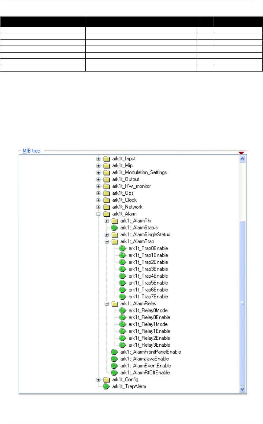
Screen Service SDT 501 UB-C ARK 1-T Operations
May, 2010 v 1.0 Page 3 - 156
OID Name R/W Description
2000)
1.3.6.1.4.1.21678.188.12.6.2 ark1t_Month RW Month setting
1.3.6.1.4.1.21678.188.12.6.3 ark1t_Day RW Day setting
1.3.6.1.4.1.21678.188.12.6.4 ark1t_Hour RW Hour setting
1.3.6.1.4.1.21678.188.12.6.5 ark1t_Minutes RW Minutes setting
1.3.6.1.4.1.21678.188.12.6.6 ark1t_Seconds RW Seconds setting
1.3.6.1.4.1.21678.188.13 ark1t_TrapAlarm Alarm
3.16 Configuring alarms MASKS
The ark1c_Alarm leaf allows the monitoring of alarms status, the setting of alarm masks and
thresholds.
Use alarm masks to select how and which alarm have to be notified.
Figure 28. Configuring alarms

Screen Service SDT 501 UB-C ARK 1-T Operations
May, 2010 v 1.0 Page 3 - 157
There are six families of alarm masks:
• ARK1r_AlarmJavaEnable: the selected alarms status is notified on the Java
alarm page icon.
• ARK1r_AlarmFrontPanelEnable: the selected alarms status is notified on
LCD display lighting the alarm button and listing the alarms in the Alarms menu
(refer to Alarms Menu paragraph).
• ARK1r_AlarmEventsEnable: the selected alarms status generate an alarm
event that will be logged in the event memory (refer to Events paragraph).
• ARK1r_AlarmRelay: the selected alarms switch-on the corresponding relay.
• ARK1r_AlarmTrap: the selected alarms generate the corresponding trap
message.
• ARK1r_AlarmRfEnable: the selected alarms switch off the RF output. The RF
mask is almost entirely fixed in order to avoid board damages or
malfunctioning.
Each alarm mask is a 32 bits word and each alarm represents one bit (0: Off, 1: On). Set the
decimal value corresponding to the mask you want to activate in the relative leaf. The
following table shows the bit-to-alarm association.
Table 18.
Bit-to-alarm association map
Alarm Bit Alarm Bit
Up converter Osc. Unlock 0 Signal 10 MHz Lock 16
PS Voltage out range 1 Signal 120 MHz Lock 17
PS Current out of range 2 Signal 960 MHz Lock 18
Absolute Power Limiter 3 Input Not Valid Alarm 19
Communication error 4 Late MIP Alarm 20
Temperature High Alarm 5 Network delay Alarm 21
Temperature Level-3dB 6 File System Error 22
Temperature High Warning 7 Bad File in File system 23
Forward Power High 8 DVB-T 1PPS Lock 24
Forward Power Low Warning 9 DVB-T PPS Phase 25
Forward Power Low Alarm 10 DVB-T System Delay 26
Reflex Power High 11 DVB-T No MIP 27
Fan Speed 12 No Input 28
Input Not Present Alarm 13 FPGA Boot alarm 29
GPS Lock 14 Warm up alarm 30
GPS Communication Error 15 Input Not Valid Alarm 31
E.g. if you want to enable the No MIP and No Input alarms of a generic alarm mask, set the
decimal value of 805,306,368 that corresponds to a binary value of
0011 0000 0000 0000 0000 0000 0000 0000.

Screen Service SDT 501 UB-C ARK 1-T Operations
May, 2010 v 1.0 Page 3 - 158
3.17 Traps
While a management station can poll, at fixed time interval, all the agents it knows for some
key information, each agent is responsible for notifying the management station of any alarm
condition. These events are communicated in SNMP messages known as traps.
The following parameters should be set in order to correctly configure traps:
• SNMP Agent Port: 162.
• SNMP Agent Transport protocol: IP/UDP.
• Variable
o OID: 1.3.6.1.4.1.21678.188.13.
o Value(gauge): 32 Bit
3.17.1 Configuring traps
Use Java (refer to Network and Alarms paragraphs for further information) or SNMP user
interfaces to configure traps.
The configuration of traps is performed through the setting of a trap alarm mask, by means
of leaves housed in the ARK1t_AlarmTrap node (refer to Configuring alarms paragraph), and
through the setting of the destination IP Address of the receiving management stations, by
means of leaves housed in the ARK1t_Network node as shown in next figure.
Figure 29. Configuring traps
Figure 30. SNMP Trap Message

Screen Service SDT 501 UB-C ARK 1-T Operations
May, 2010 v 1.0 Page 3 - 159

Screen Service SDT 501 UB-C ARK 1-T Operations
May, 2010 v 1.0 Page 3 - 160
Each trap carries a 32 bits word in which each alarm represents one bit (0: Off, 1: On). The
following table shows the bit-to-alarm association.
Table 19.
Bit-to-trap association map
Alarm Bit Alarm Bit
Up converter Osc. Unlock 0 Signal 10 MHz Lock 16
PS Voltage out range 1 Signal 120 MHz Lock 17
PS Current out of range 2 Signal 960 MHz Lock 18
Absolute Power Limiter 3 Input Not Valid Alarm 19
Up converter communication error 4 Late MIP Alarm 20
Temperature High Alarm 5 Network Delay Alarm 21
Temperature Level-3dB 6 Not Used 22
Temperature High Warning 7 File System Error 23
Forward Power High 8 Bad File in File system 24
Forward Power Low Warning 9 1PPS Lock 25
Forward Power Low Alarm 10 PPS Phase 26
Reflex Power High 11 System Delay 27
Fan Speed 12 DVB-T No MIP 28
Input Not Present Alarm 13 No Input 29
GPS Lock 14 FPGA Boot alarm 30
GPS Communication Error 15 Warm Up 31
E.g. A trap carrying the decimal value 805,306,368, corresponding to a binary value of
0011 0000 0000 0000 0000 0000 0000 0000, means that DVB-T No MIP (bit 28) and No
Input (bit 29) alarms rose.
The Community shown in trap messages can be set from Java interface in the Community
box within the Network window (refer to Network paragraph).
box within the Network window (refer to Network paragraph).

Screen Service SDT 501 UB-C ARK 1-T Operations
May, 2010 v 1.0 Page 3 - 161
Appendix A. Seamless input switching
The Ark1-T device provides the functionality of seamless input auto-switching. This switching
occurs between primary and secondary input selected, under the following restrictions:
• The device is working in SFN mode;
• The frequency reference selected is external or GPS;
• The two inputs are both ASI, and contain the identical stream.
Under these conditions, when primary input becomes not locked, the device automatically
switches to the secondary input. No errors in synchronism bytes or in continuity counters can
be observed in output transport stream. If primary input became locked again, the device
would automatically switch to the primary input, with no errors in synchronism or in continuity
counter.
At the status of the art this functionality is implemented only for ASI inputs, so in Java or
SNMP interface only ASI inputs can be selected as secondary input. The SFN mode with
external frequency reference is required in order to allow the device to achieve the
synchronism.
synchronism.

Screen Service SDT 501 UB-C ARK 1-T Operations
May, 2010 v 1.0 Page 3 - 162
Appendix B. Standalone/Driver working modes
Two different working modes are provided:
• Stand-alone: the device works in stand-alone mode. The system configuration can
be totally set through user interfaces. Pre-correction curves are automatically
selected according to channel and power range.
• Driver: the device works in a driven system. The system configuration cannot be
totally set through user interfaces. Some settings are disabled on the user interfaces
in order to be driven by serial interface commands. Pre-correction curves are not
automatically selected according to channel and power range, but the selection is
manually performed through serial interface commands.
The following table lists the commands, specific to each system interface, which must be
enabled or disabled while working in Driver mode.
Note: Diver mode is a specific working mode available and used only in N+1 configuration
systems.
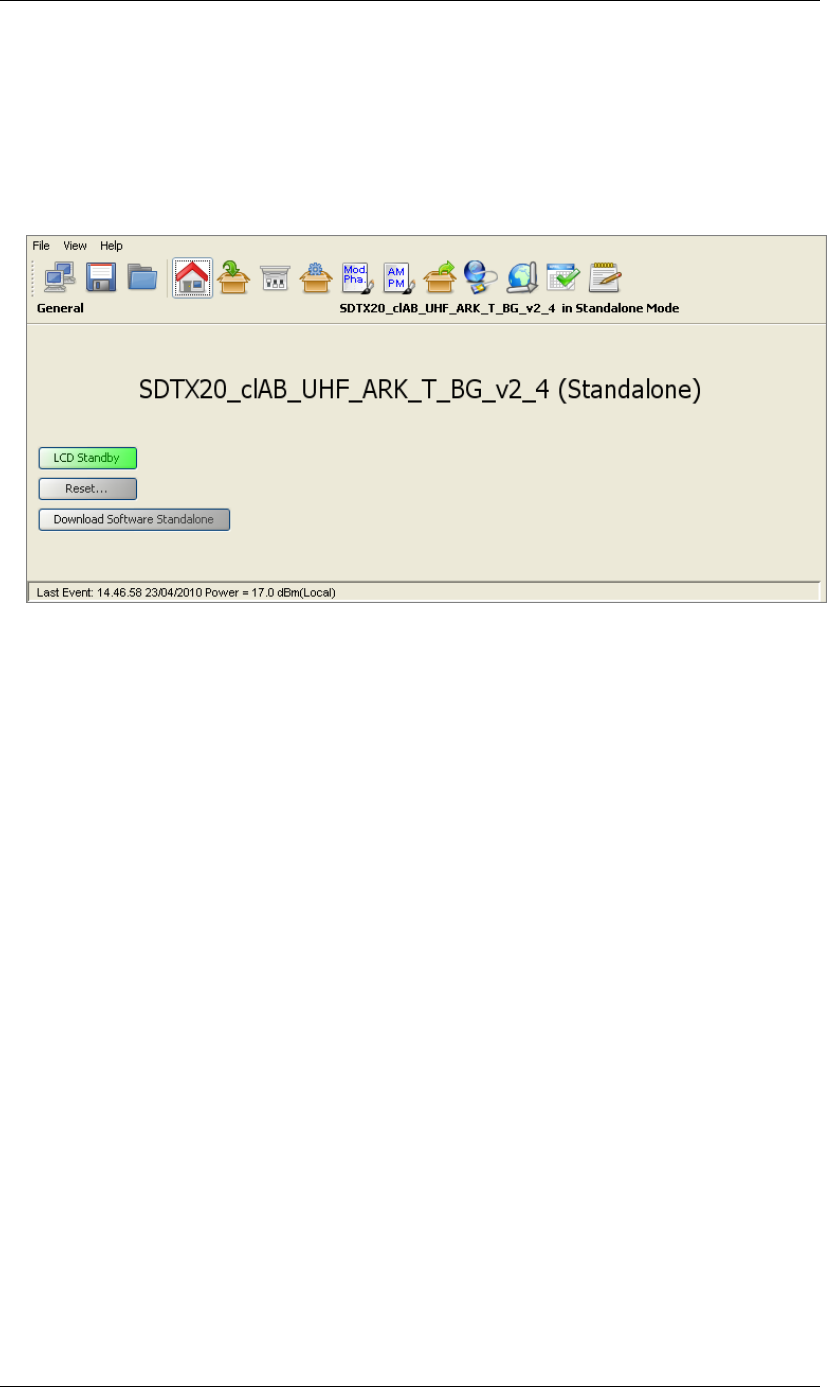
Screen Service SDT 501 UB-C ARK 1-T Operations
May, 2010 v 1.0 Page 3 - 163
Appendix C. Installer Definitions feature
The various Installer Definitions allows to support some different transmission standard
definition, different working mode, power supply and power output
in the first page of java interface are showed name and version of installer definition
Following table explain the feature of each Installer Definitions

Screen Service SDT 501 UB-C ARK 1-T Operations
May, 2010 v 1.0 Page 3 - 164
Appendix D. Transport-level Protocols
ARK 1 device allows connections over different ports and using different transport protocols
over Gigabit Ethernet depending on functions and operations.
In the following table used ports and protocols are listed to help users understand what
software functions allow multiple connections and which port must be enabled.
E.g. pre-correction curves editing and files updating operations open and keep busy the
connection to port 5000 till the connection releasing. The connection to this port precludes
the possibility of multiple connections and of programming the device.
Table 20. Transport-level Protocols
Port Protocol Application Multiple connections
10001 TCP Management Yes
TCP Updating Not
5000
TCP Pre-correction curves Not
161 UDP SNMP Yes
162 UDP SNMP Trap management Yes
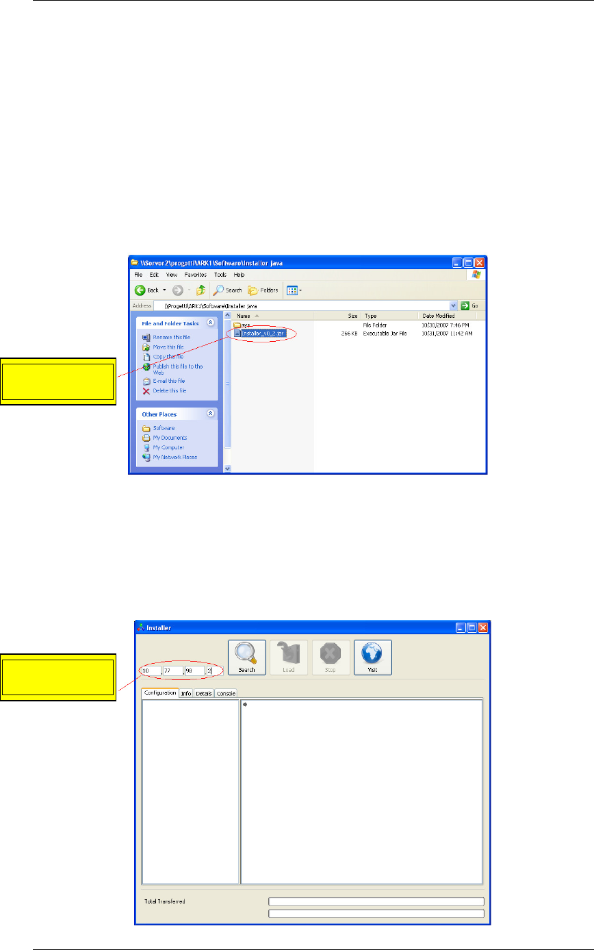
Screen Service SDT 501 UB-C ARK 1-T Operations
May, 2010 v 1.0 Page 3 - 165
Appendix E. Application Note
Screenshots of this application note are used as an example and shown file names are not
related to ARK1-T device.
E.1 How to update by installer
1. Launch the Java installer.
Figure 31. Java Installer
2. Insert the board IP address into the numeric field.
Figure 32. Java Installer -
IP Address insertion
Insert the board
IP Address
Launch the
Java Installer
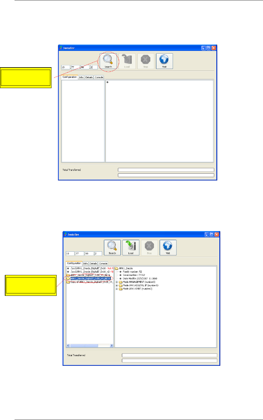
Screen Service SDT 501 UB-C ARK 1-T Operations
May, 2010 v 1.0 Page 3 - 166
3. Click on the “Search” button.
Figure 33. Java Installer
-
Search button
4. Select the device version you want to load.
Figure 34. Java Installer - Device Version Selection
Click on the
“Search” button
Select the
version
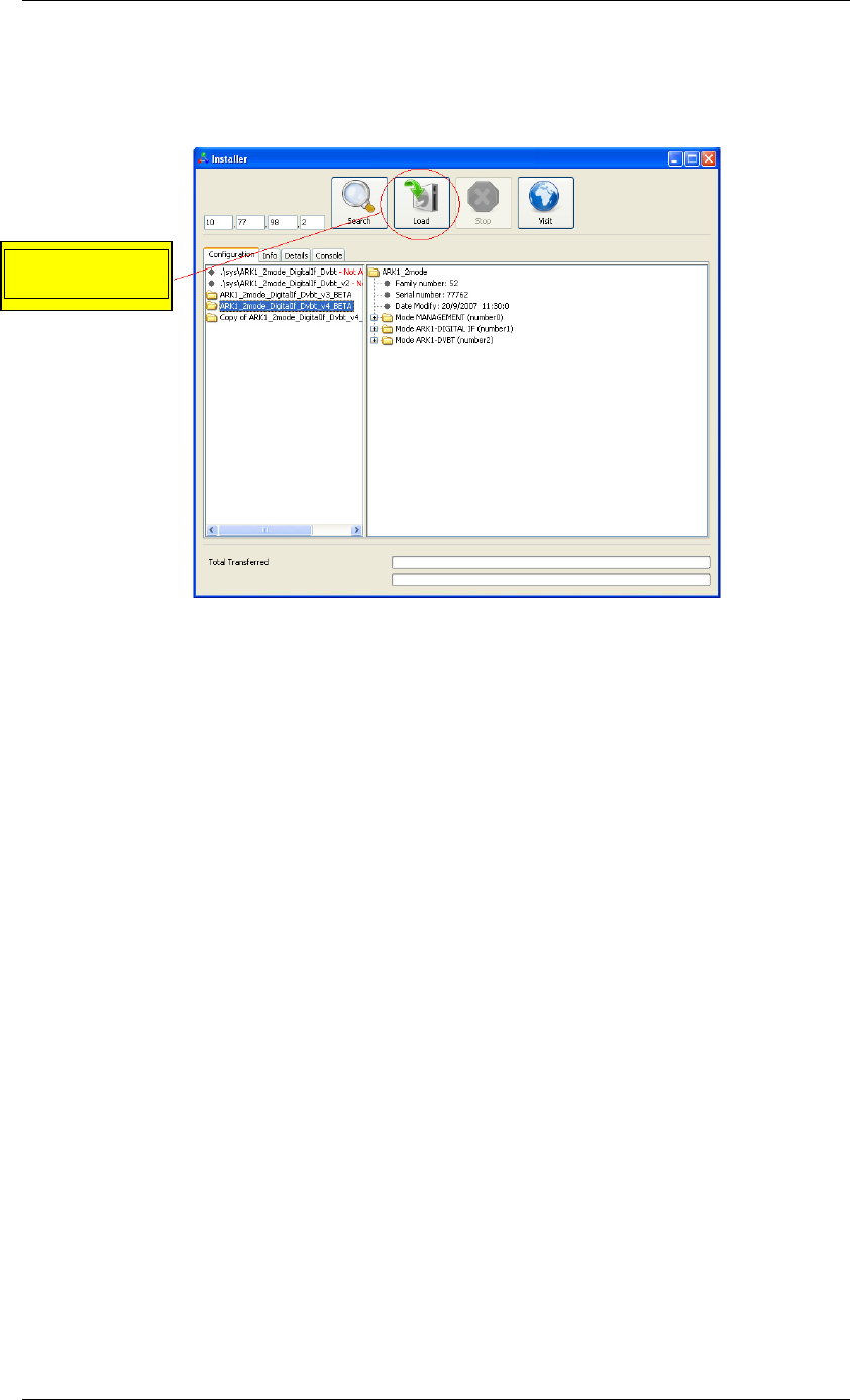
Screen Service SDT 501 UB-C ARK 1-T Operations
May, 2010 v 1.0 Page 3 - 167
5. Click on the “Load” button.
Figure 35. Java Installer - Load button
Click on the
“Load” button
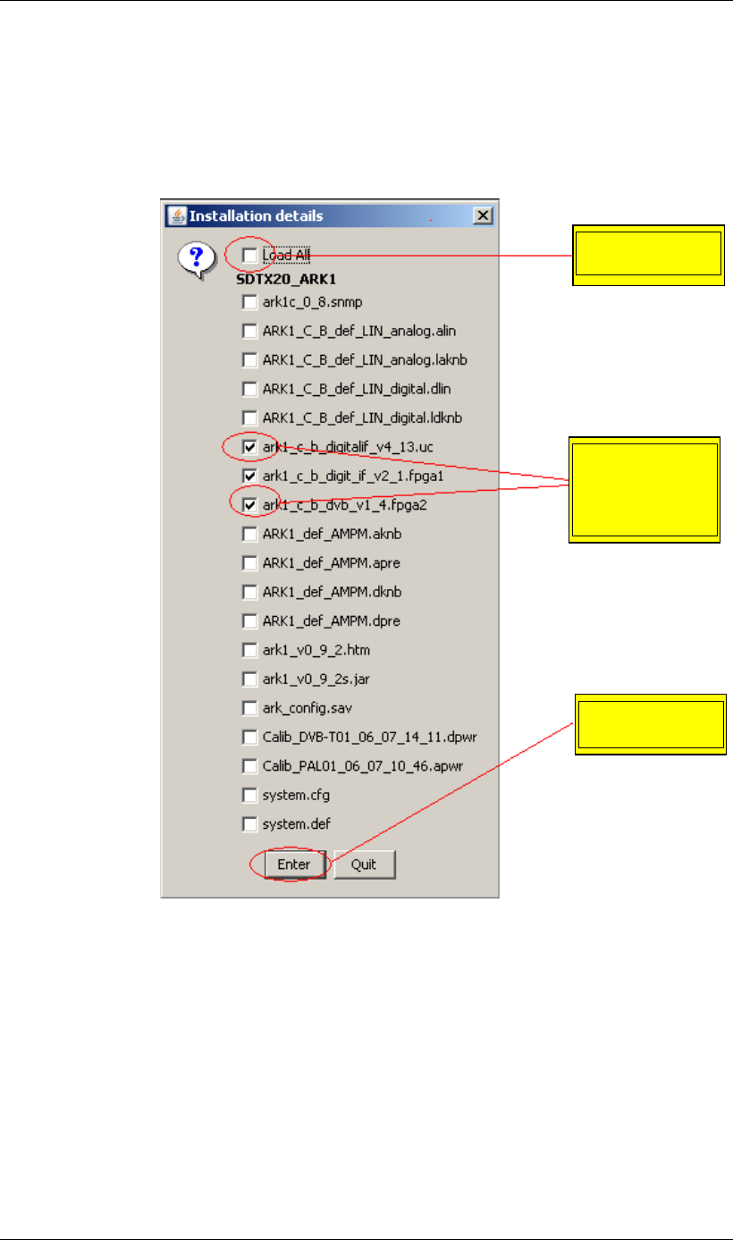
Screen Service SDT 501 UB-C ARK 1-T Operations
May, 2010 v 1.0 Page 3 - 168
6. If you want to update only some software versions, click on the check boxes
corresponding to the software version you want to load, otherwise click on the check
box corresponding to the Load All option. Click on the “Enter” button to start the
loading.
Figure 36. Java Installer - Software versions selection
Select the
“Load All” option
Select one by
one the software
versions you
want to load
Click on the
“Enter” button
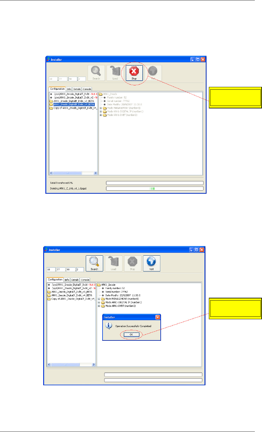
Screen Service SDT 501 UB-C ARK 1-T Operations
May, 2010 v 1.0 Page 3 - 169
7. Once started the loading, the “Stop” button lights up. Click on this button to end the
programming.
Figure 37. Java Installer - Stop button
8. When the loading is complete, the pop-up window “Operation Successfully
Completed” appears. Click on the “OK” button.
Figure 38. Java Installer - Operation Successfully Completed
Click on the
“Stop” button
Click on the
“OK” button
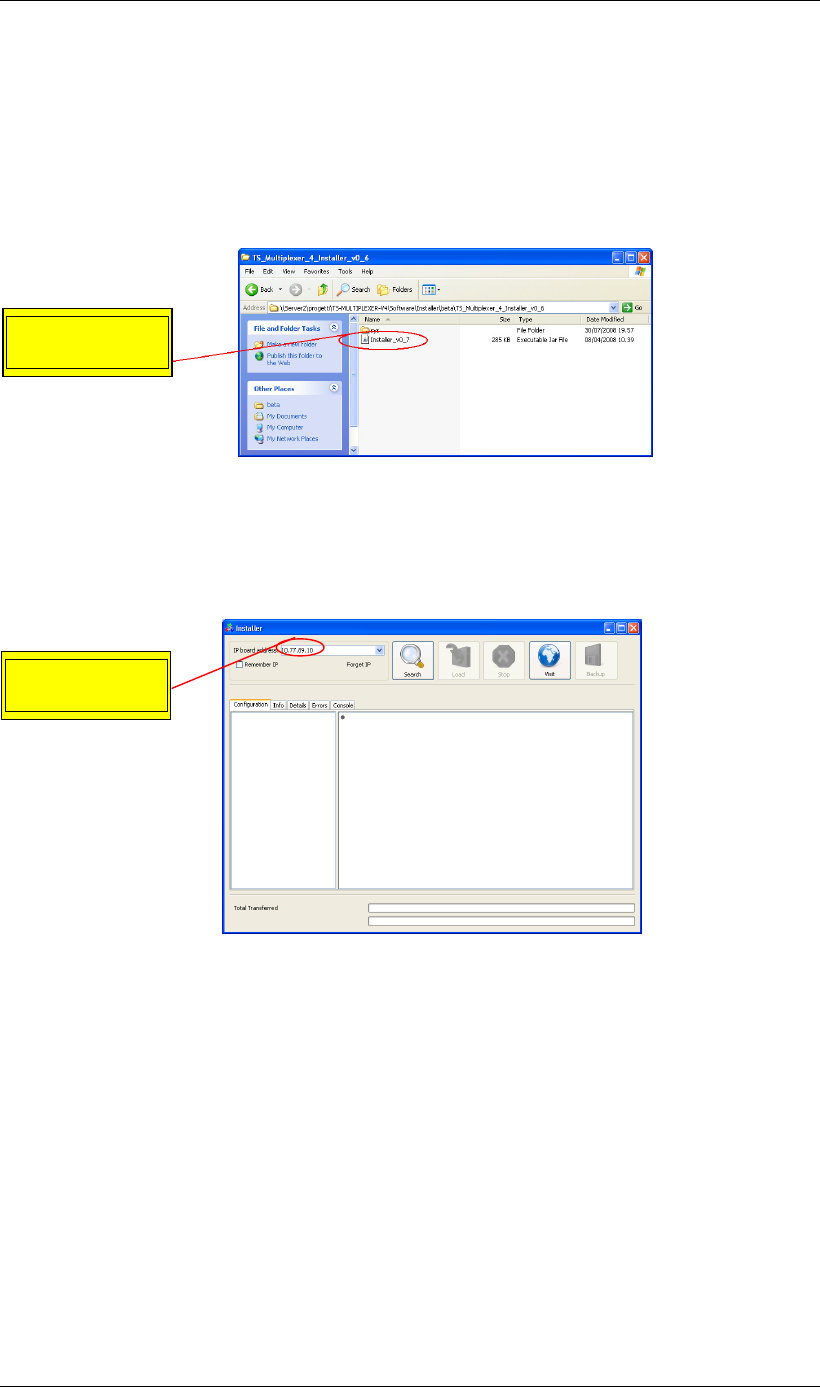
Screen Service SDT 501 UB-C ARK 1-T Operations
May, 2010 v 1.0 Page 3 - 170
E.2 How to backup by installer
1. Launch the Java installer.
Figure 39. Java Installer
2. Insert the board IP address into the numeric field.
Figure 40. Java Installer -
IP Address insertion
Insert the board
IP Address
Launch the
Java Installer

Screen Service SDT 501 UB-C ARK 1-T Operations
May, 2010 v 1.0 Page 3 - 171
1. Click on the “Search” button.
Figure 41. Java Installer
-
Search button
2. Click on the “Backup” button.
Figure 42. Java Installer – Backup button
Click on the
“Search” button
Click on the
“Backup” button
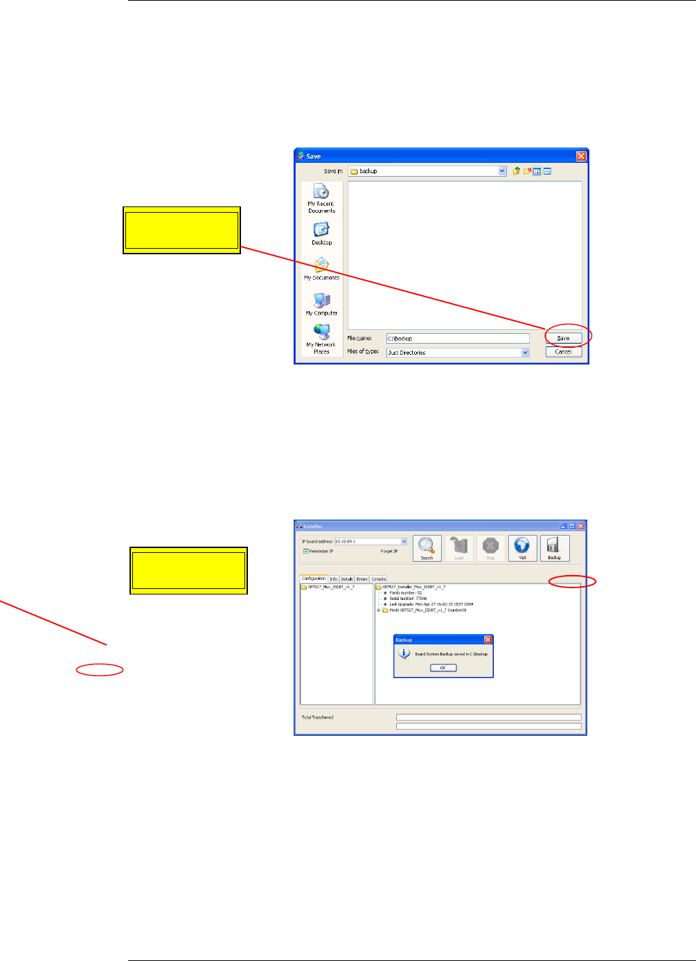
Screen Service SDT 501 UB-C ARK 1-T Operations
May, 2010 v 1.0 Page 3 - 172
3. Select an existing destination folder and click on the “Save” button.
Figure 43. Java Installer – Save button
4. When the backup is complete, the pop-up window “Board System Backup saved in
Destination Folder” appears. Click on the “OK” button.
Figure 44. Java Installer - Operation Successfully Completed
Click on the
“Save” button
Click on the
“OK” button
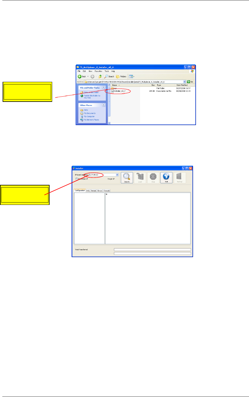
Screen Service SDT 501 UB-C ARK 1-T Operations
May, 2010 v 1.0 Page 3 - 173
E.3 How to open the Java User Interface by installer
1. Launch the Java installer.
Figure 45. Java Installer
2. Insert the board IP address into the numeric field.
Figure 46. Java Installer -
IP Address insertion
Insert the board
IP Address
Launch the
Java Installer
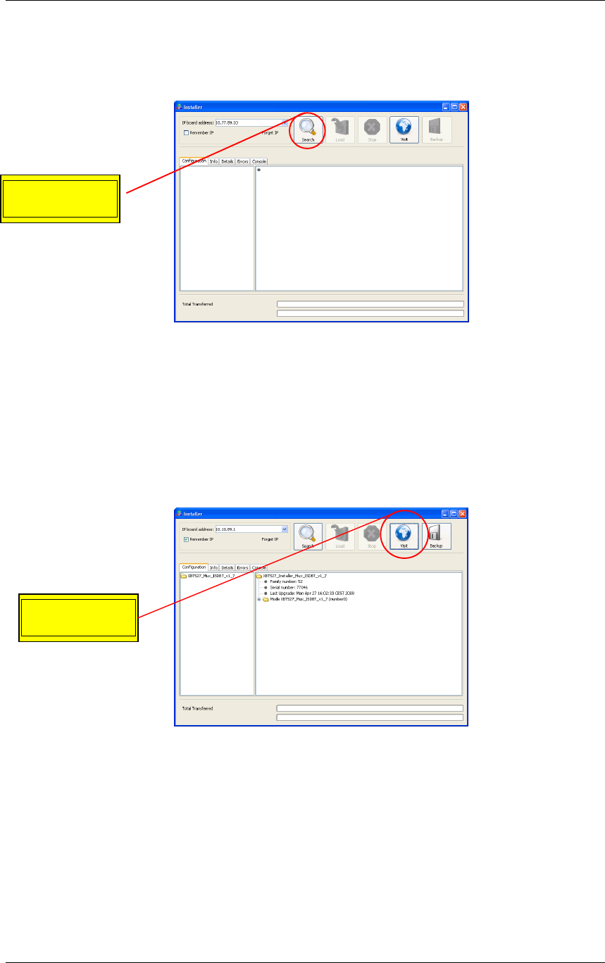
Screen Service SDT 501 UB-C ARK 1-T Operations
May, 2010 v 1.0 Page 3 - 174
3. Click on the “Search” button.
Figure 47. Java Installer
-
Search button
4. Click on the “Visit” button.
Figure 48. Java Installer – Visit button
Click on the
“Visit” button
Click on the
“Search” button

Screen Service SDT 501 UB-C ARK 1-T Operations
May, 2010 v 1.0 Page 3 - 175
5. The Java User Interface will open automatically.
Figure 49. Java User Interface – General window

Screen Service SDT 501 UB-C ARK 1-T Operations
May, 2010 v 1.0 Page 3 - 176
Appendix F. Java Virtual Machine
The Java interface requires a host computer connected via Ethernet to the board with the proper
Java Machine version installed.
F.1 Ethernet connection
The host computer has to be connected via Ethernet to the board.
Direct or crossed UTP category 6 cable is recommended.
NOTE: for best performances, a fast connection (i.e. gigabit Ethernet) is required. After careful
testing it was found that a slow connection makes using the AM/PM tool difficult.
F.1.1 Configuration
In order to connect to the board trough a LAN, all the devices have to be on the same network.
The default IP address settings of the X-port are:
• IP address: 10.77.xx.xx , where xx is the host address unique for each board.
• Subnet mask: 255.255.0.0 .
Remember to change these settings if they are not compatible with the LAN where the computer
and the board are connected.
IP address and network parameters can be changed only using the local interface. Please refer
to chapter 6 for the network setting commands.
F.2 Java(TM) Platform
F.2.1 Download
The Java Interface works with any Sun Java Virtual Machine after the 1.4.1 version.
If the computer has no Java Virtual Machine installed, the recommended 1.5.0 version can be
downloaded from the Sun Server trough this link:
http://www.java.com/.
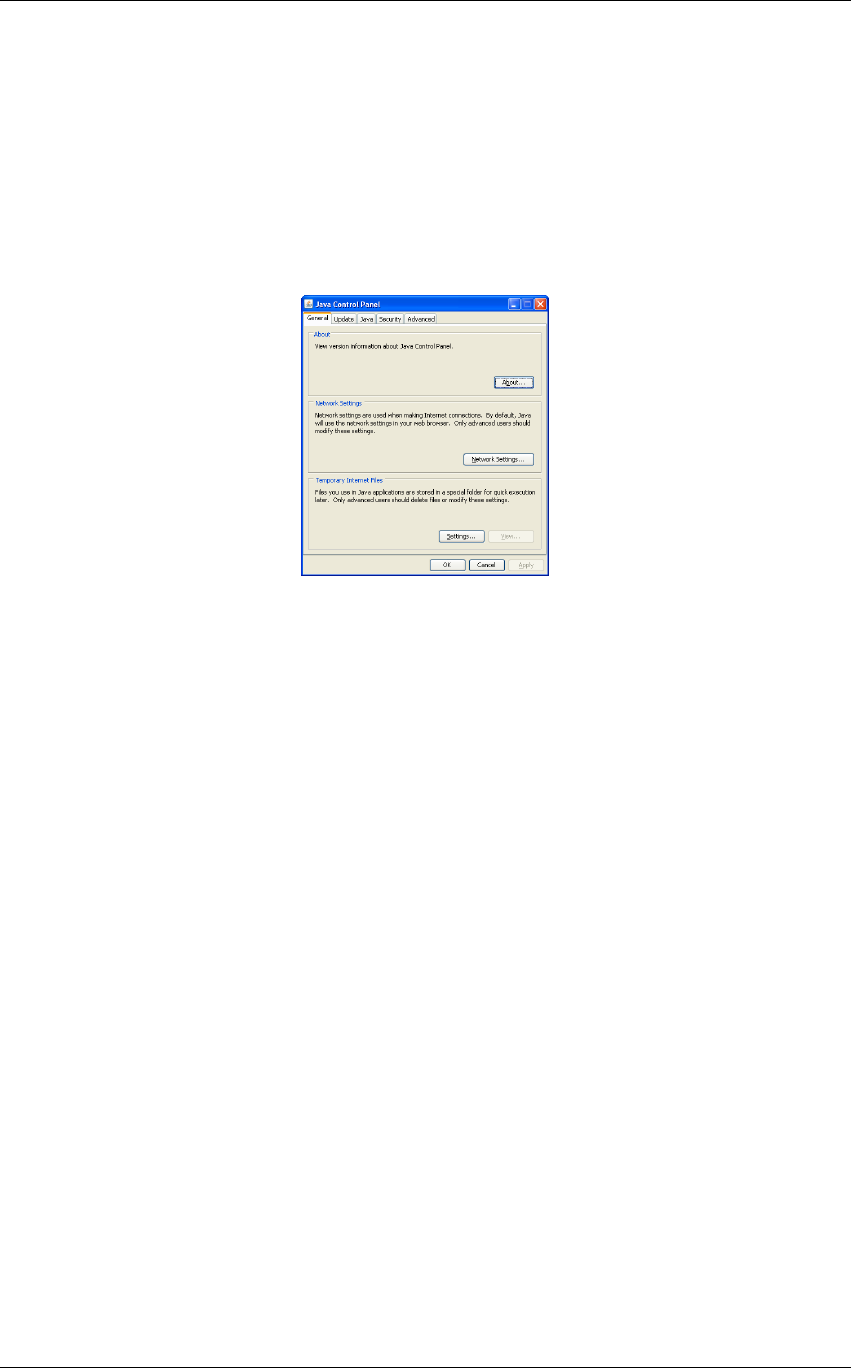
Screen Service SDT 501 UB-C ARK 1-T Operations
May, 2010 v 1.0 Page 3 - 177
F.2.2 Java Control Panel
Java caching must be disabled; to do that follow the following steps:
1. Open the PC general Control Panel and enter in the Java Control Panel
2. The following window will suddenly appear.
Figure 50. Java Control Panel
3. Select “Settings…” in the “Temporary Internet Files” section of the “General” tab.

Screen Service SDT 501 UB-C ARK 1-T Operations
May, 2010 v 1.0 Page 3 - 178
4. Deselect the check box of the “Keep temporary files on my computer” (disable cache).
Figure 51. Temporary Files Settings
5. Push “OK” button and close the window.
F.3 Supported Web Browsers
The Java GUI is designed to support every Web Browser that uses Sun Java Virtual Machine
from 1.4.1 and newer.
Here’s a list of Web Browsers where Java GUI has been tested and troubleshot:
• Microsoft Internet Explorer, version 5 and newer.
• Mozilla Firefox, version 1.5 and newer.
3.18 AUTOMATIC FREQUENCY CONTROL
The Television Broadcasting through countrywide transposers networks requires special care to
avoid too high frequency drift errors.
The Automatic Frequency Control is highly recommended for transposers chains. The following
figure illustrates an example of when the AFC might be used to stop the overwhelming increase
of such errors.
Figure 52. TROVA NOME

Screen Service SDT 501 UB-C ARK 1-T Operations
May, 2010 v 1.0 Page 3 - 179
The Automatic Frequency Control in ARK1 devices is software defined.
Most of the frequency drift errors could be avoided by means of a stable frequency reference,
such as GPS, but since it is not always available, the ARK1 AFC makes it possible to
compensate frequency jitters owing to each previous transposer.
Frequency compensation of analog input signals is performed through a proprietary algorithm
that, filtering the input video carrier, allows the control loop to extract frequency jitter information
from the input RF phase deviation.
The frequency error adjustment slows down within 3 Hz; it takes about 2 minutes to fulfil the
correction.
• Frequency resolution: ±1Hz.
Maximum frequency compensation: ±4,000,000 Hz.
Frequency compensation of digital input signals is carried out through frequency jitter
information coming from STV0362 receiving the HP Transport Stream.
• Frequency resolution: ±1kHz.
• Maximum frequency compensation: ±83kHz.
Due to the Symbol Rate error compensation of the frequency measure algorithm of STV, digital
AFC can work properly only with 0ppm Symbol Rate errors in the input signal.
D
C
A
TX
B
CH 22
CH 22
CH 60: X
CH 36
CH 60: X
CH 36
CH 40
Transposer
Transposer
Teansposer
E
CH 21
Transposer
CH 40
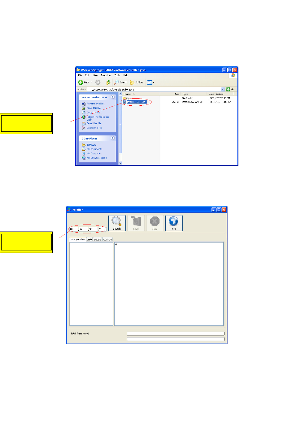
Screen Service SDT 501 UB-C ARK 1-T Operations
May, 2010 v 1.0 Page 3 - 180
3.19 APPLICATION NOTE
3.19.1 How to update
9. Launch the Java installer.
Figure 53. Java Installer
10. Insert the board IP address into the numeric field.
Figure 54. Java Installer -
IP Address insertion
Insert the board
IP Address
Launch the
Java Installer
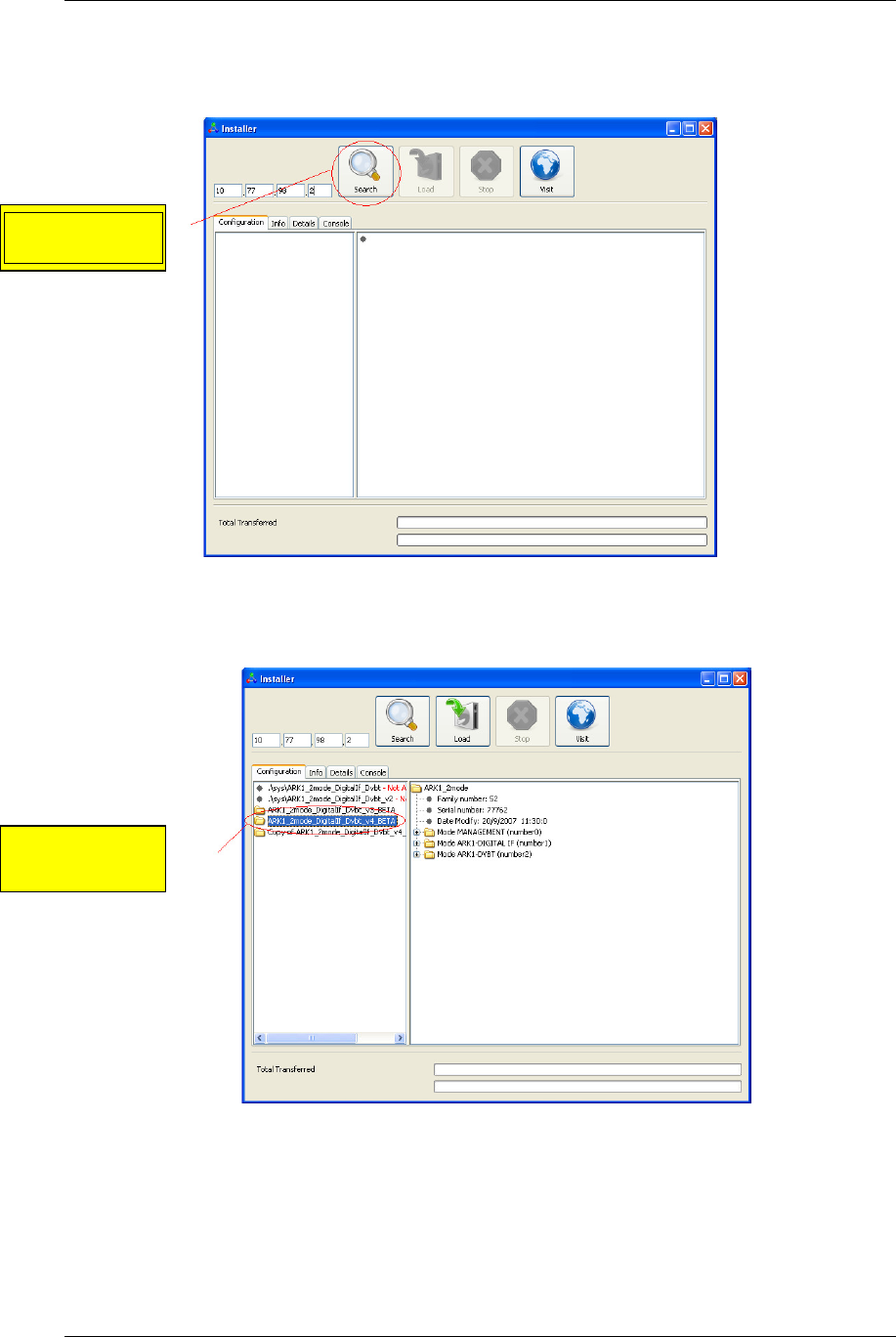
Screen Service SDT 501 UB-C ARK 1-T Operations
May, 2010 v 1.0 Page 3 - 181
11. Click on the “Search” button.
Figure 55. Java Installer
-
Search button
12. Select the device version you want to load.
Figure 56. Java Installer - Device Version Selection
Click on the
“Search” button
Select the
version
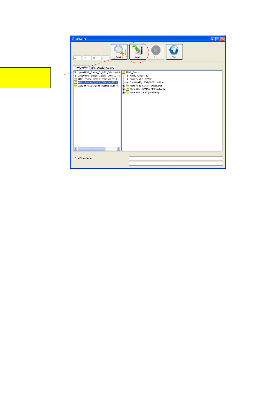
Screen Service SDT 501 UB-C ARK 1-T Operations
May, 2010 v 1.0 Page 3 - 182
13. Click on the “Load” button.
Figure 57. Java Installer - Load button
Click on the
“Load” button
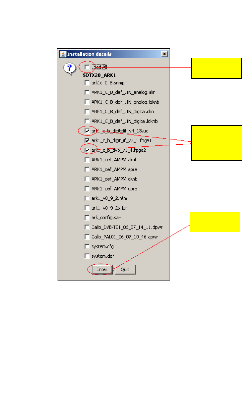
Screen Service SDT 501 UB-C ARK 1-T Operations
May, 2010 v 1.0 Page 3 - 183
14. If you want to update only some software versions, click on the check boxes
corresponding to the software version you want to load, otherwise click on the check
box corresponding to the Load All option. Click on the “Enter” button to start the loading.
Figure 58. Java Installer - Software versions selection
Select the
“Load All” option
Select one by
one the software
versions you
want to load
Click on the
“Enter” button

Screen Service SDT 501 UB-C ARK 1-T Operations
May, 2010 v 1.0 Page 3 - 184
15. Once started the loading, the “Stop” button lights up. Click on this button to end the
programming.
Figure 59. Java Installer - Stop button
16. When the loading is complete, the pop-up window “Operation Successfully Completed”
appears. Click on the “OK” button.
Figure 60. Java Installer - Operation Successfully Completed
Click on the
“Stop” button
Click on the
“OK” button

Screen Service SDT 501 UB-C ARK 1-T Operations
May, 2010 v 1.0 Page 3 - 185
3.20 Java Virtual Machine
The Java interface requires a host computer connected via Ethernet to the board with the proper
Java Machine version installed.
3.21 ETHERNET CONNECTION
The host computer has to be connected via Ethernet to the board.
Direct or crossed UTP category 6 cable is recommended.
3.21.1 Configuration
In order to connect to the board trough a LAN, all the devices have to be on the same network.
The default IP address settings of the X-port are:
• IP address: 10.77.xx.xx , where xx is the host address unique for each board.
• Subnet mask: 255.255.0.0 .
Remember to change these settings if they are not compatible with the LAN where the computer
and the board are connected.
IP address and network parameters can be changed only using the local interface. Please refer
to chapter 6 for the network setting commands.
3.21.2 Java(TM) Platform
3.21.3 Download
The Java Interface works with any Sun Java Virtual Machine after the 1.4.1 version.
If the computer has no Java Virtual Machine installed, the recommended 1.5.0 version can be
downloaded from the Sun Server trough this link:
http://www.java.com/.
3.21.4 Java Control Panel
Java caching must be disabled; to do that follow the following steps:
1. Open Internet Explorer, click on Tool button and select the Sun Java Console option.
Figure 61. Sun Java Console
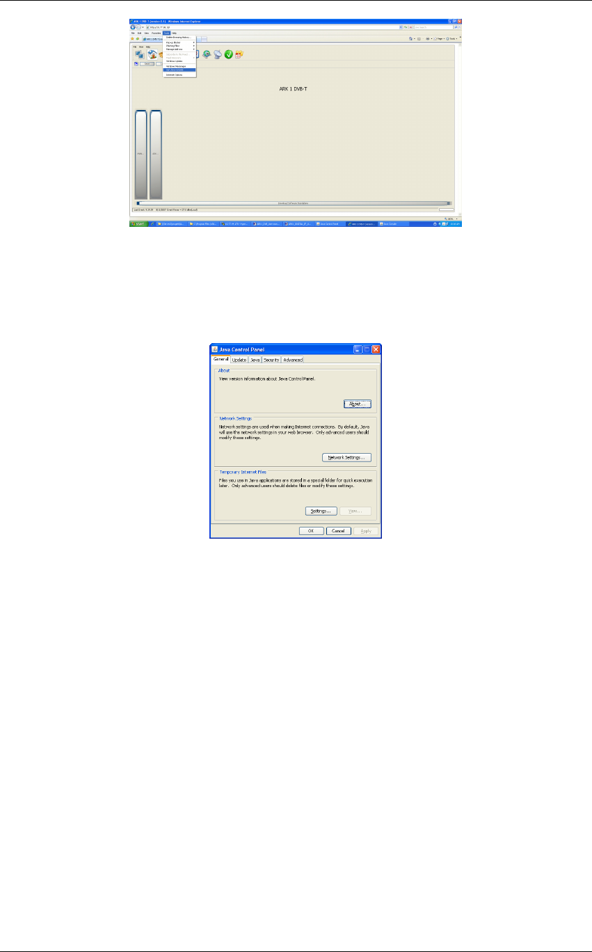
Screen Service SDT 501 UB-C ARK 1-T Operations
May, 2010 v 1.0 Page 3 - 186
2. Perform a right button mouse click on the Java(TM) Platform icon sited on the right
corner of the Taskbar and select “Open Control Panel”. The following window will
suddenly appear.
Figure 62. Java Control Panel
3. Select “Settings…” in the “Temporary Internet Files” section of the “General” tab.

Screen Service SDT 501 UB-C ARK 1-T Operations
May, 2010 v 1.0 Page 3 - 187
4. Deselect the check box of the “Keep temporary files on my computer” (disable cache).
Figure 63. Temporary Files Settings
5. Push “OK” button and close the window.
3.22 SUPPORTED WEB BROWSERS
The Java GUI is designed to support every Web Browser that uses Sun Java Virtual Machine
from 1.4.1 and newer.
Here’s a list of Web Browsers where Java GUI has been tested and troubleshot:
• Microsoft Internet Explorer, version 5 and newer.
• Mozilla Firefox, version 1.5 and newer.
3.23 SECURITY measures and systems used with the transmitter to
make sure that only legal copies of the software can be loaded
on the transmitter
The equipment can operate only with legal software released by SCREEN SERVICE.
Infact the firmware has been designed following certain software nomenclature and codes.
Other software, illegally loaded, will produce the BOOT ERROR at the switch on and then the
eqipment stops.
It is worth to remind that the upgrading procedure foresees the use of a DEVICE INSTALLER which
uses PROPIETARY PROTOCOL as well.