Screen Service Broadcasting Technologies SDTX-ARK1 20 Watt Multimode SDR Transmitter User Manual
Screen Service Broadcasting Technologies SpA 20 Watt Multimode SDR Transmitter
UserManual.wiki
>
Screen Service Broadcasting Technologies
>
SDTX ARK1 User Manual
User Manual Revised
Navigation menu
Upload a User Manual
Namespaces
Wiki Guide
HTML
PDF
Info
Views
User Manual
Discussion / Help
Navigation
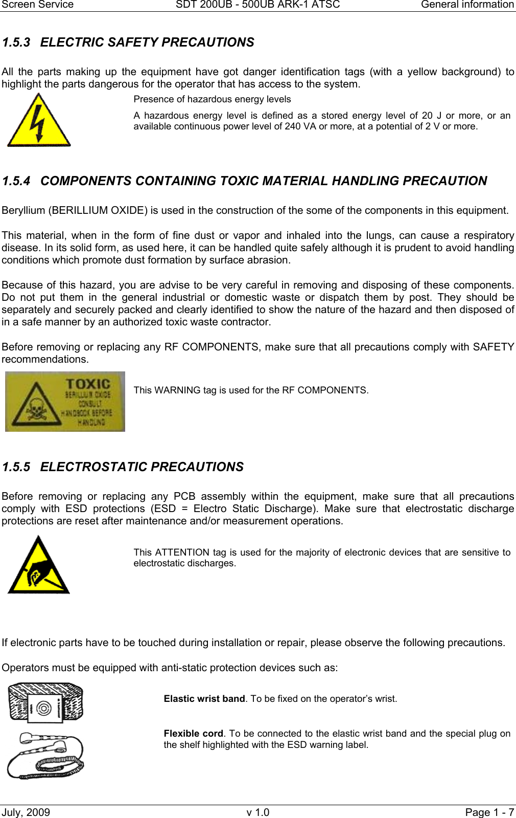

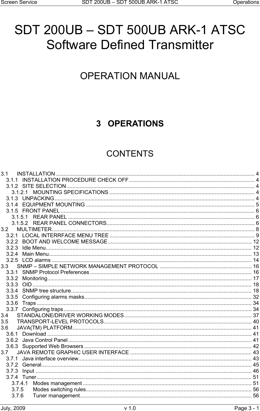
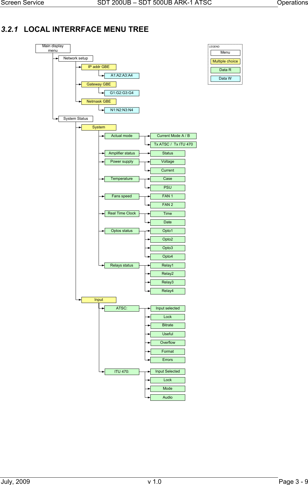
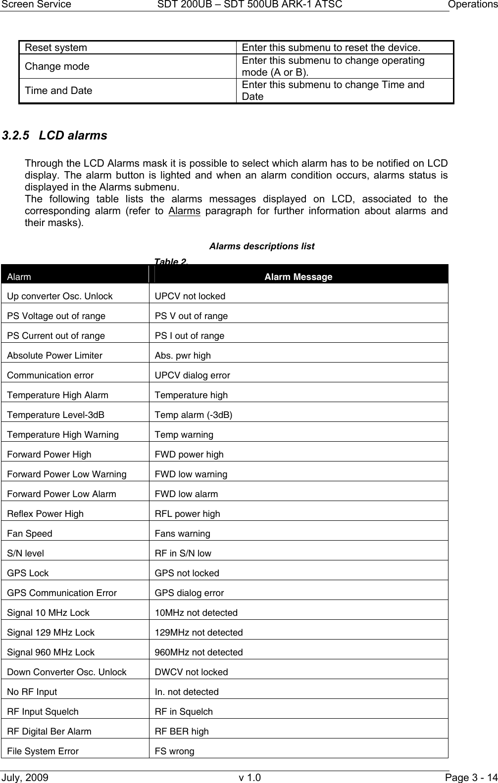
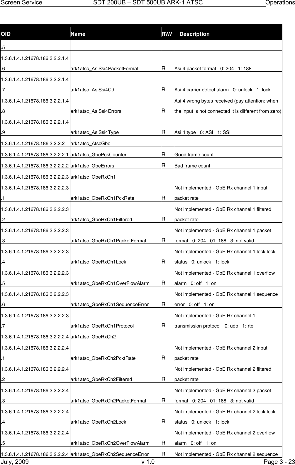
![Screen Service SDT 200UB – SDT 500UB ARK-1 ATSC Operations July, 2009 v 1.0 Page 3 - 12 3.2.2 BOOT AND WELCOME MESSAGE Turning on the equipment, the display shows the progress bar as follow: When the boot is over, the board is ready. Press ESC to enter the main menu, otherwise after one minute waiting the idle status message appears. 3.2.3 Idle Menu This menu appears after one minute waiting from the last touch. Information contained in the Idle Menu are described in next table. Screen ServiceARK - ATSC/ITU.470Up Converter check Init : [ ] Wait Screen ServiceARK - ATSC/ITU.470 System Init Init : [ ] Wait Screen ServiceARK - ATSC/ITU.470Boot FPGAInit : [ ] Wait Screen ServiceARK - ATSC/ITU.470 Up Converter check Init : [ ] Wait Screen ServiceARK - ATSC/ITU470 Start system Init : [ ] Ready Screen ServiceARK –ATSC/ITU.47010.77.104.4 Ready ARK –ITU 470 In: RTP1 Out 23.1dBm CH:22 UTC: 14:11 08/11/06 ARK -ATSC In: RTP1 Out 23.1dBm CH:22 UTC: 14:11 08/11/06](https://usermanual.wiki/Screen-Service-Broadcasting-Technologies/SDTX-ARK1/User-Guide-1525670-Page-34.png)
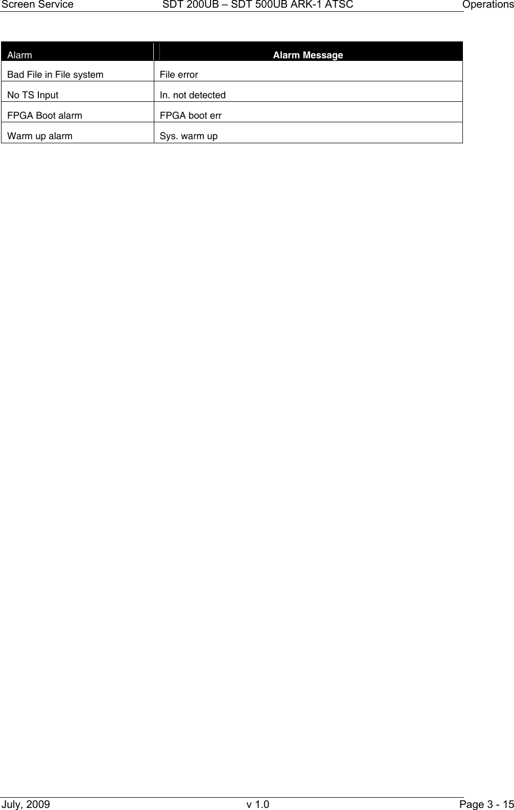
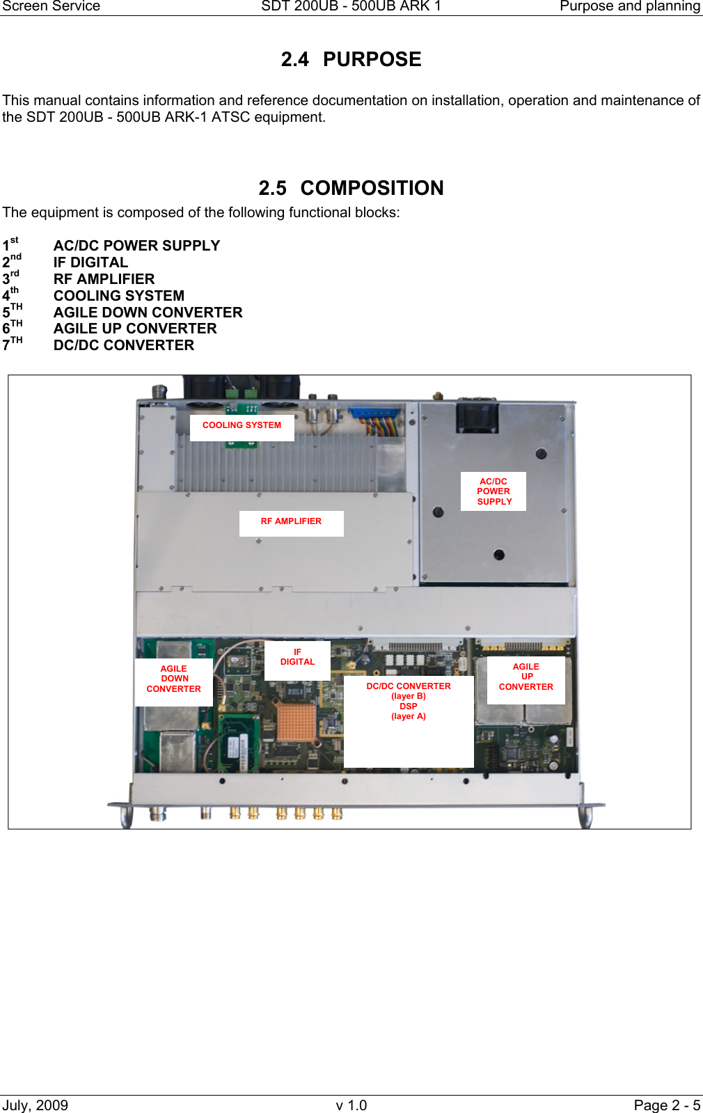
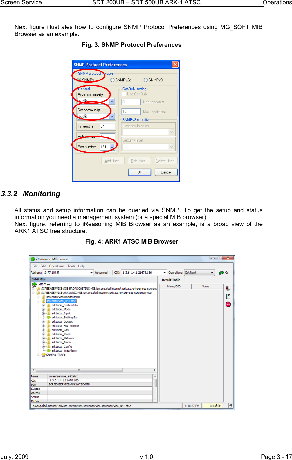
![Screen Service SDT 200UB – SDT 500UB ARK-1 ATSC Operations July, 2009 v 1.0 Page 3 - 16 3.3 SNMP – SIMPLE NETWORK MANAGEMENT PROTOCOL The SNMP model assumes the existence of managers and agents. A manager is a software module in a management system responsible for managing the device. An agent is a software module in a managed device responsible for maintaining local management information and delivering that information to a manager via SNMP. A management information exchange can be initiated by the manager (via polling) or by the agent (via trap). Interaction between a user of board management and the board management software takes place across a user interface. Such an interface is needed to provide users with a monitoring and controlling tool in order to allow some parameters to be viewed or set locally. The operations that are supported in SNMP network management are the alteration and inspection of variables. Specifically, three general-purpose operations may be performed on scalar objects: • Get: a management station retrieves a scalar object value from a managed station. • Set: a management station updates a scalar object value in a managed station. • Trap: a managed station sends an unsolicited scalar object value to a management station. Management information accessible via SNMP is maintained in a management information base (MIB) at each manager and agent node. On manager side, ARK1 ATSC management system has been tested with MG-SOFT as MIB Browser; besides compatibility with any other MIB browser is assured. The following MIB libraries are required for the SNMP management of the equipment: • SCREENSERVICE-SCB-BROADCASTING-MIB.my; • ark1atsc_0_6.MY. Compatibility tested and assured with SNMP version 1 and 2. 3.3.1 SNMP Protocol Preferences Go to SNMP Protocol Preferences. The following parameters should be set in order to correctly configure the SNMP Manager: • SNMP protocol version: SNMPv1; • Read Community: the same of the one set in the Get field of Java interface, community section; • Set Community: the same of the one set in the Set field of Java interface, community section; • Timeout [s]: user defined; • Retransmits: user defined; • Port number: 161.](https://usermanual.wiki/Screen-Service-Broadcasting-Technologies/SDTX-ARK1/User-Guide-1525670-Page-38.png)
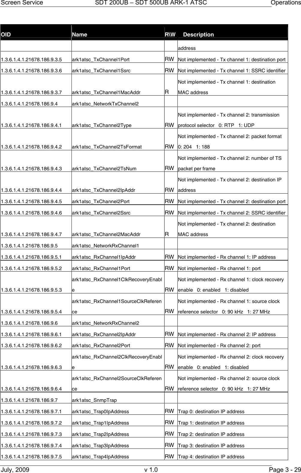
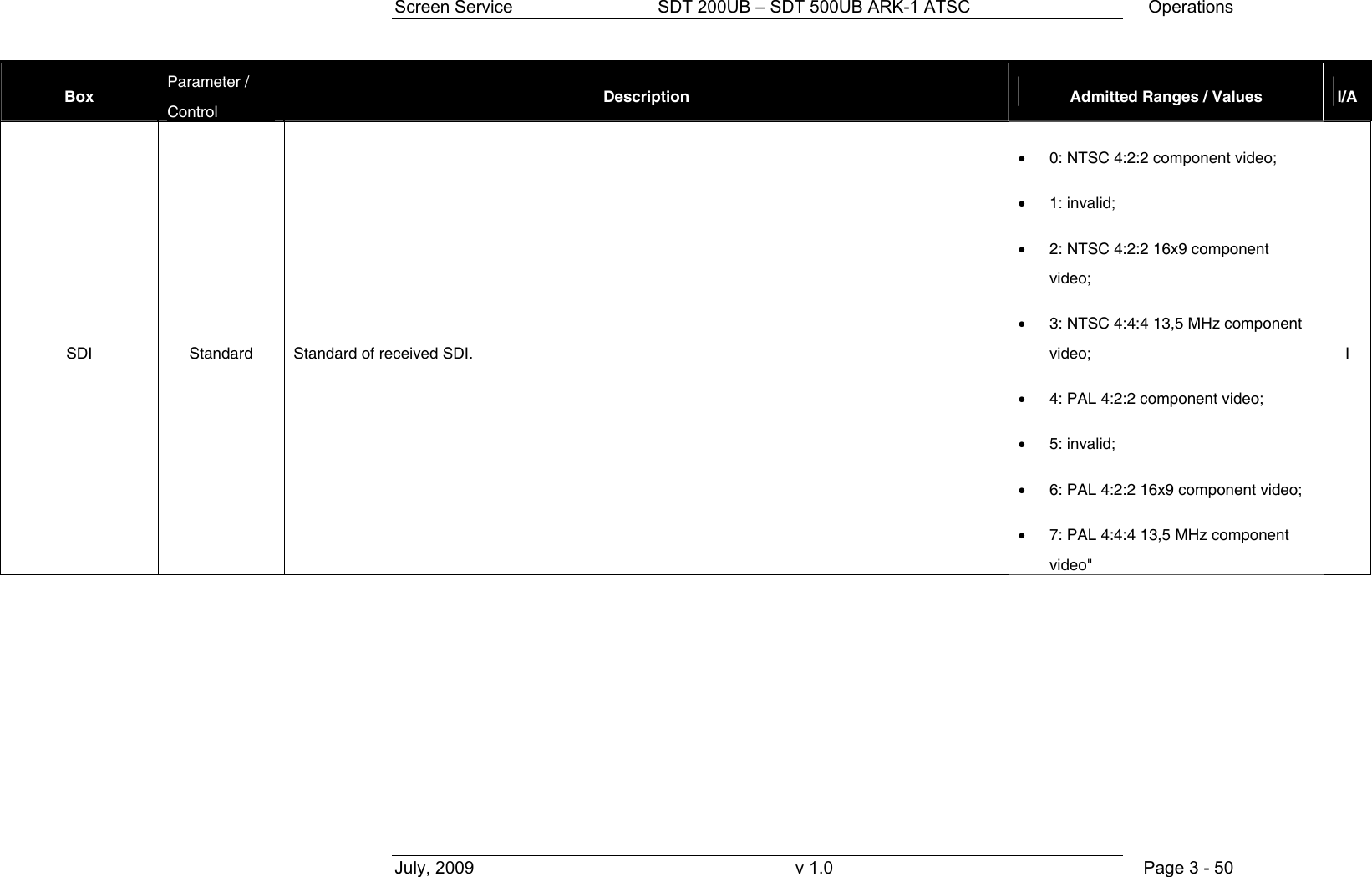
![Screen Service SDT 200UB – SDT 500UB ARK-1 ATSC Operations July, 2009 v 1.0 Page 3 - 24 OID Name R\W Description .6 error 0: off 1: on 1.3.6.1.4.1.21678.186.3.2.2.2.4.7 ark1atsc_GbeRxCh2Protocol R Not implemented - GbE Rx channel 2 transmission protocol 0: udp 1: rtp 1.3.6.1.4.1.21678.186.3.2.3 ark1atsc_StatisticsItu 1.3.6.1.4.1.21678.186.3.2.3.1 ark1atsc_ItuSdi 1.3.6.1.4.1.21678.186.3.2.3.1.1 ark1atsc_Sdi1 1.3.6.1.4.1.21678.186.3.2.3.1.1.1 ark1atsc_Sdi1Lock R Sdi 1 lock status 0: unlock 1: lock 1.3.6.1.4.1.21678.186.3.2.3.1.1.2 ark1atsc_Sdi1Cd R Sdi 1 carrier detect alarm 0: lock 1: unlock 1.3.6.1.4.1.21678.186.3.2.3.1.1.3 ark1atsc_Sdi1Standard R Sdi 1 standard 0: NTSC 4:2:2 component video 1: invalid 2: NTSC 4:2:2 16x9 component video 3: NTSC 4:4:4 13,5 MHz component video 4: PAL 4:2:2 component video 5: invalid 6: PAL 4:2:2 16x9 component video 7: PAL 4:4:4 13,5 MHz component video 1.3.6.1.4.1.21678.186.3.2.3.1.2 ark1atsc_Sdi2 1.3.6.1.4.1.21678.186.3.2.3.1.2.1 ark1atsc_Sdi2Lock R Sdi 2 lock status 0: unlock 1: lock 1.3.6.1.4.1.21678.186.3.2.3.1.2.2 ark1atsc_Sdi2Cd R Sdi 2 carrier detect alarm 0: lock 1: unlock 1.3.6.1.4.1.21678.186.3.2.3.1.2.3 ark1atsc_Sdi2Standard R Sdi 2 standard 0: NTSC 4:2:2 component video 1: invalid 2: NTSC 4:2:2 16x9 component video 3: NTSC 4:4:4 13,5 MHz component video 4: PAL 4:2:2 component video 5: invalid 6: PAL 4:2:2 16x9 component video 7: PAL 4:4:4 13,5 MHz component video 1.3.6.1.4.1.21678.186.4 ark1atsc_Modulation 1.3.6.1.4.1.21678.186.4.1 ark1atsc_Modulation_Settings 1.3.6.1.4.1.21678.186.4.1.1 ark1atsc_Modulation_Atsc 1.3.6.1.4.1.21678.186.4.1.1.1 ark1atsc_Modulation_Atsc_DelNullPck RW Delete null packets enable 0: disabled 1: enable 1.3.6.1.4.1.21678.186.4.1.2 ark1atsc_Modulation_Itu 1.3.6.1.4.1.21678.186.4.1.2.1 ark1atsc_Modulation_Itu_Video 1.3.6.1.4.1.21678.186.4.1.2.1.1 ark1atsc_Modulation_Itu_Video_Whitelevel RW White level [%] (range 10 to 22) = [(x*0.05) + 10] (x: range 0 to 240) 1.3.6.1.4.1.21678.186.4.1.2.1.2 ark1atsc_Modulation_Itu_Video_SynchAmplitude RW Synch Amplitude [%] (range: 22 to 27,5) = [(x*0.05) + 20] (x: range 40 to 150) 1.3.6.1.4.1.21678.186.4.1.2.1.3 ark1atsc_Modulation_Itu_Video_PedesL RW Pedes leve [%] (range: 0 to 7) = (x*0.05) (x:](https://usermanual.wiki/Screen-Service-Broadcasting-Technologies/SDTX-ARK1/User-Guide-1525670-Page-46.png)
![Screen Service SDT 200UB – SDT 500UB ARK-1 ATSC Operations July, 2009 v 1.0 Page 3 - 25 OID Name R\W Description evel range 0 to 140) 1.3.6.1.4.1.21678.186.4.1.2.2 ark1atsc_Modulation_Itu_Audio 1.3.6.1.4.1.21678.186.4.1.2.2.1 ark1atsc_Modulation_Itu_Audio_Deviation RW Audio deviation 1.3.6.1.4.1.21678.186.4.1.2.2.2 ark1atsc_Modulation_Itu_Audio_CarrierLevel1 RW Carrier Level 1 [dB] (range: -7 to -22) = [-1* (x/10)] (range 70 to 220) 1.3.6.1.4.1.21678.186.4.1.2.2.3 ark1atsc_Modulation_Itu_Audio_CarrierLevel2 RW Carrier Level 2 [dB] (range: -7 to -22) = [-1* (x/10)] (range 70 to 220) 1.3.6.1.4.1.21678.186.4.1.2.2.4 ark1atsc_Modulation_Itu_Audio_Emphasis R Monitor emphasis 0: 50 us 1: 75 us 2: no emphasis 3: no emphasis 1.3.6.1.4.1.21678.186.4.1.2.2.5 ark1atsc_Modulation_Itu_Audio_Type RW Select Audio type 0: mono dual carrier 1: dual sound 2: stereo 3: mono single carrier 1.3.6.1.4.1.21678.186.4.2 ark1atsc_Modulation_Test 1.3.6.1.4.1.21678.186.4.2.1 ark1atsc_Test_Common 1.3.6.1.4.1.21678.186.4.2.1.1 ark1atsc_Test_Cw RW Test CW enable 0: disabled 1: enabled 1.3.6.1.4.1.21678.186.4.2.2 ark1atsc_Test_Atsc 1.3.6.1.4.1.21678.186.4.2.2.1 ark1atsc_Test_ForceNullPck RW Force null packets enable 0: disabled 1: enabled 1.3.6.1.4.1.21678.186.4.2.3 ark1atsc_Test_Itu 1.3.6.1.4.1.21678.186.4.2.3.1 ark1atsc_Test_Cw_Av RW Test CW A/V enable 0: disabled 1: enabled 1.3.6.1.4.1.21678.186.4.2.3.2 ark1atsc_Test_Video RW Test video selector 0: bars 1: no video test 1.3.6.1.4.1.21678.186.4.2.3.3 ark1atsc_Test_Audio RW Test audio selector 0: no audio test 1: test tone 1.3.6.1.4.1.21678.186.4.2.3.4 ark1atsc_Test_Tone_Right RW Right tone frequency (range:0 to127) [unit x 100Hz] 1.3.6.1.4.1.21678.186.4.2.3.5 ark1atsc_Test_Tone_Left RW Left tone frequency (range:0 to127) [unit x 100Hz] 1.3.6.1.4.1.21678.186.4.2.3.6 ark1atsc_Test_Mute_Audio_Enable RW Mute audio enable 0: disabled 1: enabled 1.3.6.1.4.1.21678.186.5 ark1atsc_Output 1.3.6.1.4.1.21678.186.5.1 ark1atsc_OutputSettings 1.3.6.1.4.1.21678.186.5.1.1 ark1atsc_OutputSettingsA 1.3.6.1.4.1.21678.186.5.1.1.1 ark1atsc_SettingsAChannel RW Mode A: output channel 1.3.6.1.4.1.21678.186.5.1.1.2 ark1atsc_SettingsAFrequencyOffset RW Mode A: output frequency offset expressed in Hz (from -4,000,000 up to 4,000,000) 1.3.6.1.4.1.21678.186.5.1.1.3 ark1atsc_SettingsAPower RW Mode A: output power 1.3.6.1.4.1.21678.186.5.1.2 ark1atsc_OutputSettingsB 1.3.6.1.4.1.21678.186.5.1.2.1 ark1atsc_SettingsBChannel RW Mode B: output channel 1.3.6.1.4.1.21678.186.5.1.2.2 ark1atsc_SettingsBFrequencyOffset RW Mode B: output frequency offset expressed in Hz (from -4,000,000 up to 4,000,000)](https://usermanual.wiki/Screen-Service-Broadcasting-Technologies/SDTX-ARK1/User-Guide-1525670-Page-47.png)
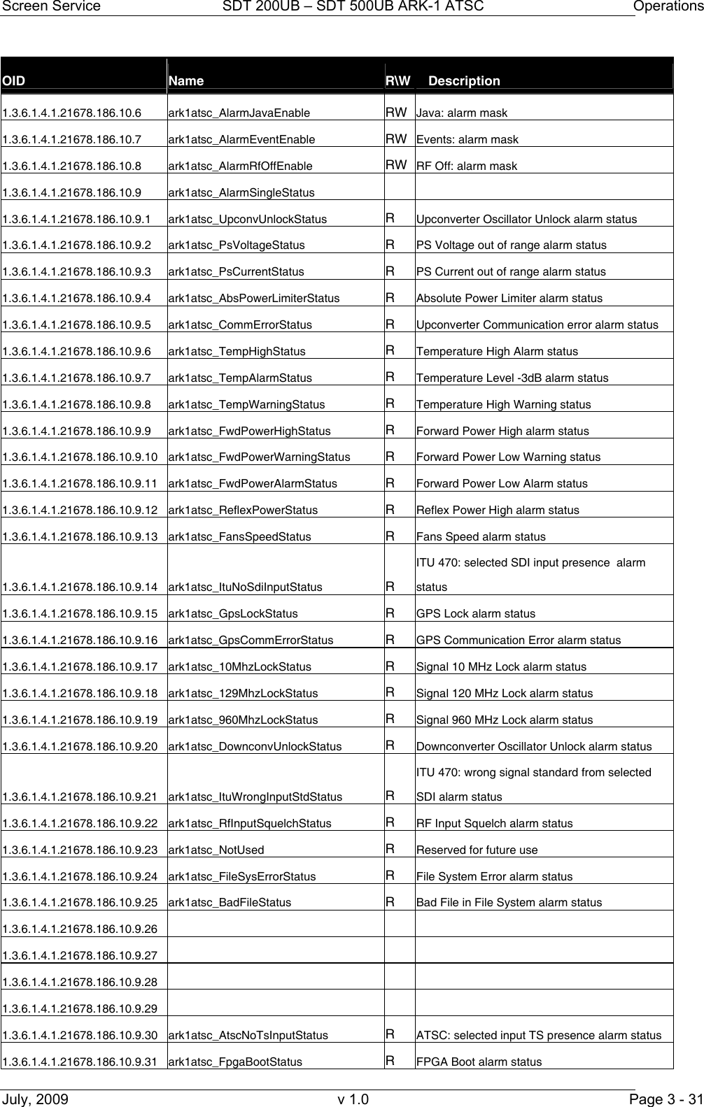
![Screen Service SDT 200UB – SDT 500UB ARK-1 ATSC Operations July, 2009 v 1.0 Page 3 - 27 OID Name R\W Description 1.3.6.1.4.1.21678.186.5.4.2 ark1atsc_NotUsed 1.3.6.1.4.1.21678.186.5.5 ark1atsc_OutputMonitor 1.3.6.1.4.1.21678.186.5.5.1 ark1atsc_Monitor_FwdPowerDbm R Forward power [dBm x 10] indicator 1.3.6.1.4.1.21678.186.5.5.2 ark1atsc_Monitor_AgcMode R AGC mode status 0: analog 1: digital 1.3.6.1.4.1.21678.186.5.5.3 ark1atsc_Monitor_AgcOn R Auto AGC status 0: off 1: on 1.3.6.1.4.1.21678.186.6 ark1atsc_HW_monitor 1.3.6.1.4.1.21678.186.6.1 ark1atsc_HW_monitor_RflPowerDbm R Reflex power [dBm x 10] 1.3.6.1.4.1.21678.186.6.2 ark1atsc_HW_monitor_Amplifier R Amplifier status 0: on 1: off 2: restart 3: stand by off 4: GPS off 5: init 6: alarm off 7: rf off 8: opto off 9: change mode 1.3.6.1.4.1.21678.186.6.3 ark1atsc_HW_monitor_CurrentOut R Current indicator (mA) 1.3.6.1.4.1.21678.186.6.4 ark1atsc_HW_monitor_PowerSupply R Voltage indicator (mV): 28V for 20W and 50W versions, and 42V for 200W version 1.3.6.1.4.1.21678.186.6.5 ark1atsc_HW_monitor_FanPulse 1.3.6.1.4.1.21678.186.6.5.1 ark1atsc_FanSpeed1 R FAN 1 speed (rpm) 1.3.6.1.4.1.21678.186.6.5.2 ark1atsc_FanSpeed2 R FAN 2 speed (rpm) 1.3.6.1.4.1.21678.186.6.5.3 ark1atsc_FanSpeed3 R FAN 3 speed (rpm) - only for 200W version 1.3.6.1.4.1.21678.186.6.5.4 ark1atsc_FanSpeed4 R FAN 4 speed (rpm) - only for 200W version 1.3.6.1.4.1.21678.186.6.6 ark1atsc_HW_monitor_Temperature 1.3.6.1.4.1.21678.186.6.6.1 ark1atsc_TemperatureCase R Case temperature 1.3.6.1.4.1.21678.186.6.6.2 ark1atsc_TemperaturePsu R PSU temperature 1.3.6.1.4.1.21678.186.6.6.3 ark1atsc_TemperatureCase2 R Case temperature 2 (only in SDTX 200 version) 1.3.6.1.4.1.21678.186.6.7 ark1atsc_HW_monitor_Relays 1.3.6.1.4.1.21678.186.6.7.1 ark1atsc_Relay0Status R Relay 0 status 0: on 1: off 1.3.6.1.4.1.21678.186.6.7.2 ark1atsc_Relay1Status R Relay 1 status 0: on 1: off 1.3.6.1.4.1.21678.186.6.7.3 ark1atsc_Relay2Status R Relay 2 status 0: on 1: off 1.3.6.1.4.1.21678.186.6.7.4 ark1atsc_Relay3Status R Relay 3 status 0: on 1: off 1.3.6.1.4.1.21678.186.6.8 ark1atsc_HW_monitor_Opto 1.3.6.1.4.1.21678.186.6.8.1 ark1atsc_Opto0Status R Opto 0 status (RF Off): if closed the output RF is switch off 0: closed 1: opened 1.3.6.1.4.1.21678.186.6.8.2 ark1atsc_Opto1Status R Opto 1 status (Mode Switch): if closed Mode B, otherwise Mode A 0: closed 1: opened 1.3.6.1.4.1.21678.186.6.8.3 ark1atsc_Opto2Status R Opto 2 status (Retry, only in 200 watt version) 0: closed 1: opened 1.3.6.1.4.1.21678.186.6.8.4 ark1atsc_Opto3Status R Opto 3 status (Stand-by): if closed the device is put on stand-by 0: closed 1: opened 1.3.6.1.4.1.21678.186.6.9 ark1atsc_HW_monitor_PowerSupply24V R 24V voltage indicator (mV), only in 200 watt version](https://usermanual.wiki/Screen-Service-Broadcasting-Technologies/SDTX-ARK1/User-Guide-1525670-Page-49.png)
![Screen Service SDT 200UB – SDT 500UB ARK-1 ATSC Operations July, 2009 v 1.0 Page 3 - 28 OID Name R\W Description 1.3.6.1.4.1.21678.186.7 ark1atsc_Gps 1.3.6.1.4.1.21678.186.7.1 ark1atsc_GpsSat 1.3.6.1.4.1.21678.186.7.1.1 ark1atsc_SatVisible R Number of visible satellite 1.3.6.1.4.1.21678.186.7.1.2 ark1atsc_SatTracked R Number of satellite locked 1.3.6.1.4.1.21678.186.7.2 ark1atsc_GpsStatus 1.3.6.1.4.1.21678.186.7.2.1 ark1atsc_StatusDataValid R Signal precision status 0: Not valid 1: Valid 1.3.6.1.4.1.21678.186.7.3 ark1atsc_GpsPosition 1.3.6.1.4.1.21678.186.7.3.1 ark1atsc_PositionLatitude R Latitude position [°] 1.3.6.1.4.1.21678.186.7.3.2 ark1atsc_PositionLongitude R Longitude position [°] 1.3.6.1.4.1.21678.186.7.4 ark1atsc_GpsTime 1.3.6.1.4.1.21678.186.7.4.1 ark1atsc_TimeActual R UTC time 1.3.6.1.4.1.21678.186.7.4.2 ark1atsc_TimeDate R UTC date 1.3.6.1.4.1.21678.186.8 ark1atsc_Clock 1.3.6.1.4.1.21678.186.8.1 ark1atsc_ClockSel10MhzReference RW 10 MHz frequency reference 0: ext 1: int 2: gps 1.3.6.1.4.1.21678.186.8.2 ark1atsc_ClockSel1Pps RW 1PPS frequency reference 0: int 1: ext 1.3.6.1.4.1.21678.186.8.3 ark1atsc_GainFineTuning RW Gain fine tuning (from 0 up to 255) 1.3.6.1.4.1.21678.186.9 ark1atsc_Network 1.3.6.1.4.1.21678.186.9.1 ark1atsc_NetworkManagement 1.3.6.1.4.1.21678.186.9.1.1 ark1atsc_ManagementMacAddress R Board MAC address 1.3.6.1.4.1.21678.186.9.1.2 ark1atsc_ManagementIpAddress R Board IP address 1.3.6.1.4.1.21678.186.9.1.3 ark1atsc_ManagementNetmask R Subnet mask 1.3.6.1.4.1.21678.186.9.1.4 ark1atsc_ManagementGateway R Gateway address 1.3.6.1.4.1.21678.186.9.1.5 ark1atsc_ManagementUdpPort RW UDP port 1.3.6.1.4.1.21678.186.9.1.6 ark1atsc_ManagementSpeed R GBE Speed 0: 10 Mbit 1: 100 Mbit 2: 1 Gbit 1.3.6.1.4.1.21678.186.9.1.7 ark1atsc_ManagementGoodFrame R GbE good frame counter 1.3.6.1.4.1.21678.186.9.1.8 ark1atsc_ManagementBadFrame R GbE bad frame counter 1.3.6.1.4.1.21678.186.9.2 ark1atsc_NetworkIgmp 1.3.6.1.4.1.21678.186.9.2.1 ark1atsc_IgmpEnable RW Not implemented - IGMP enable 0: disabled 1: enabled 1.3.6.1.4.1.21678.186.9.3 ark1atsc_NetworkTxChannel1 1.3.6.1.4.1.21678.186.9.3.1 ark1atsc_TxChannel1Type RW Not implemented - Tx channel 1: transmission protocol selector 0: RTP 1: UDP 1.3.6.1.4.1.21678.186.9.3.2 ark1atsc_TxChannel1TsFormat RW Not implemented - Tx channel 1: packet format 0: 204 1: 188 1.3.6.1.4.1.21678.186.9.3.3 ark1atsc_TxChannel1TsNum RW Not implemented - Tx channel 1: number of TS packet per frame 1.3.6.1.4.1.21678.186.9.3.4 ark1atsc_TxChannel1IpAddr RW Not implemented - Tx channel 1: destination IP](https://usermanual.wiki/Screen-Service-Broadcasting-Technologies/SDTX-ARK1/User-Guide-1525670-Page-50.png)
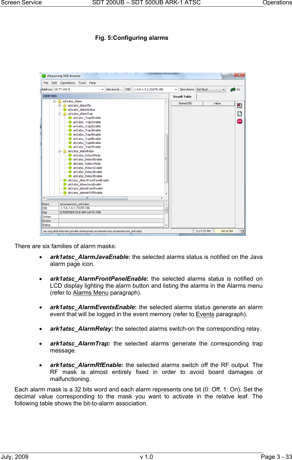
![Screen Service SDT 200UB – SDT 500UB ARK-1 ATSC Operations July, 2009 v 1.0 Page 3 - 30 OID Name R\W Description 1.3.6.1.4.1.21678.186.9.7.6 ark1atsc_Trap5IpAddress RW Trap 5: destination IP address 1.3.6.1.4.1.21678.186.9.7.7 ark1atsc_Trap6IpAddress RW Trap 6: destination IP address 1.3.6.1.4.1.21678.186.9.7.8 ark1atsc_Trap7IpAddress RW Trap 7: destination IP address 1.3.6.1.4.1.21678.186.10 ark1atsc_Alarm 1.3.6.1.4.1.21678.186.10.1 ark1atsc_AlarmThr 1.3.6.1.4.1.21678.186.10.1.1 ark1atsc_Not_implemented 1.3.6.1.4.1.21678.186.10.1.2 ark1atsc_ThrRfSquelchA RW Mode A: Squelch threshold (absolute value) 1.3.6.1.4.1.21678.186.10.1.3 ark1atsc_ThrRfSquelchB RW Mode B: Squelch threshold (absolute value) 1.3.6.1.4.1.21678.186.10.1.4 ark1atsc_ThrFwdPowerWarning RW Forward power warning threshold (absolute value [dBm x 10] ) 1.3.6.1.4.1.21678.186.10.1.5 ark1atsc_ThrFwdPowerAlarm RW Forward power alarm threshold (absolute value [dBm x 10]) 1.3.6.1.4.1.21678.186.10.1.6 ark1atsc_ThrTemperatureWarning RW Case temperature warning threshold 1.3.6.1.4.1.21678.186.10.1.7 ark1atsc_ThrTemperatureAlarm RW Case temperature alarm threshold 1.3.6.1.4.1.21678.186.10.1.8 ark1atsc_Not_implemented 1.3.6.1.4.1.21678.186.10.1.9 ark1atsc_Not_implemented 1.3.6.1.4.1.21678.186.10.1.10 ark1atsc_InputAlarmDelay RW TS input missing alarm delay [val * 100 ms] 1.3.6.1.4.1.21678.186.10.2 ark1atsc_AlarmStatus R 32 bits word indicating alarms status (each bit is associated to an alarm) 1.3.6.1.4.1.21678.186.10.3 ark1atsc_AlarmTrap 1.3.6.1.4.1.21678.186.10.3.1 ark1atsc_Trap0Enable RW Trap 0: alarm mask 1.3.6.1.4.1.21678.186.10.3.2 ark1atsc_Trap1Enable RW Trap 1: alarm mask 1.3.6.1.4.1.21678.186.10.3.3 ark1atsc_Trap2Enable RW Trap 2: alarm mask 1.3.6.1.4.1.21678.186.10.3.4 ark1atsc_Trap3Enable RW Trap 3: alarm mask 1.3.6.1.4.1.21678.186.10.3.5 ark1atsc_Trap4Enable RW Trap 4: alarm mask 1.3.6.1.4.1.21678.186.10.3.6 ark1atsc_Trap5Enable RW Trap 5: alarm mask 1.3.6.1.4.1.21678.186.10.3.7 ark1atsc_Trap6Enable RW Trap 6: alarm mask 1.3.6.1.4.1.21678.186.10.3.8 ark1atsc_Trap7Enable RW Trap 7: alarm mask 1.3.6.1.4.1.21678.186.10.4 ark1atsc_AlarmRelay 1.3.6.1.4.1.21678.186.10.4.1 ark1atsc_Relay0Mode RW Relay 0: mode selector 0: alarm mask 1: mode indicator 2: RF status 1.3.6.1.4.1.21678.186.10.4.2 ark1atsc_Relay0Enable RW Relay 0: alarm mask 1.3.6.1.4.1.21678.186.10.4.3 ark1atsc_Relay1Mode RW Relay 1: mode selector 0: alarm mask 1: mode indicator 1.3.6.1.4.1.21678.186.10.4.4 ark1atsc_Relay1Enable RW Relay 1: alarm mask 1.3.6.1.4.1.21678.186.10.4.6 ark1atsc_Relay2Enable RW Relay 2: alarm mask 1.3.6.1.4.1.21678.186.10.4.8 ark1atsc_Relay3Enable RW Relay 3: alarm mask 1.3.6.1.4.1.21678.186.10.5 ark1atsc_AlarmFrontPanelEnable RW Front panel: alarm mask](https://usermanual.wiki/Screen-Service-Broadcasting-Technologies/SDTX-ARK1/User-Guide-1525670-Page-52.png)
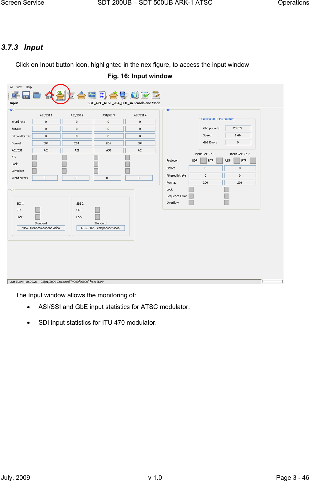
![Screen Service SDT 200UB – SDT 500UB ARK-1 ATSC Operations July, 2009 v 1.0 Page 3 - 47 Table 8. Input window Box Parameter / Control Description Admitted Ranges / Values I/A ASI/SSI Word rate ASI input word rate. 10 bits word rate of ASI input (Ref. to CEI EN 50083-9). Approximately 27 Mword/s A ASI/SSI Bitrate [bit/s] ASI input bitrate. A ASI/SSI Filtered bitrate [bit/s] Bit-rate actually used by the modulator. • Zero when the input has not been selected • Equal to the total bitrate, when Delete Null Packets disabled • Less than total bitrate, when Delete Null Packets enabled A ASI/SSI Format Format of received TS Packets (Ref. to CEI EN 50083-9). • 188 Bytes • 204 Bytes A ASI/SSI CD ASI Carrier detection flag. • Green: Detected • Grey: Not detected A ASI/SSI Lock ASI lock status. The input Transport Stream is unlocked when more than two consecutive Sync Byte are missed then five consecutive Sync Bytes must occur to regain the lock (Ref. to ETSI ETR-291) • Green: Locked • Grey: Not locked A ASI/SSI Overflow ASI input overflow indicator. This alarm condition occurs when the input bit-rate exceeds the capability of the modulation (Ref. to ATSC A/53). • Red: Alarm • Grey: No alarms A](https://usermanual.wiki/Screen-Service-Broadcasting-Technologies/SDTX-ARK1/User-Guide-1525670-Page-69.png)
![Screen Service SDT 200UB – SDT 500UB ARK-1 ATSC Operations July, 2009 v 1.0 Page 3 - 48 Box Parameter / Control Description Admitted Ranges / Values I/A ASI/SSI Word Errors Total amount of ASI wrong words received. A RTP Protocol Not implemented - Ethernet input packets protocol. • UDP • RTP A RTP Bitrate [bit/s] Not implemented - Bitrate of TS from Ethernet input. A RTP Filtered bitrate [bit/s] Not implemented - Bitrate actually used by the modulator. • Zero when the input is not selected • Equal to the total bitrate, when Delete Null Packets disabled • Less than total bitrate, when Delete Null Packets enabled A RTP Format Not implemented - Format of received TS Packets (Ref. to CEI EN 50083-9). • 188 Bytes • 204 Bytes A RTP Lock Not implemented - TS lock status. The input Transport Stream is unlocked when more than two consecutive Sync Byte are missed then five consecutive Sync Bytes must occur to regain the lock (Ref. to ETSI ETR-291) • Green: Locked • Grey: Not locked A RTP Sequence error Not implemented - Ethernet input Sequence error alarm status. This alarm condition occurs when an error in the sequence of input packets at IP level occurs. • Red: Alarm • Grey: No alarms A RTP Overflow Not implemented - Input GbE overflow alarm status. This alarm condition occurs when the input bitrate exceeds the capability of the modulation (Ref. to ATSC A/53). • Red: Alarm on • Grey: Alarm off A](https://usermanual.wiki/Screen-Service-Broadcasting-Technologies/SDTX-ARK1/User-Guide-1525670-Page-70.png)
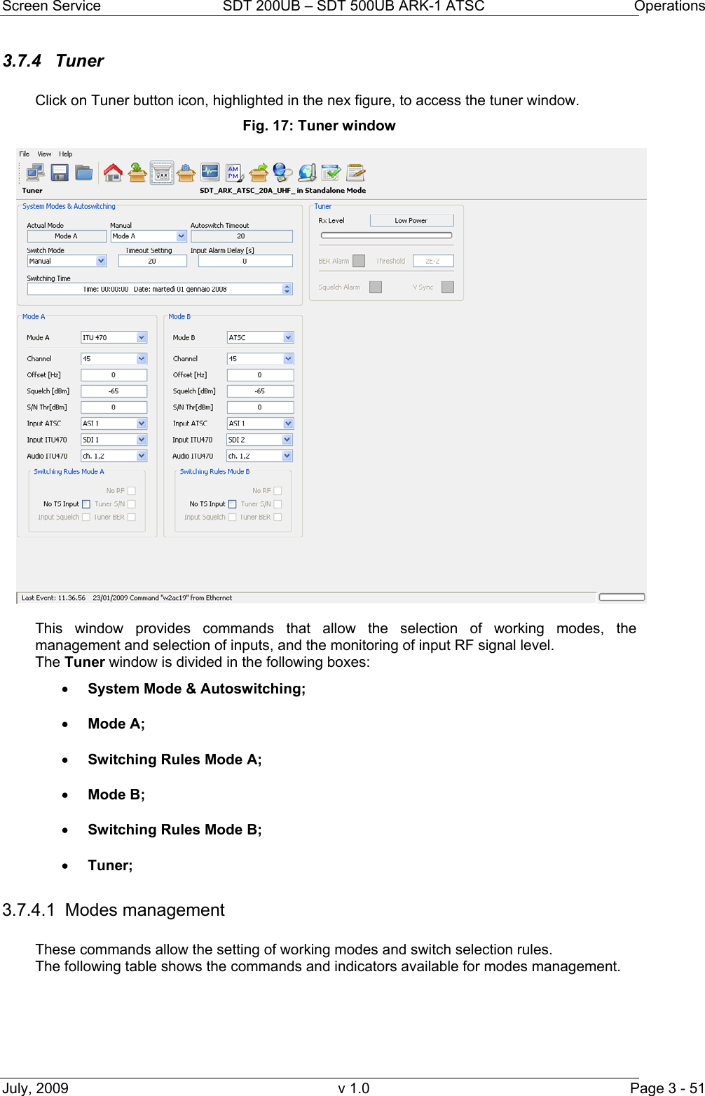
![Screen Service SDT 200UB – SDT 500UB ARK-1 ATSC Operations July, 2009 v 1.0 Page 3 - 52 Table 9. Tuner window: modes management Box Parameter / Control Description Admitted Ranges / Values I/A System Mode & Autoswitching Actual mode Current operating mode. • Mode A • Mode B I/A System Mode & Autoswitching Manual Mode selector used when Manual Switch mode is selected. • Mode A • Mode B I/A System Mode & Autoswitching Switch mode Selector of the switch mode rules. Refer to Switching modes rules paragraph for a detailed description of the switching rules and conditions. • Manual • Auto • Opto • Time A System Mode & Autoswitching Autoswitch Timeout When Auto Switch Mode is enabled shows the time to wait for switching. If the used input regains lock before the countdown reaches 0 the switch is blocked and device keeps the same mode. • Countdown from 255 to 0 s A System Mode & Autoswitching Timeout setting Setting of the time to wait for switching. Note: It is highly recommended to set a timeout value different from zero as to allow the input signal locking. • Min: 0 s • Max: 255 s A System Mode & Autoswitching Input Alarm Delay [s] Not implemented - Time to wait for No Input alarm rising expressed in seconds (refer to Alarms paragraph). Note: It is highly recommended to set an Input Alarm Delay value different from zero as to allow the input signal locking. • Min: 1 s • Max: 25.5 s A](https://usermanual.wiki/Screen-Service-Broadcasting-Technologies/SDTX-ARK1/User-Guide-1525670-Page-74.png)
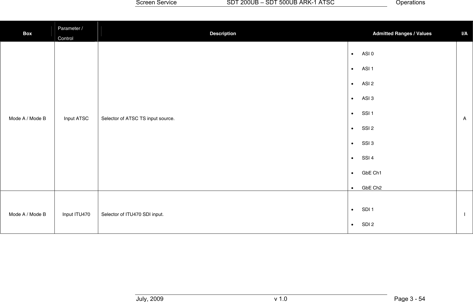
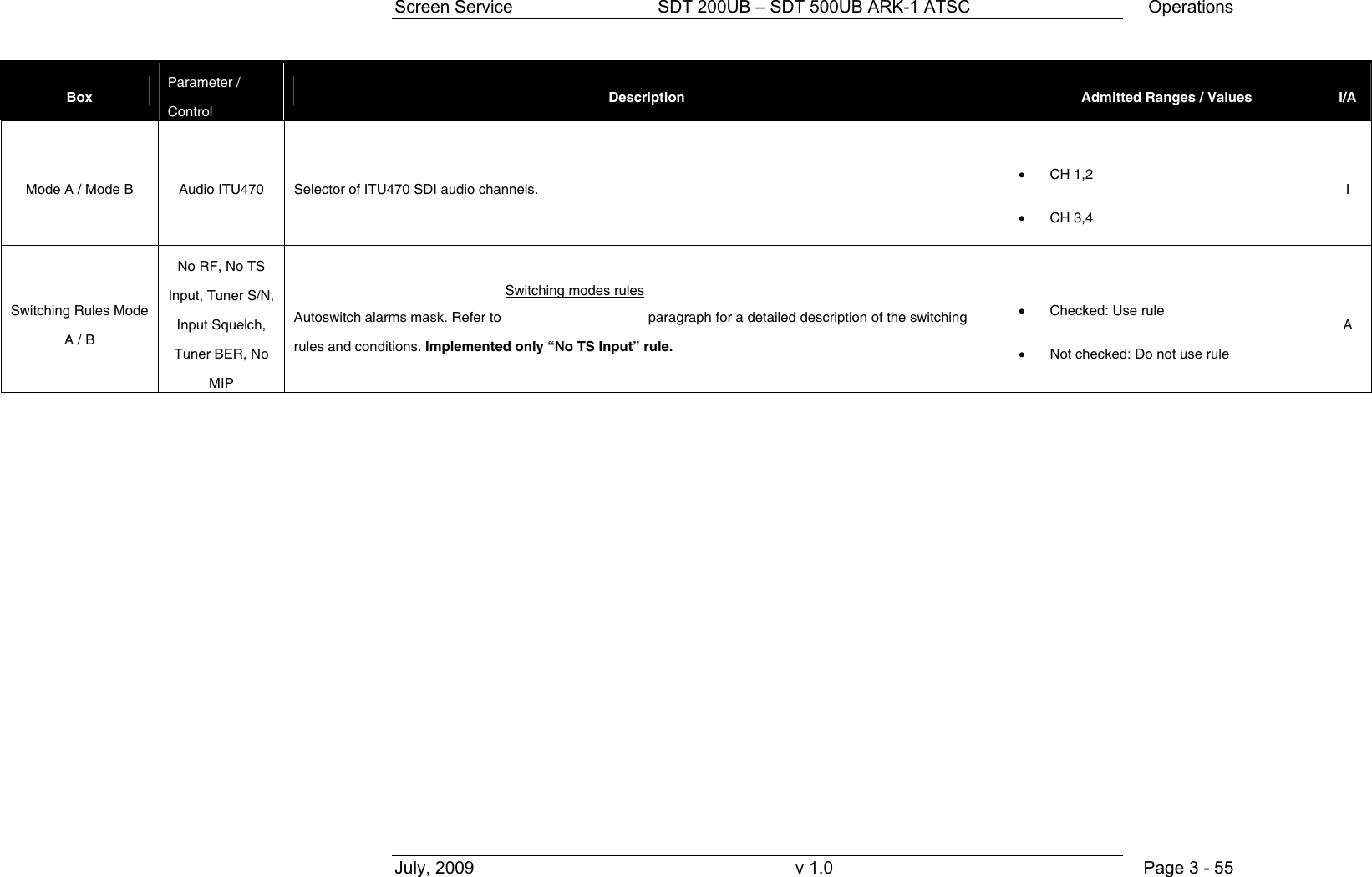
![Screen Service SDT 200UB – SDT 500UB ARK-1 ATSC Operations July, 2009 v 1.0 Page 3 - 53 Box Parameter / Control Description Admitted Ranges / Values I/A System Mode & Autoswitching Switching Time Time and date setting for modes switching when Time Switch mode is enabled. I/A Mode A / Mode B Mode A / B Selector of working mode. Two different working modes are provided: • ITU 470 modulator • ATSC modulator • ITU 470 • ATSC I/A Mode A / Mode B Channel Selector of the UHF input channel used as RF input. • Min: 14 • Max: 77 A Mode A / Mode B Offset [Hz] Frequency offset from the channel center frequency of the RF input. 1 Hz step variation. • Min: -4 MHz • Max: 4 MHz A Mode A / Mode B Squelch [dBm] Squelch alarm threshold expressed in dBm. Input is squelched when the RF level is under this threshold. • Min: -70 • Max: -20 A Mode A / Mode B S/N Thr [dBm] Not implemented - Signal / Noise alarm threshold • Min: -10 dBm • Max: –50 dBm A](https://usermanual.wiki/Screen-Service-Broadcasting-Technologies/SDTX-ARK1/User-Guide-1525670-Page-75.png)
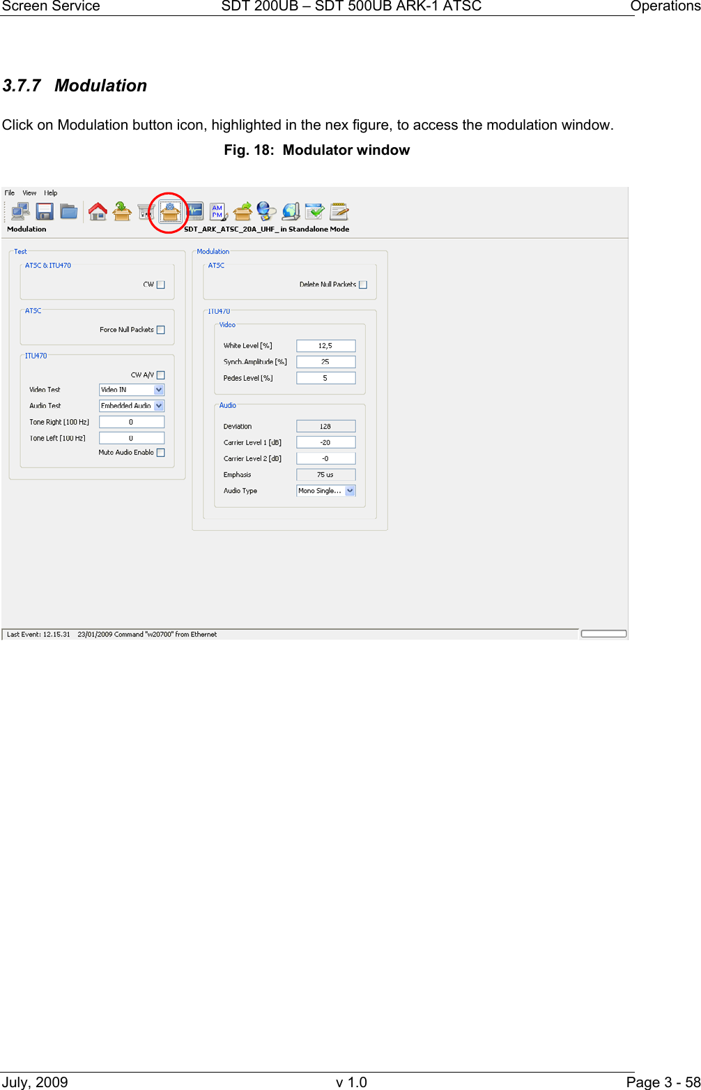
![Screen Service SDT 200UB – SDT 500UB ARK-1 ATSC Operations July, 2009 v 1.0 Page 3 - 60 Box Parameter / Control Description Admitted Ranges / Values I/A Test: ITU 470 Tone Right [100 KHz] Right tone frequency setting. Not used for NTSC • MIN: 0 • MAX: 127 I Test: ITU 470 Tone Left [100 KHz] Left tone frequency setting. • MIN: 0 • MAX: 127 I Test: ITU 470 Mute Audio Enable Audio mute enable • Not checked: audio mute disabled • Checked: audio mute enabled I Modulation ATSC Delete null packets Delete null packets function enable. • Not checked: Delete null packets disabled • Checked: Delete null packets enabled A](https://usermanual.wiki/Screen-Service-Broadcasting-Technologies/SDTX-ARK1/User-Guide-1525670-Page-82.png)
![Screen Service SDT 200UB – SDT 500UB ARK-1 ATSC Operations July, 2009 v 1.0 Page 3 - 61 Box Parameter / Control Description Admitted Ranges / Values I/A Modulation ITU470 video White level [%] Video white level setting. The level value is in percentage upon the synch level. The synch level is taken as 100% reference. • MIN: 10 • MAX: 22 • Step: 0,05 I Modulation ITU470 video Synch Amplitude [%] Video synch amplitude setting. The level value is in percentage upon the synch level. The synch level is taken as 100% reference. • MIN: 22 • MAX: 27,5 • Step: 0,05 I Modulation ITU470 video Pedes level [%] Video pedes level setting. The level value is in percentage upon the synch level. The synch level is taken as 100% reference. • MIN: 0 • MAX: 7 • Step: 0,05 I Modulation ITU470 audio Deviation Audio deviation monitor. • I](https://usermanual.wiki/Screen-Service-Broadcasting-Technologies/SDTX-ARK1/User-Guide-1525670-Page-83.png)
![Screen Service SDT 200UB – SDT 500UB ARK-1 ATSC Operations July, 2009 v 1.0 Page 3 - 62 Box Parameter / Control Description Admitted Ranges / Values I/A Modulation ITU470 audio Carrier Level 1 [dB] Audio 2 carrier level setting. • MIN: -7 • MAX: -22 • Step: 0,1 I Modulation ITU470 audio Carrier Level 2 [dB] Audio 1 carrier level setting. Not used for NTSC • MIN: -7 • MAX: -22 • Step: 0,1 I Modulation ITU470 audio Emphasis Audio emphasis value monitor. • 50 us • 75 us • no emphasis I](https://usermanual.wiki/Screen-Service-Broadcasting-Technologies/SDTX-ARK1/User-Guide-1525670-Page-84.png)
![Screen Service SDT 200UB – SDT 500UB ARK-1 ATSC Operations July, 2009 v 1.0 Page 3 - 74 Box Parameter / Control Description Admitted Ranges / Values I/A AGC AGC ON AGC status. • Green: ON • Grey: OFF I/A AGC Mode Current AGC mode indicator. • Analog/Digital: • Green: ON • Grey: OFF I/A Frequency Out [Hz] Frequency Out [Hz] Output center frequency expressed in Hz. I/A](https://usermanual.wiki/Screen-Service-Broadcasting-Technologies/SDTX-ARK1/User-Guide-1525670-Page-96.png)
![Screen Service SDT 200UB – SDT 500UB ARK-1 ATSC Operations July, 2009 v 1.0 Page 3 - 76 Box Parameter / Control Description Admitted Ranges / Values I/A Status 28V / 42V PSU voltage indicator (values are expressed in V). It depends on the hardware type of the device: • 28V for SDTx_ARK1 20W and 50W; • 42V for SDTx_ARK1 200W. I/A Status Current PSU 28V / 42V [A] PSU current indicator (values are expressed in A). I/A Status 24V PSU 24V indicator (values are expressed in V). Only in SDTX 200 version. I/A Status Case Temperature Case temperature indicator (values are expressed in °C). I/A Status Case Temperature 2 2nd Case temperature indicator (values are expressed in °C). Only in SDTX 200 version. I/A Status PSU Temperature PSU temperature indicator (values are expressed in °C). I/A Status Fan 1 Fan 1 speed indicator (values are expressed in rpm). I/A Status Fan 2 Fan 2 speed indicator (values are expressed in rpm). I/A Status Fan 3 Fan 3 speed indicator (values are expressed in rpm). Only in SDTX 200 version. I/A Status Fan 4 Fan 4 speed indicator (values are expressed in rpm). Only in SDTX 200 version. I/A Status FWD Power [dBm] Output forward power indicator (values are expressed in dBm). I/A](https://usermanual.wiki/Screen-Service-Broadcasting-Technologies/SDTX-ARK1/User-Guide-1525670-Page-98.png)
![Screen Service SDT 200UB – SDT 500UB ARK-1 ATSC Operations July, 2009 v 1.0 Page 3 - 77 Box Parameter / Control Description Admitted Ranges / Values I/A Status Reflex Power [dBm] Output reflex power indicator (values are expressed in dBm). I/A Opto & Relay Relay 0 Selector of Relay 0 using mode. • Alarm: indicator of an alarm condition • Mode: indicator of operating mode • RF Status: indicator output RF signal status (on/off) I/A Opto & Relay Relay 1 Selector of Relay 1 using mode. • Alarm: indicator of an alarm condition • Mode: indicator of operating mode I/A Opto & Relay Relay 0…3 Relays status indicators. • Green: Alarm on/Mode A/RF Off • Grey: Alarm off/Mode B/RF On I/A](https://usermanual.wiki/Screen-Service-Broadcasting-Technologies/SDTX-ARK1/User-Guide-1525670-Page-99.png)
![Screen Service SDT 200UB – SDT 500UB ARK-1 ATSC Operations July, 2009 v 1.0 Page 3 - 78 Box Parameter / Control Description Admitted Ranges / Values I/A Opto&Relay Opto 0…3 Opto status indicators. Optos are normally opened: • Opto 0: RF Off, manual switching off of output RF; • Opto 1: Mode A/B switch; • Opto 2: Retry of amplifier alarms (only in SDTX 200 version); • Opto 3: Stand-by enabling; it puts the device on stand-by. • Green: Closed (0) • Grey: Opened (1) I/A Mode A / Mode B Channel Output channel. • Min: 14 • Max: 77 I/A Mode A / Mode B Power [dBm] Output power (expressed in dBm). • SDTx 20/50 o Analog min: 23 dBm I/A](https://usermanual.wiki/Screen-Service-Broadcasting-Technologies/SDTX-ARK1/User-Guide-1525670-Page-100.png)
![Screen Service SDT 200UB – SDT 500UB ARK-1 ATSC Operations July, 2009 v 1.0 Page 3 - 79 Box Parameter / Control Description Admitted Ranges / Values I/A Mode A / Mode B Power [W] Output power (expressed in W). I/A Mode A / Mode B Offset [Hz] Output frequency offset (expressed in Hz). • Min: -4 MHz • Max: 4 MHz I/A FWD Power Thresholds Warning [dB] Forward power warning threshold expressed in dBm. • Min: -16 dBm I/A](https://usermanual.wiki/Screen-Service-Broadcasting-Technologies/SDTX-ARK1/User-Guide-1525670-Page-101.png)
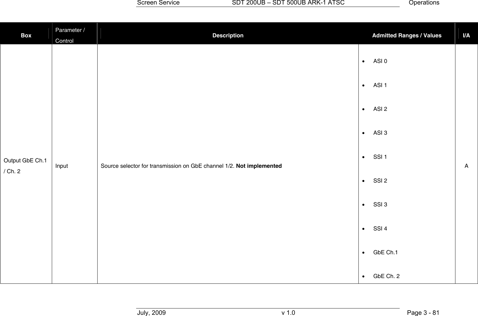
![Screen Service SDT 200UB – SDT 500UB ARK-1 ATSC Operations July, 2009 v 1.0 Page 3 - 80 Box Parameter / Control Description Admitted Ranges / Values I/A FWD Power Thresholds Alarm [dB] Forward power alarm threshold expressed in dBm. I/A Temperature Thresholds Warning Case temperature warning threshold expressed in °C. I/A Temperature Thresholds Alarm Case temperature alarm threshold expressed in °C. • Min: 0 °C • Max: 100 °C I/A Output GbE Ch.1 / Ch. 2 Enable send frame Enable for transmission on GbE channel 1/2. Not implemented • Checked: Enabled • Not checked: Disabled A](https://usermanual.wiki/Screen-Service-Broadcasting-Technologies/SDTX-ARK1/User-Guide-1525670-Page-102.png)
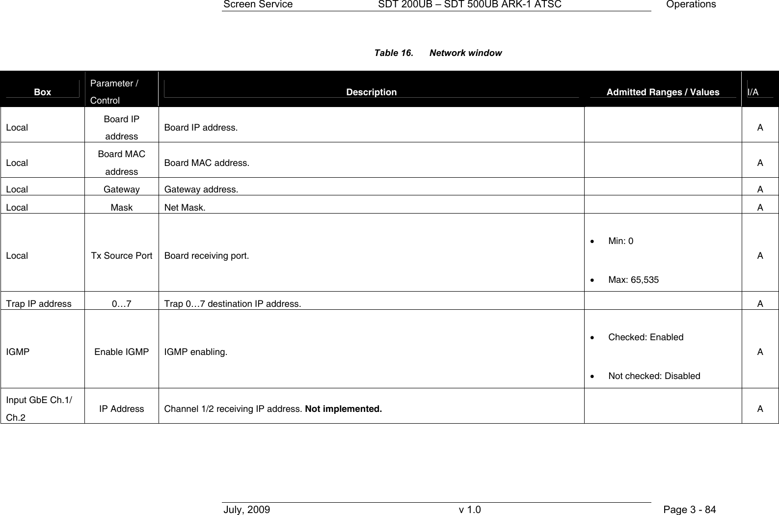
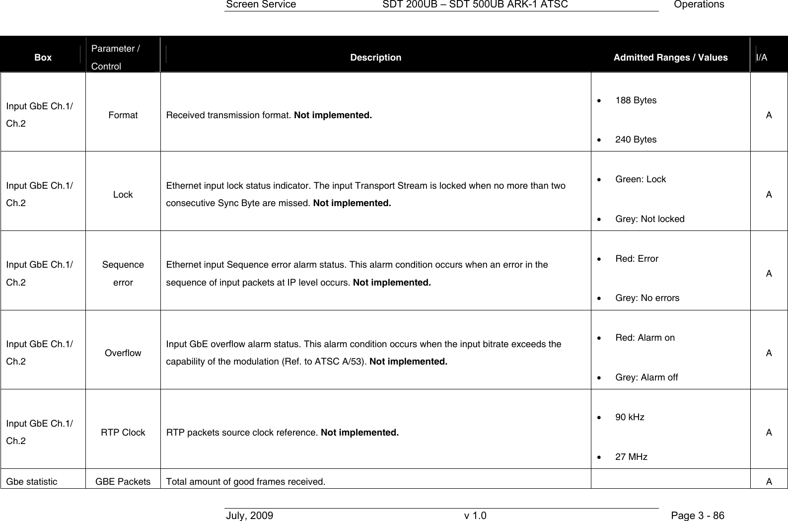
![Screen Service SDT 200UB – SDT 500UB ARK-1 ATSC Operations July, 2009 v 1.0 Page 3 - 85 Box Parameter / Control Description Admitted Ranges / Values I/A Input GbE Ch.1/ Ch.2 Port Channel 1/2 receiving port. Not implemented. • Min: 0 • Max: 65,535 A Input GbE Ch.1/ Ch.2 Protocol Ethernet input packets protocol. Not implemented. • UDP/RTP: o Green: Detected o Grey: Not detected A Input GbE Ch.1/ Ch.2 Bitrate [bit/s] Bitrate of TS from Ethernet input. Not implemented. A Input GbE Ch.1/ Ch.2 Filtered bitrate [bit/s] Bitrate actually used by the modulator. Not implemented. • Zero when the input is not selected • Equal to the total bitrate, when Delete Null Packets disabled • Less than total bitrate, when Delete Null Packets enabled A](https://usermanual.wiki/Screen-Service-Broadcasting-Technologies/SDTX-ARK1/User-Guide-1525670-Page-107.png)

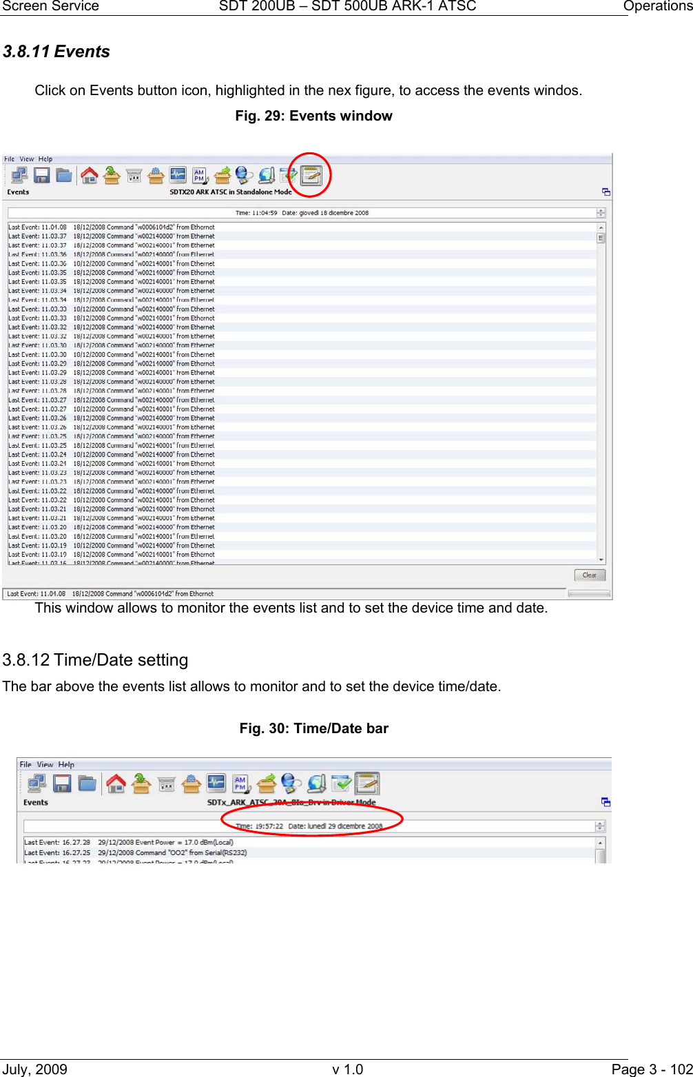
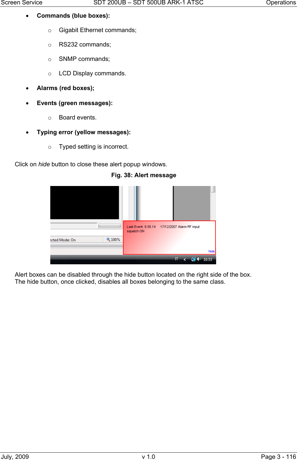
![Screen Service SDT 200UB – SDT 500UB ARK-1 ATSC Operations July, 2009 v 1.0 Page 3 - 115 3.8.18.1.1 Option sub-menu The Option sub-menu allows two controls type: • Time: Time Read Interval [s]; • Alerts: the selection of events to display. Click on the Save button to save Java options; a *.properties file will be created. The device is not loaded with a factory default *.properties file, but it is created and then stored in System File once the properties have been saved. 3.8.18.2 Time Fig. 36: Time window This control allows changing the device-to-management PC java update time. The default value is 2 seconds. Click on Close button to quit this sub-window. 3.8.18.3 Alerts Fig. 37: Alerts window The Alert sub-window allows selecting which types of events will be notified through an Alert box. Alert boxes appear on the right side of the monitor. The selection is performed among the following types of event:](https://usermanual.wiki/Screen-Service-Broadcasting-Technologies/SDTX-ARK1/User-Guide-1525670-Page-137.png)