Screen Service Broadcasting Technologies STDX-ARK-ECHO 20 Watt Multimode SDR Repeater w/ Echo Cancellation User Manual ATSC v1 0
Screen Service Broadcasting Technologies SpA 20 Watt Multimode SDR Repeater w/ Echo Cancellation ATSC v1 0
User Manual ATSC v1.0
![Screen Service SDT ARK 1 ECHO Operations Jan, 2012 v 1.ATSC_FCC Page 3 - 11 3.1.8 BOOT AND WELCOME MESSAGE Turning on the equipment, the display shows the progress bar as follow: When the boot is over, the board is ready. Press ESC to enter the main menu, otherwise after one minute waiting the idle status message appears.Screen ServiceARK - ATSC/DIG-IFSystem InitInit : [ ] WaitScreen ServiceARK - ATSC/DIG-IFBoot FPGAInit : [ ] WaitScreen ServiceARK - ATSC/DIG-IFUp Converter checkInit : [ ] WaitScreen ServiceARK - ATSC/DIG-IFStart systemInit : [ ] WaitScreen ServiceARK - ATSC/DIG-IFStart systemInit : [ ] ReadyScreen ServiceARK - ATSC/DIG-IF10.77.98.44 Ready](https://usermanual.wiki/Screen-Service-Broadcasting-Technologies/STDX-ARK-ECHO/User-Guide-1622747-Page-38.png)
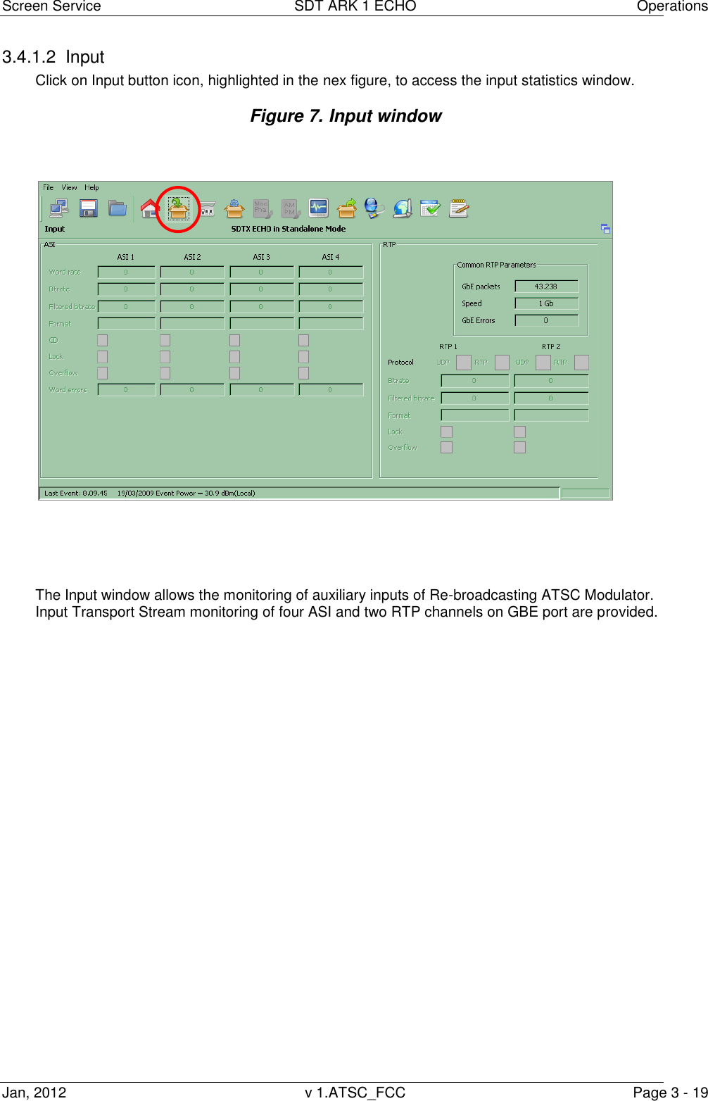
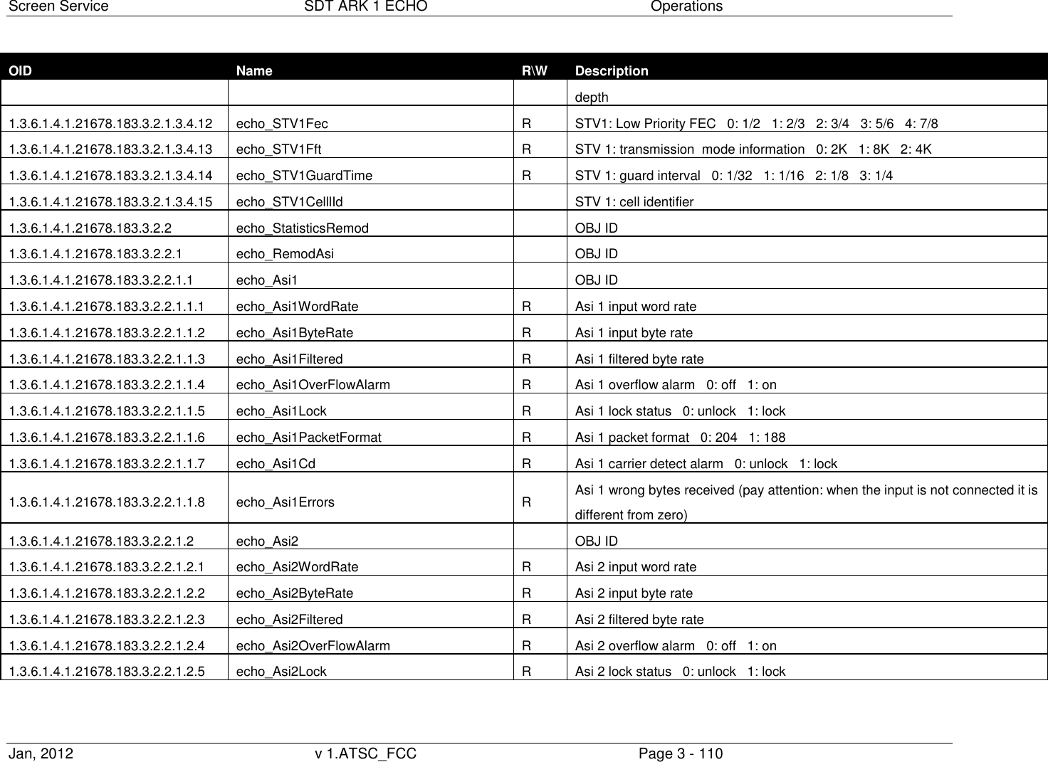
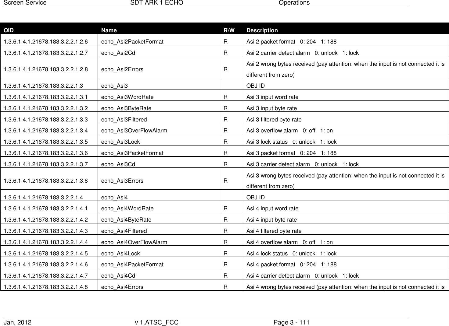
![Screen Service SDT ARK 1 ECHO Operations Jan, 2012 v 1.ATSC_FCC Page 3 - 21 Table 3. Input window Box Parameter / Control Description Admitted Ranges / Values R/H ASI Word rate ASI input word rate. 10 bit word rate of ASI input (Ref. to CEI EN 50083-9). Approximately 27 Mword/s R ASI Bitrate [bit/s] ASI input bitrate. R ASI Filtered bitrate[bit/s] Bitrate actually used by the modulator. Zero when the input is not selected Equal to the total bitrate, when Delete Null Packets disabled Less than total bitrate, when Delete Null Packets enabled R ASI Format Format of received TS Packets (Ref. to CEI EN 50083-9). 188 Bytes 240 Bytes R ASI CD ASI Carrier detect. Green: Detected Grey: Not detected R ASI Lock ASI lock status. The input Transport Stream is unlocked when more than two consecutive Sync Byte are missed then five consecutive Sync Bytes must occur to regain the lock (Ref. to ETSI ETR-291) Green: Locked Grey: Not locked R ASI Overflow ASI input overflow indicator. This alarm condition occurs when the input bitrate exceeds the capability of the modulation (Ref. to ETSI EN 300 744). Red: Alarm Grey: No alarms R](https://usermanual.wiki/Screen-Service-Broadcasting-Technologies/STDX-ARK-ECHO/User-Guide-1622747-Page-48.png)
![Screen Service SDT ARK 1 ECHO Operations Jan, 2012 v 1.ATSC_FCC Page 3 - 22 Box Parameter / Control Description Admitted Ranges / Values R/H ASI Word Errors Total amount of ASI wrong words received. R RTP Protocol Ethernet input packets protocol. UDP RTP R RTP Bitrate [bit/s] Bitrate of TS from Ethernet input. R RTP Filtered bitrate[bit/s] Bitrate actually used by the modulator. Zero when the input is not selected Equal to the total bitrate, when Delete Null Packets disabled Less than total bitrate, when Delete Null Packets enabled R RTP Format Format of received TS Packets (Ref. to CEI EN 50083-9). 188 Bytes 240 Bytes R RTP Lock TS lock status. The input Transport Stream is unlocked when more than two consecutive Sync Byte are missed then five consecutive Sync Bytes must occur to regain the lock (Ref. to ETSI ETR-291) Green: Locked Grey: Not locked R RTP Sequence error Ethernet input Sequence error alarm status. This alarm condition occurs when an error in the sequence of input packets at IP level occurs. Red: Alarm Grey: No alarms R](https://usermanual.wiki/Screen-Service-Broadcasting-Technologies/STDX-ARK-ECHO/User-Guide-1622747-Page-49.png)
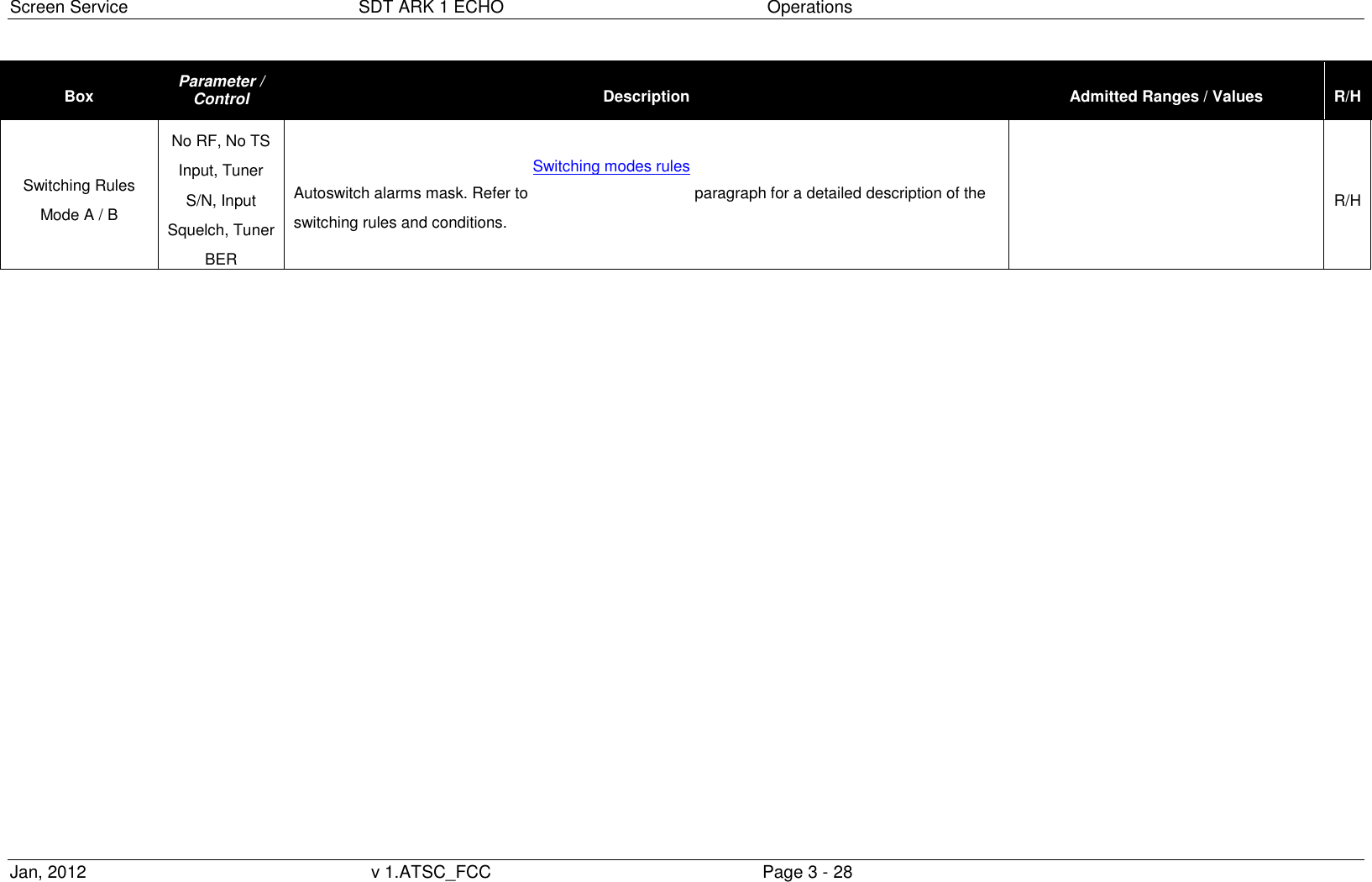
![Screen Service SDT ARK 1 ECHO Operations Jan, 2012 v 1.ATSC_FCC Page 3 - 26 Box Parameter / Control Description Admitted Ranges / Values R/H System Mode & Autoswitching Frequency Error [Hz] Frequency error automatically corrected. Note: When the frequency error exceeds the dynamics, STV might loose the lock. Out of range: input frequency error exceeds 166 KHz dynamics. Set a +/- 166 KHz input freq. offset in order to true up the dynamics. Min: -83 KHz Max: +83KHz R/H System Mode & Autoswitching Automatic Freq. Control Shows Automatic Freq. Control status. Enabled Disabled R/H Mode A / Mode B S/N Thr [dBm] Signal to Noise alarm threshold Min: -10 dBm Max: –50 dBm R/H Mode A / Mode B Automatic Freq. Control Enabling button of the AFC (refer to Appendix A for further information) Enabled Disabled R/H Mode A / Mode B Mode A / B Selector of working mode. Three different working modes are provided: Analog Television Heterodyne Transposer; Digital Television Heterodyne Transposer; Re-broadcasting ATSC Modulator. Rep. Analog Rep. Digital Tx ATSC R/H](https://usermanual.wiki/Screen-Service-Broadcasting-Technologies/STDX-ARK-ECHO/User-Guide-1622747-Page-53.png)
![Screen Service SDT ARK 1 ECHO Operations Jan, 2012 v 1.ATSC_FCC Page 3 - 27 Box Parameter / Control Description Admitted Ranges / Values R/H Mode A / Mode B Channel Selector of the UHF input channel used as RF input. Min: 21 Max: 69 R/H Mode A / Mode B Offset [Hz] Frequency offset from the channel center frequency of the RF input. 1 Hz step variation. Min: -4 MHz Max: 4 MHz R/H Mode A / Mode B Squelch [dBm] Squelch alarm threshold expressed in dBm. Input is squelched when the RF level is under this treshold. Min: -70 Max: -20 R/H Mode A / Mode B Input HP Selector of TS input for re-modulator used for Not Hierarchical or High Priority. ASI 0 ASI 1 ASI 2 ASI 3 RX.HP RX.LP GbE1 GbE2 R Mode A / Mode B Input LP Selector of TS input for re-modulator used for Low Priority in a Hierarchical Modulation. R](https://usermanual.wiki/Screen-Service-Broadcasting-Technologies/STDX-ARK-ECHO/User-Guide-1622747-Page-54.png)
![Screen Service SDT ARK 1 ECHO Operations Jan, 2012 v 1.ATSC_FCC Page 3 - 31 Table 6. Tuner management Box Parameter / Control Description Admitted Ranges / Values R/H Tuner Stat Bitrate [bit/s] Bitrate of TS from RF input (HP and LP). R/H Tuner Stat Filtered [bit/s Bitrate actually used by the modulator. Zero when the input is not selected Equal to the total bitrate, when Delete Null Packets disabled Less than total bitrate, when Delete Null Packets enabled R/H Tuner Stat Lock HP/LP input lock status. The input Transport Stream is locked when no more than two consecutive Sync Byte are missed. Green: Locked Grey: Not locked R/H Tuner Stat Overflow HP/LP input overflow alarm status. This alarm condition occurs when the input bitrate exceeds the capability of the modulation (Ref. to ETSI EN 300 744). Red: Alarm Grey: No alarms R/H Turner Main Rx level RF input rx level. R/H Turner Main BER Threshold Demodulator Bit Error Rate alarm threshold. Min: 0.000001 Max: 0.06 R/H Turner Main BER Threshold Demodulator Bit Error Rate alarm threshold. Min: 0.000001 Max: 0.06 R/H](https://usermanual.wiki/Screen-Service-Broadcasting-Technologies/STDX-ARK-ECHO/User-Guide-1622747-Page-58.png)
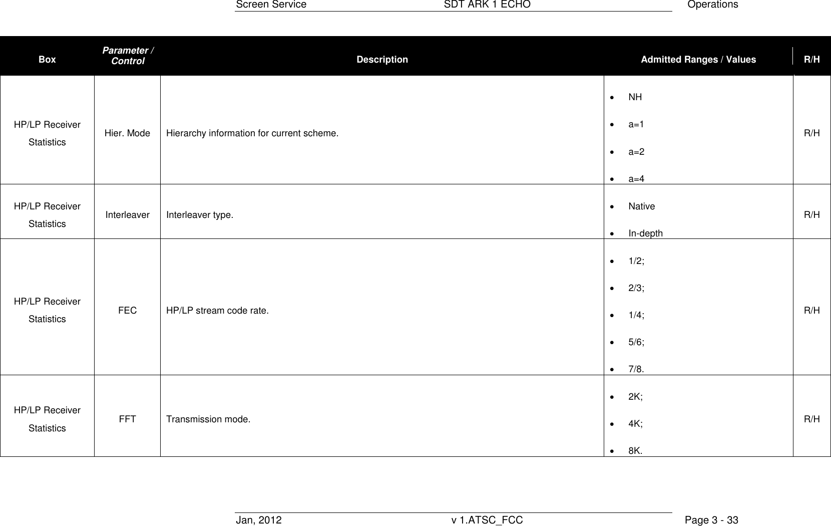
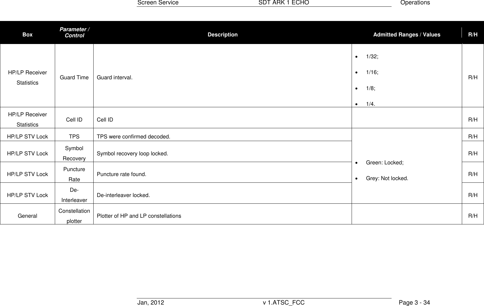
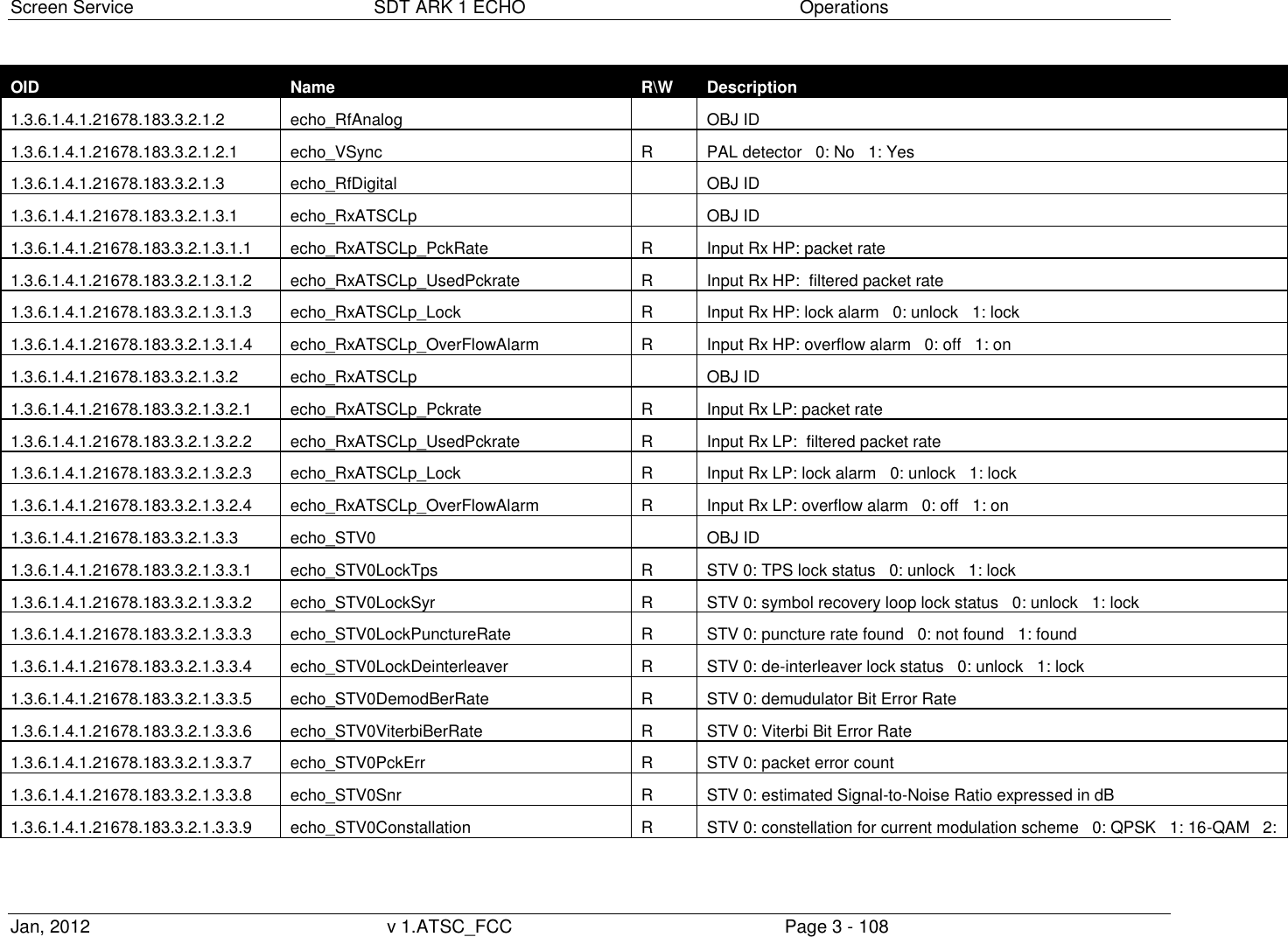
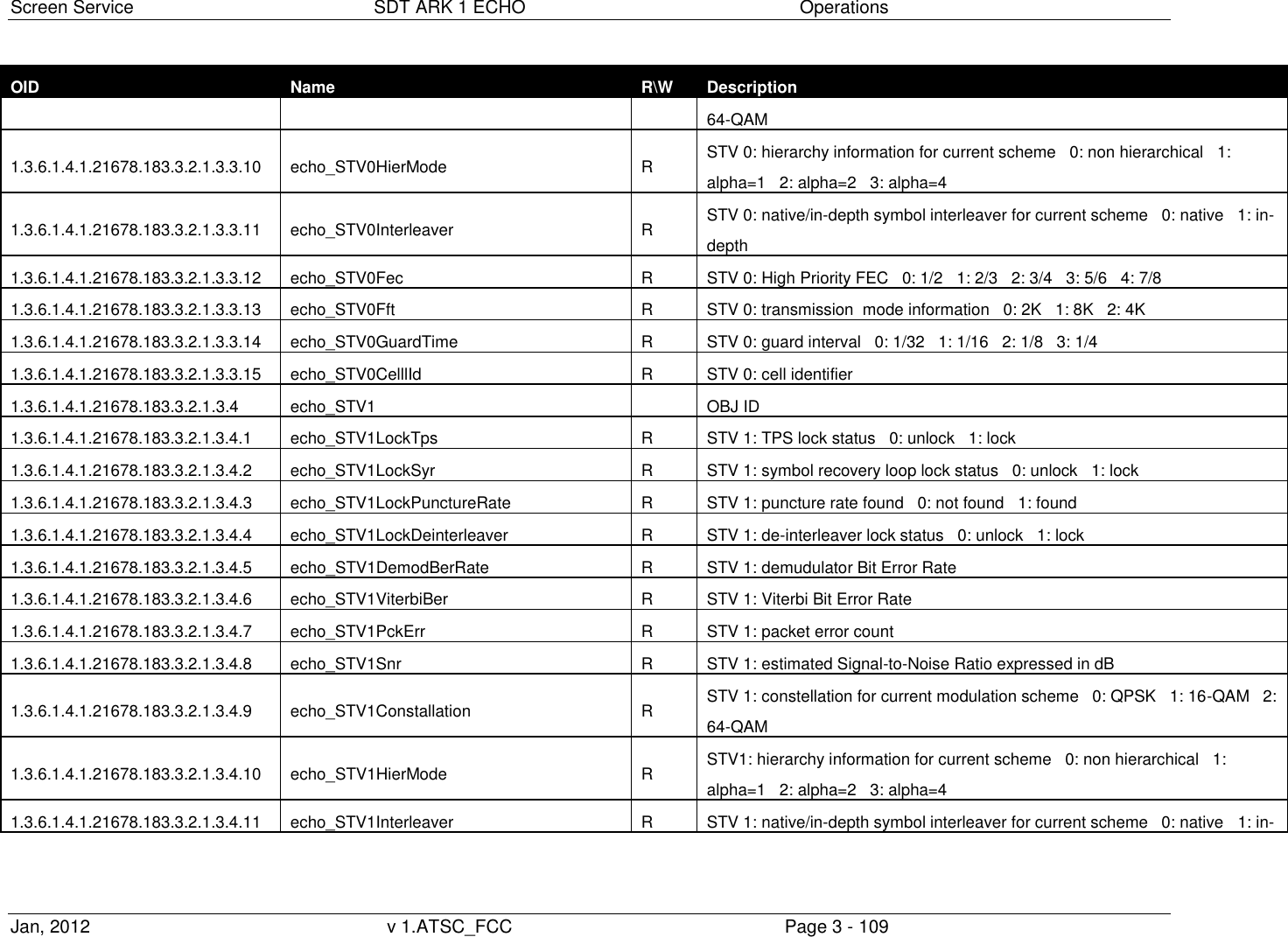
![Screen Service SDT ARK 1 ECHO Operations Jan, 2012 v 1.ATSC_FCC Page 3 - 32 Box Parameter / Control Description Admitted Ranges / Values R/H Turner Main Squelch alarm Squelch alarm status. Red: Alarm Grey: No alarms R/H Turner Main V Sync Analog signal lock status. The PAL detector has been implemented through the detection of the video carrier synchronization at 15,625 Hz. Green: Good Analog Grey: Bad Analog R/H HP/LP Receiver Statistics Demodulator BER Demodulator bit error rate. R/H HP/LP Receiver Statistics Viterbi BER Viterbi byte error rate. R/H HP/LP Receiver Statistics Packet Error Packet error counter. R/H HP/LP Receiver Statistics SNR [dB] Signal to Noise Ratio. R/H HP/LP Receiver Statistics Constellation Constellation for current modulation scheme.. QPSK 16-QAM 64-QAM R/H](https://usermanual.wiki/Screen-Service-Broadcasting-Technologies/STDX-ARK-ECHO/User-Guide-1622747-Page-59.png)
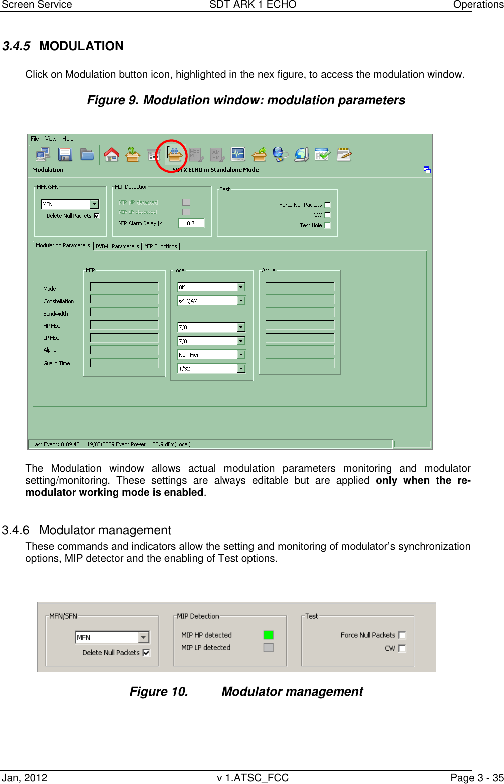
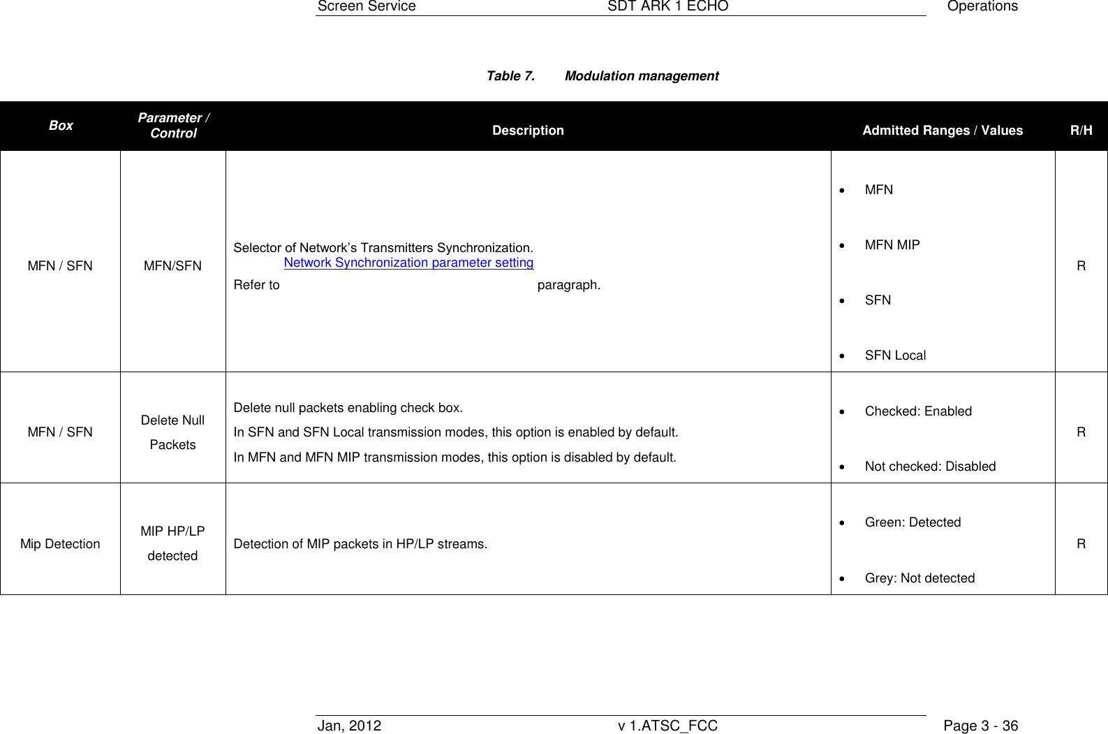
![Screen Service SDT ARK 1 ECHO Operations Jan, 2012 v 1.ATSC_FCC Page 3 - 37 Box Parameter / Control Description Admitted Ranges / Values R/H Mip Detection MIP Alarm Delay [s] Time to wait for No MIP alarm rising expressed in seconds (refer to Alarms paragraph). Note: It is highly recommended to set a MIP Alarm Delay value different from zero as to allow the input signal locking. Min: 1 s Max: 25.5 s R Test Force Null Packets Null data packets transmission enabling check box. Checked: Enabled Not checked: Disabled R Test CW CW test enabling check box. Checked: Enabled Not checked: Disabled R/H Test Test Hole Test Hole enabling check box. Checked: Enabled Not checked: Disabled R/H](https://usermanual.wiki/Screen-Service-Broadcasting-Technologies/STDX-ARK-ECHO/User-Guide-1622747-Page-64.png)
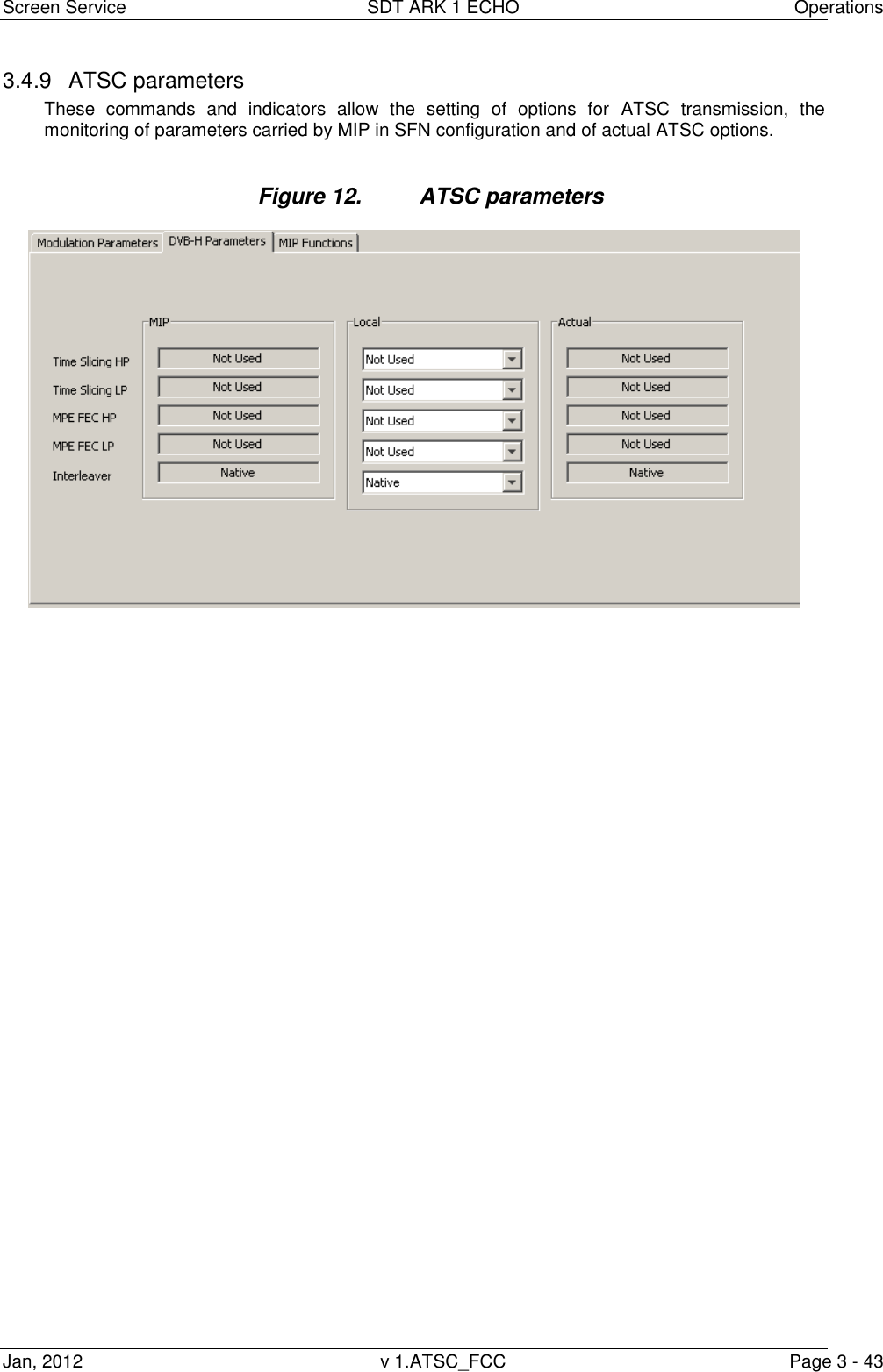
![Screen Service SDT ARK 1 ECHO Operations Jan, 2012 v 1.ATSC_FCC Page 3 - 46 Table 11. MIP function Modulation window: MIP functions Box Parameter / Control Description Admitted Ranges / Values R/H MIP Cell Id enable MIP cell ID function enabling Checked: Enabled Not checked: Disabled R Local General Cell Id enabling. Must be enabled to insert Cell Id into output TPS. R MIP Cell ID MIP cell ID monitoring. R Local Local Cell ID setting. Min: 0 Max: 65,535 R Actual Used Cell ID monitoring. R MIP Max Delay [100ns] MIP max delay function monitoring Min: 0 Max: 9,999,999 R Local User delay setting. R Actual Used delay monitoring. R MIP Freq. Offset [Hz] MIP frequency offset function enabling and monitoring Checked: Enabled Not checked: Disabled R](https://usermanual.wiki/Screen-Service-Broadcasting-Technologies/STDX-ARK-ECHO/User-Guide-1622747-Page-73.png)
![Screen Service SDT ARK 1 ECHO Operations Jan, 2012 v 1.ATSC_FCC Page 3 - 47 Box Parameter / Control Description Admitted Ranges / Values R/H Local User frequency offset setting. Min: -500,000 Hz Max: 500,000 Hz R Actual Used frequency offset monitoring. R MIP Time Offset [100ns] MIP time offset function enabling and monitoring Checked: Enabled Not checked: Disabled R Local User time offset setting. Min: -32,768 Max: 32,767 R Actual Used time offset monitoring. R MIP Tx Power [0.1dB] NOT IMPLEMENTED (MIP Tx power function enabling and monitoring). Checked: Enabled Not checked: Disabled R](https://usermanual.wiki/Screen-Service-Broadcasting-Technologies/STDX-ARK-ECHO/User-Guide-1622747-Page-74.png)
![Screen Service SDT ARK 1 ECHO Operations Jan, 2012 v 1.ATSC_FCC Page 3 - 49 Box Parameter / Control Description Admitted Ranges / Values R/H Local Tx ID Broadcast Enable Tx ID 0 enabling. Checked: Enabled Not checked: Disabled R Local Tx ID User Tx ID setting. Min: 0 Max: 65,535 R Local Standard User transmission standard setting. ATSC o Checked: Enabled o Not checked: Disabled ATSC o Checked: Enabled o Not checked: Disabled R Actual Center Freq. [Hz] Used center frequency indicator. R](https://usermanual.wiki/Screen-Service-Broadcasting-Technologies/STDX-ARK-ECHO/User-Guide-1622747-Page-76.png)
![Screen Service SDT ARK 1 ECHO Operations Jan, 2012 v 1.ATSC_FCC Page 3 - 50 Box Parameter / Control Description Admitted Ranges / Values R/H Actual Network Delay [100ns] Used network delay indicator. R Table 12. s](https://usermanual.wiki/Screen-Service-Broadcasting-Technologies/STDX-ARK-ECHO/User-Guide-1622747-Page-77.png)
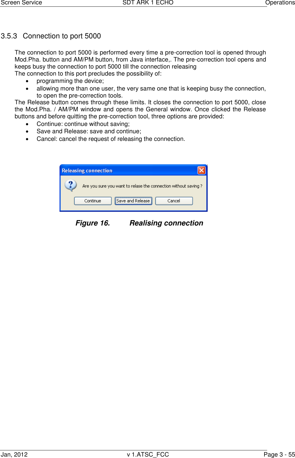
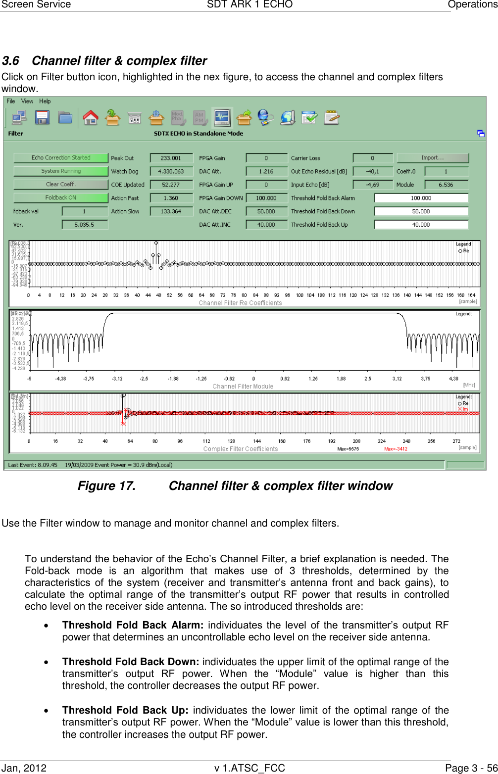
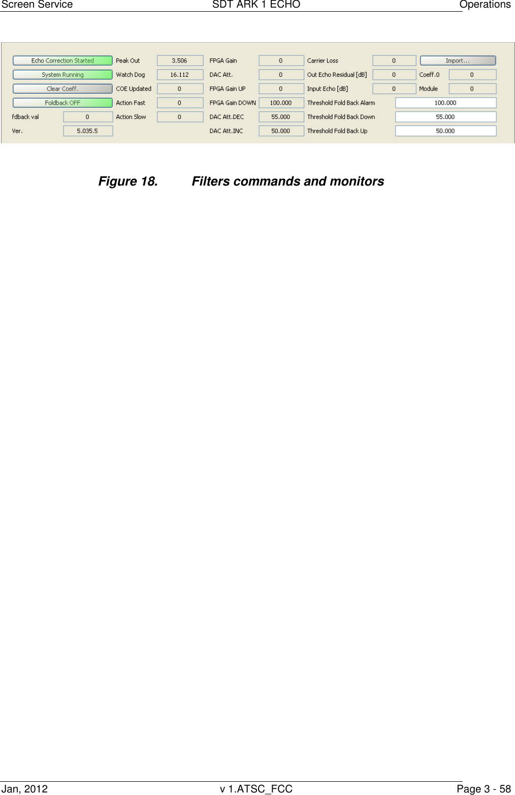
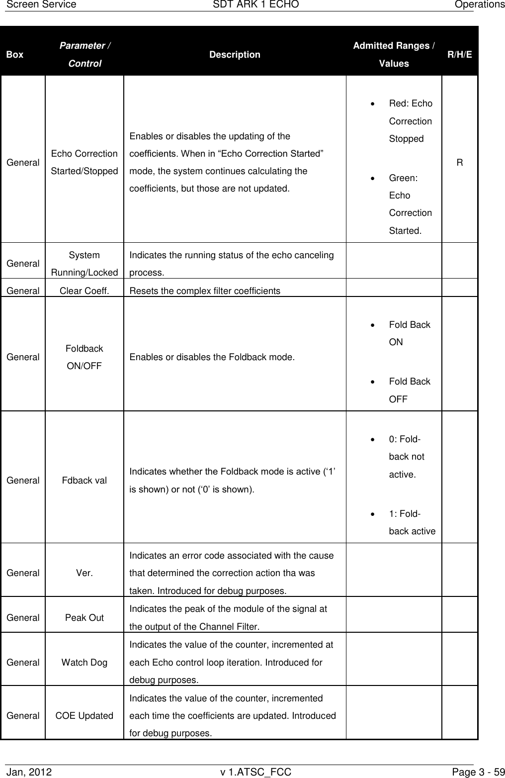
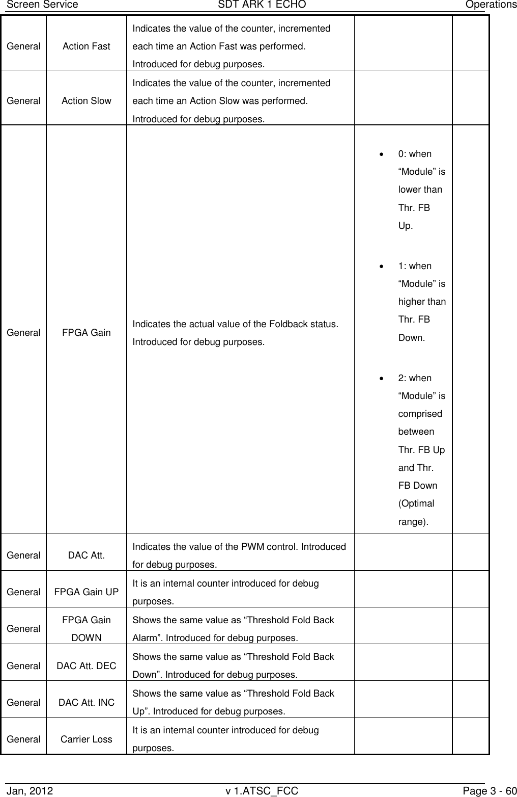
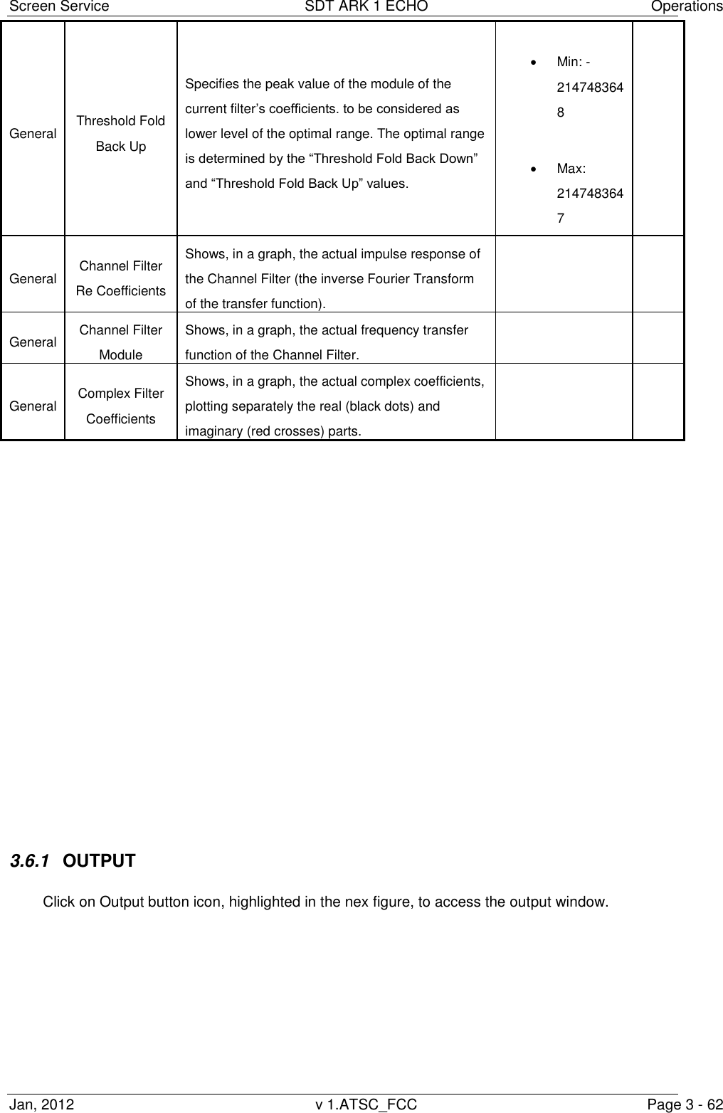
![Screen Service SDT ARK 1 ECHO Operations Jan, 2012 v 1.ATSC_FCC Page 3 - 61 General Out Echo Residual [dB] Indicates the value of the Echo amplitude that was not compensated. General Input Echo [dB] Indicates the value of the Echo amplitude that was compensated. General Import… Imports the “.echf” file that contains the channel filter coefficients. R General Coeff.0 Shows the same value as “fdback val” indicator. Introduced for debug purposes. R General Module Shows the peak value of the module of the current filter‟s coefficients. Min: -2147483648 Max: 2147483647 General Threshold Fold Back Alarm Specifies the peak value of the module of the current filter‟s coefficients. to be considered as alarm level. The output RF power shall always be lower than this threshold. Min: -2147483648 Max: 2147483647 R General Threshold Fold Back Down Specifies the peak value of the module of the current filter‟s coefficients. to be considered as higher level of the optimal range. The optimal range is determined by the “Threshold Fold Back Down” and “Threshold Fold Back Up” values. Min: -2147483648 Max: 2147483647 R](https://usermanual.wiki/Screen-Service-Broadcasting-Technologies/STDX-ARK-ECHO/User-Guide-1622747-Page-88.png)
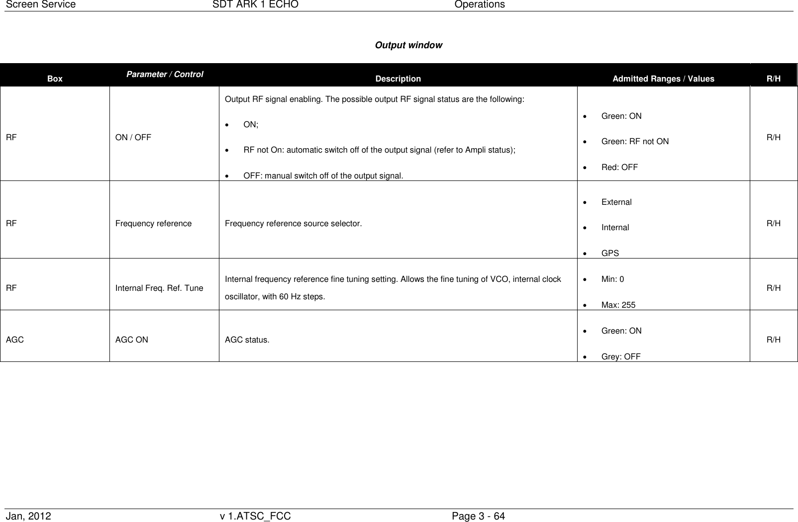
![Screen Service SDT ARK 1 ECHO Operations Jan, 2012 v 1.ATSC_FCC Page 3 - 65 Box Parameter / Control Description Admitted Ranges / Values R/H AGC Mode Current AGC mode indicator. Analog/Digital: o Green: ON o Grey: OFF R/H Frequency Out [Hz] Frequency Out [Hz] Output center frequency expressed in Hz. Status Ampli status Current amplifier status indicator. On Off Restart Stand-by off Init Alarm off Rf off Opto off R/H Status 28V PSU 28V indicator (values are expressed in V). R/H Status Current PSU 28V [A] PSU 28V current indicator (values are expressed in A). R/H](https://usermanual.wiki/Screen-Service-Broadcasting-Technologies/STDX-ARK-ECHO/User-Guide-1622747-Page-92.png)
![Screen Service SDT ARK 1 ECHO Operations Jan, 2012 v 1.ATSC_FCC Page 3 - 66 Box Parameter / Control Description Admitted Ranges / Values R/H Status 28V / 42V PSU voltage indicator (values are expressed in V). It depends on the hardware type of the device: 28V for SDTx_Echo 20W and 50W; 42V for SDTx_Echo 200W. R/H Status Case Temperature Case temperature indicator (values are expressed in °C). R/H Status Case Temperature 2 2nd Case temperature indicator (values are expressed in °C). Only in SDTX 200 version. Status PSU Temperature PSU temperature indicator (values are expressed in °C). R/H Status Fan 1 Fan 1 speed indicator (values are expressed in rpm). R/H Status Fan 2 Fan 2 speed indicator (values are expressed in rpm). R/H Status Fan 3 Fan 3 speed indicator (values are expressed in rpm). Only in SDTX 200 version. R/H Status Fan 4 Fan 4 speed indicator (values are expressed in rpm). Only in SDTX 200 version. R/H Status FWD Power [dBm] Output forward power indicator (values are expressed in dBm). R/H Status Reflex Power [dBm] Output reflex power indicator (values are expressed in dBm). R/H Opto & Relay Relay 0 Selector of Relay 0 mode. Alarm: indicator of an alarm condition Mode: indicator of operating mode R/H](https://usermanual.wiki/Screen-Service-Broadcasting-Technologies/STDX-ARK-ECHO/User-Guide-1622747-Page-93.png)
![Screen Service SDT ARK 1 ECHO Operations Jan, 2012 v 1.ATSC_FCC Page 3 - 67 Box Parameter / Control Description Admitted Ranges / Values R/H Opto & Relay Relay 0…3 Relays status indicators. Green: Alarm on/Mode A Grey: Alarm off/Mode B R/H Opto&Relay Opto 0…3 Opto status indicators. Optos are normally opened: Opto 0: RF Off, manual switching off of output RF; Opto 1: Mode A/B switch; Opto 2: Retry of amplifier alarms (only in SDTX 200 version); Opto 3: Stand-by enabling; it puts the device on stand-by. Green: Closed (0) Grey: Opened (1) R/H Mode A / Mode B Channel Output channel. Min: 21 Max: 69 R/H Mode A / Mode B Power [dBm] Output power (expressed in dBm). Analog min: 23 dBm Analog max: 43 dBm Digital min: 17 dBm Digital max: 37 dBm R/H Mode A / Mode B Power [W] Output power (expressed in W). R/H](https://usermanual.wiki/Screen-Service-Broadcasting-Technologies/STDX-ARK-ECHO/User-Guide-1622747-Page-94.png)
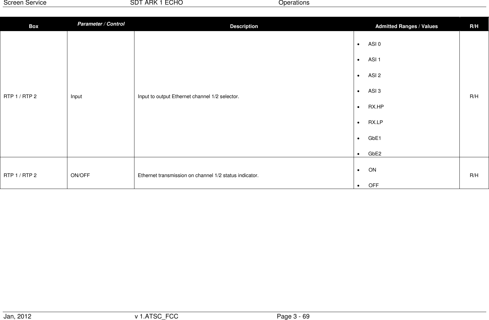
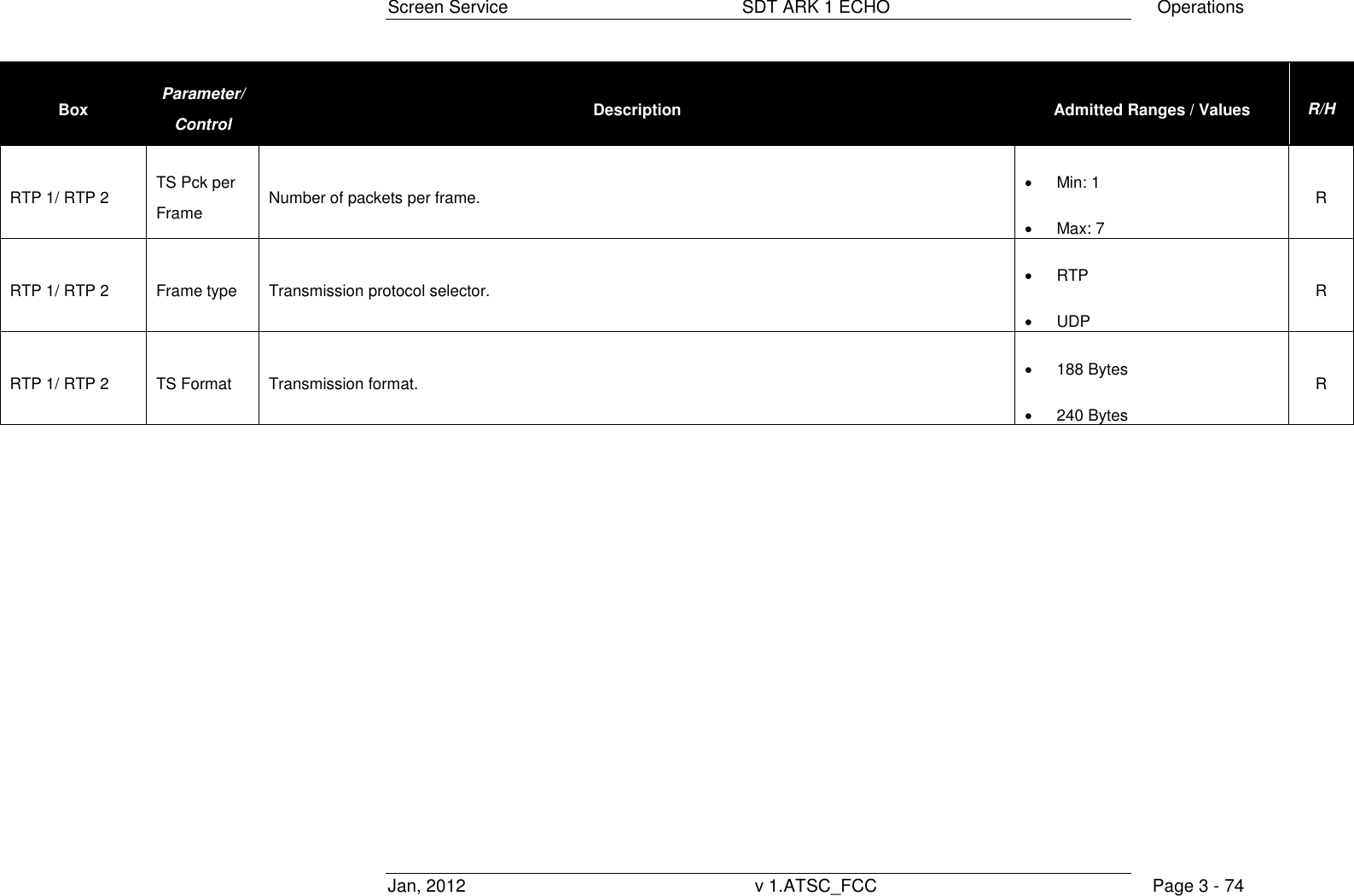
![Screen Service SDT ARK 1 ECHO Operations Jan, 2012 v 1.ATSC_FCC Page 3 - 68 Box Parameter / Control Description Admitted Ranges / Values R/H Mode A / Mode B Offset [Hz] Output frequency offset (expressed in Hz). Min: -4 MHz Max: 4 MHz R/H FWD Power Thresholds Warning [dB] Forward power warning threshold expressed in dBm. Min: -16 dBm Max: 0 dBm R/H FWD Power Thresholds Alarm [dB] Forward power alarm threshold expressed in dBm. R/H Temperature Thresholds Warning Case temperature warning threshold expressed in °C. Min: 0 °C Max: 100 °C R/H Temperature Thresholds Alarm Case temperature alarm threshold expressed in °C. R/H RTP 1 / RTP 2 Enable send frame Channel 1/2 Ethernet transmission enabling. Enabled Disabled R/H](https://usermanual.wiki/Screen-Service-Broadcasting-Technologies/STDX-ARK-ECHO/User-Guide-1622747-Page-95.png)
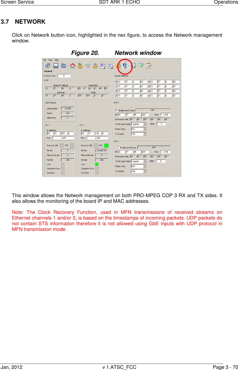
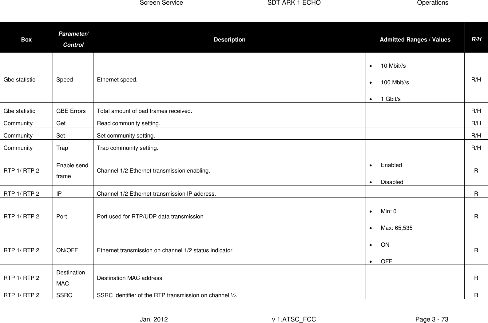
![Screen Service SDT ARK 1 ECHO Operations Jan, 2012 v 1.ATSC_FCC Page 3 - 71 Table 13. Network window Box Parameter/Control Description Admitted Ranges / Values R/H Local Board IP address Board IP address. R/H Local Board MAC address Board MAC address. R/H Local Gateway Gateway address. R/H Local Mask Net Mask. R/H Local Tx Source Port Board receiving port. Min: 0 Max: 65,535 R/H Trap IP address 0…7 Trap 0…7 destination IP address. R/H Rx 1 / Rx 2 IP Address Channel 1/2 receiving IP address. R Rx 1 / Rx 2 Port Channel 1/2 receiving port. Min: 0 Max: 65,535 R Rx 1 / Rx 2 Protocol Ethernet input packets protocol. UDP RTP R Rx 1 / Rx 2 Bitrate [bit/s] Bitrate of TS from Ethernet input. R](https://usermanual.wiki/Screen-Service-Broadcasting-Technologies/STDX-ARK-ECHO/User-Guide-1622747-Page-98.png)
![Screen Service SDT ARK 1 ECHO Operations Jan, 2012 v 1.ATSC_FCC Page 3 - 72 Box Parameter/Control Description Admitted Ranges / Values R/H Rx 1 / Rx 2 Filtered bitrate[bit/s] Bitrate actually used by the modulator. Zero when the input is not selected Equal to the total bitrate, when Delete Null Packets disabled Less than total bitrate, when Delete Null Packets enabled R Rx 1 / Rx 2 Format Received transmission format. 188 Bytes 240 Bytes R Rx 1 / Rx 2 Lock Ethernet input lock status indicator. The input Transport Stream is locked when no more than two consecutive Sync Byte are missed. Green: Lock Grey: Not locked R Rx 1 / Rx 2 Sequence error Ethernet input Sequence error alarm status indicator. This alarm condition occurs when a sequence error occurs Red: Error Grey: No errors R Rx 1 / Rx 2 Overflow Input GbE overflow alarm status. This alarm condition occurs when the input bitrate exceeds the capability of the modulation (Ref. to ETSI EN 300 744). Red: Alarm on Grey: Alarm off R Gbe statistic GBE Packets Total amount of good frames received. R/H](https://usermanual.wiki/Screen-Service-Broadcasting-Technologies/STDX-ARK-ECHO/User-Guide-1622747-Page-99.png)
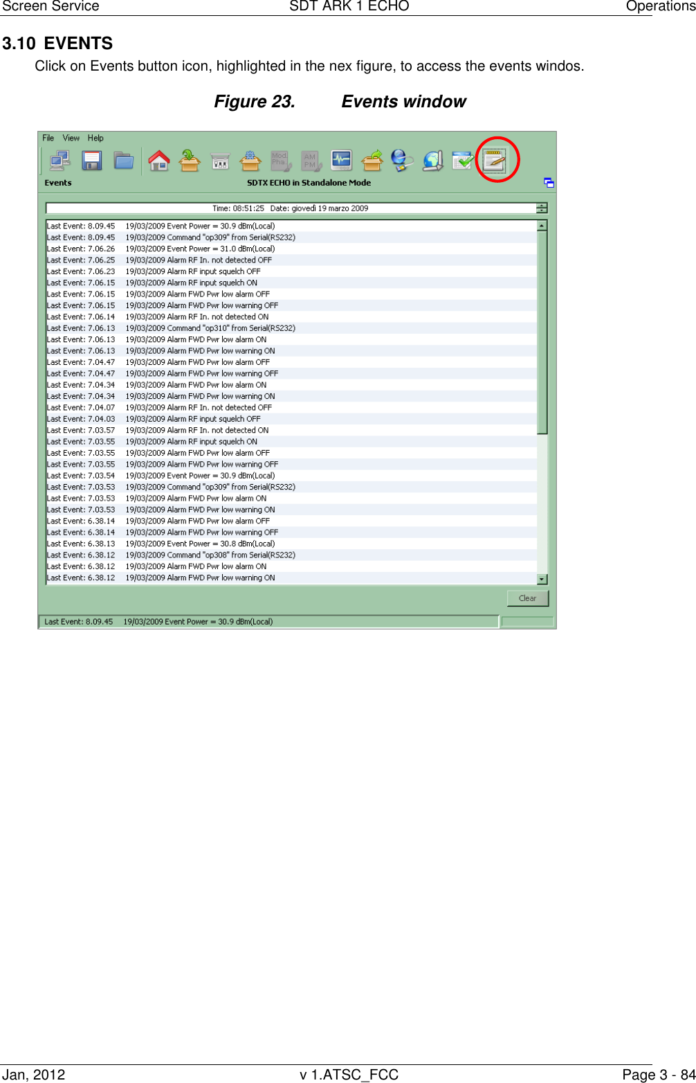
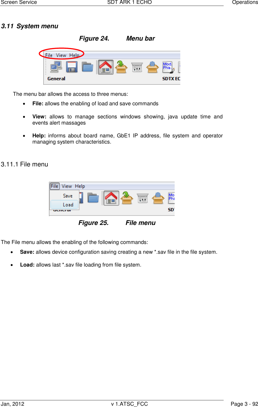
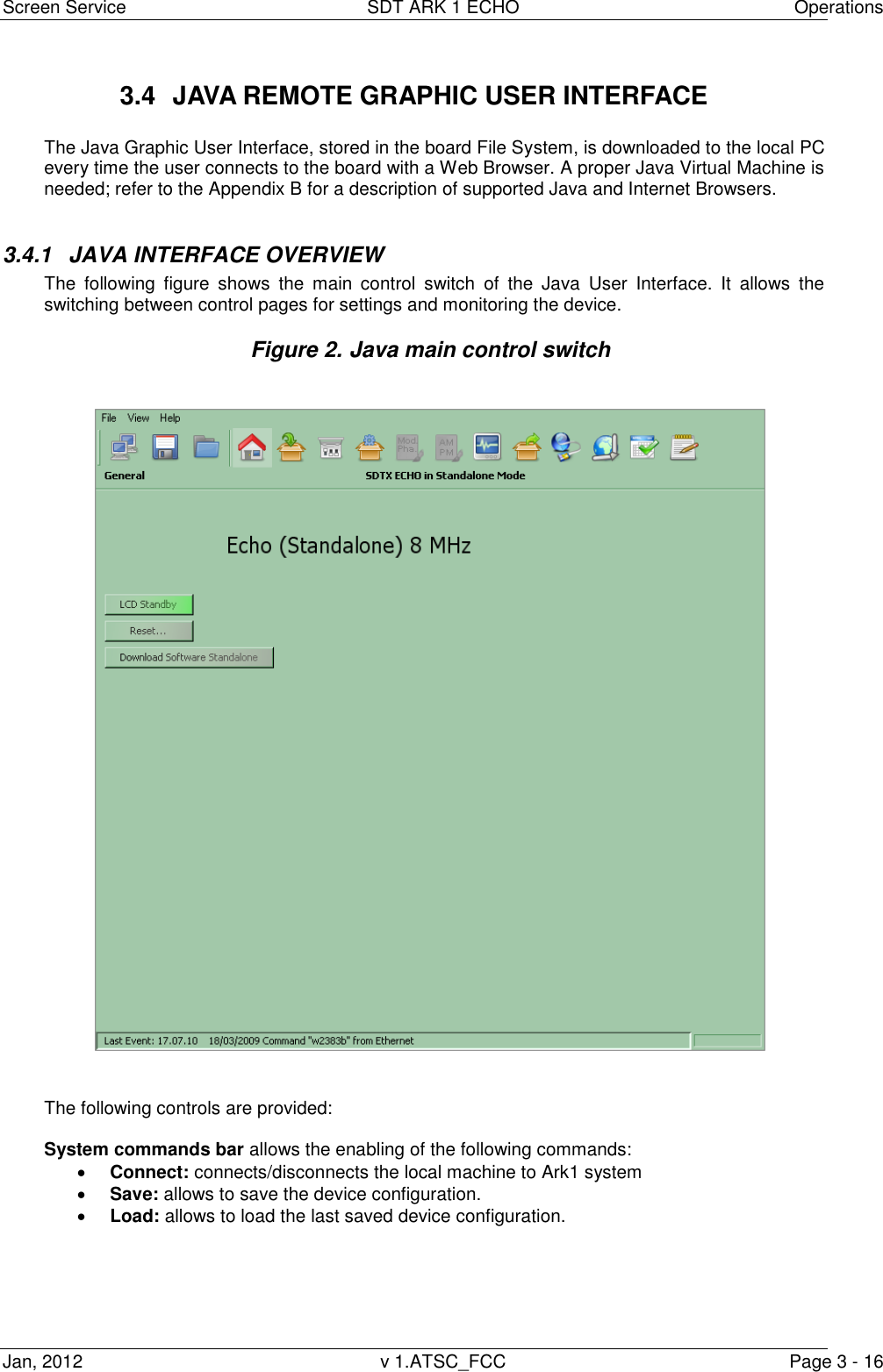
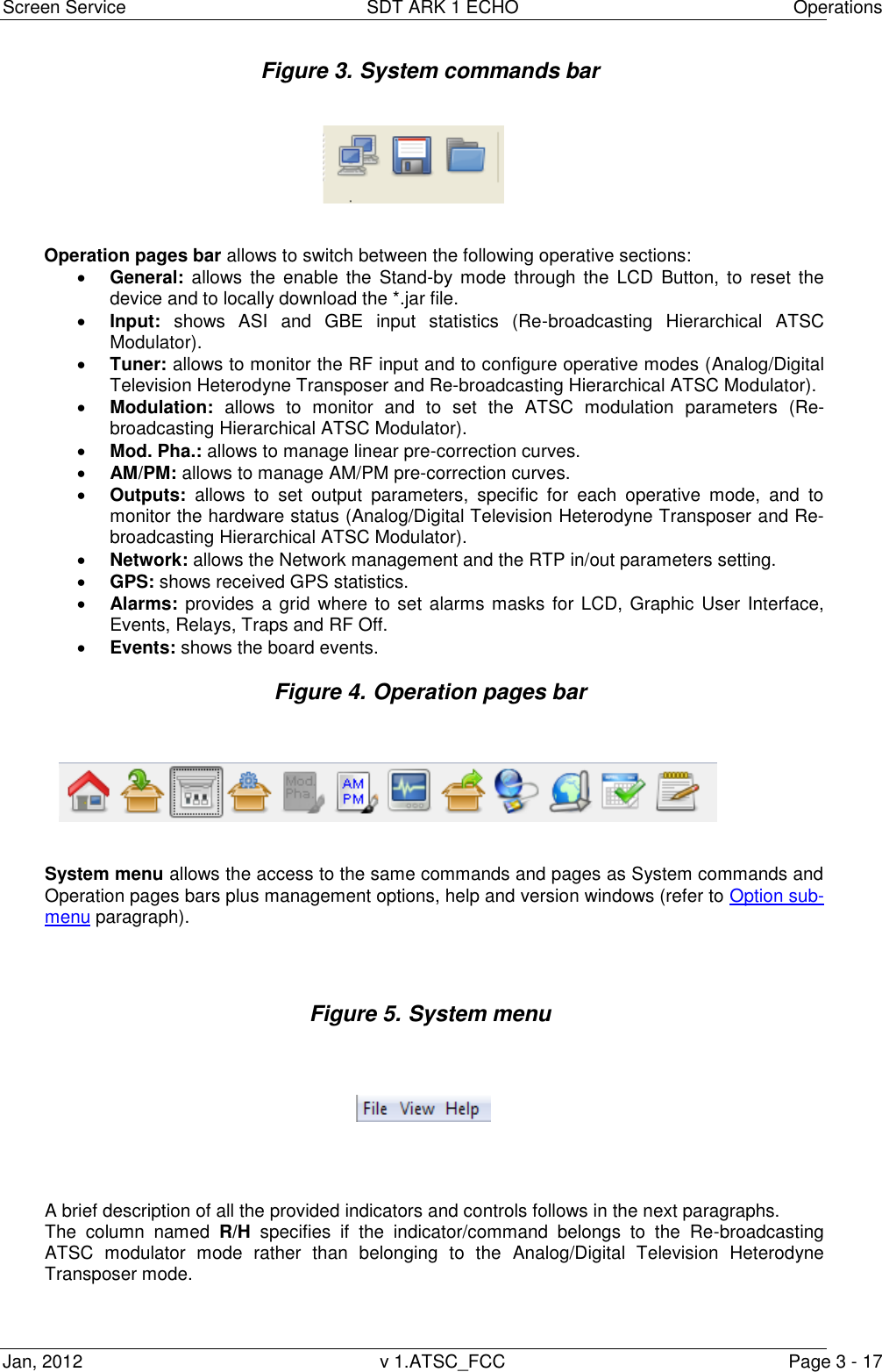
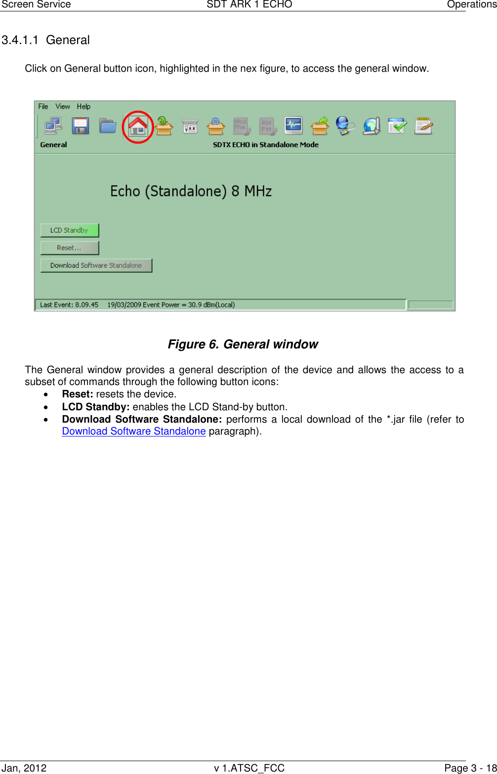
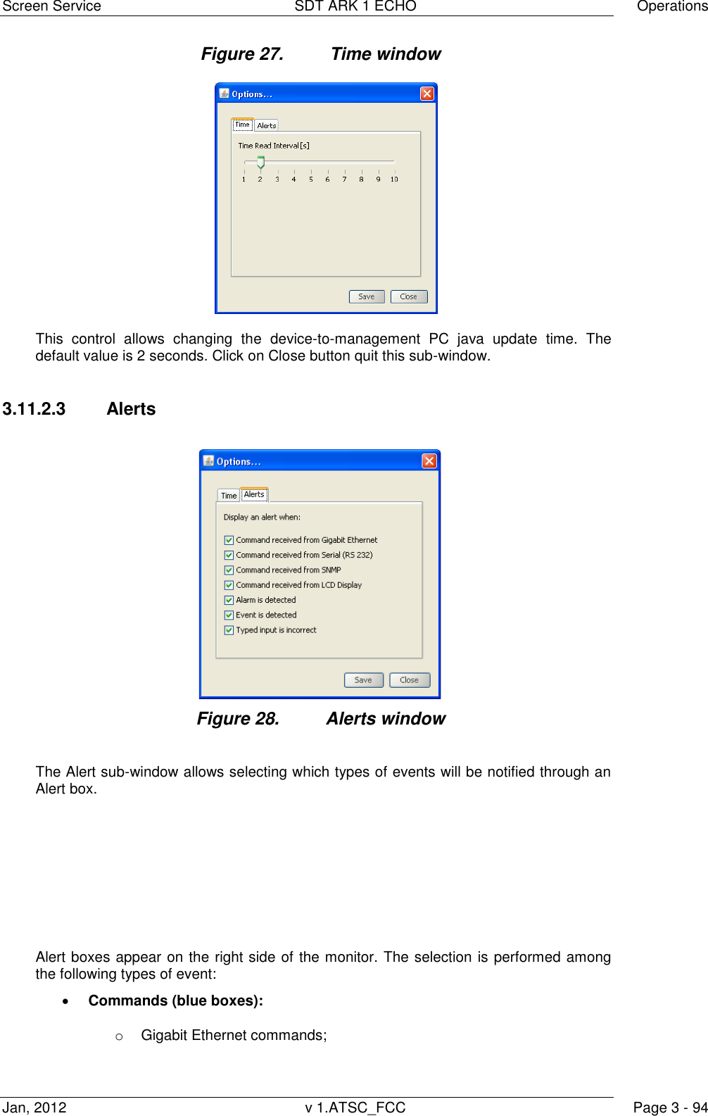
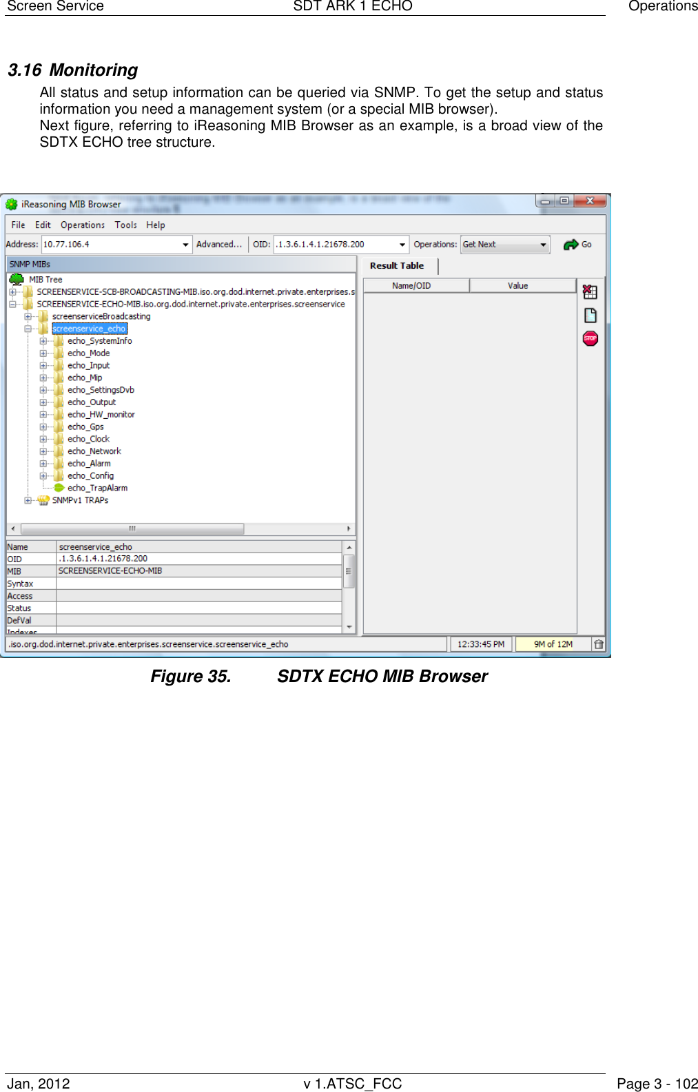
![Screen Service SDT ARK 1 ECHO Operations Jan, 2012 v 1.ATSC_FCC Page 3 - 93 3.11.2 View menu Figure 26. View menu The View menu allows the enabling of the following commands: General: allows to access the general window. Input: allows to access the input window. Tuner: allows to access the Tuner window. Output: allows to access the Output window. Network: allows to access the Network window. CAM: allows to access the PID manager window. Input GPS: allows to access the Input GPS window. Alarms: allows to access the Alarms window. Events: allows to access the Events window. Options: allows to access the Options sub-menu. 3.11.2.1 Option sub-menu The Option sub-menu allows two controls type: Time: Time Read Interval [s]; Alerts: the selection of events to display. Click on the Save button to save Java options; a *.properties file will be created. The device is not loaded with a factory default *.properties file, but it is created and then stored in System File once the properties have been saved. 3.11.2.2 Time](https://usermanual.wiki/Screen-Service-Broadcasting-Technologies/STDX-ARK-ECHO/User-Guide-1622747-Page-120.png)
![Screen Service SDT ARK 1 ECHO Operations Jan, 2012 v 1.ATSC_FCC Page 3 - 100 3.14 SNMP Protocol Preferences Go to SNMP Protocol Preferences. The following parameters should be set in order to correctly configure the SNMP Manager: SNMP protocol version: SNMPv1; Read Community: the same of the one set in the Get field of Java interface, community section; Set Community: the same of the one set in the Set field of Java interface, community section; Timeout [s]: user defined; Retransmits: user defined; Port number: 161. Next figure illustrates how to configure SNMP Protocol Preferences using MG_SOFT MIB Browser as an example. Figure 3.13-1: SNMP Protocol Preferences](https://usermanual.wiki/Screen-Service-Broadcasting-Technologies/STDX-ARK-ECHO/User-Guide-1622747-Page-127.png)
![Screen Service SDT ARK 1 ECHO Operations Jan, 2012 v 1.ATSC_FCC Page 3 - 113 OID Name R\W Description 1.3.6.1.4.1.21678.183.4.1.2 echo_DetectLp R Low priority MIP detect 0: not detected 1: detected 1.3.6.1.4.1.21678.183.4.2 echo_MipTxId OBJ ID 1.3.6.1.4.1.21678.183.4.2.1 echo_TxId RW Transmitter identifier 1.3.6.1.4.1.21678.183.4.2.2 echo_TxId0Enable RW TX ID 0 enable 0: disabled 1: enabled 1.3.6.1.4.1.21678.183.4.3 echo_MipConstallation R MIP Constellation 0: QPSK 1: 16-QAM 2: 64-QAM 1.3.6.1.4.1.21678.183.4.4 echo_MipInterleaver R MIP native/in-depth symbol interleaver selector 0: native 1: in-depth 1.3.6.1.4.1.21678.183.4.5 echo_MipAlpha R MIP alpha 0: not hierarchical 1: alpha=1 2: alpha=2 3: alpha=4 1.3.6.1.4.1.21678.183.4.6 echo_MipGuardTime R MIP guard interval 0:1/32 1:1/16 2:1/8 3:1/4 1.3.6.1.4.1.21678.183.4.7 echo_MipFft R MIP transmission mode 0:2K 1:8K 2:4K 1.3.6.1.4.1.21678.183.4.8 echo_MipBandwidth R MIP bandwidth 0: 7MHz 1: 8MHz 2: 6MHz 3: 5MHz 1.3.6.1.4.1.21678.183.4.9 echo_MipFec OBJ ID 1.3.6.1.4.1.21678.183.4.9.1 echo_MipFecHp R MIP High priority FEC 0: 1/2 1: 2/3 2: 3/4 3: 5/6 4: 7/8 1.3.6.1.4.1.21678.183.4.9.2 echo_MipFecLp R MIP Low priority FEC 0: 1/2 1: 2/3 2: 3/4 3: 5/6 4: 7/8 1.3.6.1.4.1.21678.183.4.10 echo_MipTimeSlicing OBJ ID 1.3.6.1.4.1.21678.183.4.10.1 echo_MipTimeSlicingHp R MIP High priority time slicing 0: not used 1: used 1.3.6.1.4.1.21678.183.4.10.2 echo_MipTimeSlicingLp R MIP Low priority time slicing 0: not used 1: used 1.3.6.1.4.1.21678.183.4.11 echo_MipMpeFec OBJ ID 1.3.6.1.4.1.21678.183.4.11.1 echo_MipMpeFecHp R High priority MPE-FEC 0: not used 1: used 1.3.6.1.4.1.21678.183.4.11.2 echo_MipMpeFecLp R Low priority MPE-FEC 0: not used 1: used 1.3.6.1.4.1.21678.183.4.12 echo_MipDelayTx R MIP transmission delay 1.3.6.1.4.1.21678.183.4.13 echo_MipMaxDelay R MIP maximum delay [100ns] 1.3.6.1.4.1.21678.183.4.14 echo_MipTimeOffset OBJ ID 1.3.6.1.4.1.21678.183.4.14.1 echo_TimeOffsetEnable RW MIP time offset enable](https://usermanual.wiki/Screen-Service-Broadcasting-Technologies/STDX-ARK-ECHO/User-Guide-1622747-Page-140.png)
![Screen Service SDT ARK 1 ECHO Operations Jan, 2012 v 1.ATSC_FCC Page 3 - 114 OID Name R\W Description 1.3.6.1.4.1.21678.183.4.14.2 echo_TimeOffsetStatus R MIP time offset [100ns] 1.3.6.1.4.1.21678.183.4.15 echo_MipFrequencyOffset OBJ ID 1.3.6.1.4.1.21678.183.4.15.1 echo_FrequencyOffsetEnable RW MIP frequency offset enable 0: disabled 1: enabled 1.3.6.1.4.1.21678.183.4.15.2 echo_FrequencyOffsetStatus R MIP frequency offset [Hz] 1.3.6.1.4.1.21678.183.4.16 echo_MipTxPower OBJ ID 1.3.6.1.4.1.21678.183.4.16.1 echo_TxPoweEnable R NOT IMPLEMENTED (MIP transmission power enable 0: disabled 1: enabled) 1.3.6.1.4.1.21678.183.4.16.2 echo_TxPowerStatus R MIP transmission power [0.1 dB] 1.3.6.1.4.1.21678.183.4.17 echo_MipCellId OBJ ID 1.3.6.1.4.1.21678.183.4.17.1 echo_CellIdEnable RW Cell id function enable 0: disabled 1: enabled 1.3.6.1.4.1.21678.183.4.17.2 echo_CellIdFunctionEnable R Enable function status 0: not received 1: received 1.3.6.1.4.1.21678.183.4.17.3 echo_CellIdFunctionTag R Cell id function tag 0: not detected 1: detected 1.3.6.1.4.1.21678.183.4.17.4 echo_CellIdStatus R Cell id function 1.3.6.1.4.1.21678.183.4.17.5 echo_CellIdWaitForEnable R Cell id function wait for enable 0: disabled 1: enabled 1.3.6.1.4.1.21678.183.4.18 echo_MipFunctionBw OBJ ID 1.3.6.1.4.1.21678.183.4.18.1 echo_FunctionBwEnable R NOT IMPLEMENTED (Bandwidth function enable 0: disabled 1: enabled) 1.3.6.1.4.1.21678.183.4.18.2 echo_FunctionBwStatus R Bandwidth function 0: 5MHz 1: reserved for future use 1.3.6.1.4.1.21678.183.4.18.3 echo_FunctionBwEnableRx R Enable function status 0: not received 1: received 1.3.6.1.4.1.21678.183.4.18.4 echo_FunctionChBwTag R Bandwidth function tag 0: not detected 1: detected 1.3.6.1.4.1.21678.183.4.18.5 echo_FunctionChBwWaitForEnable R Channel bandwith function wait for enabled 0: disabled 1: enabled 1.3.6.1.4.1.21678.183.5 echo_SettingsATSC OBJ ID 1.3.6.1.4.1.21678.183.5.1 echo_SettingsCellIdEnable RW Cell Id enable 0: disabled 1: enabled 1.3.6.1.4.1.21678.183.5.3 echo_SettingsTxModeSel OBJ ID](https://usermanual.wiki/Screen-Service-Broadcasting-Technologies/STDX-ARK-ECHO/User-Guide-1622747-Page-141.png)
![Screen Service SDT ARK 1 ECHO Operations Jan, 2012 v 1.ATSC_FCC Page 3 - 117 OID Name R\W Description 1.3.6.1.4.1.21678.183.6.1.3.2.3 echo_Gbe1Enable RW Tx channel 2: transmission enable 0: disabled 1: enabled 1.3.6.1.4.1.21678.183.6.2 echo_OutputRf OBJ ID 1.3.6.1.4.1.21678.183.6.2.1 echo_RfOn RW RF output enable 0: disabled 1: enabled 1.3.6.1.4.1.21678.183.6.2.2 echo_RfStatus R RF output status 0: off 1: on 1.3.6.1.4.1.21678.183.6.2.3 echo_RfPrecCurveMode R Pre-correction curve editing status 0: auto 1: manual 1.3.6.1.4.1.21678.183.6.2.4 echo_RfPrecCurve R Pre-correction curve editing status 0: closed 1: opened 1.3.6.1.4.1.21678.183.6.2.5 echo_RfPrecCurveActualNumber R Current pre-correction curve number 1.3.6.1.4.1.21678.183.6.3 echo_OutputTest OBJ ID 1.3.6.1.4.1.21678.183.6.3.1 echo_TestForceNullPck RW Force null packets 0: disabled 1: enabled 1.3.6.1.4.1.21678.183.6.3.2 echo_TestCw RW Test CW 0: disabled 1: enabled 1.3.6.1.4.1.21678.183.6.3.3 echo_TestHole RW Test Hole 0: disabled 1: enabled 1.3.6.1.4.1.21678.183.6.4 echo_OutputTsProcessing OBJ ID 1.3.6.1.4.1.21678.183.6.4.1 echo_TsProcessingDeleteNullPck RW Delete null packets enable 0: disabled 1: enable 1.3.6.1.4.1.21678.183.6.4.2 echo_TsProcessingPcrRestamping RW PCR restamping enable 0: disabled 1: enable 1.3.6.1.4.1.21678.183.6.5 echo_OutputModulator_monitor OBJ ID 1.3.6.1.4.1.21678.183.6.5.1 echo_modulator_monitor_time_offset R Used time offset [100ns] indicator 1.3.6.1.4.1.21678.183.6.5.2 echo_modulator_monitor_constallation R Used constellation indicator 0: QPSK 1: 16-QAM 2: 64-QAM 1.3.6.1.4.1.21678.183.6.5.3 echo_modulator_monitor_alpha R Used apha indicator 0: not hierarchical 1: alpha=1 2: alpha=2 3: alpha=4 1.3.6.1.4.1.21678.183.6.5.4 echo_modulator_monitor_guard_time R Used guard time indicator 0: 1/32 1: 1/16 2: 1/8 3: 1/4 1.3.6.1.4.1.21678.183.6.5.5 echo_modulator_monitor_fft R Used transmission mode indicator 0:2K 1:8K 2:4K 1.3.6.1.4.1.21678.183.6.5.6 echo_modulator_monitor_bandwidth R Used bandwidth indicator 0: 7MHz 1: 8MHz 2: 6MHz 3: 5MHz 1.3.6.1.4.1.21678.183.6.5.7 echo_modulator_monitor_frequency_center R Center Frequency indicator (expressed in Hz) 1.3.6.1.4.1.21678.183.6.5.8 echo_modulator_monitor_frequency_offset R Used frequency offset indicator](https://usermanual.wiki/Screen-Service-Broadcasting-Technologies/STDX-ARK-ECHO/User-Guide-1622747-Page-144.png)
![Screen Service SDT ARK 1 ECHO Operations Jan, 2012 v 1.ATSC_FCC Page 3 - 118 OID Name R\W Description 1.3.6.1.4.1.21678.183.6.5.9 echo_modulator_monitor_cell_id R Used Cell id indicator 1.3.6.1.4.1.21678.183.6.5.10 echo_modulator_monitor_cell_id_en R Cell id enable status indicator 0: disabled 1: enabled 1.3.6.1.4.1.21678.183.6.5.11 echo_modulator_monitor_interleaver R Used symbol interleaver indicator 0: native 1: in-depth 1.3.6.1.4.1.21678.183.6.5.12 echo_modulator_monitor_system_delay R System delay indicator [100ns] 1.3.6.1.4.1.21678.183.6.5.13 echo_modulator_monitor_network_delay R Network delay [100ns] indicator 1.3.6.1.4.1.21678.183.6.5.14 echo_modulator_monitor_Fec OBJ ID 1.3.6.1.4.1.21678.183.6.5.14.1 echo_FecHp R FEC high priority used 0: 1/2 1: 2/3 2: 3/4 3: 5/6 4: 7/8 1.3.6.1.4.1.21678.183.6.5.14.2 echo_FecLp R FEC low priority used 0: 1/2 1: 2/3 2: 3/4 3: 5/6 4: 7/8 1.3.6.1.4.1.21678.183.6.5.15 echo_modulator_monitor_MpeFec OBJ ID 1.3.6.1.4.1.21678.183.6.5.15.1 echo_modulator_monitor_MpeFecHp R High priority MPE-FEC 0: not used 1: used 1.3.6.1.4.1.21678.183.6.5.15.2 echo_modulator_monitor_MpeFecLp R Low priority MPE-FEC 0: not used 1: used 1.3.6.1.4.1.21678.183.6.5.16 echo_modulator_monitor_TimeSlicing OBJ ID 1.3.6.1.4.1.21678.183.6.5.16.1 echo_modulator_monitor_TimeSlicingHp R Modulator High priority time slicing 0: not used 1: used 1.3.6.1.4.1.21678.183.6.5.16.2 echo_modulator_monitor_TimeSlicingLp R Modulator Low priority time slicing 0: not used 1: used 1.3.6.1.4.1.21678.183.6.6 echo_OutputMonitor OBJ ID 1.3.6.1.4.1.21678.183.6.6.1 echo_Monitor_FwdPowerDbm R Forward power [dBm x 10] indicator 1.3.6.1.4.1.21678.183.6.6.2 echo_Monitor_AgcMode R AGC mode status 0: analog 1: digital 1.3.6.1.4.1.21678.183.6.6.3 echo_Monitor_AgcOn R Auto AGC status 0: off 1: on 1.3.6.1.4.1.21678.183.6.7 echo_OutputPower OBJ ID 1.3.6.1.4.1.21678.183.6.7.1 echo_PowerMode R NOT IMPLEMENTED (Output power mode indicator 0: local 1: MIP) 1.3.6.1.4.1.21678.183.6.7.2 echo_FromMip OBJ ID 1.3.6.1.4.1.21678.183.6.7.2.1 echo_mipActual R NOT IMPLEMENTED (Actual Mip power [dBm x 10]) 1.3.6.1.4.1.21678.183.6.7.2.2 echo_mipAntennaGain NOT IMPLEMENTED (Mip antenna gain)](https://usermanual.wiki/Screen-Service-Broadcasting-Technologies/STDX-ARK-ECHO/User-Guide-1622747-Page-145.png)
![Screen Service SDT ARK 1 ECHO Operations Jan, 2012 v 1.ATSC_FCC Page 3 - 119 OID Name R\W Description 1.3.6.1.4.1.21678.183.7 echo_HW_monitor OBJ ID 1.3.6.1.4.1.21678.183.7.1 echo_HW_monitor_RflPowerDbm R Reflex power [dBm x 10] 1.3.6.1.4.1.21678.183.7.2 echo_HW_monitor_Amplifier R Amplifier status 0: on 1: off 2: restart 3: stand by off 4: GPS off 5: init 6: alarm off 7: rf off 8: opto off 9: change mode 1.3.6.1.4.1.21678.183.7.3 echo_HW_monitor_CurrentOut R Current indicator (mA) 1.3.6.1.4.1.21678.183.7.4 echo_HW_monitor_PowerSupply R Voltage indicator (mV): 28V for 20W and 50W versions, and 42V for 200W version" 1.3.6.1.4.1.21678.183.7.5 echo_HW_monitor_FanPulse OBJ ID 1.3.6.1.4.1.21678.183.7.5.1 echo_FanSpeed1 R FAN 1 speed (rpm) 1.3.6.1.4.1.21678.183.7.5.2 echo_FanSpeed2 R FAN 2 speed (rpm) 1.3.6.1.4.1.21678.183.7.5.3 echo_FanSpeed3 R FAN 3 speed (rpm) - only for 200W version 1.3.6.1.4.1.21678.183.7.5.4 echo_FanSpeed4 R FAN 4 speed (rpm) - only for 200W version 1.3.6.1.4.1.21678.183.7.6 echo_HW_monitor_Temperature OBJ ID 1.3.6.1.4.1.21678.183.7.6.1 echo_TemperatureCase R Case temperature 1.3.6.1.4.1.21678.183.7.6.2 echo_TemperaturePsu R PSU temperature 1.3.6.1.4.1.21678.183.7.6.3 echo_TemperatureCase2 R Case temperature 2 (only in SDTX 200 version) 1.3.6.1.4.1.21678.183.7.7 echo_HW_monitor_Relays OBJ ID 1.3.6.1.4.1.21678.183.7.7.1 echo_Relay0Status R Relay 0 status 0: on 1: off 1.3.6.1.4.1.21678.183.7.7.2 echo_Relay1Status R Relay 1 status 0: on 1: off 1.3.6.1.4.1.21678.183.7.7.3 echo_Relay2Status R Relay 2 status 0: on 1: off 1.3.6.1.4.1.21678.183.7.7.4 echo_Relay3Status R Relay 3 status 0: on 1: off 1.3.6.1.4.1.21678.183.7.8 echo_HW_monitor_Opto OBJ ID 1.3.6.1.4.1.21678.183.7.8.1 echo_Opto0Status R Opto 0 status (RF Off): if closed the output RF is switch off 0: closed 1:](https://usermanual.wiki/Screen-Service-Broadcasting-Technologies/STDX-ARK-ECHO/User-Guide-1622747-Page-146.png)
![Screen Service SDT ARK 1 ECHO Operations Jan, 2012 v 1.ATSC_FCC Page 3 - 120 OID Name R\W Description opened 1.3.6.1.4.1.21678.183.7.8.2 echo_Opto1Status R Opto 1 status (Mode Switch): if closed Mode B, otherwise Mode A 0: closed 1: opened 1.3.6.1.4.1.21678.183.7.8.3 echo_Opto2Status R Opto 2 status (Retry, only in 200 watt version) 0: closed 1: opened 1.3.6.1.4.1.21678.183.7.8.4 echo_Optoy3Status R Opto 3 status (Stand-by): if closed the device is put on stand-by 0: closed 1: opened 1.3.6.1.4.1.21678.183.7.9 echo_HW_monitor_PowerSupply24V R 24V voltage indicator (mV), only in 200 watt version 1.3.6.1.4.1.21678.183.8 echo_Gps OBJ ID 1.3.6.1.4.1.21678.183.8.1 echo_GpsSat OBJ ID 1.3.6.1.4.1.21678.183.8.1.1 echo_SatVisible R Number of visible satellite 1.3.6.1.4.1.21678.183.8.1.2 echo_SatTracked R Number of satellite locked 1.3.6.1.4.1.21678.183.8.2 echo_GpsStatus OBJ ID 1.3.6.1.4.1.21678.183.8.2.1 echo_StatusDataValid R Signal precision status 0: Not valid 1: Valid 1.3.6.1.4.1.21678.183.8.3 echo_GpsPosition OBJ ID 1.3.6.1.4.1.21678.183.8.3.1 echo_PositionLatitude R Latitude position [°] 1.3.6.1.4.1.21678.183.8.3.2 echo_PositionLongitude R Longitude position [°] 1.3.6.1.4.1.21678.183.8.4 echo_GpsTime OBJ ID 1.3.6.1.4.1.21678.183.8.4.1 echo_TimeActual R UTC time 1.3.6.1.4.1.21678.183.8.4.2 echo_TimeDate R UTC date 1.3.6.1.4.1.21678.183.9 echo_Clock OBJ ID 1.3.6.1.4.1.21678.183.9.1 echo_ClockSel10MhzReference RW 10 MHz frequency reference 0: ext 1: int 2: gps 1.3.6.1.4.1.21678.183.9.2 echo_ClockSel1Pps RW 1PPS frequency reference 0: int 1: ext 1.3.6.1.4.1.21678.183.9.3 echo_GainFineTuning RW Gain fine tuning (from 0 up to 255)](https://usermanual.wiki/Screen-Service-Broadcasting-Technologies/STDX-ARK-ECHO/User-Guide-1622747-Page-147.png)
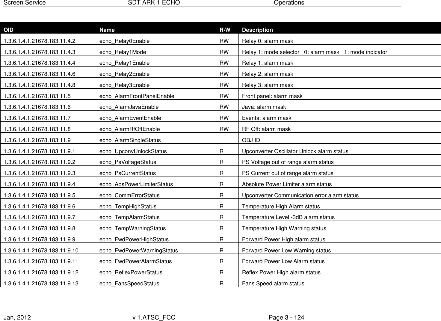
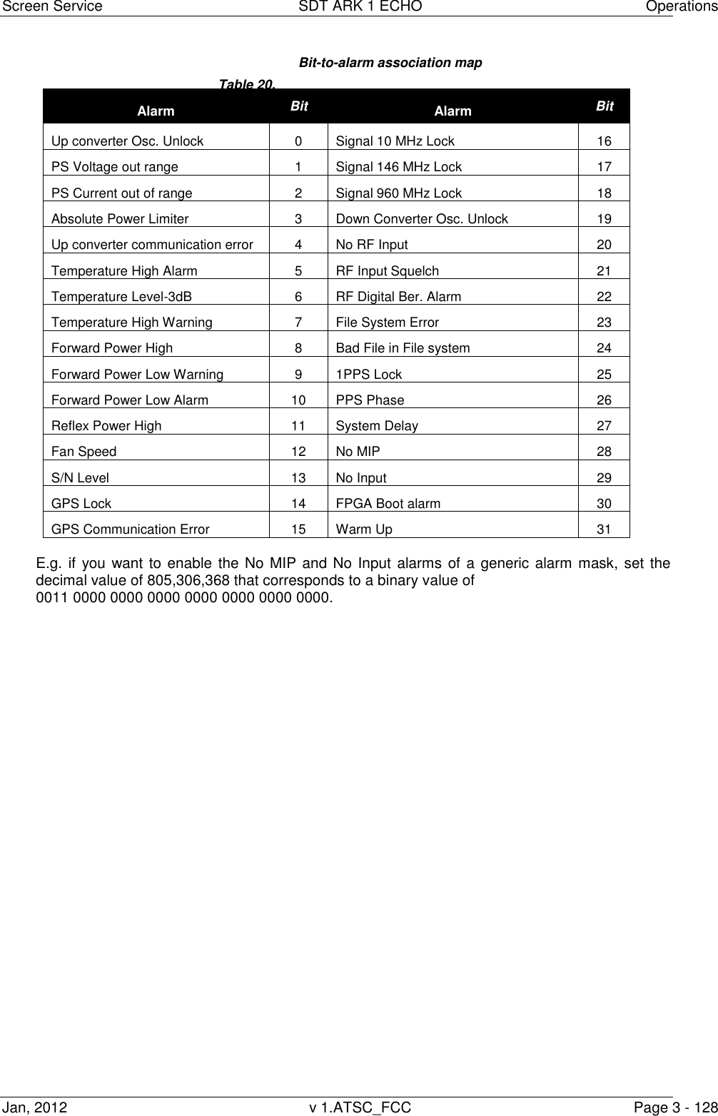
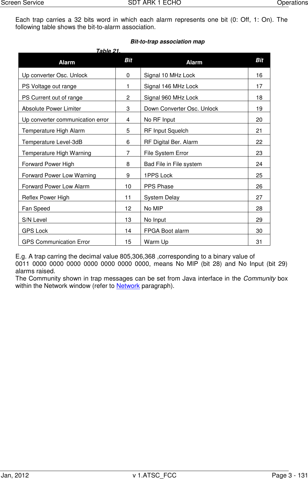
![Screen Service SDT ARK 1 ECHO Operations Jan, 2012 v 1.ATSC_FCC Page 3 - 123 OID Name R\W Description 1.3.6.1.4.1.21678.183.11.1 echo_AlarmThr OBJ ID 1.3.6.1.4.1.21678.183.11.1.1 echo_ThrDemodBer RW Demodulator BER alarm threshold (val * 10^-6) 1.3.6.1.4.1.21678.183.11.1.2 echo_ThrRfSquelchA RW Mode A: Squelch threshold (absolute value) 1.3.6.1.4.1.21678.183.11.1.3 echo_ThrRfSquelchB RW Mode B: Squelch threshold (absolute value) 1.3.6.1.4.1.21678.183.11.1.4 echo_ThrFwdPowerWarning RW Forward power warning threshold (absolute value [dBm x 10] ) 1.3.6.1.4.1.21678.183.11.1.5 echo_ThrFwdPowerAlarm RW Forward power alarm threshold (absolute value [dBm x 10]) 1.3.6.1.4.1.21678.183.11.1.6 echo_ThrTemperatureWarning RW Case temperature warning threshold 1.3.6.1.4.1.21678.183.11.1.7 echo_ThrTemperatureAlarm RW Case temperature alarm threshold 1.3.6.1.4.1.21678.183.11.1.8 echo_ThrSNmodeA RW Mode A: S/N threshold (dBm 10-50) 1.3.6.1.4.1.21678.183.11.1.9 echo_ThrSNmodeB RW Mode B: S/N threshold (dBm 10-50) 1.3.6.1.4.1.21678.183.11.1.10 echo_MipAlarmDelay RW MIP missing alarm delay [val * 100 ms] 1.3.6.1.4.1.21678.183.11.2 echo_AlarmStatus R 32 bits word indicating alarms status (each bit is associated to an alarm) 1.3.6.1.4.1.21678.183.11.3 echo_AlarmTrap OBJ ID 1.3.6.1.4.1.21678.183.11.3.1 echo_Trap0Enable RW Trap 0: alarm mask 1.3.6.1.4.1.21678.183.11.3.2 echo_Trap1Enable RW Trap 1: alarm mask 1.3.6.1.4.1.21678.183.11.3.3 echo_Trap2Enable RW Trap 2: alarm mask 1.3.6.1.4.1.21678.183.11.3.4 echo_Trap3Enable RW Trap 3: alarm mask 1.3.6.1.4.1.21678.183.11.3.5 echo_Trap4Enable RW Trap 4: alarm mask 1.3.6.1.4.1.21678.183.11.3.6 echo_Trap5Enable RW Trap 5: alarm mask 1.3.6.1.4.1.21678.183.11.3.7 echo_Trap6Enable RW Trap 6: alarm mask 1.3.6.1.4.1.21678.183.11.3.8 echo_Trap7Enable RW Trap 7: alarm mask 1.3.6.1.4.1.21678.183.11.4 echo_AlarmRelay OBJ ID 1.3.6.1.4.1.21678.183.11.4.1 echo_Relay0Mode RW Relay 0: mode selector 0: alarm mask 1: mode indicator 2: RF status](https://usermanual.wiki/Screen-Service-Broadcasting-Technologies/STDX-ARK-ECHO/User-Guide-1622747-Page-150.png)