Screen Service Broadcasting Technologies STDX-ARK-ECHO 20 Watt Multimode SDR Repeater w/ Echo Cancellation User Manual ATSC v1 0
Screen Service Broadcasting Technologies SpA 20 Watt Multimode SDR Repeater w/ Echo Cancellation ATSC v1 0
User Manual ATSC v1.0

SDT ARK 1 ECHO
Software Defined
Transposer / Re-Transmitter
Gap Filler / Echo canceller
OPERATION MANUAL
Jan 2012 - Version 1.ATSC_FCC_
© 1997 - 2012. Copyright by:
Screen Service Broadcasting Technologies S.p.A.
Via Giuseppe Di Vittorio, 17
25125 Brescia, Italy
All rights reserved.
All specifications, characteristics and circuit descriptions set forth in this manual are subject to change without notice.

SDT ARK 1 ECHO
Software Defined
Transposer / Re-Transmitter
Gap Filler / Echo canceller
OPERATION MANUAL
Jan 2012 - Version 1.ATSC_FCC
© 1997 - 2012. Copyright by:
Screen Service Broadcasting Technologies S.p.A.
Via Giuseppe Di Vittorio, 17
25125 Brescia, Italy
All rights reserved.
All specifications, characteristics and circuit descriptions set forth in this manual are subject to change without notice.

Screen Service SDT ARK 1 ECHO Contents
Jan, 2012 v 1.ATSC_FCC ii
SDT ARK 1 ECHO
Software Defined
Transposer / Re-Transmitter
Gap Filler / Echo canceller
OPERATION MANUAL
LIST OF CONTENTS
CHAPTER 1: GENERAL INFORMATION
Gives information on safety procedures and good practices to follow using
the equipment.
CHAPTER 2: PURPOSE AND PLANNING
Introduction to the manual, technical specifications, brief functional
description with block diagram.
CHAPTER 3: OPERATIONS
Installation and unpacking instructions, mounting specifications, controls
and connections, first time operating procedures and channel changing
procedures.
CHAPTER 4: TECHNICAL INFORMATION
Provides technical information on all modules including schematic
diagrams and components layouts.
CHAPTER 5: MANUAL CHANGE INFORMATION
Contents of this publication may not be reproduced in any form without the written permission of Screen Service Broadcasting
Technologies S.p.A. No representation or warranty is given and no liability is assumed by Screen Service Broadcasting Technologies
S.p.A. with respect to the accuracy or use of such information, or infringement of patents or other intellectual property rights arising
from such use or otherwise. All trademarks mentioned herein are the property of their respective companies.

Screen Service SDT ARK 1 ECHO General information
Jan, 2012 v 1.ATSC_FCC Page 1 - 1
SDT ARK 1 ECHO
Software Defined
Transposer / Re-Transmitter
Gap Filler / Echo canceller
OPERATION MANUAL
1 GENERAL INFORMATION
CONTENTS
1.1 SAFETY SUGGESTIONS ...................................................................................................................... 2
1.2 GENERAL SAFETY RECOMMENDATIONS ......................................................................................... 3
1.3 GOOD PRACTICES ............................................................................................................................... 3
1.4 PROCEDURE FOR ESTABLISH THE ABSENCE OF VOLTAGE ......................................................... 4
1.4.1 PROCEDURE FOR DETERMINATION OF THE ABSENCE OF VOLTAGE ................................. 4
1.5 FIRST AID IN CASE OF ELECTRICAL SHOCK .................................................................................... 5
1.5.1 EMERGENCY RESUSCITATION TECHNIQUE ............................................................................. 5
1.5.2 TREATMENT FOR BURNS ............................................................................................................ 6
1.5.3 ELECTRIC SAFETY PRECAUTIONS ............................................................................................. 7
1.5.4 COMPONENTS CONTAINING TOXIC MATERIAL HANDLING PRECAUTION ........................... 7
1.5.5 ELECTROSTATIC PRECAUTIONS ................................................................................................ 7
1.6 R&TTE DIRECTIVE 1999/5/EC .............................................................................................................. 8
1.7 WASTE ELECTRICAL AND ELECTONIC EQUIPMENT (WEEE) ......................................................... 9
1.8 RADIO LINK SYSTEM SPECIAL ADVISE: EN 50385 STANDARD ...................................................... 9

Screen Service SDT ARK 1 ECHO General information
Jan, 2012 v 1.ATSC_FCC Page 1 - 2
1.1 SAFETY SUGGESTIONS
Regardless of how well electrical equipment is designed, personnel can be exposed to dangerous
electrical shock when protective covers are removed for maintenance or other activities. Therefore, it is
incumbent on the user to see that all safety regulations are consistently observed and that each individual
assigned to the equipment has a clear understanding of the first aid related to electrical shocks. (see next
pages)
In addition these safety practices must be followed:
Do not attempt to adjust unprotected circuit controls or to dress leads with power on.
Always avoid placing parts of the body in series between ground and circuit points.
To avoid burns, do not touch heavily loaded or overheated components without precautions.
Remember that some semiconductor cases and solid-state circuits carry high voltages.
Do not assume that all danger of electrical shock is removed when the power is off. Charged
capacitors can retain dangerous voltages for a long time after power is turned off. These capacitors
should be discharged trough a suitable resistor before any circuit points are touched.
Don't take chances. Be fully trained. Screen Service Italia equipment should be operated and
maintained by fully qualified personnel.
Do not service alone and do not perform internal adjustments of this unit unless another person
capable of rendering first aid and resuscitation is present.
Some components used in the construction of this equipment contain Beryllium Oxide (BeO). This
substance is harmless as it is, but becomes highly dangerous if it is ground to powder. Special
procedures of disposal must be observed in case of failure of these devices.
NOTE: This section is not intended to contain a complete statement of all safety precautions which
should be observed by personnel in using this electronic equipment or others.
Screen Service shall not be responsible for injury or damage resulted from improper procedures or from
using it by improperly trained or inexperienced personnel.

Screen Service SDT ARK 1 ECHO General information
Jan, 2012 v 1.ATSC_FCC Page 1 - 3
1.2 GENERAL SAFETY RECOMMENDATIONS
When connecting the equipment to the power, please follow these important recommendations:
This product is intended to operate from a power source that will not apply more than 10% of the
voltage specified on the rear panel between the supply conductors or between either supply
conductor and ground. A protective-ground connection by way of the grounding conductor in the
power cord is essential for safe operation.
This equipment is grounded through the grounding conductor of the power cord. To avoid electrical
shock, plug the power cord into a properly wired socket before connecting to the product input or
output terminals.
Upon loss of the protective-ground connection, all accessible conductive parts (including parts that
may appear to be insulating) can render an electric shock.
To avoid fire hazard, use only the fuse of correct type, voltage rating, and current rating. Refer fuse
replacement to qualified service personnel.
To avoid explosion, do not operate this equipment in an explosive atmosphere.
To avoid personal injury, do not remove the product covers or panels. Do not operate the product
without the covers and panels properly installed.
1.3 GOOD PRACTICES
In maintaining the equipment covered in this manual, please keep in mind the following, standard good
practices:
At regular intervals, the condition of the equipment and the correct functioning of protective and
safety devices shall be checked by a skilled person approved by the appropriate authority for this
duty. Functional checks shall be carried out on interlocking systems of doors, mechanical interlocks,
isolating switches, earthing switches, parallel resistances and protective devices against over-
voltages and over-currents. The above checks shall not be carried out after the protective and safety
devices have operated under fault conditions. The safety devices shall not be altered or
disconnected except for replacement, nor shall the safety circuit be modified without specific
approval of the appropriate authority in each case.
When connecting any instrument (wattmeter, spectrum analyzer, etc.) to a high frequency output,
use the appropriate attenuator or dummy load to protect the final amplifiers and the instrument input.
When inserting or removing printed circuit boards (PCBs), cable connectors, or fuses, always turn off
power to the affected portion of the equipment. After power is removed, allow sufficient time for the
power supplies to bleed down before reinserting PCBs.
When troubleshooting, remember that FETs and other metal-oxide semiconductor (MOS) devices
may appear defective because of leakage between traces or component leads on the printed circuit
board. Clean the printed circuit board and recheck the MOS device before assuming it is defective.
When replacing MOS devices, follow standard practices to avoid damage caused by static charges
and soldering.
When removing components from PCBs (particularly ICs), use care to avoid damaging PCB traces.

Screen Service SDT ARK 1 ECHO General information
Jan, 2012 v 1.ATSC_FCC Page 1 - 4
1.4 PROCEDURE FOR ESTABLISH THE ABSENCE OF VOLTAGE
Follow these simple steps for establish the absence of voltage:
Before starting work on the equipment, it shall be isolated from the mains supply. This disconnection
shall always be checked by visual inspection. Further precautions shall be taken to ensure that the
mains supp!y cannot be restored whilst work is being carried out. After the mains supply has been
disconnected, all other lines such as control, interlocking and modulation lines shall be disconnected
if they carry dangerous voltages. Moreover, the antenna or the antenna transmission line shall be
disconnected from the antenna terminal device to prevent the introduction of dangerous voltages
due to antenna pick-up. When disconnection of the antenna or antenna transmission line is not
possible, other suitable precautions shall be taken, for example, earthing, when necessary at several
places, to esablish absence of voltage. These earthing connections shall be very short compared
with the wave-lenght.
Capacitors which are connected to a circuir isolated frcm its supply shall be discharged and have
their terminals permanently short-circuited and the casing earthed during the whole period of the
work.
The electrical charge retained by electrical machinery when stopped may, in certain cases, be
sufficient to cause a severe shock. This shall be taken into account when making connections to an
apparently "dead" machine. Therefore all machinery shall be discharged and earthed using an
adequately insulated lead for this purpose. The discharge operation shall be repeated several times.
Before any maintenance work is carried out on automatic or remote controlled equipment, the
remote swithching circuits shall be made inoperative.
1.4.1 PROCEDURE FOR DETERMINATION OF THE ABSENCE OF VOLTAGE
After the equipment has been isolated according to the standard EN60215, the absence of voltage shall be
determined at the work place. This may be done by the use of voltage indicators, measuring instruments,
glow discharge lamps for indicating radio-frequency voltage or other suitable means.
Screen Service SDT ARK 1 ECHO General information
Jan, 2012 v 1.ATSC_FCC Page 1 - 5
1.5 FIRST AID IN CASE OF ELECTRICAL SHOCK
If someone seems unable to free himself while receiving an electric shock, turn power off before rendering
aid. A muscular spasm or unconsciousness can make a victim unable to free himself from the electrical
power.
If power cannot be turned off immediately, very carefully loop a length of dry non-conducting material (such
as a rope, insulating material, or clothing) around the victim and pull him free of the power. Carefully avoid
touching him or his clothing until free of power.
1.5.1 EMERGENCY RESUSCITATION TECHNIQUE
Step 1
Check the victim for unresponsiveness. If there is no response, immediately call for
medical assistance, and then return to the person.
Step 2
Position the person flat on their back. Kneel by their side and place one hand on the
forehead and the other under the chin. Tilt the head back and lift the chin until teeth
almost touch. Look and listen for breathing.
Step 3
If not breathing normally, pinch the nose and cover the mouth with yours. Give two
full breaths. The person's chest will rise if you are giving enough air.
Step 4
Put the fingertips of your hand on the Adam's apple, slide them into the groove next
to the windpipe. Feel for a pulse. If you can not feel a pulse or are unsure, move on
to the next step.
DO NOT TOUCH VICTIM OR HIS CLOTHING BEFORE
POWER IS DISCONNECTED OR YOU CAN ALSO
BECOME A SHOCK VICTIM

Screen Service SDT ARK 1 ECHO General information
Jan, 2012 v 1.ATSC_FCC Page 1 - 6
Step 5
Position your hands in the center of the chest between the nipples. Place one hand on
top of the other.
Step 6
Push down firmly two inches. Push on chest 15 times.
CONTINUE WITH TWO BREATHS AND 15 PUMPS UNTIL HELP ARRIVES.
1.5.2 TREATMENT FOR BURNS
Continue treat victim for electrical shock.
Check for points of entry and exit of current.
Cover burned surface with a clean dressing.
Remove all clothing from the injured area, but cut around any clothing that adheres to the skin and leave
it in place. Keep the patient covered, except the injured part, since there is a tendency to chill.
Splint all fractures. (Violent muscle contractions caused by the electricity may result in fractures.)
Never permit burned surfaces to be in contact with each other, such as: areas between the fingers or
toes, the ears and the side of the head, the undersurface of the arm and the chest wall, the folds of the
groin, and similar places..
Transport to a medical facility
Screen Service SDT ARK 1 ECHO General information
Jan, 2012 v 1.ATSC_FCC Page 1 - 7
1.5.3 ELECTRIC SAFETY PRECAUTIONS
All the parts making up the equipment have got danger identification tags (with a yellow background) to
highlight the parts dangerous for the operator that has access to the system.
Presence of hazardous energy levels
A hazardous energy level is defined as a stored energy level of 20 J or more, or an
available continuous power level of 240 VA or more, at a potential of 2 V or more.
1.5.4 COMPONENTS CONTAINING TOXIC MATERIAL HANDLING PRECAUTION
Beryllium (BERILLIUM OXIDE) is used in the construction of the some of the components in this equipment.
This material, when in the form of fine dust or vapor and inhaled into the lungs, can cause a respiratory
disease. In its solid form, as used here, it can be handled quite safely although it is prudent to avoid handling
conditions which promote dust formation by surface abrasion.
Because of this hazard, you are advise to be very careful in removing and disposing of these components.
Do not put them in the general industrial or domestic waste or dispatch them by post. They should be
separately and securely packed and clearly identified to show the nature of the hazard and then disposed of
in a safe manner by an authorized toxic waste contractor.
Before removing or replacing any RF COMPONENTS, make sure that all precautions comply with SAFETY
recommendations.
This WARNING tag is used for the RF COMPONENTS.
1.5.5 ELECTROSTATIC PRECAUTIONS
Before removing or replacing any PCB assembly within the equipment, make sure that all precautions
comply with ESD protections (ESD = Electro Static Discharge). Make sure that electrostatic discharge
protections are reset after maintenance and/or measurement operations.
This ATTENTION tag is used for the majority of electronic devices that are sensitive to
electrostatic discharges.
If electronic parts have to be touched during installation or repair, please observe the following precautions.
Operators must be equipped with anti-static protection devices such as:
Elastic wrist band. To be fixed on the operat
Flexible cord. To be connected to the elastic wrist band and the special plug on
the shelf highlighted with the ESD warning label.

Screen Service SDT ARK 1 ECHO General information
Jan, 2012 v 1.ATSC_FCC Page 1 - 8
1.6 R&TTE DIRECTIVE 1999/5/EC
Declaration of Conformity with regards to the R&TTE Directive 1999/5/EC
English:
This equipment is in compliance with the essential requirements and other relevant
provisions of Directive 1999/5/EC
Deutsch:
Dieses Gerät entspricht den grundlegenden Anforderungen und den weiteren
entsprechenden Vorgaben der Richtlinie 1999/5/EU.
Dansk:
Dette udstyr er i overensstemmelse med de væsentlige krav og andre relevante
bestemmelser i Directiv 1999/5/EF.
Español:
Este equipo cumple con los requisitos esenciales asi como con otras disposiciones de la
Directiva 1999/5/EC.
Français:
Cet appareil est conforme aux exigences essentielles et aux autres dispositions pertinentes
de la Directive 1999/5/EC.
Íslenska:
Þessi búnaður samrýmist lögboðnum kröfum og öðrum ákvæðum tilskipunar 1999/5/ESB.
Italiano:
Questo apparato é conforme ai requisiti essenziali ed agli altri principi sanciti dalla Direttiva
1999/5/EC.
Nederlands:
Deze apparatuur voldoet aan de belangrijkste eisen en andere voorzieningen van richtlijn
1999/5/EC.
Norsk:
Dette utstyret er i samsvar med de grunnleggende krav og andre relevante bestemmelser i
EU-directiv 1999/5/EC.
Português:
Este equipamento satisfaz os requisitos essenciais e outras provisões da Directiva
1999/5/EC.
Suomalainen:
Tämä laite täyttää direktiivin 1999/5/EY oleelliset vaatimukset ja on siinä asetettujen
muidenkin ehtojen mukainen.
Svenska:
Denna utrustning är i överensstämmelse med de väsentliga kraven och andra relevanta
bestämmelser i Direktiv 1999/5/EC.
The Declaration of Conformity related to this product can be found at the following URL: www.screen.it/rtte
The following CE mark is affixed to the equipment:
RADIO LINKS:
0470
TV BROADCASTING EQUIPMENTS:
0648
The identification number of the Notified Body who certified the product might change.
This equipment is intended to be used in all EU and EFTA countries.
The use of this equipment may be restricted to certain frequencies and requires a license for
operation. For more details, contact your customer service representative.

Screen Service SDT ARK 1 ECHO General information
Jan, 2012 v 1.ATSC_FCC Page 1 - 9
1.7 WASTE ELECTRICAL AND ELECTONIC EQUIPMENT (WEEE)
The purpose of the DIRECTIVE 2002/96/EC OF THE EUROPEAN
PARLIAMENT AND OF THE COUNCIL of 27 January 2003 on waste electrical
and electronic equipment (WEEE) is, as first priority, the prevention of waste
electrical and electronic equipment and, in addition, the reuse, recycling and
other forms of recovery of such wastes so as to reduce the disposal of waste.
To do this, remember to collect separately all the
electronic material.
1.8 RADIO LINK SYSTEM SPECIAL ADVISE: EN 50385 STANDARD
The responsible of the installation and (or) the use of the RADIOLINK SYSTEM composed of:
EQUIPMENT(s)
CONNECTION(s)
ANTENNA(s)
Shall certify under its own responsibility the conformity as per EN 50385 standard:
EN 50385:2002 - Product standard to demonstrate the compliance of radio base stations and fixed terminal
stations for wireless telecommunication systems with the basic restrictions or the reference levels related to
human exposure to radio frequency electromagnetic fields (110 MHz - 40 GHz) - General public.

Screen Service SDT ARK 1 ECHO Purpose and planning
Jan, 2012 v 1.ATSC_FCC Page 2 - 1
SDT ARK 1 ECHO
Software Defined
Transposer / Re-Transmitter
Gap Filler / Echo canceller
OPERATION MANUAL
2 PURPOSE AND PLANNING
CONTENTS
2.1 GENERALITY ......................................................................................................................................... 3
2.2 INTRODUCTION .................................................................................................................................... 3
2.2.1 ANALOG/DIGITAL TELEVISION HETERODYNE TRANSPOSER ................................................ 3
2.2.2 DIGITAL TELEVISION HETERODYNE TRANSPOSER WITH ECHO CANCELLER .................... 4
2.2.3 RE-BROADCASTING ATSC MODULATOR ................................................................................... 4
2.2.4 FUNCTIONAL BLOCK DIAGRAMS ................................................................................................ 5
2.3 PURPOSE .............................................................................................................................................. 8
2.4 COMPOSITION ...................................................................................................................................... 8
2.4.1 FRONT AND REAR PANEL FUNCTIONS LIST ............................................................................. 9
2.5 TECHNICAL PERFORMANCE ............................................................................................................ 11
2.5.1 GENERAL ...................................................................................................................................... 11
2.5.2 MECHANICAL AND ENVIRONMENTAL ...................................................................................... 11
2.5.3 INPUT PARAMETERS .................................................................................................................. 11
2.5.3.1 RF ........................................................................................................................................... 11
2.5.3.2 ASI 1, 2, 3, 4 ........................................................................................................................... 11
2.5.3.3 GPS ........................................................................................................................................ 12
2.5.3.4 10 MHz ................................................................................................................................... 12
2.5.3.5 1 PPS ..................................................................................................................................... 12
2.5.3.6 OPTOCOUPLERS (4) ............................................................................................................ 12
2.5.4 OUTPUT PARAMETERS .............................................................................................................. 12
2.5.4.1 RF GENERAL ........................................................................................................................ 12
2.5.4.2 RF ATSC MODE .................................................................................................................... 12
2.5.4.3 ASI OUT HP ........................................................................................................................... 12
2.5.4.4 ASI OUT LP ............................................................................................................................ 12
2.5.4.5 RELAYS ................................................................................................................................. 13
2.5.5 DIGITAL MODULATION ................................................................................................................ 13

Screen Service SDT ARK 1 ECHO Purpose and planning
Jan, 2012 v 1.ATSC_FCC Page 2 - 2
2.5.6 MANAGEMENT ............................................................................................................................. 13
2.5.6.1 GIGABIT ETHERNET ............................................................................................................ 13
2.5.6.2 REAR SUB-D 25P CONNECTOR ......................................................................................... 14
2.6 FUNCTIONAL DESCRIPTION ............................................................................................................. 15
2.6.1 GENERAL ...................................................................................................................................... 15
2.6.2 RF AMPLIFICATION ..................................................................................................................... 15

Screen Service SDT ARK 1 ECHO Purpose and planning
Jan, 2012 v 1.ATSC_FCC Page 2 - 3
2.1 GENERALITY
Propagation is a critical issue in ATSC / Mobile TV broadcasting.
In this contest, the use of repeaters for digital TV broadcasting becomes a key issue for commercial
terrestrial distribution of digital TV.
In addition, 8VSB signal characteristics avert well known adjacent channel interference problems of
analogue TV broadcasting. This leads to the SFN network planning: a single frequency is used all over the
coverage territory, increasing spectrum efficiency.
Therefore, in digital TV SFN netwotrks iso-frequency repeaters are needed. An On-channel repeater is,
basically, a radiofrequency repeater that receiver and transmits using the same frequency.
Traditional On-channel repeater use is limited by a hard design constraint: coupling between transmitter and
receiver antenna limits the allowed maximum gain for the on-channel repeater, leading to a reduction of the
coverage area: a traditional on-channel repeater installation is only possible if hard isolation conditions are
complied.
A on-channel repater, with coupling echo cancellation system, allows operations at higher power levels
under normal tower isolation conditions.
2.2 INTRODUCTION
SDT ARK-1 ECHO is a Multi-standard Television Transposer. Based on Software Defined technology, SDTX
ECHO allows the definition of different operative modes on the same hardware platform.
At the state of the art SDT ARK-1 ECHO has the following possible working modes:
Analog Television Heterodyne Transposer;
Digital Television Heterodyne Transposer;
Digital Television Heterodyne Transposer with echo canceller;
Re-broadcasting ATSC Modulator.
Analog and Digital Television Heterodyne Transposers receive and re-transmit Analog or Digital TV signals
allowing the software setting of input and output channels.
Re-broadcasting ATSC Modulator receives and de-modulates ATSC signals and re-modulates them.
Auxiliary inputs and outputs allow to import and export TS contents on ASI and GBE interfaces.
The single software controller allows the switching between working modes and different settings for each
operative mode using the same platform.
A brief description of the main features and potentialities of each operative mode follows.
2.2.1 ANALOG/DIGITAL TELEVISION HETERODYNE TRANSPOSER
Heterodyne Transposer with Digital Filtering at Intermediate Frequency for Analog and Digital Television
standards.
Capable of:
Agile UHF input Down-converter (from 470 MHz up to 862 MHz)
Agile UHF output Up-converter (from 470 MHz up to 862 MHz)
Input Analog/Digital signal level monitoring with quality measurement for ATSC
Digital Filtering at Intermediate Frequency
Echo canceller for Digital signal
AM/PM Software Pre-correction power and frequency calibrated for Digital and Analog signal

Screen Service SDT ARK 1 ECHO Purpose and planning
Jan, 2012 v 1.ATSC_FCC Page 2 - 4
2.2.2 DIGITAL TELEVISION HETERODYNE TRANSPOSER WITH ECHO CANCELLER
Heterodyne Transposer with Digital Filtering at Intermediate Frequency for Analog and Digital Television
standards.
Capable of:
Agile UHF input Down-converter (from 470 MHz up to 862 MHz).
Agile UHF output Up-converter (from 470 MHz up to 862 MHz).
Input Analog/Digital signal level monitoring with quality measurement for ATSC
Digital Filtering at Intermediate Frequency.
Echo canceller for Digital signal.
AM/PM pre-correction calibrated on channel and power ranges for Digital and Analog signal
with manual modeling of the curves on Java GUI.
2.2.3 RE-BROADCASTING ATSC MODULATOR
ATSC Modulator with de-modulator for Digital Television standard.
Capable of:
Agile UHF input Down-converter (channels 21 to 69)
Agile UHF output Up-converter (channels 21 to 69)
Input RF signal level monitoring with quality measurement
Auxiliary Transport Stream inputs on ASI or Gigabit Ethernet
Modulus/Group Delay Software Pre-correction
AM/PM Software Pre-correction
Screen Service SDT ARK 1 ECHO Purpose and planning
Jan, 2012 v 1.ATSC_FCC Page 2 - 5
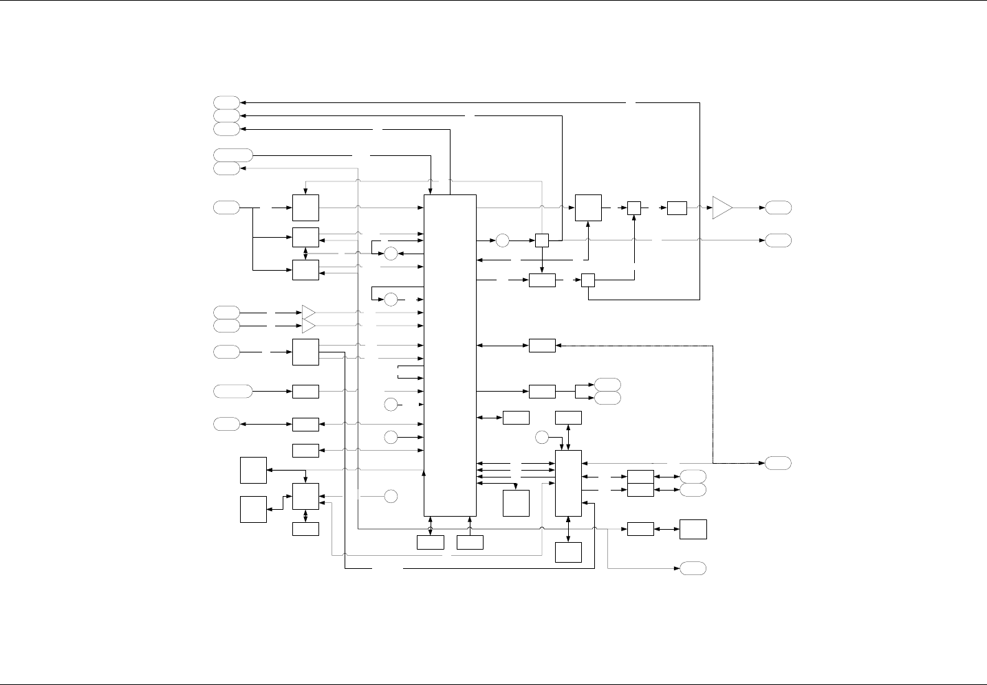
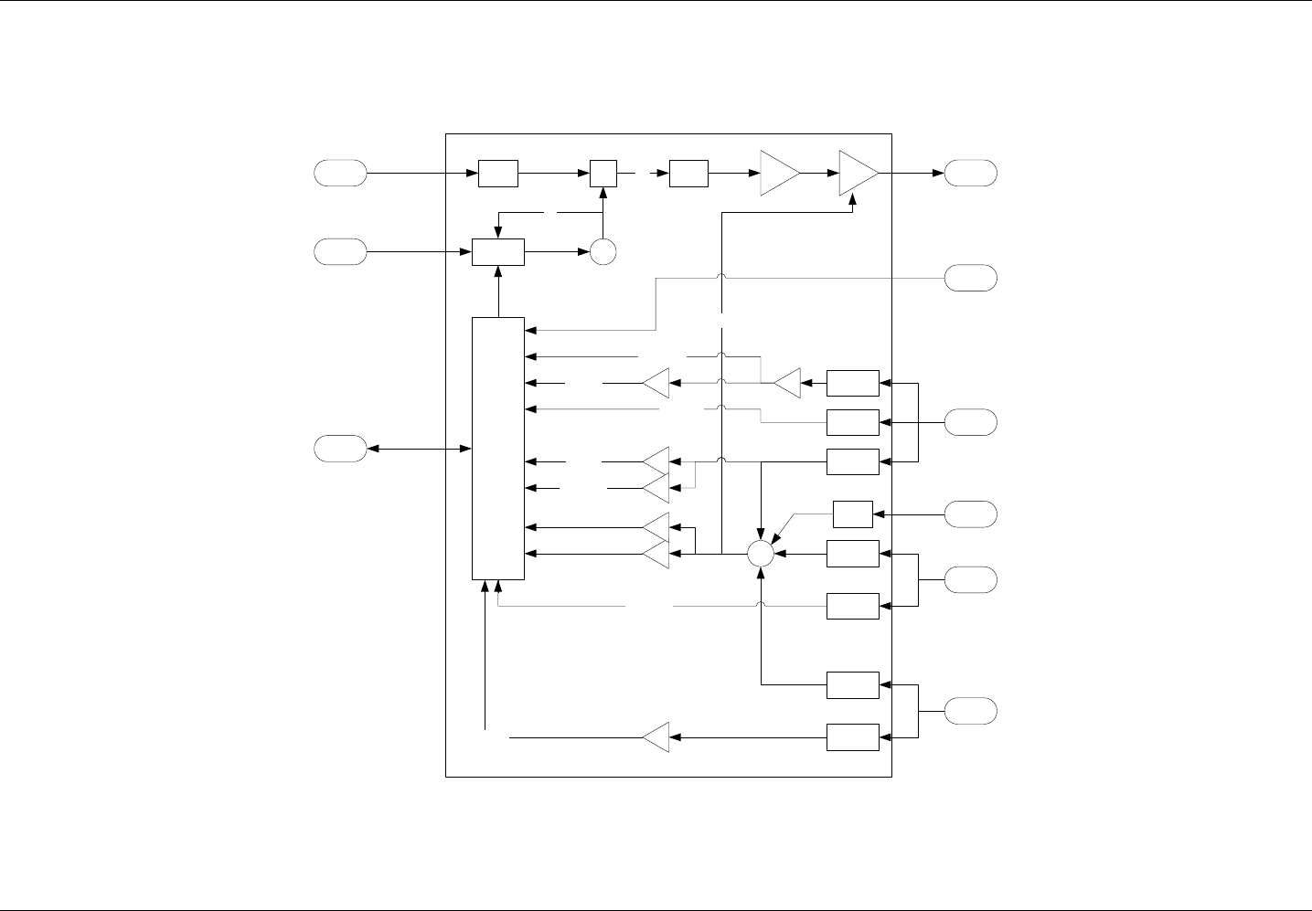
2.2.4 FUNCTIONAL BLOCK DIAGRAMS
Figure 1 Echo board block diagram
4xASI/SDI
FPGA
12
5
FLASH
ARM
DAC
ad9772
GBTH
2xDDR
ASI/
SDI
ADC
GBTH
In IF 36
14
6
STV
STV
IF36
27
27
Krypt
I2C
DSP
JTAG
JTAG
JTAG
11
.0
6
24.576
SDRAM
2xASI ASI HP
ASI LP
ADF Z
Z
146
960
146
Mix
36 996 SAW
MGA
960
146
146
960
146
TS HP
TS_LP
120
10
boot
add
data
ADF
10ext
1PPS
C C
ext
ext
10M
10M
1PPs
RocketI/O
54 RefCk
960
Ser1
SPI CK+MEM
+MEM
TS SAT
I2C
TS Sat
GPSGPS ant 10M
1PPs
Ser2 NMEA
54
DisplaySer0
Rs232 FabioSer0
Rs485
I2C ext OPTO
Relays
FLASH
Display
FAN
SPI
Down
Conv.
I2C
Sat RX o Down converter alternativi
27
IF_Out
146M
Ser
24
.6
Screen Service SDT ARK 1 ECHO Purpose and planning
Jan, 2012 v 1.ATSC_FCC Page 2 - 6
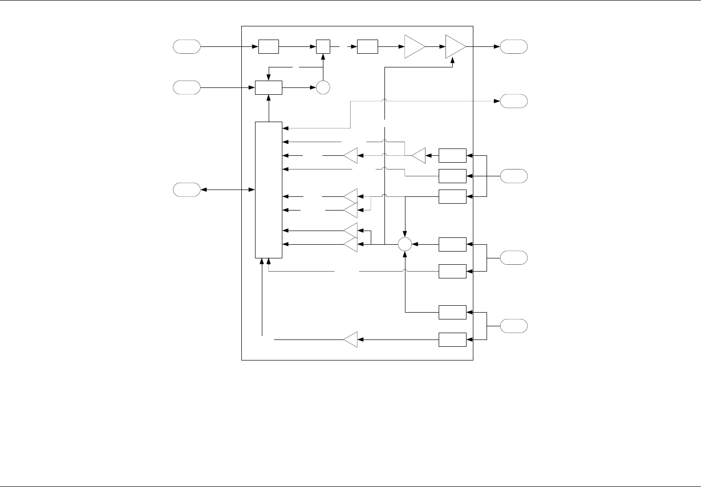
Figure 2 Echo down-converter block diagram
SAW Mix Flt
MGA
ADL
ADF vc
o
Lo
Ch RF Out
ARM
ADUC
Reflect
Forw.
Drive
Detect
Detect
Detect
Detect
Detect
Detect
Detect
+
FeedBack
Fw Out
RMS Fw
RMS Ref
A
A
Peak FW
AAA A
Ph Drv
RMS Drv
A
Peak Drv
Alim
IF_Out
146M
Ser
Screen Service SDT ARK 1 ECHO Purpose and planning
Jan, 2012 v 1.ATSC_FCC Page 2 - 7
Figure 3 Echo 2 up-converter block diagram
SAW Mix Flt
MGA
ADL
ADF vc
o
Lo
Ch RF Out
ARM
ADUC
Reflect
Forw.
Drive
Detect
Detect
Detect
Detect
Detect
Detect
Detect
+
FeedBack
Fw Out
RMS Fw
RMS Ref
A
A
Peak FW
AAA A
Ph Drv
RMS Drv
A
Peak Drv
Alim
IF_Out
146M
Ser
PWMRC
Screen Service SDT ARK 1 ECHO Purpose and planning
Jan, 2012 v 1.ATSC_FCC Page 2 - 8
2.3 PURPOSE
This manual contains information and reference documentation on installation, operation and maintenance of
the SDT ARK 1 equipment.
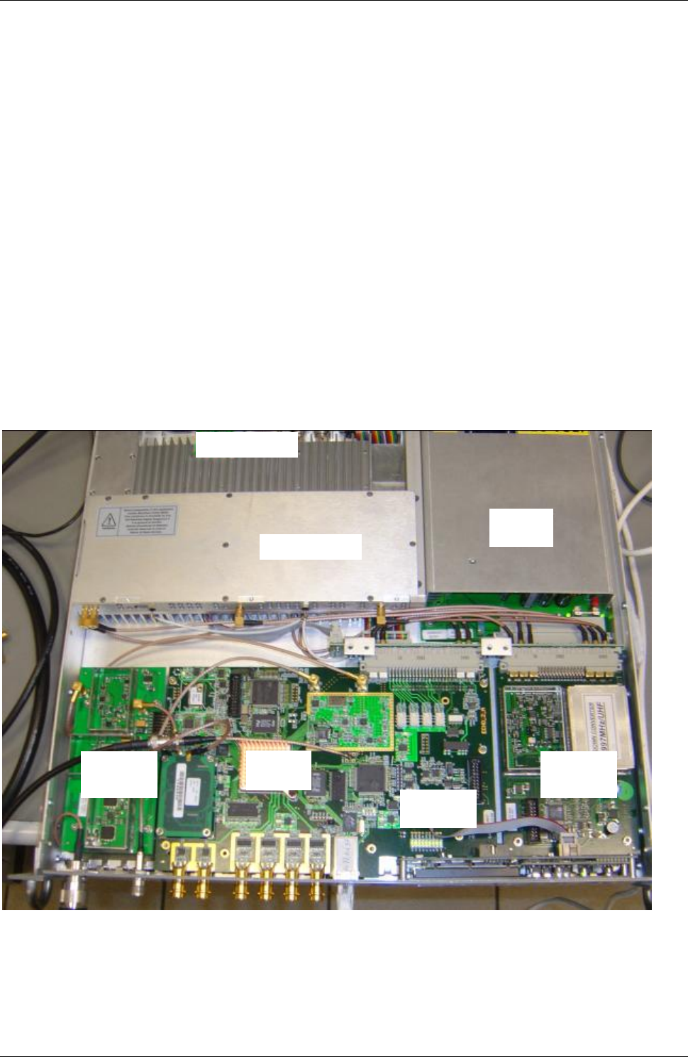
2.4 COMPOSITION
The equipment is composed of the following functional blocks:
1st AC/DC POWER SUPPLY
2nd IF DIGITAL
3rd RF AMPLIFIER
4th COOLING SYSTEM
5TH AGILE DOWN CONVERTER
6TH AGILE UP CONVERTER
7TH DC/DC CONVERTER
AC/DC
POWER
SUPPLY
RF AMPLIFIER
IF
DIGITAL
COOLING SYSTEM
AGILE
DOWN
CONVERTER
AGILE
UP
CONVERTER
DC/DC
CONVERTER
Screen Service SDT ARK 1 ECHO Purpose and planning
Jan, 2012 v 1.ATSC_FCC Page 2 - 9
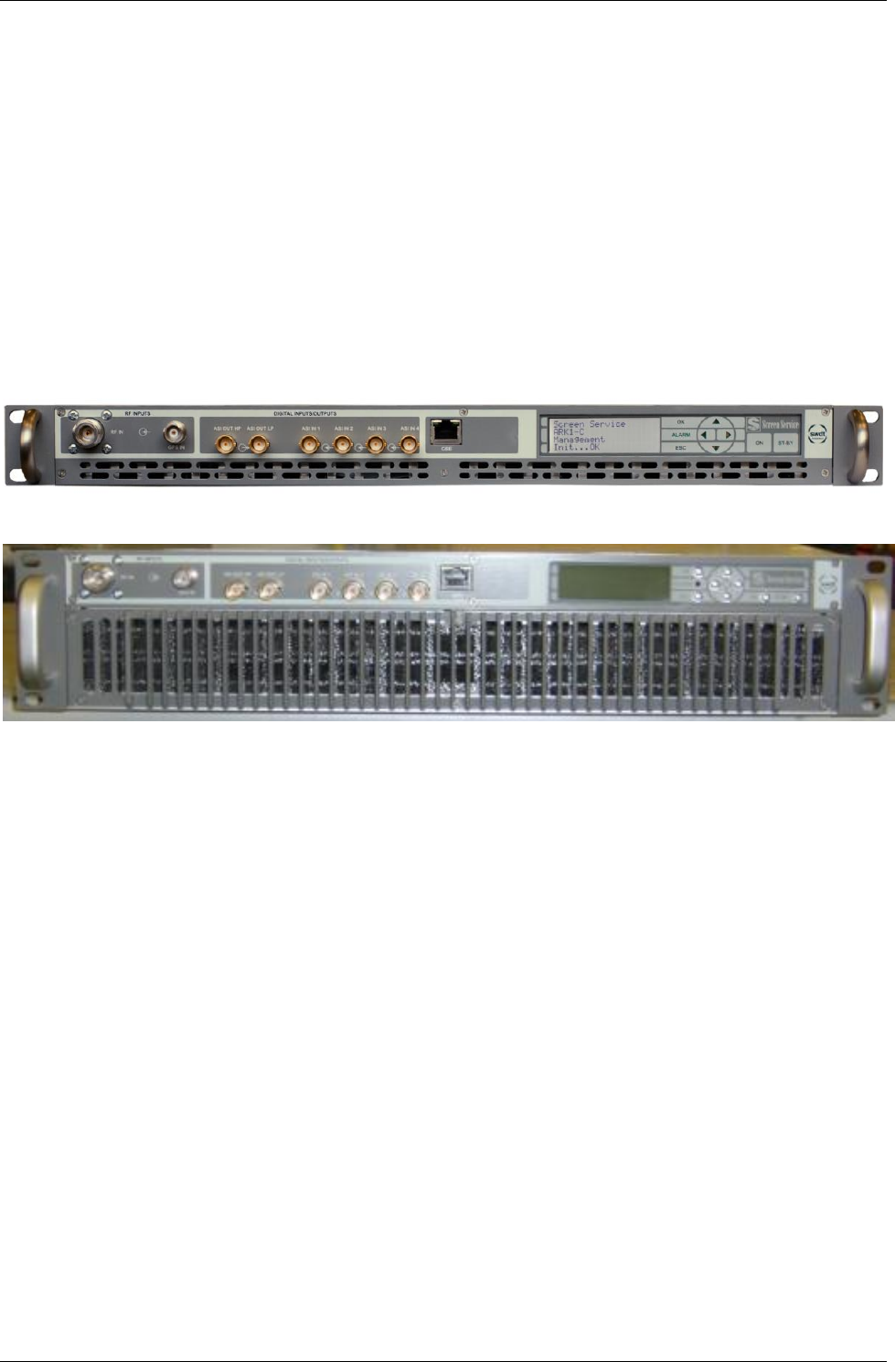
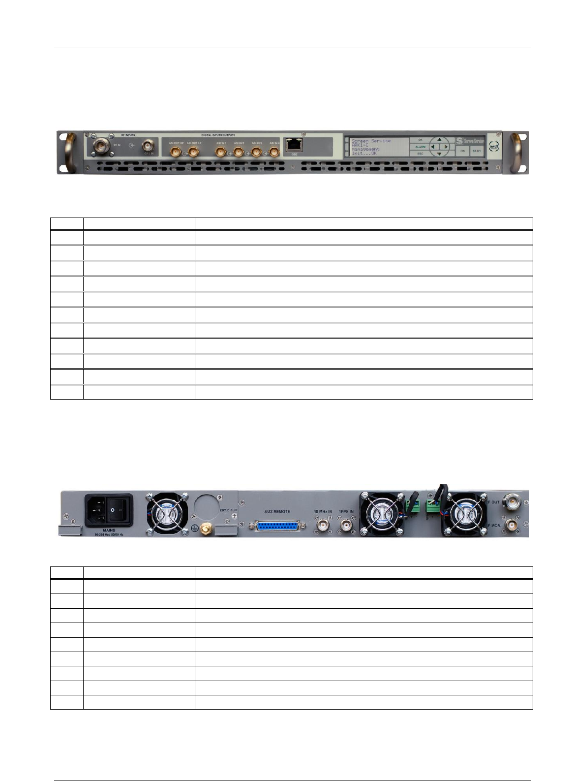
2.4.1 FRONT AND REAR PANEL FUNCTIONS LIST
On the front panel are located the following functions/connectors (from left to right)
1. RF INPUT
2. GPS INPUT
3. ASI OUTPUT HP
4. ASI OUTPUT LP
5. ASI INPUT 1
6. ASI INPUT 2
7. ASI INPUT 3
8. ASI INPUT 4
9. GBE
10. DISPLAY & NAVIGATION
1 2 3 4 5 6 7 8 9 10
1 2 3 4 5 6 7 8 9 10
Screen Service SDT ARK 1 ECHO Purpose and planning
Jan, 2012 v 1.ATSC_FCC Page 2 - 10
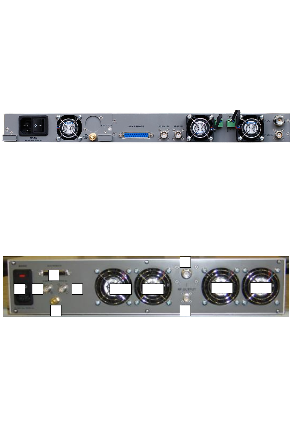
On the rear panel are located the following functions/connectors (from left to right)
1. AC MAIN INPUT & ON/OFF SWITCH
2. AC/DC FAN
3. GROUND REFERENCE
4. AUX REMOTE
5. 10 MHz INPUT
6. 1 PPS INPUT
7. FANs EQUIPMENT COOLING (a & b)
8. RF OUTPUT
9. RF MONITOR
1 2 3 4 5 6 7a 7b 8
9
10. AC MAIN INPUT & ON/OFF SWITCH
11. FANs
12. GROUND REFERENCE
13. AUX REMOTE
14. 10 MHz INPUT
15. 1 PPS INPUT
16. RF OUTPUT
17. RF MONITOR
2
1
1
2 A
3
2
1
1
4
2
1
1
5
2
1
1
6
2
1
1
8
2
1
1
9
2
1
1
2 B
2 C
2 D

Screen Service SDT ARK 1 ECHO Purpose and planning
Jan, 2012 v 1.ATSC_FCC Page 2 - 11
2.5 TECHNICAL PERFORMANCE
2.5.1 GENERAL
Available standards ATSC
Operating frequency range VHF Band I: 45 - 90 MHz
VHF Band III: 174 - 260 MHz
UHF Band IV & V: 470 - 860 MHz
IF Frequency 36 MHz +/- 4
IF Bandwidth 6 -7- 8 MHz (TBS)
Time delay 7 us typ.
ECHO Delay correction capability 20 us max
(Equipment time delay NOT included)
Correction speed 40 mSec (echoes from +10 to -20 dB)
2 Sec (echoes less than -20 dB)
Cooling Forced Air
Main supply 230 V AC
MAX Power consumption 750 VA (SDT 201 UB - ARK 1)
250 VA (SDT 500 UB - ARK 1)
200 VA (SDT 200 UB - ARK 1)
150 VA (SDT 100 UB - ARK 1)
2.5.2 MECHANICAL AND ENVIRONMENTAL
Dimensions 483 mm (W) x 400 mm (D) x 45/90 mm (H)
Weight 10/18 kg approx.
Operating temperature from 0° C to + 45° C
Storage temperature from -10° C to +60° C
Maximum relative humidity 90%, non condensing
2.5.3 INPUT PARAMETERS
2.5.3.1 RF
Input connector N female
Input Signal 8VSB_ATSC_RF
Input Level -45 dBm ± 20 dB
Impedance 50 Ω
2.5.3.2 ASI 1, 2, 3, 4
Input Signal MPEG-2 Transport Stream, ASI format
Input Level 800 mV (±10%)
Data rate 270 MB/s
Data rate error ±3 ppm
Input connector BNC
Input impedance 75 Ω

Screen Service SDT ARK 1 ECHO Purpose and planning
Jan, 2012 v 1.ATSC_FCC Page 2 - 12
2.5.3.3 GPS
Input connector TNC female
Antenna power supply from transmitter, 5V DC
Sensitivity -185dBW
2.5.3.4 10 MHz
Input connector BNC female
Input Impedance 50 Ohm
Level 2 Vpp
2.5.3.5 1 PPS
Input connector BNC female
Input Impedance 50 Ohm
Level TTL
Pulse width 100us
2.5.3.6 OPTOCOUPLERS (4)
Input connector SUB-D 25p Female
Max current -5 mA
2.5.4 OUTPUT PARAMETERS
2.5.4.1 RF GENERAL
RF OUTPUT Connector N Female
Impedance 50 Ω
RF monitor connector BNC
Impedance 50 Ω
2.5.4.2 RF ATSC MODE
Nominal output power SDT 500 UB - ARK 1 20 W RMS
Nominal output power SDT 200 UB - ARK 1 8 W RMS
In-Band Flatness ± 0.5 dB
Shoulders at F0 ± 4.3 MHz ≤ -36 dB
With digital pre-correction inserted
Spurious emission (with output filter) < -60 dBc
Harmonic emission (with output filter) < -60 dBc
2.5.4.3 ASI OUT HP
Output Signal MPEG-2 Transport Stream, ASI format
Output Level 800 mV (±10%)
Data rate 270 MB/s
Data rate error ±3 ppm
Input connector BNC
Input impedance 75 Ω
2.5.4.4 ASI OUT LP
Output Signal MPEG-2 Transport Stream, ASI format
Output Level 800 mV (±10%)
Data rate 270 MB/s
Data rate error ±3 ppm
Input connector BNC
Input impedance 75 Ω

Screen Service SDT ARK 1 ECHO Purpose and planning
Jan, 2012 v 1.ATSC_FCC Page 2 - 13
2.5.4.5 RELAYS
N° outputs
4
Connectors
SUB-D 25p Female
Max voltage
125VAC / 60VDC @ 0,3A
30VDC @ 1A
Modes
(TBD)
Relay 0:
o Alarm mask:
Off: no alarms;
On: one or more alarm conditions.
o Mode:
Off: Mode A;
On: Mode B.
Relay 1:
o Alarm mask:
Off: no alarms;
On: one or more alarm conditions.
o Mode:
Off: Mode A;
On: Mode B.
Relay 2:
o Alarm mask:
Off: no alarms;
On: one or more alarm conditions.
Relay 3:
o Alarm mask:
Off: no alarms;
On: one or more alarm conditions.
2.5.5 DIGITAL MODULATION
Modulation Modes 8VSB
Inputs 2 ASI + 2 SSI
Input Data Rate up to 19.39 Mbps
Channel Bandwidth 6 MHz
Symbol Rate 10.762 MSymbol/sec
Bandwidth Efficiency 3 Bits/symbol
PCR Restamping and Del. Null Packet Included
Frequency Step 1 Hz
Test Signal PRBS, CW
GPS Receiver Integrated
Adaptive Digital Precorrector Integrated
2.5.6 MANAGEMENT
2.5.6.1 GIGABIT ETHERNET
Connector RJ45
Standard supported IEEE 802.3

Screen Service SDT ARK 1 ECHO Purpose and planning
Jan, 2012 v 1.ATSC_FCC Page 2 - 14
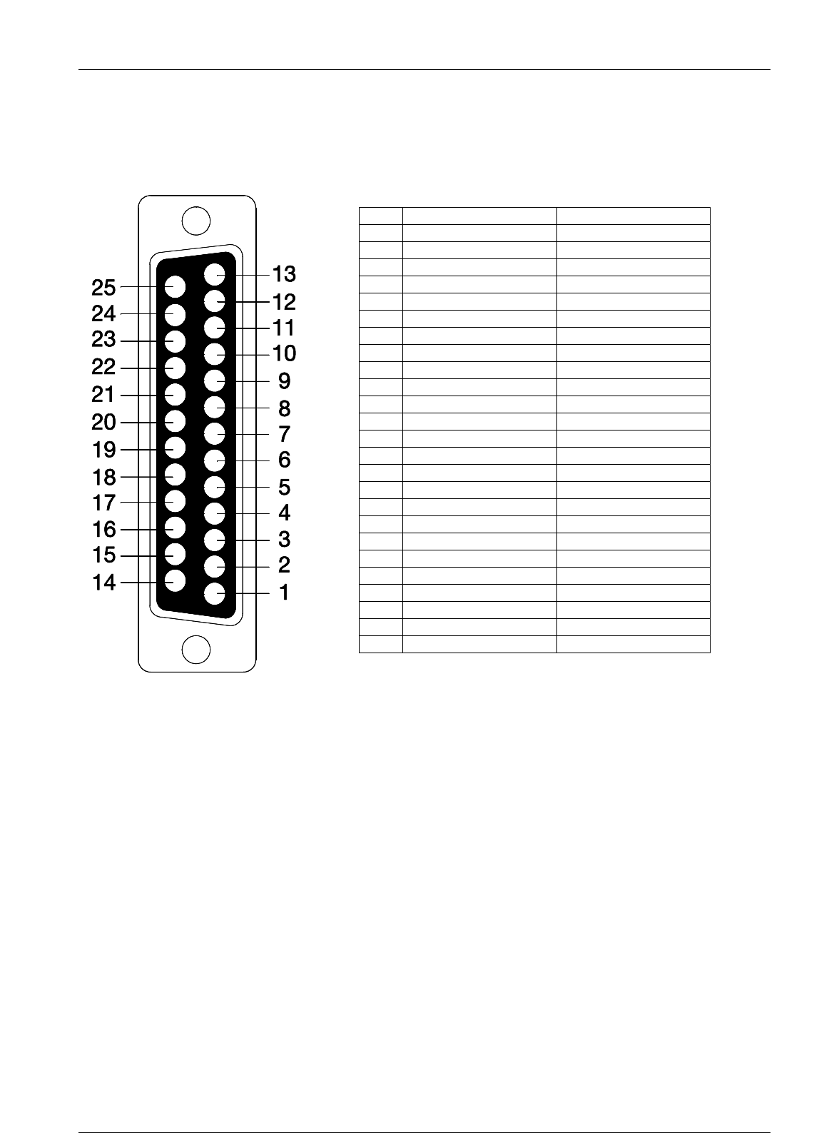
2.5.6.2 REAR SUB-D 25P CONNECTOR
N° connectors
1
Connector
SUB-D 25p Female
Pinout
1
N.C.
2
IN_OPTO_1
3
IN_OPTO_2
4
IN_OPTO_3
5
OPTO_GND
6
N.C.
7
N.C.
8
N.C.
9
RS232 Tx
10
RS232 Rx
11
N.C.
12
IN_OPTO_0
13
N.C.
14
N.C.
15
N.C.
16
FWD_OUT
17
RL_COM0
18
RL0
19
RL_COM1
20
RL1
21
RL_COM2
22
RL2
23
RL_COM3
24
RL3
25
RS232 GND

Screen Service SDT ARK 1 ECHO Purpose and planning
Jan, 2012 v 1.ATSC_FCC Page 2 - 15
2.6 FUNCTIONAL DESCRIPTION
2.6.1 GENERAL
The ARK 1 receives on its inputs An RF signal or four MPEG-2 Transport Stream in serial ASI format.
The RF input signal is converted into a standard 36 MHz IF frequency by a fully agile down converter.
This signal is digitally filtered, elaborated, precorrected and then presented at 997 MHz to the channel
converter.
The channel converter provides to generate the final frequency in a fully agile mode.
The LO with a very low phase noise is locked to the 146 MHz high stability reference.
Reference signal coming from GPS board allow precision offset
The switching power supply module generates the following voltages to feed the different circuits: +32 V,
+ 24V.
2.6.2 RF AMPLIFICATION
The signal coming from the agile up converter goes to the RF amplifier section. The RF amplification is done
by class A and AB stages.
Out of the final stage, the RF signal passes through a directional coupler. The directional coupler detects
samples of direct and reflected power and passes this information to the check function

Screen Service SDT ARK 1 ECHO Operations
Jan, 2012 v 1.ATSC_FCC Page 3 - 1
SDT ARK 1 ECHO
Software Defined
Transposer / Re-Transmitter
Gap Filler / Echo canceller
OPERATION MANUAL
3 OPERATIONS
CONTENTS
3.1 INSTALLATION ...................................................................................................................................... 3
3.1.1 INSTALLATION PROCEDURE CHECK OFF ..................................................................................... 3
3.1.2 SITE SELECTION ............................................................................................................................... 3
3.1.2.1 MOUNTING SPECIFICATIONS .................................................................................................. 3
3.1.3 UNPACKING ....................................................................................................................................... 3
3.1.4 EQUIPMENT MOUNTING .................................................................................................................. 4
3.1.5 FRONT PANEL ................................................................................................................................... 5
3.1.5.1 REAR PANEL .............................................................................................................................. 5
3.1.5.2 REAR PANEL CONNECTORS.................................................................................................... 6
3.1.6 MULTIMETER ..................................................................................................................................... 7
3.1.7 LOCAL INTERRFACE MENU TREE .................................................................................................. 8
3.1.8 BOOT AND WELCOME MESSAGE ................................................................................................. 11
3.2 IDLE MENU ....................................................................................................................................... 12
3.2.1 MAIN MENU ...................................................................................................................................... 13
3.3 LCD alarms ....................................................................................................................................... 14
3.4 JAVA REMOTE GRAPHIC USER INTERFACE .................................................................................. 16
3.4.1 JAVA INTERFACE OVERVIEW ....................................................................................................... 16
3.4.1.1 General ...................................................................................................................................... 18
3.4.1.2 Input ........................................................................................................................................... 19
3.4.1.3 TUNER ....................................................................................................................................... 24
3.4.2 Modes management .................................................................................................................. 24
3.4.3 Modes switching rules ................................................................................................................ 29
3.4.4 Tuner management .................................................................................................................... 30
3.4.5 MODULATION .................................................................................................................................. 35
3.4.6 Modulator management ............................................................................................................. 35
3.4.7 Network Synchronization parameters setting ............................................................................ 38
3.4.8 Modulation parameters .............................................................................................................. 39
3.4.9 ATSC parameters ...................................................................................................................... 43
3.4.10 MIP functions ............................................................................................................................. 45
3.5 PRE-CORRECTION TOOL ............................................................................................................... 51
3.5.1 Module&Phase ........................................................................................................................... 51
3.5.2 AM/PM ....................................................................................................................................... 52

Screen Service SDT ARK 1 ECHO Operations
Jan, 2012 v 1.ATSC_FCC Page 3 - 2
3.5.3 Connection to port 5000 ............................................................................................................. 55
3.6 Channel filter & complex filter ........................................................................................................... 56
3.6.1 OUTPUT ............................................................................................................................................ 62
3.7 NETWORK ........................................................................................................................................ 70
3.8 GPS ................................................................................................................................................... 75
3.9 ALARMS ............................................................................................................................................ 77
3.10 EVENTS ............................................................................................................................................ 84
3.10.1 Task Error Event ........................................................................................................................ 88
3.10.2 Init System Event ....................................................................................................................... 88
3.11 System menu .................................................................................................................................... 92
3.11.1 File menu ................................................................................................................................... 92
3.11.2 View menu ................................................................................................................................. 93
3.11.2.1 Option sub-menu ................................................................................................................ 93
3.11.2.2 Time .................................................................................................................................... 93
3.11.2.3 Alerts ................................................................................................................................... 94
3.11.3 Help menu .................................................................................................................................. 95
3.11.3.1 About................................................................................................................................... 96
3.11.3.2 Info ...................................................................................................................................... 96
3.12 Download Software Standalone ........................................................................................................ 98
3.13 SNMP – Simple Network Management Protocol .................................................................................. 99
3.14 SNMP Protocol Preferences ........................................................................................................... 100
3.15 Communities ................................................................................................................................... 101
3.16 Monitoring ........................................................................................................................................ 102
3.17 OID .................................................................................................................................................. 103
3.17.1 SNMP tree structure ................................................................................................................ 103
3.18 Configuring alarms masks ............................................................................................................... 127
3.19 Traps ............................................................................................................................................... 129
3.19.1 Configuring traps ...................................................................................................................... 129
3.20 AUTOMATIC FREQUENCY CONTROL ............................................................................................ 132
3.21 APPLICATION NOTE 1 ...................................................................................................................... 136
3.21.1 How to update ................................................................................................................................. 136
3.22 Java Virtual Machine .......................................................................................................................... 140
3.23 ETHERNET CONNECTION ............................................................................................................... 141
3.23.1 Configuration ................................................................................................................................... 141
3.23.2 Java(TM) Platform ........................................................................................................................... 141
3.23.3 Download ........................................................................................................................................ 141
3.23.4 Java Control Panel .......................................................................................................................... 141
3.24 SUPPORTED WEB BROWSERS ...................................................................................................... 143

Screen Service SDT ARK 1 ECHO Operations
Jan, 2012 v 1.ATSC_FCC Page 3 - 3
3.1 INSTALLATION
3.1.1 INSTALLATION PROCEDURE CHECK OFF
Some procedures in this section contain steps preceded by a check box. Fill out or initial each step as it is
completed.
3.1.2 SITE SELECTION
Use the following specifications to establish criteria for site selection and equipment installation.
3.1.2.1 MOUNTING SPECIFICATIONS
Mount.
A floor-standing, open rack or permanent structure with vertical mounting members conforming to
EIA Standard 310 is recommended.
Environment.
Ambient temperature: 0°C to +45°C (room temperature or below is ideal)
Relative humidity: 10% to 90%, non condensing
Clearance.
No clearance is required for sides.
At least 1 U free space above and below the equipment is recommended to obtain adequate cooling.
Access to the front requires approximately 20 centimeters clearance for making connections.
Access to the rear requires approximately 20 centimeters clearance for making connections.
3.1.3 UNPACKING
The containers used to ship a SDT ARK 1 transposer / re-transmitter will vary with the number of options
ordered. If there is any external damage to the containers, inform the shipping company and request that an
agent be present during unpacking. Carefully unpack the boxes (no special instructions are required) and
note any damage making pictures if possible.
After all items are unpacked, check the equipment received. If there are any damages or shortages, notify
the carrier and Screen Service BT immediately.

Screen Service SDT ARK 1 ECHO Operations
Jan, 2012 v 1.ATSC_FCC Page 3 - 4
3.1.4 EQUIPMENT MOUNTING
Install the transmitter in an EIA (Standard 310) 19 inch rack as follows:
Place the equipment into the rack (2 units), align the mounting holes, and secure in place with four rack
screws.
If configured to operate, make sure the "LINE" switch on the front panel of the POWER SUPPLY &
METERING module is OFF.
Connect the power cord to an operating power source.
Note: We warmly suggest the installation of spike suppressors, line conditioners, isolation
transformers or other devices useful to protect the equipment.
Connect the transmitting antenna cable to the "RF OUTPUT" connector in the rear panel.
Connect the, RF, GPS, ASI, SNMP PORT, AUX REMOTE, 10 MHz, 1PPS and the IF monitor to the
relevant input / output connectors on the front and rear panel.
REMEMBER TO CONNECT the equipment to the GROUND using the relevant screw located on the
rear panel.
Screen Service SDT ARK 1 ECHO Operations
Jan, 2012 v 1.ATSC_FCC Page 3 - 5
3.1.5 FRONT PANEL
1 2 3 4 5 6 7 8 9 10
ARK 1 Front Panel
n.
Label
Description
1
RF INPUT
2
GPS IN
3
ASI OUTPUT HP
4
ASI OUTPUT LP
5
ASI in 1
6
ASI in 2
7
ASI in 3
8
ASI in 4
9
GBE 1
10
LCD Display
3.1.5.1 REAR PANEL
1 2 3 4 5 6 7a 7b 8
ARK 1 Rear Panel
n.
Label
Description
1
AC INPUT
2
AC/ DC FAN
3
GND
4
AUX REMOTE
5
10 MHz INPUT
6
1 PPS INPUT
7,a,b
FANs EQUIPMENT
8
RF OUTPUT
N Type (50W) female connector, 50 Ω
9
RF MONITOR
BNC Type female connector, 50 Ω
Screen Service SDT ARK 1 ECHO Operations
Jan, 2012 v 1.ATSC_FCC Page 3 - 6
3.1.5.2 REAR PANEL CONNECTORS
AUX REMOTE CONNECTOR
Sub-D 25 Male.
PIN
ASSIGNMENT
REMARKS
1
2
Not used
3
Alarm reset
in opto active to gnd
4
Remote STBY
in opto active to gnd
5
GND OPTO
6
7
8
9
SERIAL 485/232
10
SERIAL 485/232
11
12
RF OFF
in opto active to gnd
13
14
15
16
17
COM RL 0
NOR. CLOSED
18
RL 0
19
COM RL 1
NOR. CLOSED
20
RL 1
21
COM RL2
NOR. CLOSED
22
RL 2
23
COM RL 3
NOR. CLOSED
24
RL 3
25
Figure 3.1-1: AUX REMOTE CONNECTOR
Screen Service SDT ARK 1 ECHO Operations
Jan, 2012 v 1.ATSC_FCC Page 3 - 7
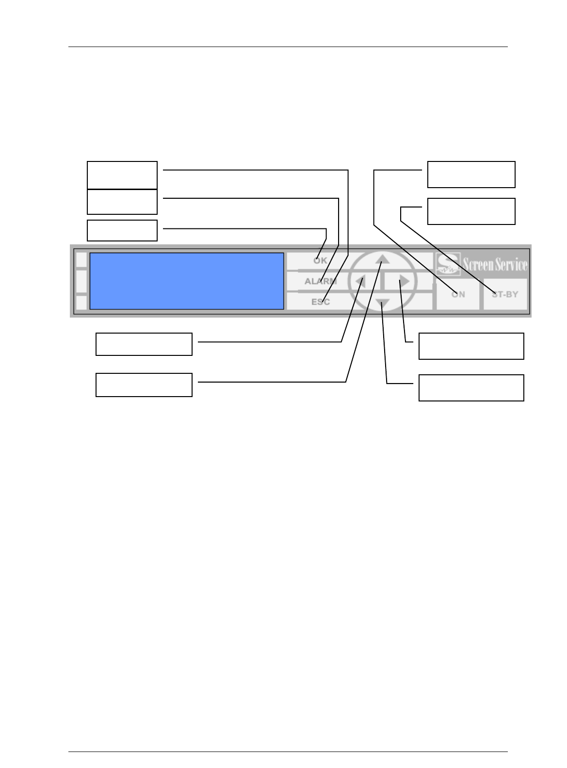
3.1.6 MULTIMETER
The following paragraphs describe the local user interface for ARK1.
This user interface is composed of LCD Display, seven buttons and two status leds.
Here below is depicted the ARK1 Front Panel.
STAND-BY: push this button (lie in wait for two seconds) to put the equipment on
STAND-BY mode. The orange led lights up and the written STAND-BY MODE appears
on the display. The remote Stand-by mode is enforceable only if on JAVA interface this
feature is enabled.
ON: push this button (lie in wait for two seconds) to turn on the equipment. The green
led lights up and the MAIN MENU is displayed.
OK: push this button to select or to confirm the subwindow or the value respectively.
Touching the screen with a finger the green led lights up.
ESC: push this button to quit a submenu and to return to the previous one. Touching the
screen with a finger the green led lights up.
ALARM: when an alarm occurs the RED LED lights up.
UP ARROW: push this botton to scroll up menus or to increase a value. Touching the
screen with a finger the green led lights up.
DOWN ARROW: push this botton to scroll down menus or to decrease a value.
Touching the screen with a finger the green led lights up.
LEFT ARROW: push this botton to move within a string. Touching the screen with a
finger the green led lights up.
RIGHT ARROW: push this botton to move within a string. Touching the screen with a
finger the green led lights up.
OK
ALARM
ESCAPE
ON
STANB-BY
LEFT ARROW
UP ARROW
RIGHT ARROW
DOWN ARROW
Screen Service SDT ARK 1 ECHO Operations
Jan, 2012 v 1.ATSC_FCC Page 3 - 8
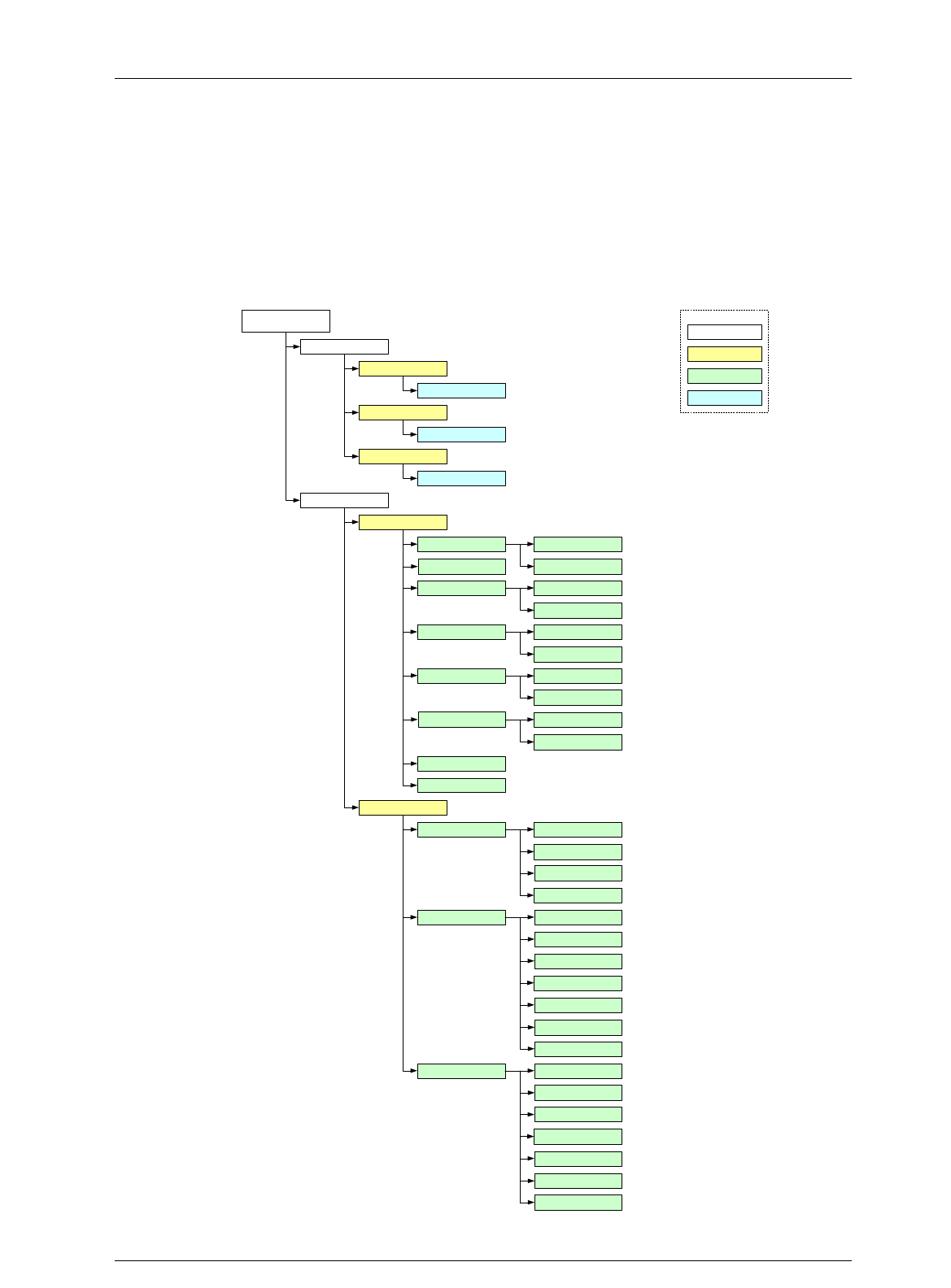
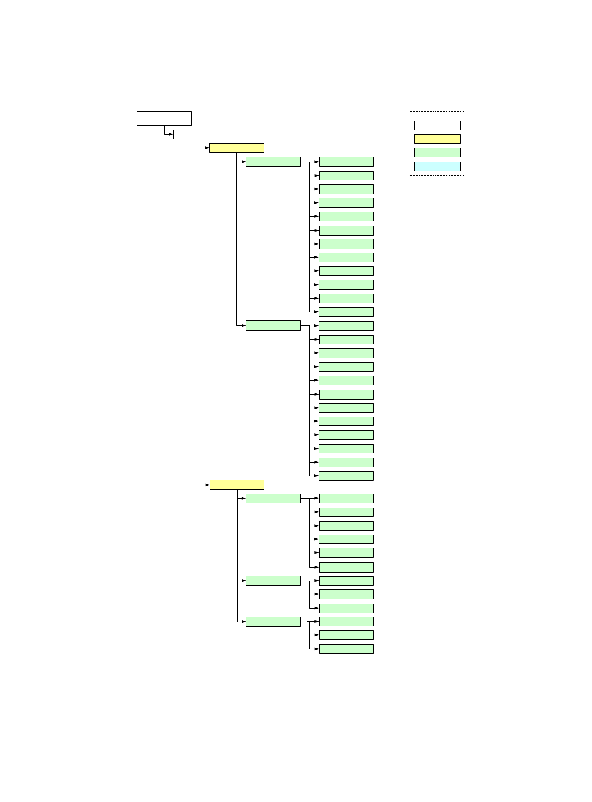
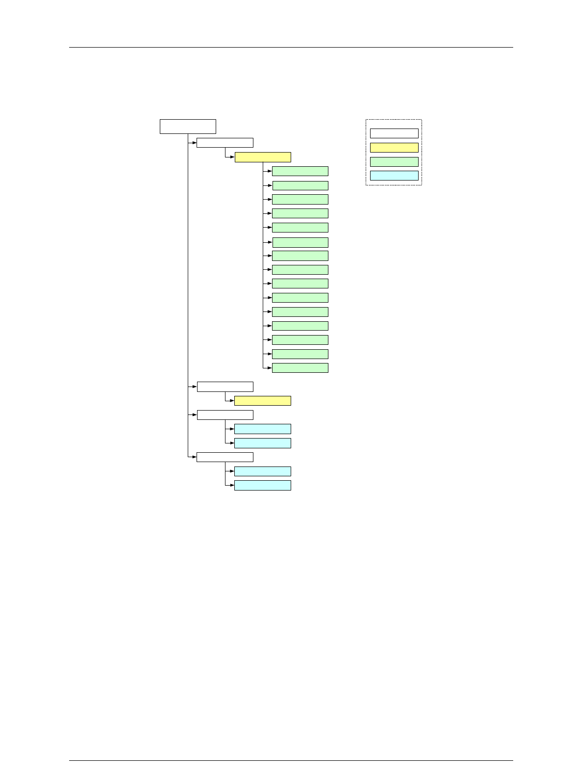
3.1.7 LOCAL INTERRFACE MENU TREE
Figure 1. Local Interface Menu Tree
Main display
menu
Network setup
System Status
IP addr GBE
Gateway GBE
Netmask GBE
System
A1:A2:A3:A4
G1:G2:G3:G4
N1:N2:N3:N4
Actual mode
Amplifier status
Power supply
Temperature
Fans speed
Real Time Clock
Optos status
Relays status
Input
Input
HP input
Type
Channel
Frequency Offset
D. Lock / A.VSync
Input
Lock
Bitrate
Useful
Overflow
Format
Errors
Menu
Multiple choice
Data R
LEGEND
Data W
LP input Input
Lock
Bitrate
Useful
Overflow
Format
Errors
Current Mode A
Current Mode A
Voltage
Current
Case
PSU
FAN 1
FAN 2
Time
Date
Screen Service SDT ARK 1 ECHO Operations
Jan, 2012 v 1.ATSC_FCC Page 3 - 9
Main display
menu
Tuner
Tuner HP
Menu
Multiple choice
Data R
LEGEND
Lock status
Demodulator BER
Viterbi BER
Packet errors
SNR
Constellation
Hierchical Mode
Interleaver
FEC
FFT
Guard Time
Cell ID
Output
Output RF status
Frequency ref
Channel
Offset
FWD power
RFL power
RTP 1 Input
Status
RTP 2
Data W
Tuner LP Lock status
Demodulator BER
Viterbi BER
Packet errors
SNR
Constellation
Hierchical Mode
Interleaver
FEC
FFT
Guard Time
Cell ID
System status
IP Address
Input
Status
IP Address
Screen Service SDT ARK 1 ECHO Operations
Jan, 2012 v 1.ATSC_FCC Page 3 - 10
Modulation
Network
Del Null Pcks
Bandwidth
Constellation
Hierarchical Mode
Interleaver
HP FEC
LP FEC
FFT
Guard Time
Cell ID
Menu
Multiple choice
Data R
LEGEND
Data W
Main display
menu
System status
Alarms
Alams list
Reset system
Change mode
Mode A
Mode B
Yes
No
Time Slice HP
Time Slice LP
MPE FEC HP
MPE FEC LP

Screen Service SDT ARK 1 ECHO Operations
Jan, 2012 v 1.ATSC_FCC Page 3 - 11
3.1.8 BOOT AND WELCOME MESSAGE
Turning on the equipment, the display shows the progress bar as follow:
When the boot is over, the board is ready.
Press ESC to enter the main menu, otherwise after one minute waiting the idle status message
appears.
Screen Service
ARK - ATSC/DIG-IF
System Init
Init : [ ] Wait
Screen Service
ARK - ATSC/DIG-IF
Boot FPGA
Init : [ ] Wait
Screen Service
ARK - ATSC/DIG-IF
Up Converter check
Init : [ ] Wait
Screen Service
ARK - ATSC/DIG-IF
Start system
Init : [ ] Wait
Screen Service
ARK - ATSC/DIG-IF
Start system
Init : [ ] Ready
Screen Service
ARK - ATSC/DIG-IF
10.77.98.44
Ready

Screen Service SDT ARK 1 ECHO Operations
Jan, 2012 v 1.ATSC_FCC Page 3 - 12
3.2 IDLE MENU
This menu appears after one minute waiting from the last touch. Information contained in the Idle Menu
are described in next table.
Table 1. Local User Interface: Idle Menu
Information
Description
Operating mode
DIGITAL IF: Heterodyne Transposer
ATSC: Re-broadcasting ATSC
Modulator
AGC Mode
(only in DIGITAL-IF mode)
ANA: Analog
DIG: Digital
Input Power and Channel
(only in DIGITAL-IF mode)
Din: digital input power and channel
Ain: analog input power and channel
Output Power and Channel
Dout: digital output power and channel
Aout: analog output power and channel
Out: output power and channel
UTC
Time and date coming from GPS receiver
Press ESC to enter the MAIN MENU.
ARK -DIGITAL-IF (DIG)
DIn 23.1dBm CH:22
Dout 23.1dBm CH:22
UTC: 14:11 08/11/06
ARK - ATSC
InHP: ASI1
Out 17.1dBm CH:22
UTC: 14:11 08/11/06
ARK -DIGITAL-IF (ANA)
AIn 23.1dBm CH:22
Aout 23.1dBm CH:22
UTC: 14:11 08/11/06

Screen Service SDT ARK 1 ECHO Operations
Jan, 2012 v 1.ATSC_FCC Page 3 - 13
3.2.1 MAIN MENU
This menu shows five SUBMENUS. It is possible to view them sliding the menu up and down, with the
UP or DOWN ARROWS, and to select one of them by pushing on the OK button.
Submenus contained in the Main Menu are described in next table.
Submenu
Description
Network setup
Enter this submenu to change:
Board IP address
Gateway address
Netmask
System Status
Enter this submenu to monitor:
System status
Auxiliary and RF input statistics
Tuner status
Output status and settings
Actual modulation parameters
All information are refreshed every 5
seconds.
Alarms
Enter this submenu to view the alarm list
Reset system
Enter this submenu to reset the device.
Change mode
Enter this submenu to change operating
mode (A or B).
Change Mode
Network setup
System Status
/ OK:Enter
/

Screen Service SDT ARK 1 ECHO Operations
Jan, 2012 v 1.ATSC_FCC Page 3 - 14
3.3 LCD alarms
Through the LCD Alarms mask it is possible to select which alarm has to be notified on LCD display.
The alarm button is lighted and when an alarm condition occurs, alarms status is displayed in the
Alarms submenu.
The following table lists the alarms messages displayed on LCD, associated to the corresponding alarm
(refer to Alarms paragraph for further information about alarms and their masks).
Table 2.
Alarms descriptions list
Alarm
Alarm Message
Up converter Osc. Unlock
UPCV not locked
PS Voltage out of range
PS V out of range
PS Current out of range
PS I out of range
Absolute Power Limiter
Abs. pwr high
Communication error
UPCV dialog error
Temperature High Alarm
Temperature high
Temperature Level-3dB
Temp alarm (-3dB)
Temperature High Warning
Temp warning
Forward Power High
FWD power high
Forward Power Low Warning
FWD low warning
Forward Power Low Alarm
FWD low alarm
Reflex Power High
RFL power high
Fan Speed
Fans warning
S/N level
RF in S/N low
GPS Lock
GPS not locked
GPS Communication Error
GPS dialog error
Signal 10 MHz Lock
10MHz not detected
Signal 146 MHz Lock
120MHz not detected
Signal 960 MHz Lock
960MHz not detected
Down Converter Osc. Unlock
DWCV not locked
No RF Input
In. not detected
RF Input Squelch
RF in Squelch
RF Digital Ber Alarm
RF BER high
File System Error
FS wrong
Bad File in File system
File error
ATSC 1PPS Lock
PPS not detected
ATSC PPS Phase
PPS phase wrong
ATSC System Delay
Sys delay wrong
ATSC No MIP
MIP not detected

Screen Service SDT ARK 1 ECHO Operations
Jan, 2012 v 1.ATSC_FCC Page 3 - 15
Alarm
Alarm Message
ATSC No Input
In. not detected
FPGA Boot alarm
FPGA boot err
Warm up alarm
Sys. warm up
Screen Service SDT ARK 1 ECHO Operations
Jan, 2012 v 1.ATSC_FCC Page 3 - 16
3.4 JAVA REMOTE GRAPHIC USER INTERFACE
The Java Graphic User Interface, stored in the board File System, is downloaded to the local PC
every time the user connects to the board with a Web Browser. A proper Java Virtual Machine is
needed; refer to the Appendix B for a description of supported Java and Internet Browsers.
3.4.1 JAVA INTERFACE OVERVIEW
The following figure shows the main control switch of the Java User Interface. It allows the
switching between control pages for settings and monitoring the device.
Figure 2. Java main control switch
The following controls are provided:
System commands bar allows the enabling of the following commands:
Connect: connects/disconnects the local machine to Ark1 system
Save: allows to save the device configuration.
Load: allows to load the last saved device configuration.

Screen Service SDT ARK 1 ECHO Operations
Jan, 2012 v 1.ATSC_FCC Page 3 - 17
Figure 3. System commands bar
Operation pages bar allows to switch between the following operative sections:
General: allows the enable the Stand-by mode through the LCD Button, to reset the
device and to locally download the *.jar file.
Input: shows ASI and GBE input statistics (Re-broadcasting Hierarchical ATSC
Modulator).
Tuner: allows to monitor the RF input and to configure operative modes (Analog/Digital
Television Heterodyne Transposer and Re-broadcasting Hierarchical ATSC Modulator).
Modulation: allows to monitor and to set the ATSC modulation parameters (Re-
broadcasting Hierarchical ATSC Modulator).
Mod. Pha.: allows to manage linear pre-correction curves.
AM/PM: allows to manage AM/PM pre-correction curves.
Outputs: allows to set output parameters, specific for each operative mode, and to
monitor the hardware status (Analog/Digital Television Heterodyne Transposer and Re-
broadcasting Hierarchical ATSC Modulator).
Network: allows the Network management and the RTP in/out parameters setting.
GPS: shows received GPS statistics.
Alarms: provides a grid where to set alarms masks for LCD, Graphic User Interface,
Events, Relays, Traps and RF Off.
Events: shows the board events.
Figure 4. Operation pages bar
System menu allows the access to the same commands and pages as System commands and
Operation pages bars plus management options, help and version windows (refer to Option sub-
menu paragraph).
Figure 5. System menu
A brief description of all the provided indicators and controls follows in the next paragraphs.
The column named R/H specifies if the indicator/command belongs to the Re-broadcasting
ATSC modulator mode rather than belonging to the Analog/Digital Television Heterodyne
Transposer mode.
Screen Service SDT ARK 1 ECHO Operations
Jan, 2012 v 1.ATSC_FCC Page 3 - 18
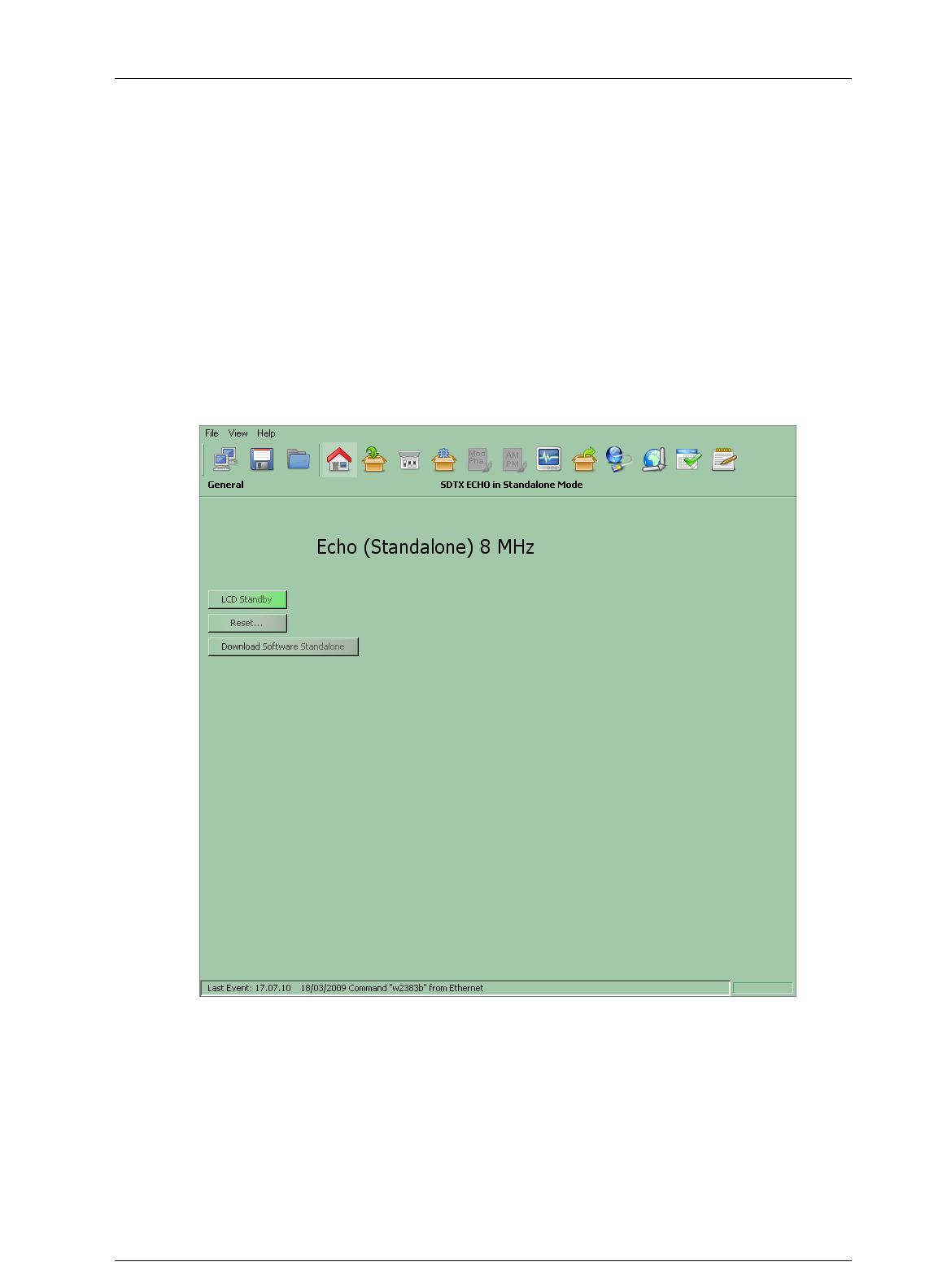
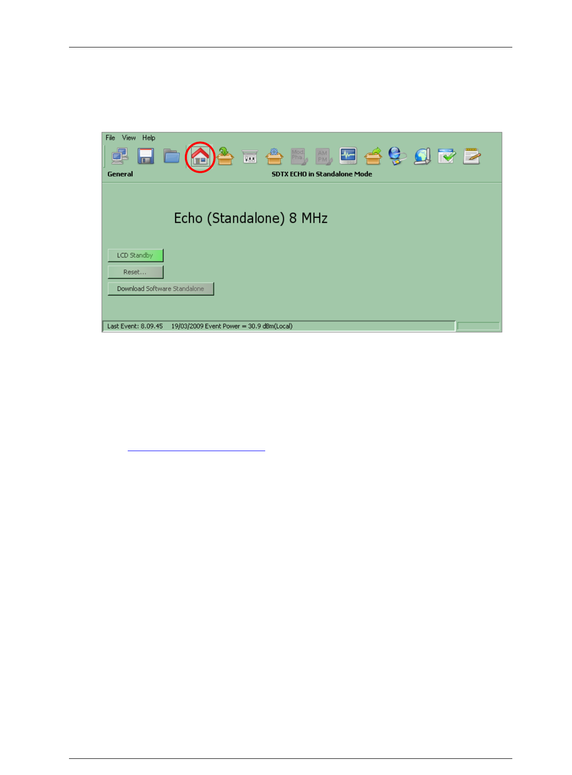
3.4.1.1 General
Click on General button icon, highlighted in the nex figure, to access the general window.
Figure 6. General window
The General window provides a general description of the device and allows the access to a
subset of commands through the following button icons:
Reset: resets the device.
LCD Standby: enables the LCD Stand-by button.
Download Software Standalone: performs a local download of the *.jar file (refer to
Download Software Standalone paragraph).
Screen Service SDT ARK 1 ECHO Operations
Jan, 2012 v 1.ATSC_FCC Page 3 - 19
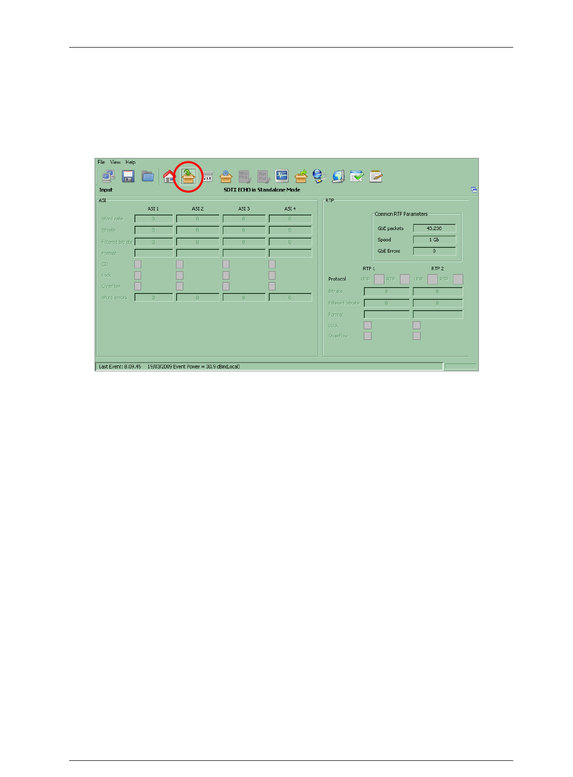
3.4.1.2 Input
Click on Input button icon, highlighted in the nex figure, to access the input statistics window.
Figure 7. Input window
The Input window allows the monitoring of auxiliary inputs of Re-broadcasting ATSC Modulator.
Input Transport Stream monitoring of four ASI and two RTP channels on GBE port are provided.

Screen Service SDT ARK 1 ECHO Operations
Jan, 2012 v 1.ATSC_FCC Page 3 - 21
Table 3. Input window
Box
Parameter /
Control
Description
Admitted Ranges / Values
R/H
ASI
Word rate
ASI input word rate. 10 bit word rate of ASI input (Ref. to CEI EN 50083-9).
Approximately 27 Mword/s
R
ASI
Bitrate [bit/s]
ASI input bitrate.
R
ASI
Filtered
bitrate[bit/s]
Bitrate actually used by the modulator.
Zero when the input is not selected
Equal to the total bitrate, when Delete
Null Packets disabled
Less than total bitrate, when Delete
Null Packets enabled
R
ASI
Format
Format of received TS Packets (Ref. to CEI EN 50083-9).
188 Bytes
240 Bytes
R
ASI
CD
ASI Carrier detect.
Green: Detected
Grey: Not detected
R
ASI
Lock
ASI lock status. The input Transport Stream is unlocked when more than two consecutive Sync Byte are
missed then five consecutive Sync Bytes must occur to regain the lock (Ref. to ETSI ETR-291)
Green: Locked
Grey: Not locked
R
ASI
Overflow
ASI input overflow indicator. This alarm condition occurs when the input bitrate exceeds the capability of
the modulation (Ref. to ETSI EN 300 744).
Red: Alarm
Grey: No alarms
R

Screen Service SDT ARK 1 ECHO Operations
Jan, 2012 v 1.ATSC_FCC Page 3 - 22
Box
Parameter /
Control
Description
Admitted Ranges / Values
R/H
ASI
Word Errors
Total amount of ASI wrong words received.
R
RTP
Protocol
Ethernet input packets protocol.
UDP
RTP
R
RTP
Bitrate [bit/s]
Bitrate of TS from Ethernet input.
R
RTP
Filtered
bitrate[bit/s]
Bitrate actually used by the modulator.
Zero when the input is not selected
Equal to the total bitrate, when Delete
Null Packets disabled
Less than total bitrate, when Delete
Null Packets enabled
R
RTP
Format
Format of received TS Packets (Ref. to CEI EN 50083-9).
188 Bytes
240 Bytes
R
RTP
Lock
TS lock status. The input Transport Stream is unlocked when more than two consecutive Sync Byte are
missed then five consecutive Sync Bytes must occur to regain the lock (Ref. to ETSI ETR-291)
Green: Locked
Grey: Not locked
R
RTP
Sequence
error
Ethernet input Sequence error alarm status. This alarm condition occurs when an error in the sequence
of input packets at IP level occurs.
Red: Alarm
Grey: No alarms
R

Screen Service SDT ARK 1 ECHO Operations
Jan, 2012 v 1.ATSC_FCC Page 3 - 23
Box
Parameter /
Control
Description
Admitted Ranges / Values
R/H
RTP
Overflow
GbE input overflow alarm status. This alarm condition occurs when the input bitrate exceeds the
capability of the modulation (Ref. to ETSI EN 300 744).
Red: Alarm on
Grey: Alarm off
R
RTP
GBE packets
Total amount of good Ethernet frames received.
R
RTP
Speed
Ethernet connection speed. No duplex information is provided.
10 Mbit//s
100 Mbit//s
1 Gbit//s
R
RTP
GBE errors
Total amount of bad Ethernet frames received.
R
Screen Service SDT ARK 1 ECHO Operations
Jan, 2012 v 1.ATSC_FCC Page 3 - 24
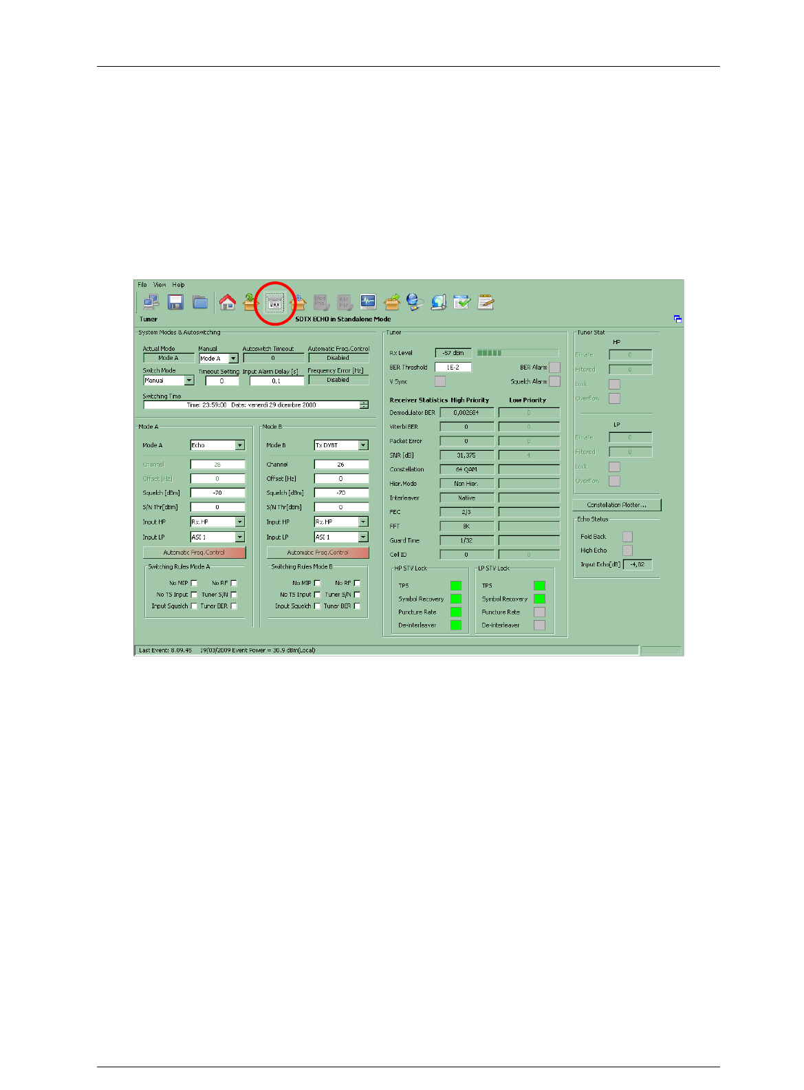
3.4.1.3 TUNER
Click on Tuner button icon, highlighted in the nex figure, to access the tuner window.
Figure 8. Tuner window
This window provides commands that allow the selection of working modes, the management
and selection of inputs, and the monitoring of quality and level of input RF signals.
The Tuner window is divided in the following boxes:
System Mode & Autoswitching;
Mode A;
Switching Rules Mode A;
Mode B;
Switching Rules Mode B;
Tuner;
Tuner Stat.
3.4.2 Modes management
These commands allow the setting of working modes and switch selection rules.
The following table shows the commands and indicators available for modes management.

Screen Service SDT ARK 1 ECHO Operations
Jan, 2012 v 1.ATSC_FCC Page 3 - 25
Table 4. Modes management
Box
Parameter /
Control
Description
Admitted Ranges / Values
R/H
System Mode &
Autoswitching
Actual mode
Current operating mode.
Mode A
Mode B
R/H
System Mode &
Autoswitching
Manual
Selector of mode used when Manual Switch mode is selected.
Mode A
Mode B
R/H
System Mode &
Autoswitching
Switch mode
Selector of the switch mode rules.
Refer to
Switching modes rules
paragraph for a detailed description of the switching rules and
conditions.
Manual
Auto
Opto
Time
R/H
System Mode &
Autoswitching
Autoswitch
Timeout
When Auto Switch Mode is enabled shows the time to wait for switching. If the used input regains
lock before the countdown reaches 0 the switch is blocked and device keeps the same mode.
Countdown from 255 to 0
R/H
System Mode &
Autoswitching
Timeout
setting
Time to wait for switching.
Refer to
Switching modes rules
paragraph for a detailed description of the switching rules.
Countdown from 255 to 0 second
R/H
System Mode &
Autoswitching
Switching Time
Time and date of modes switching when Time Switch mode is enabled.
R/H

Screen Service SDT ARK 1 ECHO Operations
Jan, 2012 v 1.ATSC_FCC Page 3 - 26
Box
Parameter /
Control
Description
Admitted Ranges / Values
R/H
System Mode &
Autoswitching
Frequency
Error [Hz]
Frequency error automatically corrected.
Note: When the frequency error exceeds the dynamics, STV might loose the lock.
Out of range: input frequency error
exceeds 166 KHz dynamics. Set a +/-
166 KHz input freq. offset in order to
true up the dynamics.
Min: -83 KHz
Max: +83KHz
R/H
System Mode &
Autoswitching
Automatic
Freq. Control
Shows Automatic Freq. Control status.
Enabled
Disabled
R/H
Mode A / Mode B
S/N Thr [dBm]
Signal to Noise alarm threshold
Min: -10 dBm
Max: –50 dBm
R/H
Mode A / Mode B
Automatic
Freq. Control
Enabling button of the AFC (refer to Appendix A for further information)
Enabled
Disabled
R/H
Mode A / Mode B
Mode A / B
Selector of working mode.
Three different working modes are provided:
Analog Television Heterodyne Transposer;
Digital Television Heterodyne Transposer;
Re-broadcasting ATSC Modulator.
Rep. Analog
Rep. Digital
Tx ATSC
R/H

Screen Service SDT ARK 1 ECHO Operations
Jan, 2012 v 1.ATSC_FCC Page 3 - 27
Box
Parameter /
Control
Description
Admitted Ranges / Values
R/H
Mode A / Mode B
Channel
Selector of the UHF input channel used as RF input.
Min: 21
Max: 69
R/H
Mode A / Mode B
Offset [Hz]
Frequency offset from the channel center frequency of the RF input. 1 Hz step variation.
Min: -4 MHz
Max: 4 MHz
R/H
Mode A / Mode B
Squelch
[dBm]
Squelch alarm threshold expressed in dBm. Input is squelched when the RF level is under this
treshold.
Min: -70
Max: -20
R/H
Mode A / Mode B
Input HP
Selector of TS input for re-modulator used for Not Hierarchical or High Priority.
ASI 0
ASI 1
ASI 2
ASI 3
RX.HP
RX.LP
GbE1
GbE2
R
Mode A / Mode B
Input LP
Selector of TS input for re-modulator used for Low Priority in a Hierarchical Modulation.
R

Screen Service SDT ARK 1 ECHO Operations
Jan, 2012 v 1.ATSC_FCC Page 3 - 28
Box
Parameter /
Control
Description
Admitted Ranges / Values
R/H
Switching Rules
Mode A / B
No RF, No TS
Input, Tuner
S/N, Input
Squelch, Tuner
BER
Autoswitch alarms mask. Refer to
Switching modes rules
paragraph for a detailed description of the
switching rules and conditions.
R/H

Screen Service SDT ARK 1 ECHO Operations
Jan, 2012 v 1.ATSC_FCC Page 3 - 29
3.4.3 Modes switching rules
Four switching rules are provided in order to cover different requirements:
Manual: switch between mode A and mode B by selecting one mode using the Manual
Selector. The selected mode is always enabled until the user selects the other one.
Auto: switch between mode A and mode B using the rules shown in the
following table. One mode is enabled until at least one of the alarms associated
to the enabled autoswitch rules is risen, then a countdown starts and, if the
parameter doesn’t regain a normal status during the timeout, the device
switches to the other mode.
Table 5. Autoswitch rules
Mode
Autoswitch rules
Heterodyne
Analog
repeater
No RF: No good Analog RF input. Video Carrier not locked. It is
associated to the No RF Input alarm.
Input Squelch: Received signal level under the squelch threshold. It is
associated to the RF Input Squelch alarm.
Heterodyne
Digital
repeater
No RF: video carrier not locked by the ATSC receiver. It is associated to
the No RF Input alarm.
Input Squelch: Received signal level under the squelch threshold. It is
associated to the RF Input Squelch alarm.
Tuner BER: Bit Error Rate after demodulator over the BER threshold. It
is associated to the RF Digital BER Alarm alarm.
Tuner S/N: Signal to Noise ratio under the S/N threshold. It is associated
to the S/N Level alarm.
TX ATSC
No RF: video carrier not locked by the ATSC receiver. It is associated to
the No RF Input alarm.
Input Squelch: Received signal level under the squelch threshold. It is
associated to the RF Input Squelch alarm.
Tuner BER: Bit Error Rate after demodulator over the BER threshold. It
is associated to the RF Digital BER Alarm alarm.
Tuner S/N: Signal to Noise ratio under the S/N threshold. It is associated
to the S/N Level alarm.
No TS Input: selected TS input not locked. TS input Alarm should be
enabled in the RF Off alarms mask. It is associated to the ATSC No Input
alarm.
Opto: switch between mode A and mode B by selecting one mode using the
Opto 1 input with the following rules:
o 1 – Open: Mode A.
o 0 – Closed: Mode B.
Time: switch between mode A and mode B at the specified Date and Time. Switching
will happen only one time from A to B. In order to set the Switching Time, select hours,
minutes, seconds, days, months and years, and click on up/down arrows to
increase/decrease them.

Screen Service SDT ARK 1 ECHO Operations
Jan, 2012 v 1.ATSC_FCC Page 3 - 30
3.4.4 Tuner management
These commands allow the setting of BER alarm threshold and monitoring of RF input status.
The following table shows all the commands and indicators available.

Screen Service SDT ARK 1 ECHO Operations
Jan, 2012 v 1.ATSC_FCC Page 3 - 31
Table 6. Tuner management
Box
Parameter /
Control
Description
Admitted Ranges / Values
R/H
Tuner Stat
Bitrate [bit/s]
Bitrate of TS from RF input (HP and LP).
R/H
Tuner Stat
Filtered [bit/s
Bitrate actually used by the modulator.
Zero when the input is not selected
Equal to the total bitrate, when Delete
Null Packets disabled
Less than total bitrate, when Delete
Null Packets enabled
R/H
Tuner Stat
Lock
HP/LP input lock status. The input Transport Stream is locked when no more than two consecutive Sync
Byte are missed.
Green: Locked
Grey: Not locked
R/H
Tuner Stat
Overflow
HP/LP input overflow alarm status. This alarm condition occurs when the input bitrate exceeds the
capability of the modulation (Ref. to ETSI EN 300 744).
Red: Alarm
Grey: No alarms
R/H
Turner Main
Rx level
RF input rx level.
R/H
Turner Main
BER
Threshold
Demodulator Bit Error Rate alarm threshold.
Min: 0.000001
Max: 0.06
R/H
Turner Main
BER
Threshold
Demodulator Bit Error Rate alarm threshold.
Min: 0.000001
Max: 0.06
R/H

Screen Service SDT ARK 1 ECHO Operations
Jan, 2012 v 1.ATSC_FCC Page 3 - 32
Box
Parameter /
Control
Description
Admitted Ranges / Values
R/H
Turner Main
Squelch
alarm
Squelch alarm status.
Red: Alarm
Grey: No alarms
R/H
Turner Main
V Sync
Analog signal lock status. The PAL detector has been implemented through the detection of the video
carrier synchronization at 15,625 Hz.
Green: Good Analog
Grey: Bad Analog
R/H
HP/LP Receiver
Statistics
Demodulator
BER
Demodulator bit error rate.
R/H
HP/LP Receiver
Statistics
Viterbi BER
Viterbi byte error rate.
R/H
HP/LP Receiver
Statistics
Packet Error
Packet error counter.
R/H
HP/LP Receiver
Statistics
SNR [dB]
Signal to Noise Ratio.
R/H
HP/LP Receiver
Statistics
Constellation
Constellation for current modulation scheme..
QPSK
16-QAM
64-QAM
R/H

Screen Service SDT ARK 1 ECHO Operations
Jan, 2012 v 1.ATSC_FCC Page 3 - 33
Box
Parameter /
Control
Description
Admitted Ranges / Values
R/H
HP/LP Receiver
Statistics
Hier. Mode
Hierarchy information for current scheme.
NH
a=1
a=2
a=4
R/H
HP/LP Receiver
Statistics
Interleaver
Interleaver type.
Native
In-depth
R/H
HP/LP Receiver
Statistics
FEC
HP/LP stream code rate.
1/2;
2/3;
1/4;
5/6;
7/8.
R/H
HP/LP Receiver
Statistics
FFT
Transmission mode.
2K;
4K;
8K.
R/H

Screen Service SDT ARK 1 ECHO Operations
Jan, 2012 v 1.ATSC_FCC Page 3 - 34
Box
Parameter /
Control
Description
Admitted Ranges / Values
R/H
HP/LP Receiver
Statistics
Guard Time
Guard interval.
1/32;
1/16;
1/8;
1/4.
R/H
HP/LP Receiver
Statistics
Cell ID
Cell ID
R/H
HP/LP STV Lock
TPS
TPS were confirmed decoded.
Green: Locked;
Grey: Not locked.
R/H
HP/LP STV Lock
Symbol
Recovery
Symbol recovery loop locked.
R/H
HP/LP STV Lock
Puncture
Rate
Puncture rate found.
R/H
HP/LP STV Lock
De-
Interleaver
De-interleaver locked.
R/H
General
Constellation
plotter
Plotter of HP and LP constellations
R/H
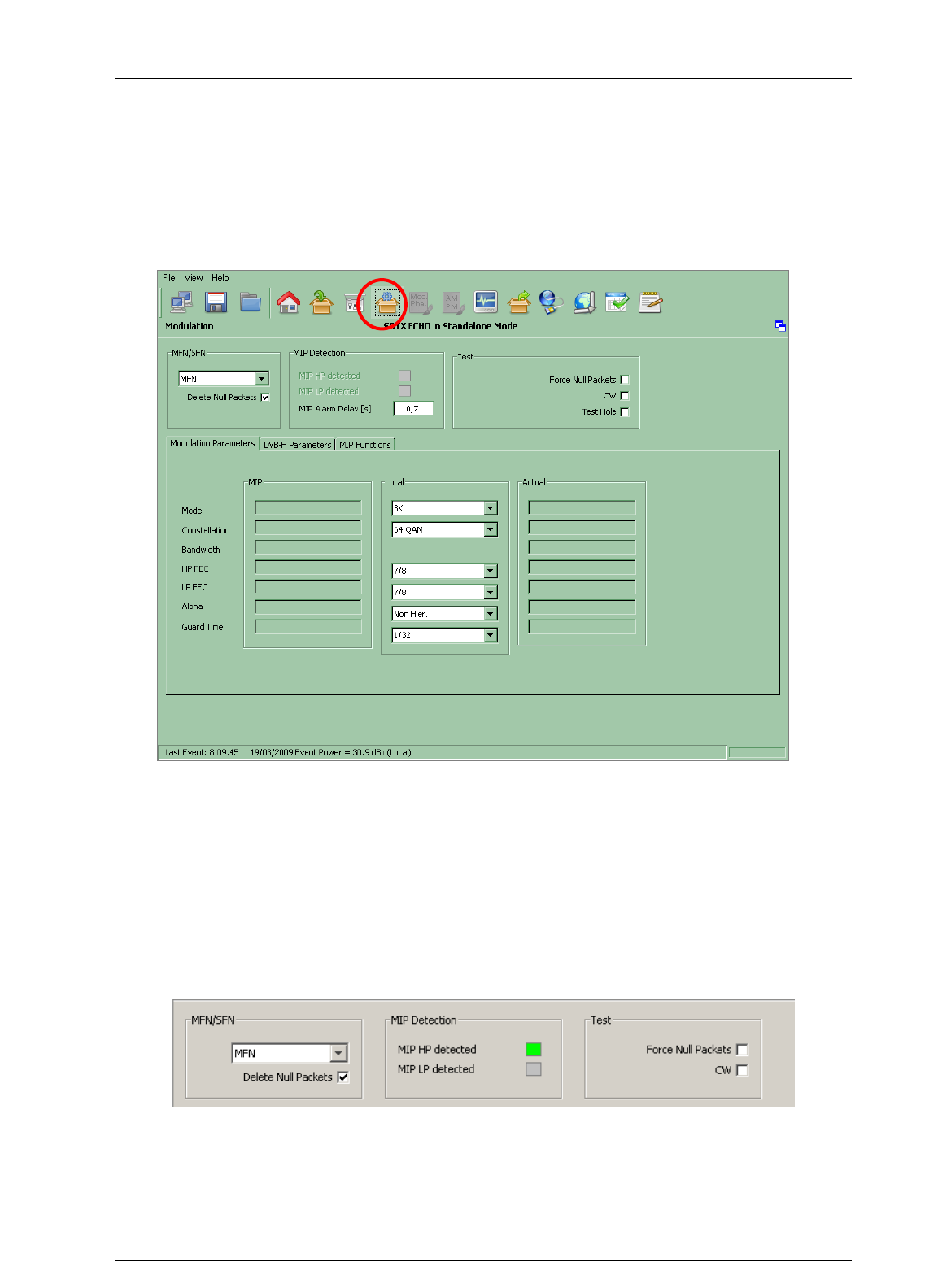
Screen Service SDT ARK 1 ECHO Operations
Jan, 2012 v 1.ATSC_FCC Page 3 - 35
3.4.5 MODULATION
Click on Modulation button icon, highlighted in the nex figure, to access the modulation window.
Figure 9. Modulation window: modulation parameters
The Modulation window allows actual modulation parameters monitoring and modulator
setting/monitoring. These settings are always editable but are applied only when the re-
modulator working mode is enabled.
3.4.6 Modulator management
These commands and indicators allow the setting and monitoring of modulator’s synchronization
options, MIP detector and the enabling of Test options.
Figure 10. Modulator management

Screen Service SDT ARK 1 ECHO Operations
Jan, 2012 v 1.ATSC_FCC Page 3 - 36
Table 7. Modulation management
Box
Parameter /
Control
Description
Admitted Ranges / Values
R/H
MFN / SFN
MFN/SFN
Selector of Network‟s Transmitters Synchronization.
Refer to
Network Synchronization parameter setting
paragraph.
MFN
MFN MIP
SFN
SFN Local
R
MFN / SFN
Delete Null
Packets
Delete null packets enabling check box.
In SFN and SFN Local transmission modes, this option is enabled by default.
In MFN and MFN MIP transmission modes, this option is disabled by default.
Checked: Enabled
Not checked: Disabled
R
Mip Detection
MIP HP/LP
detected
Detection of MIP packets in HP/LP streams.
Green: Detected
Grey: Not detected
R

Screen Service SDT ARK 1 ECHO Operations
Jan, 2012 v 1.ATSC_FCC Page 3 - 37
Box
Parameter /
Control
Description
Admitted Ranges / Values
R/H
Mip Detection
MIP Alarm
Delay [s]
Time to wait for No MIP alarm rising expressed in seconds (refer to
Alarms
paragraph).
Note: It is highly recommended to set a MIP Alarm Delay value different from zero as to allow the
input signal locking.
Min: 1 s
Max: 25.5 s
R
Test
Force Null
Packets
Null data packets transmission enabling check box.
Checked: Enabled
Not checked: Disabled
R
Test
CW
CW test enabling check box.
Checked: Enabled
Not checked: Disabled
R/H
Test
Test Hole
Test Hole enabling check box.
Checked: Enabled
Not checked: Disabled
R/H

Screen Service SDT ARK 1 ECHO Operations
Jan, 2012 v 1.ATSC_FCC Page 3 - 38
3.4.7 Network Synchronization parameters setting
Four Network Synchronization modes are available:
Multi Frequency Network mode using local parameters (MFN):
The transmitter is not synchronized with any network. No input MIP is
needed and Clock Reference can be internal.
Multi Frequency Network mode using MIP parameters (MFN MIP):
The transmitter is not synchronized with any network but MIP sets the
modulation parameters. Input MIP is needed and Clock Reference can
be internal.
Single Frequency Network mode (SFN): The transmitter is
synchronized with a Network of transmitters on the same frequency.
MIP is needed and Clock Reference must be external or GPS.
Single Frequency Network mode using local parameters (SFN
Local): The transmitter is synchronized with a Network of transmitters
but for testing purposes the modulation parameters are set locally.
Input MIP is needed for 1PPS synchronization and Clock Reference
must be external or GPS.
The following table provides a description of the available parameters setting
for the network modes.
Table 8. Network Synchronization parameters setting
Parameters
MFN
SFN
MFN + MIP
SFN Local
Mode
Local
MIP
MIP
Local
Constellation
Local
MIP
MIP
Local
FEC HP
Local
MIP
MIP
Local
FEC LP
Local
MIP
MIP
Local
Transmission
Local
MIP
MIP
Local
Time Slicing
HP
Local
MIP
MIP
Local
Time Slicing
LP
Local
MIP
MIP
Local
Guard Time
Local
MIP
MIP
Local
BW
Local
MIP
MIP
Local
Alpha
Local
MIP
MIP
Local
Input HP
Local
Local
Local
Local
Input LP
Local
Local
Local
Local
Interleaver
Local (for 8k
mode only native)
MIP
MIP
Local (for 8k
mode only
native)
MPE FEC HP
Local
MIP
MIP
Local
MPE FEC LP
Local
MIP
MIP
Local
Cell Id enable
Local
Local
Local
Local
Cell Id
Local (only if
enabled)
MIP or Local
(only if enabled)
Function from MIP
can be enabled or
disabled
MIP or Local
(only if enabled)
Function from MIP
can be enabled or
disabled
Local (only if
enabled)
Frequency
Offset
Local
MIP or Local
(only if enabled)
Function from MIP
can be enabled or
disabled
MIP or Local
(only if enabled)
Function from MIP
can be enabled or
disabled
Local
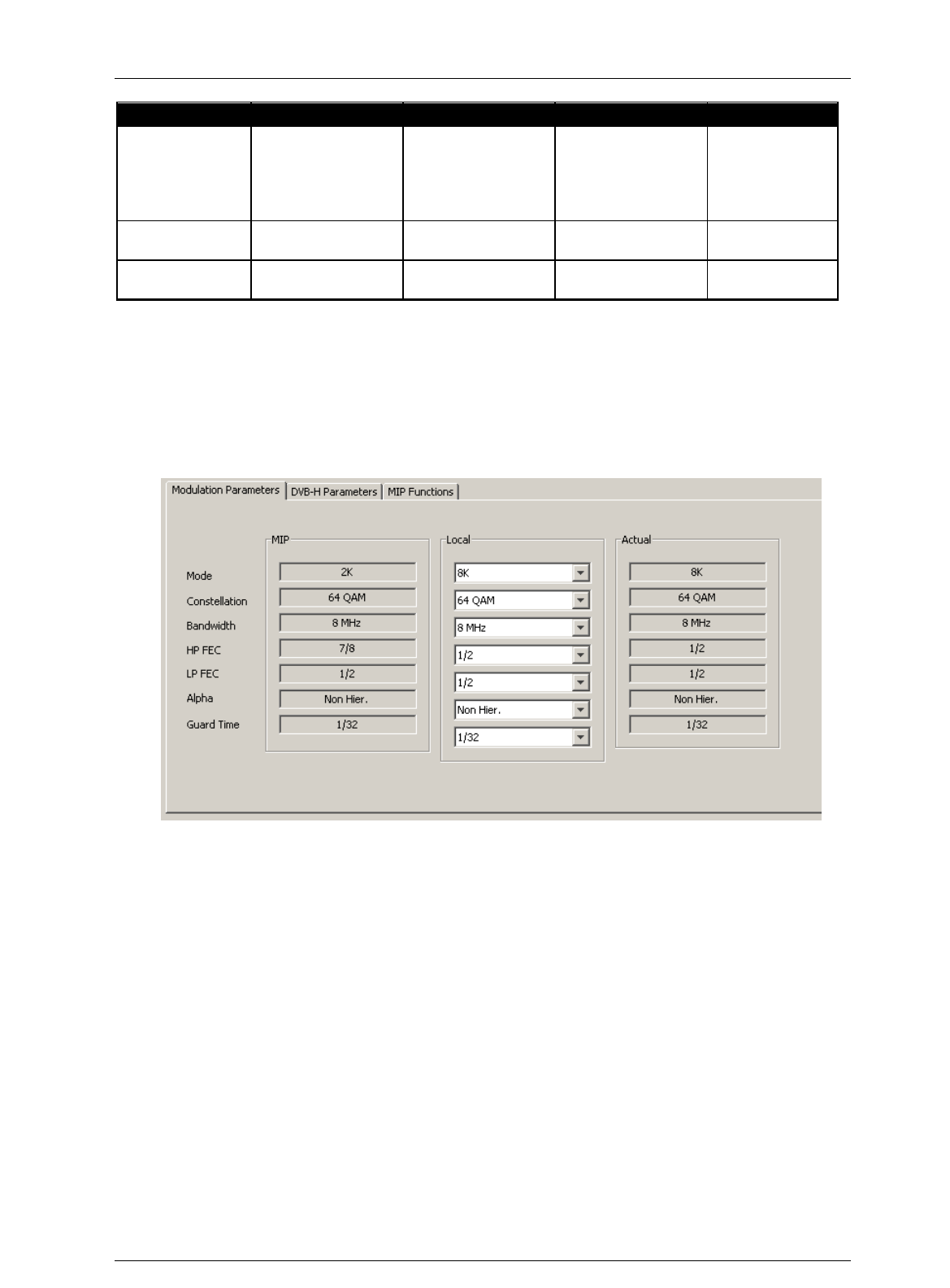
Screen Service SDT ARK 1 ECHO Operations
Jan, 2012 v 1.ATSC_FCC Page 3 - 39
Parameters
MFN
SFN
MFN + MIP
SFN Local
Time Offset
Local
MIP or Local
(only if enabled)
Function from MIP
can be enabled or
disabled
MIP or Local
(only if enabled)
Function from MIP
can be enabled or
disabled
Local
Del Null
Packet
Can be enabled or
disabled
Must be disabled
Can be enabled or
disabled
Must be
disabled
Frequency
Reference
Can be internal or
external
Must be external
Can be internal or
external
Must be
external
3.4.8 Modulation parameters
These commands and indicators allow the setting of modulation parameters,
the monitoring of parameters carried by MIP in SFN configuration and of actual
modulation parameters.
Figure 11. Modulation parameters

Screen Service SDT ARK 1 ECHO Operations
Jan, 2012 v 1.ATSC_FCC Page 3 - 40
Table 9. Modulation parameters
Box
Parameter/
Control
Description
Admitted Ranges / Values
R/H
MIP
Mode
Transmission mode: set by MIP.
2K
4K
8K
R
Local
Transmission mode: locally set.
R
Actual
Current transmission mode
R
MIP
Bandwidth
Bandwidth: set by MIP.
7MHz
8MHz
6MHz
5MHz
R
Actual
Current bandwidth.
R
MIP
Constellation
Constellation for current modulation scheme: set by MIP.
QPSK
16-QAM
64-QAM
R
Local
Constellation for current modulation scheme: locally set.
R
Actual
Current constellation for modulation scheme.
R
MIP
Bandwidth
Bandwidth: set by MIP.
7MHz
R
Local
Bandwidth: locally set.
R

Screen Service SDT ARK 1 ECHO Operations
Jan, 2012 v 1.ATSC_FCC Page 3 - 41
Box
Parameter/
Control
Description
Admitted Ranges / Values
R/H
Actual
Current bandwidth.
8MHz
6MHz
5MHz
R
MIP
HP/LP FEC
HP/LP stream code rate: set by MIP.
1/2
2/3
3/4
5/6
7/8
R
Local
HP/LP stream code rate: locally set.
R
Actual
Current HP/LP stream code rate.
R
MIP
Alpha
Hierarchy information for current scheme: set by MIP.
NH;
a=1;
a=2;
a=4.
R
Local
Hierarchy information for current scheme: locally set.
R
Actual
Current Hierarchy information for current scheme.
R
MIP
Guard Time
Guard interval: set by MIP.
1/32
R
Local
Guard interval: locally set.
R

Screen Service SDT ARK 1 ECHO Operations
Jan, 2012 v 1.ATSC_FCC Page 3 - 42
Box
Parameter/
Control
Description
Admitted Ranges / Values
R/H
Actual
Current guard interval.
1/16
1/8
1/4
R
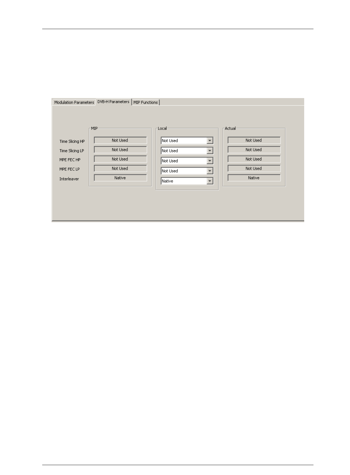
Screen Service SDT ARK 1 ECHO Operations
Jan, 2012 v 1.ATSC_FCC Page 3 - 43
3.4.9 ATSC parameters
These commands and indicators allow the setting of options for ATSC transmission, the
monitoring of parameters carried by MIP in SFN configuration and of actual ATSC options.
Figure 12. ATSC parameters

Screen Service SDT ARK 1 ECHO Operations
Jan, 2012 v 1.ATSC_FCC Page 3 - 44
Table 10.
ATSC parameters.
Box
Parameter/
Control
Description
Admitted Ranges / Values
R/H
MIP
Time Slicing
HP/LP
Enabling of time slice transmission of the HP/LP stream: set by MIP.
Used
Not used
R
Local
Enabling of time slice transmission of the HP/LP stream: locally set.
R
Actual
Current enabling status of time slice transmission.
R
MIP
MPE FEC
HP/LP
HP/LP MPE-FEC enabling: set by MIP.
Used
Not used
R
Local
HP/LP MPE-FEC enabling: locally set.
R
Actual
Current HP/LP MPE-FEC enabling status.
R
MIP
Interleaver
Interleaver type selector: set by MIP.
Used
Not used
R
Local
Interleaver type selector: locally set.
R
Actual
Interleaver type selector status.
R
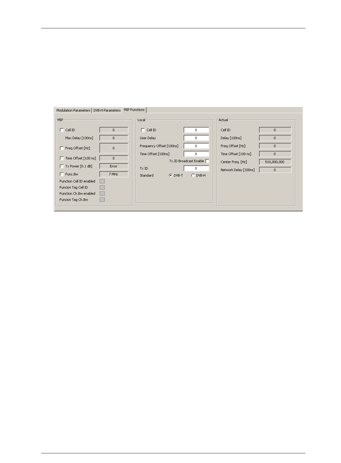
Screen Service SDT ARK 1 ECHO Operations
Jan, 2012 v 1.ATSC_FCC Page 3 - 45
3.4.10 MIP functions
These commands and indicators allow the enabling and monitoring of MIP functions
in SFN configuration, the setting of local functions and the monitoring of the actual
functions used by modulator.
Figure 13. MIP functions

Screen Service SDT ARK 1 ECHO Operations
Jan, 2012 v 1.ATSC_FCC Page 3 - 46
Table 11.
MIP function Modulation window: MIP functions
Box
Parameter /
Control
Description
Admitted Ranges / Values
R/H
MIP
Cell Id enable
MIP cell ID function enabling
Checked: Enabled
Not checked: Disabled
R
Local
General Cell Id enabling. Must be enabled to insert Cell Id into output TPS.
R
MIP
Cell ID
MIP cell ID monitoring.
R
Local
Local Cell ID setting.
Min: 0
Max: 65,535
R
Actual
Used Cell ID monitoring.
R
MIP
Max Delay
[100ns]
MIP max delay function monitoring
Min: 0
Max: 9,999,999
R
Local
User delay setting.
R
Actual
Used delay monitoring.
R
MIP
Freq. Offset
[Hz]
MIP frequency offset function enabling and monitoring
Checked: Enabled
Not checked: Disabled
R

Screen Service SDT ARK 1 ECHO Operations
Jan, 2012 v 1.ATSC_FCC Page 3 - 47
Box
Parameter /
Control
Description
Admitted Ranges / Values
R/H
Local
User frequency offset setting.
Min: -500,000 Hz
Max: 500,000 Hz
R
Actual
Used frequency offset monitoring.
R
MIP
Time Offset
[100ns]
MIP time offset function enabling and monitoring
Checked: Enabled
Not checked: Disabled
R
Local
User time offset setting.
Min: -32,768
Max: 32,767
R
Actual
Used time offset monitoring.
R
MIP
Tx Power
[0.1dB]
NOT IMPLEMENTED (MIP Tx power function enabling and monitoring).
Checked: Enabled
Not checked: Disabled
R

Screen Service SDT ARK 1 ECHO Operations
Jan, 2012 v 1.ATSC_FCC Page 3 - 48
Box
Parameter /
Control
Description
Admitted Ranges / Values
R/H
MIP
Func.Bw
NOT IMPLEMENTED (Function Bw enabling and monitoring).
Checked: Enabled
Not checked: Disabled
R
MIP
Function Cell
ID enabled
MIP Cell ID function enabling status.
Green: enabled
Grey: disabled
R
MIP
Function Tag
Cell ID.
Cell ID Tag detection.
Green: present
Grey: not present
R
MIP
Function
Ch.Bw enabled
MIP channel bandwidth function enabling status.
Green: enabled
Grey: disabled
R
MIP
Function Tag
Ch.Bw
Cannel bandwidth Tag detection.
Green: present
Grey: not present
R

Screen Service SDT ARK 1 ECHO Operations
Jan, 2012 v 1.ATSC_FCC Page 3 - 49
Box
Parameter /
Control
Description
Admitted Ranges / Values
R/H
Local
Tx ID
Broadcast
Enable
Tx ID 0 enabling.
Checked: Enabled
Not checked: Disabled
R
Local
Tx ID
User Tx ID setting.
Min: 0
Max: 65,535
R
Local
Standard
User transmission standard setting.
ATSC
o Checked: Enabled
o Not checked: Disabled
ATSC
o Checked: Enabled
o Not checked: Disabled
R
Actual
Center Freq.
[Hz]
Used center frequency indicator.
R

Screen Service SDT ARK 1 ECHO Operations
Jan, 2012 v 1.ATSC_FCC Page 3 - 50
Box
Parameter /
Control
Description
Admitted Ranges / Values
R/H
Actual
Network Delay
[100ns]
Used network delay indicator.
R
Table 12.
s
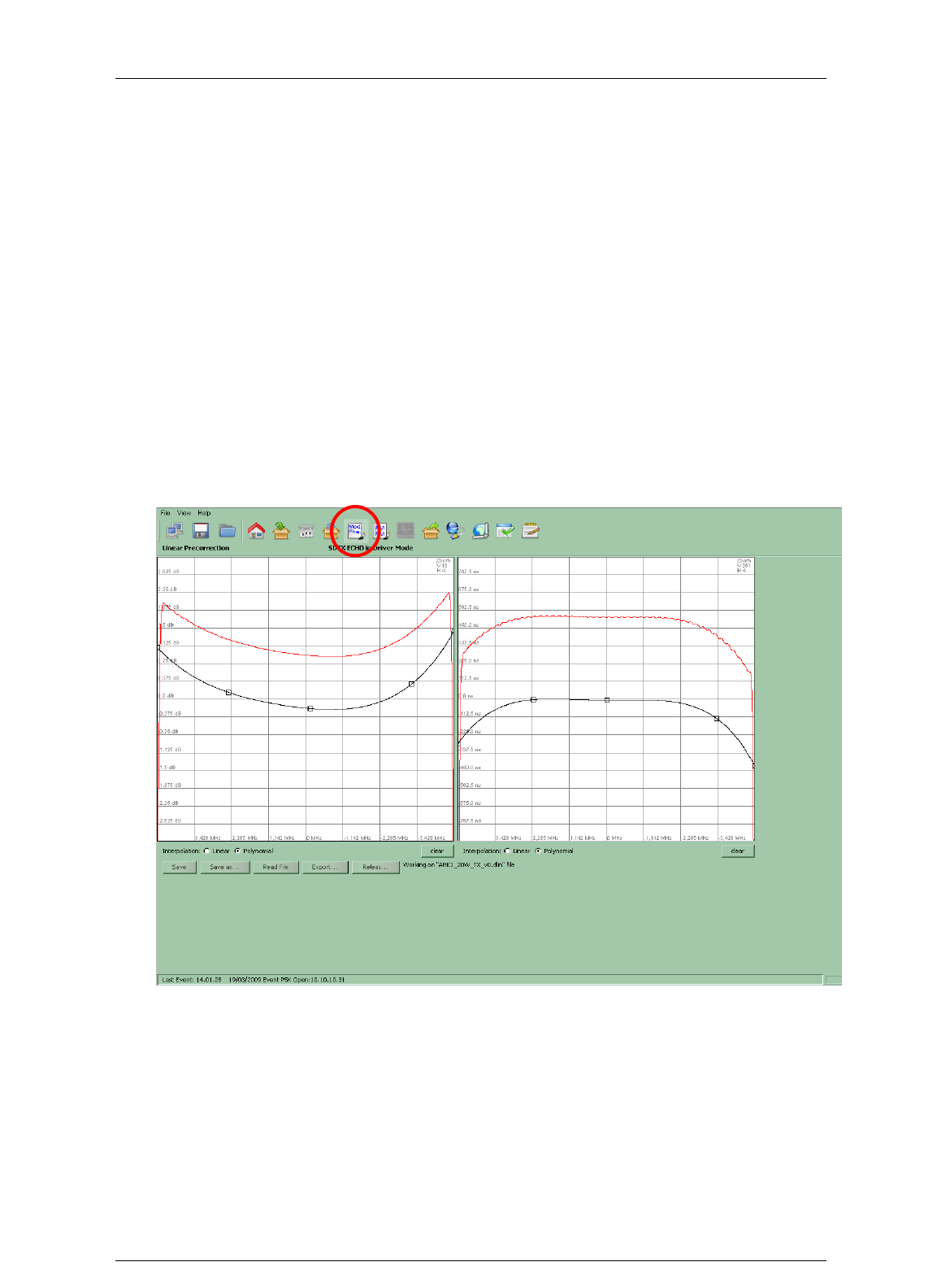
Screen Service SDT ARK 1 ECHO Operations
Jan, 2012 v 1.ATSC_FCC Page 3 - 51
3.5 PRE-CORRECTION TOOL
The ARK1 system provides a pre-correction tool for both Module&Phase and AM/PM output
signal pre-correction.
Remember to save curves changing before closing the connection to port 5000. At every
working session open
Note: the operation of uploading and downloading pre-correction curves moves a large
amount of data from and to the device. The use of these tools over low badwidth, not stable
or high distances netwoks could cause frequently time-out disconnections and it is not
reccommended.
3.5.1 Module&Phase
Click on MOD. PHA. button icon, highlighted in the nex figure, to modify the complex filter
curves for linear pre-correction.
Figure 14. Phase and module window

Screen Service SDT ARK 1 ECHO Operations
Jan, 2012 v 1.ATSC_FCC Page 3 - 52
This tool provides two grids for the drawing of:
Module of the filter’s curve.
Group Delay of the filter’s curve.
The two curves are used to calculate the linear pre-correction coefficients. The curves are
drawn by the interpolation of 1024 points referring to the points inserted and using a linear or
polynomial interpolation algorithm.
Knob points can be added with a left-click of the mouse on the grid and deleted with a right-
click, drag and move a point to change the curve.
Each coefficient variation, due to curves change, is saved in the FPGA “runtime” memory
registers and dynamically changes the device’s output.
The tool is prevented to send an “overflowing” amount of data to the device: curve changes
will be applied only when the mouse button is released.
In the module grid, the red curve is used to monitor the current module curve calculating and
saving. The last saved coefficients are locally downloaded from the FPGA runtime memory
registers in order to redraw the curve.
Click two times the right mouse button on the grid to open the zoom menu. The “H” options
are used to horizontally zoom (x01,x02,x04,x08,x16). The “V” options are used to vertically
zoom (x01,x02,x04).
During the saving actions are created two nonlinear pre-correction files:
*.dlin files: files containing digital coefficients values for Digital-IF linear pre-
correction curves.
*.alin files: files containing analog coefficients values for ATSC Re-modulator linear
pre-correction curves.
The following buttons allow the management of linear pre-correction files and the
management of the connection to port 5000:
Save: used to save in the device memory the current curves setting. The previously
saved file will be overwritten except in the evet that no files have been saved before;
in this case a dedicated window appears in order to let the user name the new file.
Save as: used to save in the device memory the current curves setting. The
previously saved file will be overwritten with a new name. in the evet that no files
have been saved before, a new file will be created.
Read file: used to reload the last saved file.
Export: used to download pre-correction files on the user PC. A browser window
allows the selection of the saving path.
Release: release the connection in order to allow others remote machines to
connect to port 5000 (refer to Connection to port 5000 paragraph).
Files are separately managed in analog and in digital AGC mode.
3.5.2 AM/PM
Click on AM/PM button icon, highlighted in the nex figure, to access the pre-correction
window.
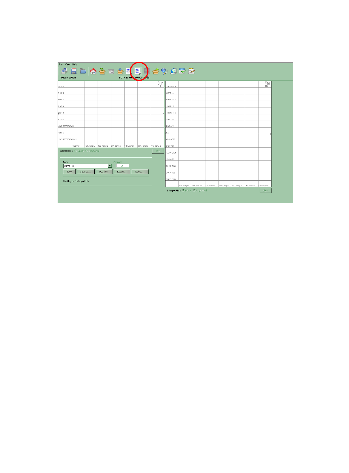
Screen Service SDT ARK 1 ECHO Operations
Jan, 2012 v 1.ATSC_FCC Page 3 - 53
Figure 15. AM/PM window
Two main actions are possible in this section:
AM/AM and AM/PM curve drawing: used to change the AM/PM pre-correction
coefficient.
AM/PM pre-correction files management: used to open or save AM/PM pre-
correction setting file.
AM/AM and AM/PM curves are specific for each power range of each output channel.
The two curves are used to calculate the AM/PM pre-correction coefficients. The curves are
drawn by the interpolation of 1024 points referring to the points inserted and using a linear or
polynomial interpolation algorithm.
Knob points can be added with a left-click of the mouse on the grid and deleted with a right-
click, drag and move a point to change the curve.
Each coefficient variation, due to curves change, is saved in the FPGA “runtime” memory
registers and dynamically changes the device’s output.
The tool is prevented to send an “overflowing” amount of data to the device: curve changes
will be applied only when the mouse button is released.
In the module grid, the red curve is used to monitor the current module curve calculating and
saving. The last saved coefficients are locally downloaded from the FPGA runtime memory
registers in order to redraw the curve.
Click two times the right mouse button on the grid to open the zoom menu. The “H” options
are used to horizontally zoom (x01,x02,x04,x08,x16). The “V” options are used to vertically
zoom (x01,x02,x04).
During saving actions are created two nonlinear pre-correction files:
*.dpre files: files containing digital coefficients values.
*.apre files: files containing analog coefficients values.

Screen Service SDT ARK 1 ECHO Operations
Jan, 2012 v 1.ATSC_FCC Page 3 - 54
The following buttons allow the management of linear pre-correction files and the
management of the connection to port 5000:
Save: used to save in the device memory the current curves setting. The previously
saved file will be overwritten except in the evet that no files have been saved before;
in this case a dedicated window appears in order to let the user name the new file.
Save as: used to save in the device memory the current curves setting. The
previously saved file will be overwritten with a new name. in the evet that no files
have been saved before, a new file will be created.
Read file: used to reload the last saved file.
Export: used to download pre-correction files on the user PC. A browser window
allows the selection of the saving path.
Release: release the connection in order to allow others remote machines to
connect to port 5000 (refer to Connection to port 5000 paragraph).
Files are separately managed in analog and in digital AGC mode.
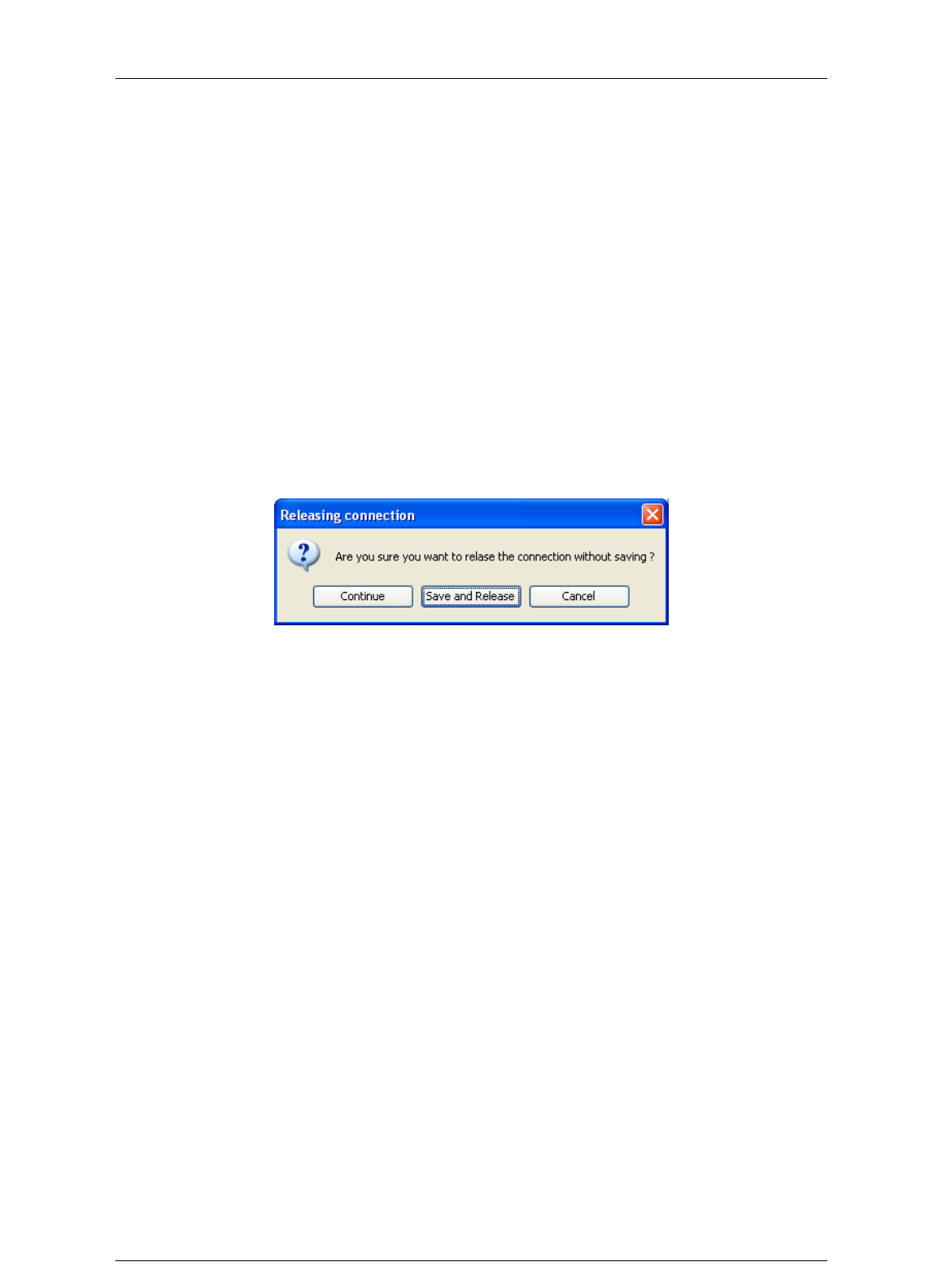
Screen Service SDT ARK 1 ECHO Operations
Jan, 2012 v 1.ATSC_FCC Page 3 - 55
3.5.3 Connection to port 5000
The connection to port 5000 is performed every time a pre-correction tool is opened through
Mod.Pha. button and AM/PM button, from Java interface,. The pre-correction tool opens and
keeps busy the connection to port 5000 till the connection releasing
The connection to this port precludes the possibility of:
programming the device;
allowing more than one user, the very same one that is keeping busy the connection,
to open the pre-correction tools.
The Release button comes through these limits. It closes the connection to port 5000, close
the Mod.Pha. / AM/PM window and opens the General window. Once clicked the Release
buttons and before quitting the pre-correction tool, three options are provided:
Continue: continue without saving;
Save and Release: save and continue;
Cancel: cancel the request of releasing the connection.
Figure 16. Realising connection
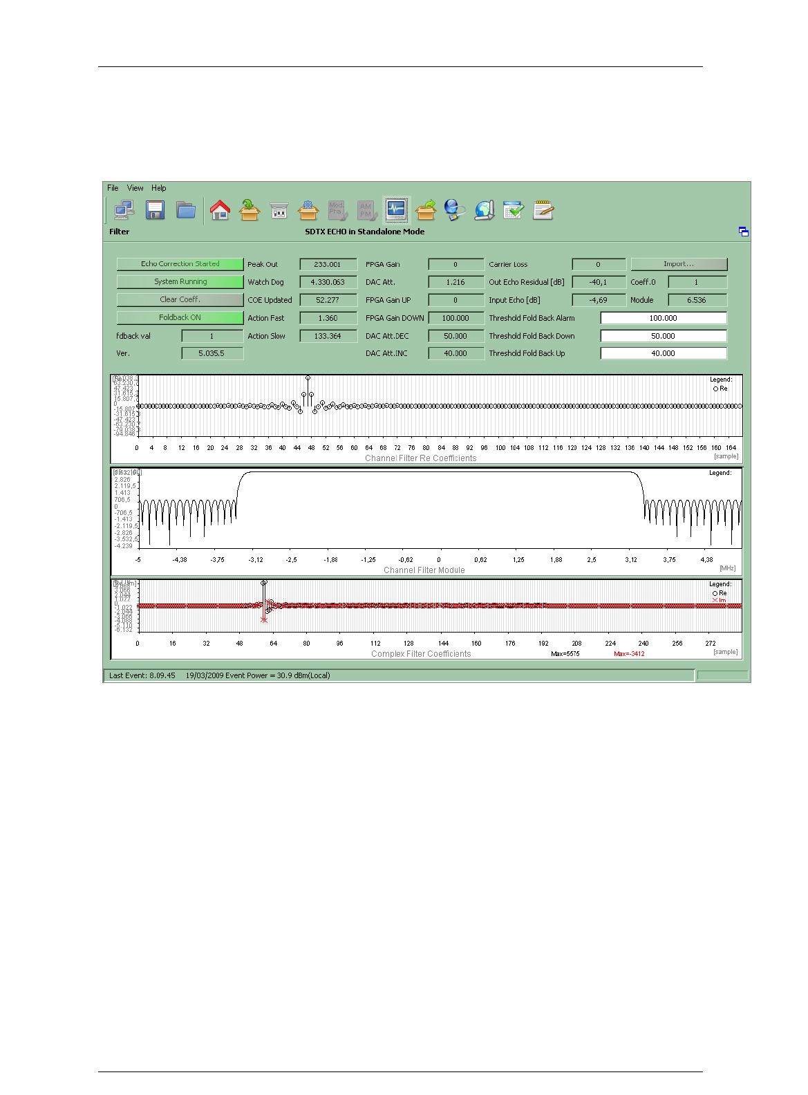
Screen Service SDT ARK 1 ECHO Operations
Jan, 2012 v 1.ATSC_FCC Page 3 - 56
3.6 Channel filter & complex filter
Click on Filter button icon, highlighted in the nex figure, to access the channel and complex filters
window.
Figure 17. Channel filter & complex filter window
Use the Filter window to manage and monitor channel and complex filters.
To understand the behavior of the Echo’s Channel Filter, a brief explanation is needed. The
Fold-back mode is an algorithm that makes use of 3 thresholds, determined by the
characteristics of the system (receiver and transmitter’s antenna front and back gains), to
calculate the optimal range of the transmitter’s output RF power that results in controlled
echo level on the receiver side antenna. The so introduced thresholds are:
Threshold Fold Back Alarm: individuates the level of the transmitter’s output RF
power that determines an uncontrollable echo level on the receiver side antenna.
Threshold Fold Back Down: individuates the upper limit of the optimal range of the
transmitter’s output RF power. When the “Module” value is higher than this
threshold, the controller decreases the output RF power.
Threshold Fold Back Up: individuates the lower limit of the optimal range of the
transmitter’s output RF power. When the “Module” value is lower than this threshold,
the controller increases the output RF power.

Screen Service SDT ARK 1 ECHO Operations
Jan, 2012 v 1.ATSC_FCC Page 3 - 57
It follows that:
Thr. FB Alarm > Thr. FB Down > Thr. FB Up.
The “FPGA Gain” value results from the comparison of the “Module” value with the
thresholds:
0: when “Module” is lower than FB Up.
1: when “Module is higher than FB Down.
2: when “Module” is comprised between FB Up and FB Down.
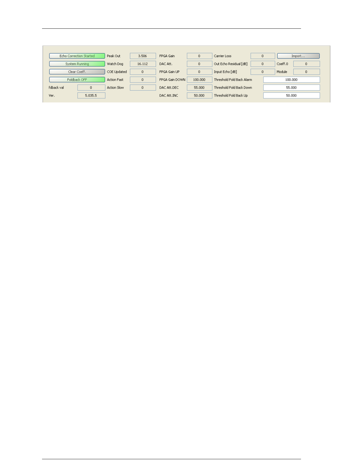
Screen Service SDT ARK 1 ECHO Operations
Jan, 2012 v 1.ATSC_FCC Page 3 - 58
Figure 18. Filters commands and monitors

Screen Service SDT ARK 1 ECHO Operations
Jan, 2012 v 1.ATSC_FCC Page 3 - 59
Box
Parameter /
Control
Description
Admitted Ranges /
Values
R/H/E
General
Echo Correction
Started/Stopped
Enables or disables the updating of the
coefficients. When in “Echo Correction Started”
mode, the system continues calculating the
coefficients, but those are not updated.
Red: Echo
Correction
Stopped
Green:
Echo
Correction
Started.
R
General
System
Running/Locked
Indicates the running status of the echo canceling
process.
General
Clear Coeff.
Resets the complex filter coefficients
General
Foldback
ON/OFF
Enables or disables the Foldback mode.
Fold Back
ON
Fold Back
OFF
General
Fdback val
Indicates whether the Foldback mode is active („1‟
is shown) or not („0‟ is shown).
0: Fold-
back not
active.
1: Fold-
back active
General
Ver.
Indicates an error code associated with the cause
that determined the correction action tha was
taken. Introduced for debug purposes.
General
Peak Out
Indicates the peak of the module of the signal at
the output of the Channel Filter.
General
Watch Dog
Indicates the value of the counter, incremented at
each Echo control loop iteration. Introduced for
debug purposes.
General
COE Updated
Indicates the value of the counter, incremented
each time the coefficients are updated. Introduced
for debug purposes.

Screen Service SDT ARK 1 ECHO Operations
Jan, 2012 v 1.ATSC_FCC Page 3 - 60
General
Action Fast
Indicates the value of the counter, incremented
each time an Action Fast was performed.
Introduced for debug purposes.
General
Action Slow
Indicates the value of the counter, incremented
each time an Action Slow was performed.
Introduced for debug purposes.
General
FPGA Gain
Indicates the actual value of the Foldback status.
Introduced for debug purposes.
0: when
“Module” is
lower than
Thr. FB
Up.
1: when
“Module” is
higher than
Thr. FB
Down.
2: when
“Module” is
comprised
between
Thr. FB Up
and Thr.
FB Down
(Optimal
range).
General
DAC Att.
Indicates the value of the PWM control. Introduced
for debug purposes.
General
FPGA Gain UP
It is an internal counter introduced for debug
purposes.
General
FPGA Gain
DOWN
Shows the same value as “Threshold Fold Back
Alarm”. Introduced for debug purposes.
General
DAC Att. DEC
Shows the same value as “Threshold Fold Back
Down”. Introduced for debug purposes.
General
DAC Att. INC
Shows the same value as “Threshold Fold Back
Up”. Introduced for debug purposes.
General
Carrier Loss
It is an internal counter introduced for debug
purposes.

Screen Service SDT ARK 1 ECHO Operations
Jan, 2012 v 1.ATSC_FCC Page 3 - 61
General
Out Echo
Residual [dB]
Indicates the value of the Echo amplitude that was
not compensated.
General
Input Echo [dB]
Indicates the value of the Echo amplitude that was
compensated.
General
Import…
Imports the “.echf” file that contains the channel
filter coefficients.
R
General
Coeff.0
Shows the same value as “fdback val” indicator.
Introduced for debug purposes.
R
General
Module
Shows the peak value of the module of the current
filter‟s coefficients.
Min: -
214748364
8
Max:
214748364
7
General
Threshold Fold
Back Alarm
Specifies the peak value of the module of the
current filter‟s coefficients. to be considered as
alarm level. The output RF power shall always be
lower than this threshold.
Min: -
214748364
8
Max:
214748364
7
R
General
Threshold Fold
Back Down
Specifies the peak value of the module of the
current filter‟s coefficients. to be considered as
higher level of the optimal range. The optimal
range is determined by the “Threshold Fold Back
Down” and “Threshold Fold Back Up” values.
Min: -
214748364
8
Max:
214748364
7
R

Screen Service SDT ARK 1 ECHO Operations
Jan, 2012 v 1.ATSC_FCC Page 3 - 62
General
Threshold Fold
Back Up
Specifies the peak value of the module of the
current filter‟s coefficients. to be considered as
lower level of the optimal range. The optimal range
is determined by the “Threshold Fold Back Down”
and “Threshold Fold Back Up” values.
Min: -
214748364
8
Max:
214748364
7
General
Channel Filter
Re Coefficients
Shows, in a graph, the actual impulse response of
the Channel Filter (the inverse Fourier Transform
of the transfer function).
General
Channel Filter
Module
Shows, in a graph, the actual frequency transfer
function of the Channel Filter.
General
Complex Filter
Coefficients
Shows, in a graph, the actual complex coefficients,
plotting separately the real (black dots) and
imaginary (red crosses) parts.
3.6.1 OUTPUT
Click on Output button icon, highlighted in the nex figure, to access the output window.
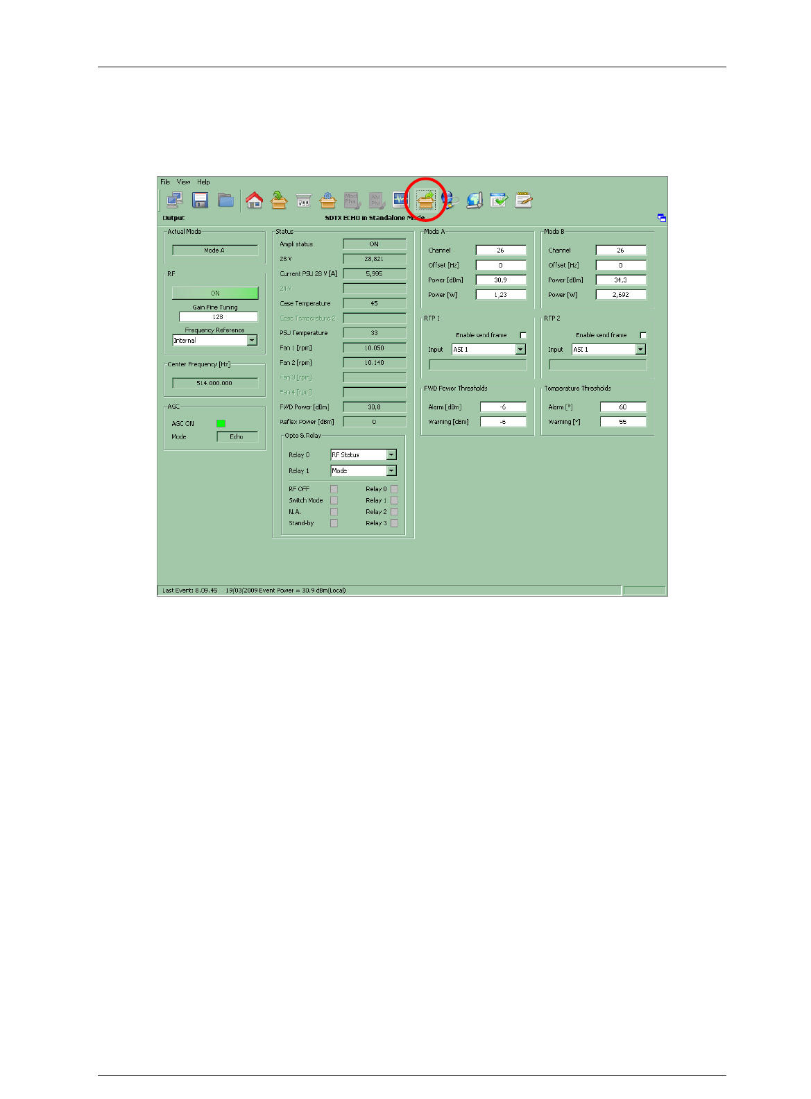
Screen Service SDT ARK 1 ECHO Operations
Jan, 2012 v 1.ATSC_FCC Page 3 - 63
Figure 19. Output window
Use the Output window to change and monitor both Ethernet and RF output settings, and to
monitor all accessible hardware indicators.

Screen Service SDT ARK 1 ECHO Operations
Jan, 2012 v 1.ATSC_FCC Page 3 - 64
Output window
Box
Parameter / Control
Description
Admitted Ranges / Values
R/H
RF
ON / OFF
Output RF signal enabling. The possible output RF signal status are the following:
ON;
RF not On: automatic switch off of the output signal (refer to Ampli status);
OFF: manual switch off of the output signal.
Green: ON
Green: RF not ON
Red: OFF
R/H
RF
Frequency reference
Frequency reference source selector.
External
Internal
GPS
R/H
RF
Internal Freq. Ref. Tune
Internal frequency reference fine tuning setting. Allows the fine tuning of VCO, internal clock
oscillator, with 60 Hz steps.
Min: 0
Max: 255
R/H
AGC
AGC ON
AGC status.
Green: ON
Grey: OFF
R/H

Screen Service SDT ARK 1 ECHO Operations
Jan, 2012 v 1.ATSC_FCC Page 3 - 65
Box
Parameter / Control
Description
Admitted Ranges / Values
R/H
AGC
Mode
Current AGC mode indicator.
Analog/Digital:
o Green: ON
o Grey: OFF
R/H
Frequency
Out [Hz]
Frequency
Out [Hz]
Output center frequency expressed in Hz.
Status
Ampli status
Current amplifier status indicator.
On
Off
Restart
Stand-by off
Init
Alarm off
Rf off
Opto off
R/H
Status
28V
PSU 28V indicator (values are expressed in V).
R/H
Status
Current PSU 28V [A]
PSU 28V current indicator (values are expressed in A).
R/H

Screen Service SDT ARK 1 ECHO Operations
Jan, 2012 v 1.ATSC_FCC Page 3 - 66
Box
Parameter / Control
Description
Admitted Ranges / Values
R/H
Status
28V / 42V
PSU voltage indicator (values are expressed in V). It depends on the hardware type
of the device:
28V for SDTx_Echo 20W and 50W;
42V for SDTx_Echo 200W.
R/H
Status
Case Temperature
Case temperature indicator (values are expressed in °C).
R/H
Status
Case Temperature 2
2nd Case temperature indicator (values are expressed in °C).
Only in SDTX 200 version.
Status
PSU Temperature
PSU temperature indicator (values are expressed in °C).
R/H
Status
Fan 1
Fan 1 speed indicator (values are expressed in rpm).
R/H
Status
Fan 2
Fan 2 speed indicator (values are expressed in rpm).
R/H
Status
Fan 3
Fan 3 speed indicator (values are expressed in rpm).
Only in SDTX 200 version.
R/H
Status
Fan 4
Fan 4 speed indicator (values are expressed in rpm).
Only in SDTX 200 version.
R/H
Status
FWD Power [dBm]
Output forward power indicator (values are expressed in dBm).
R/H
Status
Reflex Power [dBm]
Output reflex power indicator (values are expressed in dBm).
R/H
Opto & Relay
Relay 0
Selector of Relay 0 mode.
Alarm: indicator of an alarm condition
Mode: indicator of operating mode
R/H

Screen Service SDT ARK 1 ECHO Operations
Jan, 2012 v 1.ATSC_FCC Page 3 - 67
Box
Parameter / Control
Description
Admitted Ranges / Values
R/H
Opto & Relay
Relay 0…3
Relays status indicators.
Green: Alarm on/Mode A
Grey: Alarm off/Mode B
R/H
Opto&Relay
Opto 0…3
Opto status indicators. Optos are normally opened:
Opto 0: RF Off, manual switching off of output RF;
Opto 1: Mode A/B switch;
Opto 2: Retry of amplifier alarms (only in SDTX 200 version);
Opto 3: Stand-by enabling; it puts the device on stand-by.
Green: Closed (0)
Grey: Opened (1)
R/H
Mode A / Mode B
Channel
Output channel.
Min: 21
Max: 69
R/H
Mode A / Mode B
Power [dBm]
Output power (expressed in dBm).
Analog min: 23 dBm
Analog max: 43 dBm
Digital min: 17 dBm
Digital max: 37 dBm
R/H
Mode A / Mode B
Power [W]
Output power (expressed in W).
R/H

Screen Service SDT ARK 1 ECHO Operations
Jan, 2012 v 1.ATSC_FCC Page 3 - 68
Box
Parameter / Control
Description
Admitted Ranges / Values
R/H
Mode A / Mode B
Offset [Hz]
Output frequency offset (expressed in Hz).
Min: -4 MHz
Max: 4 MHz
R/H
FWD Power Thresholds
Warning [dB]
Forward power warning threshold expressed in dBm.
Min: -16 dBm
Max: 0 dBm
R/H
FWD Power Thresholds
Alarm [dB]
Forward power alarm threshold expressed in dBm.
R/H
Temperature Thresholds
Warning
Case temperature warning threshold expressed in °C.
Min: 0 °C
Max: 100 °C
R/H
Temperature Thresholds
Alarm
Case temperature alarm threshold expressed in °C.
R/H
RTP 1 / RTP 2
Enable send frame
Channel 1/2 Ethernet transmission enabling.
Enabled
Disabled
R/H

Screen Service SDT ARK 1 ECHO Operations
Jan, 2012 v 1.ATSC_FCC Page 3 - 69
Box
Parameter / Control
Description
Admitted Ranges / Values
R/H
RTP 1 / RTP 2
Input
Input to output Ethernet channel 1/2 selector.
ASI 0
ASI 1
ASI 2
ASI 3
RX.HP
RX.LP
GbE1
GbE2
R/H
RTP 1 / RTP 2
ON/OFF
Ethernet transmission on channel 1/2 status indicator.
ON
OFF
R/H
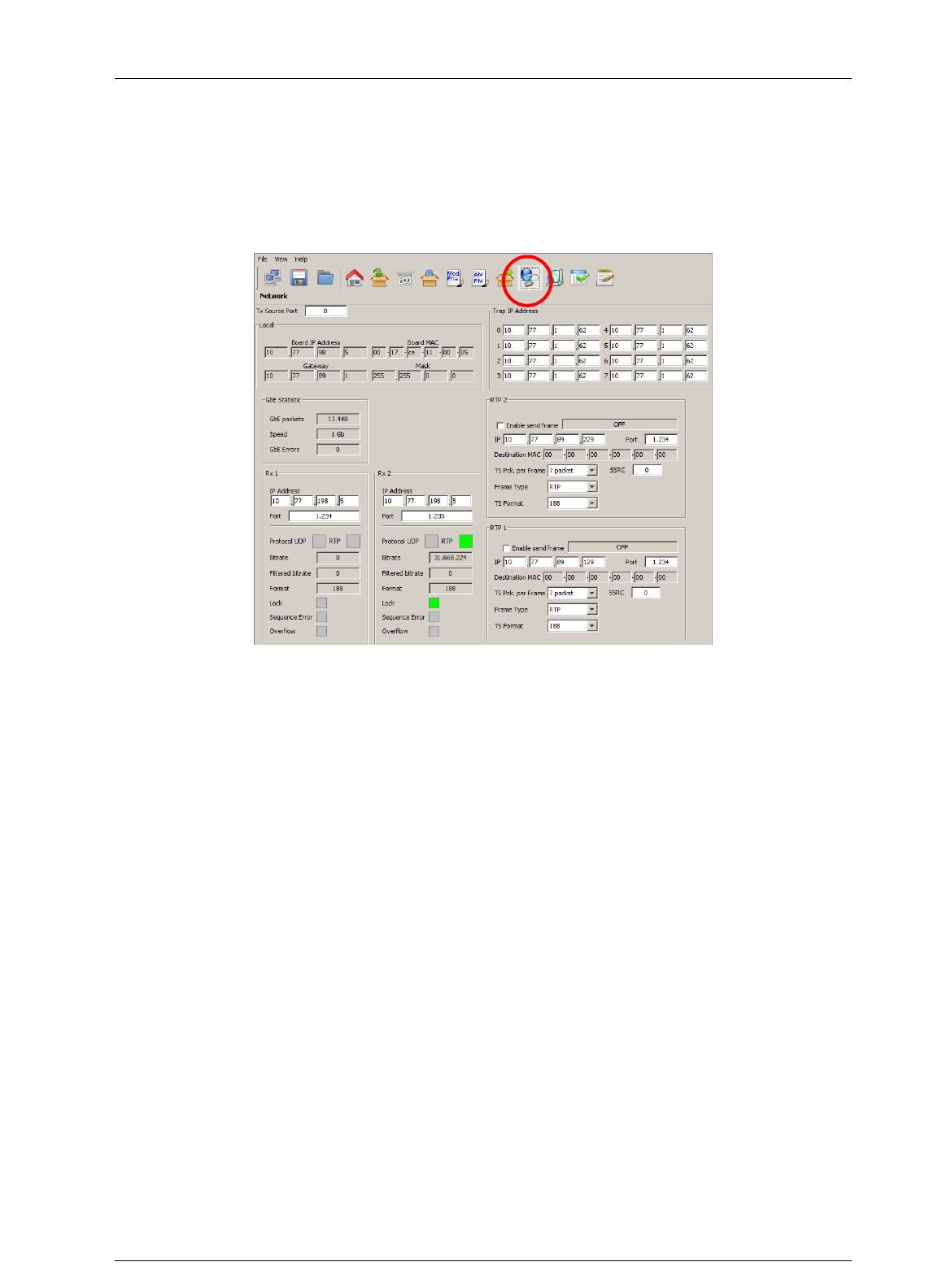
Screen Service SDT ARK 1 ECHO Operations
Jan, 2012 v 1.ATSC_FCC Page 3 - 70
3.7 NETWORK
Click on Network button icon, highlighted in the nex figure, to access the Network management
window.
Figure 20. Network window
This window allows the Network management on both PRO-MPEG COP 3 RX and TX sides. It
also allows the monitoring of the board IP and MAC addresses.
Note: The Clock Recovery Function, used in MFN transmissions of received streams on
Ethernet channels 1 and/or 2, is based on the timestamps of incoming packets. UDP packets do
not contain STS information therefore it is not allowed using GbE inputs with UDP protocol in
MFN transmission mode.

Screen Service SDT ARK 1 ECHO Operations
Jan, 2012 v 1.ATSC_FCC Page 3 - 71
Table 13. Network window
Box
Parameter/
Control
Description
Admitted Ranges / Values
R/H
Local
Board IP
address
Board IP address.
R/H
Local
Board MAC
address
Board MAC address.
R/H
Local
Gateway
Gateway address.
R/H
Local
Mask
Net Mask.
R/H
Local
Tx Source
Port
Board receiving port.
Min: 0
Max: 65,535
R/H
Trap IP address
0…7
Trap 0…7 destination IP address.
R/H
Rx 1 / Rx 2
IP Address
Channel 1/2 receiving IP address.
R
Rx 1 / Rx 2
Port
Channel 1/2 receiving port.
Min: 0
Max: 65,535
R
Rx 1 / Rx 2
Protocol
Ethernet input packets protocol.
UDP
RTP
R
Rx 1 / Rx 2
Bitrate [bit/s]
Bitrate of TS from Ethernet input.
R

Screen Service SDT ARK 1 ECHO Operations
Jan, 2012 v 1.ATSC_FCC Page 3 - 72
Box
Parameter/
Control
Description
Admitted Ranges / Values
R/H
Rx 1 / Rx 2
Filtered
bitrate[bit/s]
Bitrate actually used by the modulator.
Zero when the input is not
selected
Equal to the total bitrate, when
Delete Null Packets disabled
Less than total bitrate, when
Delete Null Packets enabled
R
Rx 1 / Rx 2
Format
Received transmission format.
188 Bytes
240 Bytes
R
Rx 1 / Rx 2
Lock
Ethernet input lock status indicator. The input Transport Stream is locked when no more than two
consecutive Sync Byte are missed.
Green: Lock
Grey: Not locked
R
Rx 1 / Rx 2
Sequence
error
Ethernet input Sequence error alarm status indicator.
This alarm condition occurs when a sequence error occurs
Red: Error
Grey: No errors
R
Rx 1 / Rx 2
Overflow
Input GbE overflow alarm status. This alarm condition occurs when the input bitrate exceeds the
capability of the modulation (Ref. to ETSI EN 300 744).
Red: Alarm on
Grey: Alarm off
R
Gbe statistic
GBE
Packets
Total amount of good frames received.
R/H

Screen Service SDT ARK 1 ECHO Operations
Jan, 2012 v 1.ATSC_FCC Page 3 - 73
Box
Parameter/
Control
Description
Admitted Ranges / Values
R/H
Gbe statistic
Speed
Ethernet speed.
10 Mbit//s
100 Mbit//s
1 Gbit/s
R/H
Gbe statistic
GBE Errors
Total amount of bad frames received.
R/H
Community
Get
Read community setting.
R/H
Community
Set
Set community setting.
R/H
Community
Trap
Trap community setting.
R/H
RTP 1/ RTP 2
Enable send
frame
Channel 1/2 Ethernet transmission enabling.
Enabled
Disabled
R
RTP 1/ RTP 2
IP
Channel 1/2 Ethernet transmission IP address.
R
RTP 1/ RTP 2
Port
Port used for RTP/UDP data transmission
Min: 0
Max: 65,535
R
RTP 1/ RTP 2
ON/OFF
Ethernet transmission on channel 1/2 status indicator.
ON
OFF
R
RTP 1/ RTP 2
Destination
MAC
Destination MAC address.
R
RTP 1/ RTP 2
SSRC
SSRC identifier of the RTP transmission on channel ½.
R

Screen Service SDT ARK 1 ECHO Operations
Jan, 2012 v 1.ATSC_FCC Page 3 - 74
Box
Parameter/
Control
Description
Admitted Ranges / Values
R/H
RTP 1/ RTP 2
TS Pck per
Frame
Number of packets per frame.
Min: 1
Max: 7
R
RTP 1/ RTP 2
Frame type
Transmission protocol selector.
RTP
UDP
R
RTP 1/ RTP 2
TS Format
Transmission format.
188 Bytes
240 Bytes
R
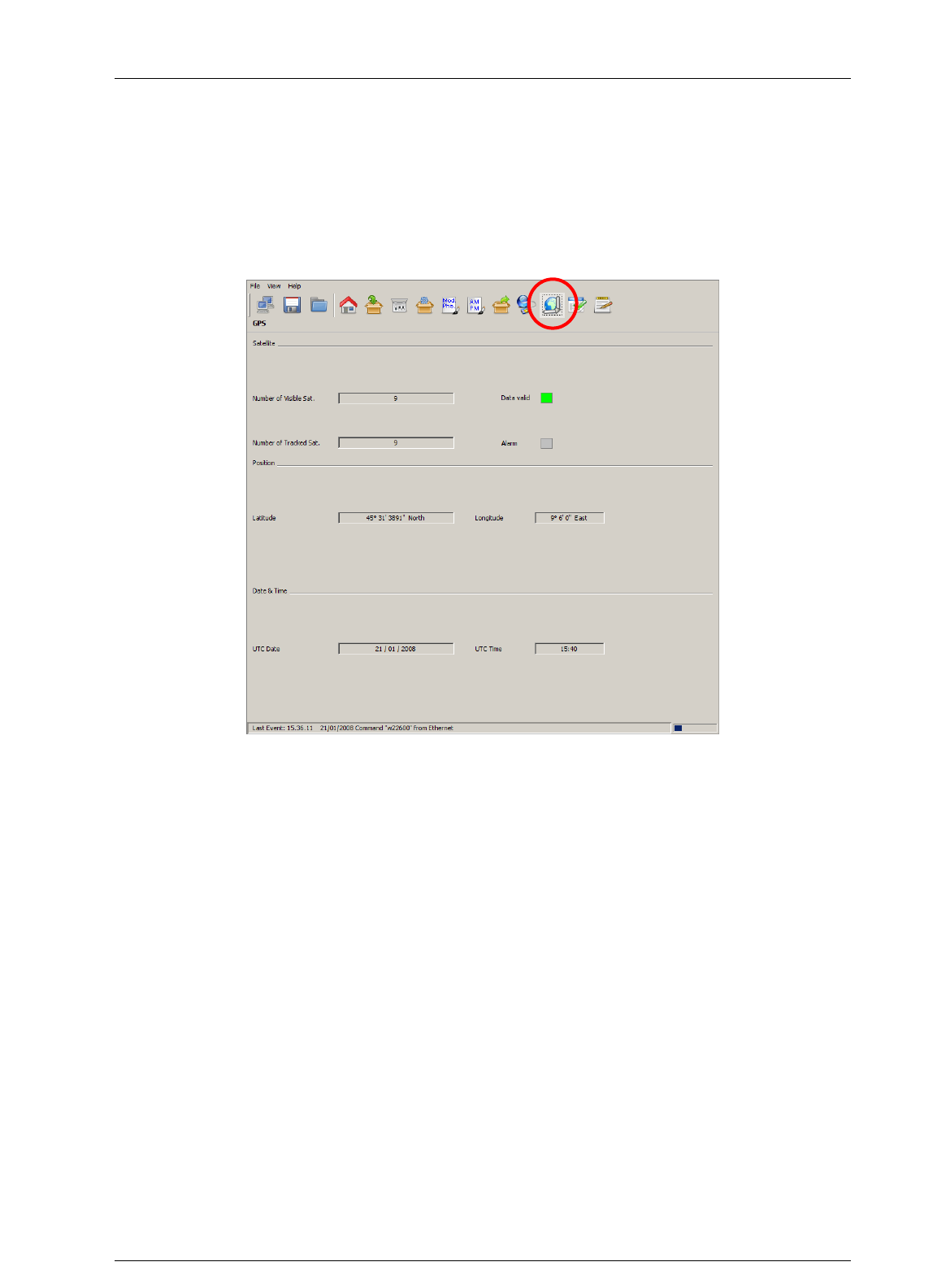
Screen Service SDT ARK 1 ECHO Operations
Jan, 2012 v 1.ATSC_FCC Page 3 - 75
3.8 GPS
Click on GPS button icon, highlighted in the next figure, to access the GPS received statistics
window.
Figure 21. GPS window

Screen Service SDT ARK 1 ECHO Operations
Jan, 2012 v 1.ATSC_FCC Page 3 - 76
Table 14.
GPS window
Box
Parameter/
Control
Description
Admitted Ranges / Values
R/H
Satellite
#Number of
Visible sat
Number of visible GPS satellites indicator.
R/H
Satellite
#Number of
Tracked sat
Number of tracked GPS satellites indicator.
R/H
Satellite
Alarm
GPS alarm status indicator. This alarm is a logic OR of the GPS alarms (refer to
Alarms
paragraph).
Red: Alarm on
Grey: Alarm off
R/H
Satellite
Data valid
Valid satellite signal receiving status indicator.
Green: Valid
Grey: Not valid
R/H
Position
Latitude(°)
Site latitude expressed in degrees.
R/H
Position
Longitude (°)
Site longitude expressed in degrees.
R/H
Date & Time
UTC Time
Current time indicator.
Each GPS satellite has an atomic clock and continually transmits messages containing the
current time and date at the start of the message sended by the GPS itself.
R/H
Date & Time
UTC Date
Current date indicator.
Each GPS satellite has an atomic clock and continually transmits messages containing the
current time and date at the start of the message sended by the GPS itself.
R/H
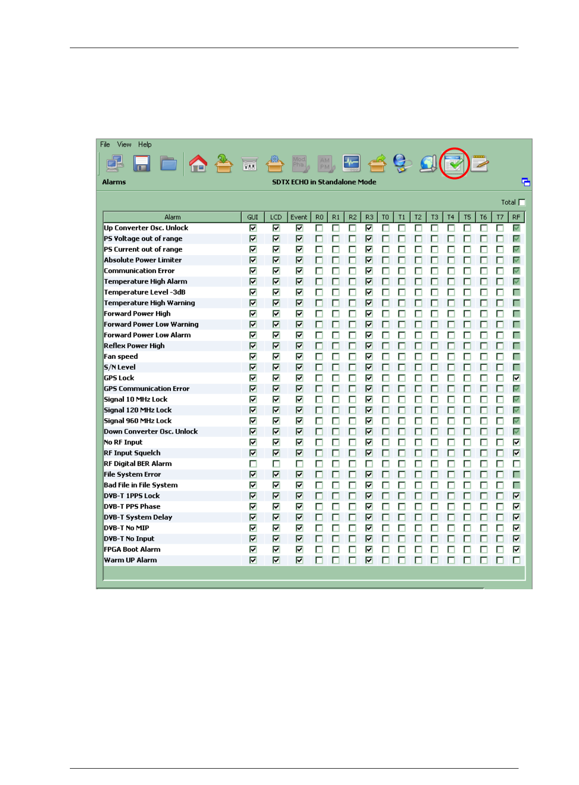
Screen Service SDT ARK 1 ECHO Operations
Jan, 2012 v 1.ATSC_FCC Page 3 - 77
3.9 ALARMS
Click on Alarms button icon, highlighted in the nex figure, to access the alarms management
window.
Figure 22. Alarms window

Screen Service SDT ARK 1 ECHO Operations
Jan, 2012 v 1.ATSC_FCC Page 3 - 78
The Alarm window allows the setting of alarm masks and the monitoring of alarms status.
Use alarm masks to select how and which alarm have to be notified.
Masks are organized in columns. The sixteen columns represent sixteen destinations of each
alarm condition:
GUI: the selected alarms status is notified on the Java alarm page icon.
LCD: the selected alarms status is notified on LCD display lighting the alarm button
and listing the alarms in the Alarms menu (refer to Alarms Menu paragraph).
Event: the selected alarms status generate an alarm event that will be logged in
the event memory (refer to Events paragraph).
R0…R3: the selected alarms switch on the corresponding relay.
T0…T7: the selected alarms generate the corresponding trap messages (refer to
Network paragraph to set destination IP addresses).
RF: the selected alarms switch off the RF output. The RF mask is almost entirely
fixed in order to avoid board damages or malfunctioning.
In the Alarms window, when an alarm condition occurs, the relative alarm is red highlighted.
The Total check box enables all alarms-to-masks associations.
Remember to enable the RF Off alarms mask of ATSC alarms while working in Tx ATSC mode.

Screen Service SDT ARK 1 ECHO Operations
Jan, 2012 v 1.ATSC_FCC Page 3 - 79
Table 15. Alarms window
Alarm
Description
H/R
(1)
Troubleshooting
RF
mask
(2)
Up converter Osc. Unlock
PLL of the Upconveter board not locked to 120 MHz clock.
H/R
Hardware fault
1
PS 28V out range
Voltage out of range. The range is 20V up to 30V.
H/R
Hardware fault
1
PS Current out of range
The current exceeds the 22 Ampere upper limit.
H/R
Hardware fault
1
Absolute Power Limiter
The output power exceeds the maximum endurable limit.
H/R
Hardware fault
1
Up converter communication error
Communication errors between ARK1 main board and
Up-converter board.
H/R
Hardware fault
1
Temperature High Alarm
Case temperature over 70°C, the maximum endurable
limit.
H/R
Check alarm and warning throesholds
Lower the output power to decrease internal temperature
Check the device airflow
Check fans
0
Temperature Level-3dB
Temperature level goes over the alarm threshold.
The output power is consequently lowered of 3 dBm.
H/R
0
Temperature High Warning
Temperature level goes over the warning threshold.
H/R
0
Forward Power High
FWD power goes over the maximum endurable limit.
H/R
Hardware fault
1
Forward Power Low Alarm
FWD power level goes over the alarm threshold.
H/R
Check alarm and warning thresholds
At every amplifier initialization the FWD power alarm and warning
are temporary on
Amplifier is not properly working, hardware fault
0
Forward Power Low Warning
FWD power level goes over the warning threshold.
H/R
0

Screen Service SDT ARK 1 ECHO Operations
Jan, 2012 v 1.ATSC_FCC Page 3 - 80
Reflex Power High
RFL power goes over the maximum endurable limit.
H/R
Check the RF output for disconnection or wrong impendence
adaptation
0
Fan Speed
Fans speed is under the minimum speed (1,000 rpm).
H/R
Check fans connections
Verify that fans are not damaged; in this case substitute them. The
substitution can be performed during device normal operations
0
S/N level
Signal to noise ratio under the S/N threshold:
Heterodyne Digital repeater: Signal to Noise ratio,
detected by the ATSC receiver, under the S/N
threshold
TX ATSC: Signal to Noise ratio, detected by the ATSC
receiver, under the S/N threshold. only when RX HP
and/or RX LP inputs are selected as input HP and/or
LP.
H/R
Check alarm threshold
Check input signal and input channel
0
GPS Lock
GPS signal is not lock.
H/R
Check cable and GPS antenna connections
Hardware fault
X
GPS Communication Error
Communication errors between ARK1 main board and
GPS board.
H/R
Hardware fault
1

Screen Service SDT ARK 1 ECHO Operations
Jan, 2012 v 1.ATSC_FCC Page 3 - 81
Signal 10 MHz Lock
10 MHz is not locked.
H/R
If the frequency reference is Internal: internal PLL fault
If the frequency reference is External:
o Internal PLL fault
o Lack of external 10 MHz
o Hardware faul
If the frequency reference is Internal:
o Check GPS alarms
o Internal PLL fault
o Hardware fault
1
Signal 120 MHz Lock
120 MHz is not locked.
H/R
In SFN configuration, when selected TS input or MIP are not
detected, 120 MHz oscillator can loose the lock
Hardware fault
1
Signal 960 MHz Lock
960 MHz is not locked.
H/R
Hardware fault
1
Down Converter Osc. Unlock
PLL of the Downconveter board not locked to 120 MHz
clock.
H/R
Hardware fault
1
No RF Input
Input RF missing.
H/R
Check input channel
Check RF input signal type, source and connector
X

Screen Service SDT ARK 1 ECHO Operations
Jan, 2012 v 1.ATSC_FCC Page 3 - 82
RF Input Squelch
Rx level under the Squelch threshold.
H/R
Check Squelch alarm threshold
Check input channel
Check RF input source and signal
X
RF Digital Ber. Alarm
Demodulator BER over the alarm threshold.
H/R
Check BER alarm threshold
Check RF input source and signal
X
File System Error
File System loading error.
H/R
File system partition damage
0
Bad File in File system
One more files missing in the File System.
H/R
Check files list
Reload the file system
0
1PPS Lock
1PPS is not lock to the selected frequency reference.
If the frequency reference is Internal: internal PLL fault
If the frequency reference is External:
o Internal PLL fault
o Lack of external 1PPS
o Hardware faul
If the frequency reference is Internal:
o Check GPS alarms
o Internal PLL fault
o Hardware fault
X

Screen Service SDT ARK 1 ECHO Operations
Jan, 2012 v 1.ATSC_FCC Page 3 - 83
PPS Phase
1PPS is not lock to a common reference of the network.
R
Check 1PPS
Hardware fault
X
System Delay
System delay is too high.
R
X
No MIP
MIP packets missing.
R
Check input signal
X
No Input
Input Transport Stream missing.
R
Check input statistics
X
FPGA Boot alarm
FPGA boot has not been successfully completed.
R
Restart the machine
Reload the file system
X
Warm up alarm
Temperature level under 5°C or temperature sensor fault.
H/R
Restart the machine
Temperature sensor fault
X
Notes to the table:
(1) H stands for Heterodyne Repeater and R stands for Re-broadcasting modulator.
(2) 0/1 stands for disabled/enabled and is fixed, X stands for not fixed.
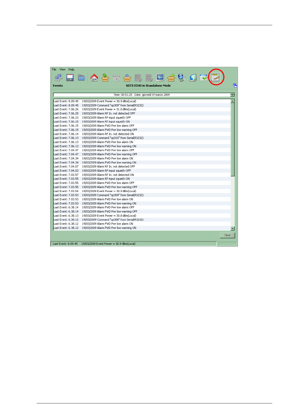
Screen Service SDT ARK 1 ECHO Operations
Jan, 2012 v 1.ATSC_FCC Page 3 - 84
3.10 EVENTS
Click on Events button icon, highlighted in the nex figure, to access the events windos.
Figure 23. Events window

Screen Service SDT ARK 1 ECHO Operations
Jan, 2012 v 1.ATSC_FCC Page 3 - 85
Open the Events window to slide the events list.
Events are reported with the following information:
Time: event detection time.
Date: event detection date.
Type: event type:
o Alarm (refer to alarms list in Alarms paragraph);
o Command (See ARK1_SW_Reference manual_v1_6.doc for further
information);
o Event (refer to Events list table);
o System init (refer to Init System Event paragraph);
o TASK_ERR (refer to Task Error Event paragraph).
Description: event description:
o Alarm: which alarm generated the event;
o Command: the low level code and command source;
o Event: event description;
o System Init: system initialization perhaps followed by the alarm
Use the following buttons, sited on the right side of the window, to manage the Events list:
Clear: resets the events list.
Get History: gets all the stored events from the last board reset (max 512 events).

Screen Service SDT ARK 1 ECHO Operations
Jan, 2012 v 1.ATSC_FCC Page 3 - 86
Table 16.
Events list
Event
Description
RF OFF enabled from OPTO
RF output switched off through OPTO 0.
RF OFF disabled from OPTO
RF output switched on through OPTO 0.
Stand-by ON from OPTO
Stand-by mode enabled through OPTO 3.
Stand-by OFF from OPTO
Stand-by mode disabled through OPTO 3.
Stand-by ON from LCD
Stand-by mode enabled through LCD button.
Stand-by OFF
Stand-by mode disabled through LCD button.
Power = xx.x dBm (source)
New output power setting.
xx.x: output power expressed in dBm.
Source: Local or MIP
Update file *.xxxx
New file loading.
Xxxx: file extension.
P5K open: xx.xx.xx.xx
Connection to port 5000 open.
xx.xx.xx.xx: host IP address.
P5K closed
Connection to port 5000 closed.
Mode X= (mode)
Manual change mode.
X: new mode (A/B)
mode: TX ATSC / Rep. Analog / Rep. Digital.
Switch mode swhitch X => Y
Switch mode change.
Switch mode: Manual / Auto / Opto / Time.
X=>Y: A/B=>B/A.
UPCV not configured
The Upconverter has been found not configured during the
UPCV_TASK (refer to
Task Error Event
paragraph).
UPCV configured
Automatic reconfiguring of the Upconverter. It automatically starts at
every UPCV not configured event or UPCV communication error.
File system busy
File system already in use while tring to employ it (e.g. change mode
during a file loading).
UTC Time set from GPS
Time and date set by GPS. As soon as the GPS lock is regained,
once lost, and if the current time and date are different from the GPS
ones, the UTC time is set by GPS.
Warm UP Restart
When Warm up alarm is risen this event is reported and the device is
restarted.

Screen Service SDT ARK 1 ECHO Operations
Jan, 2012 v 1.ATSC_FCC Page 3 - 87
Event
Description
PS Restart
When one of the following alarms is risen, this event is reported,
amplifier Is restarted and the list of events shows the number of
attempts (from 1 up to 4):
ALARM_UPCV_OSC_LOCK
ALARM_UPC_VOLTAGE
ALARM_UPC_CURRENT
ALARM_UPC_ABS_POWER
Only in SDTX 200 version.
PS OFF
After the fourth time the amplifier has been restarted, if an alarm
condition causing a PS Restart event occurs, PS OFF event is
reported and the amplifier is turned off
When this event is reported amplifier can be turned on only by OPTO
2 (only in SDTX 200 version).
Restart Amp from OPTO
This event is reported when the retry command is given by the Retry
Alarm OPTO (OPTO 2).
Only in SDTX 200 version.
PS ON
This event is reported when the amplifier is restarted through the
Retry Alarm OPTO (OPTO 2).
FPGA Re-config
When Signal 120 MHz Lock alarm is risen the FPGA is re-configured
and this event is reported.
Events List cleared
This event is reported when the events list is cleared.

Screen Service SDT ARK 1 ECHO Operations
Jan, 2012 v 1.ATSC_FCC Page 3 - 88
3.10.1 Task Error Event
The watchdog performs a periodic (every 20 seconds) polling of tasks and triggers a
system reset if one or more tasks do not answer, restarting the Codeloader (See
Codeloader_Operations_Note_v1.1.doc for further information) and generating a TSK
ERR event as follows:
The blue underlined 8 bits word is the enabling status of the alarms mask. The red
underlined 8 bits word indicates the status of tasks (1 if the task has been successfully
performed, otherwise 0) as specified in the following table:
Table 17. Task error event specific data
TASK
Description
Bit
WD_FAN_TASK
This task controls fans speed on the base of the
board temperature.
0
WD_UPCV_TASK
This task controls the Upconverter status.
1
WD_GPS_TASK
This task controls the GPS status.
2
WD_STATUS_TASK
This task gathers quite all the board information in
order to perform the following operations:
It updates all variables of the system;
It manages alarms;
It manages the RF status (e.g. on, off…);
It manages the mode switch;
It manages the ARP resolution in ATSC mode.
3
WD_TCP_IP_TASK
This task implements the TCP-IP protocol stack.
4
WD_TIMER_TICK_TASK
This task generates the clock for the TCP-IP task.
5
WD_STV0362_TASK
This task gathers information from both the HP and
LP tuners and configures them.
6
The default tasks mask at the board startup is set to 0x0000007D (i.g. the UPCV task is
excepted). Once the presence of the upconverter is assured, the upconverter task bit is
automatically enabled and the mask is set to 0x0000007F. Tasks execution is stopped
during de-fragmentation operations and FPGA boots.
3.10.2 Init System Event
This event occurs at every system initialization.
The following table shows the event specific data:
TSK ERR 00000028, 0000003c

Screen Service SDT ARK 1 ECHO Operations
Jan, 2012 v 1.ATSC_FCC Page 3 - 89
Table 18. Init system event specific data
Event
Description
Errors code
FS_ERR
File System error.
0x00: File System ok.
0x01: FS partition error (invalid FS).
INFO_ERR
*.cfg file error.
0x00: File ok.
0x01: File not found.
0x02…0x03: Invalid file (syntax errors).
DEF_ERR
*.def file error.
0x00: File ok.
0x01: File not found.
LCD_ERR
LCD error.
0x00: LCD ok.
0x01: LCD not found.
PLL_120M_ERR
120 MHz PLL error.
0x00: PLL locked.
0x01: PLL not locked
BOOT_ERR
FPGA boot error.
0x00: FPGA boot ok.
0x01: FPGA configuration erasing
process error.
0x02: Invalid configuration (the
configuration has been correctly
loaded, but the FPGA doesn‟t
boot).
0x10: FPGA file not found.
0x11 and 0x20: Invalid FPGA file (syntax
error).
LOAD_CFG_ERR
*.sav file error.
0x00: File ok.
0x01: File not found.
0x02…0x05: Invalid file (syntax errors).

Screen Service SDT ARK 1 ECHO Operations
Jan, 2012 v 1.ATSC_FCC Page 3 - 90
Event
Description
Errors code
SNMP_ERR
SNMP file error.
0x00: SNMP file ok.
0x01: SNMP file not found.
0x02: File open error.
0x03: UDP socket initialization error.
0x04: Port 161 open error.
CALIB_ERR
*.apwr and *.dpwr files
error.
0x00: File ok.
0x01: Analog (Digital) mode (current
mode) file not found.
0x02: Analog (Digital) file open error.
0x03…0x12: Invalid Analog (Digital) file
(syntax error).
0x20: Digital (Analog) mode file not found
0x21: Digital (Analog) file open error.
0x22…0x26: Invalid Digital (Analog) file
(syntax error).
PREC_ERR
*.apre and *.dpre files
error.
0x00: File ok.
0x01: File not found.
0x02File open error.
0x03…0x0a: Invalid file (syntax errors).
LINEAR_ERR
*.alin and *.dlin files
error.
0x00: File ok.
0x01: File not found.
0x02File open error.
0x03…0x06: Invalid file (syntax errors).
DOWNCV_ERR
Downconverter PLL not
locked error.
0x00: PLL locked.
0x01: PLL not locked

Screen Service SDT ARK 1 ECHO Operations
Jan, 2012 v 1.ATSC_FCC Page 3 - 91
Event
Description
Errors code
UPCV_ERR
Upconverter error.
0x00: Upconverter ready.
0x01: Upconverter not found.
0x10: Upconverter disabled.
SYS_ERR
For critical errors, the
system calls the system
error function.
0x00: Out of memory. Memory pool size
is too small.
0x01: Invalid memory block release.
Buffer data has been written out of
boundaries of the allocated memory
block.
0x02: Link pointer corrupted. Buffer data
has been written out of boundaries
of the allocated memory block.
0x03: No free UDP Sockets. The system
has run out of UDP Sockets.
0x04: No free TCP Sockets. The system
has run out of TCP Sockets.
0x05: TCP socket is in an undefined
state. System memory has been
accidentally overwritten.
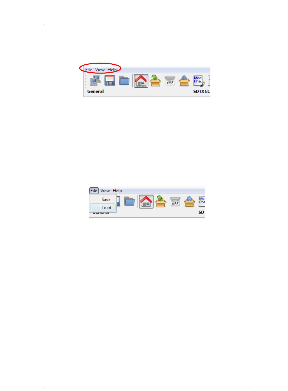
Screen Service SDT ARK 1 ECHO Operations
Jan, 2012 v 1.ATSC_FCC Page 3 - 92
3.11 System menu
Figure 24. Menu bar
The menu bar allows the access to three menus:
File: allows the enabling of load and save commands
View: allows to manage sections windows showing, java update time and
events alert massages
Help: informs about board name, GbE1 IP address, file system and operator
managing system characteristics.
3.11.1 File menu
Figure 25. File menu
The File menu allows the enabling of the following commands:
Save: allows device configuration saving creating a new *.sav file in the file system.
Load: allows last *.sav file loading from file system.

Screen Service SDT ARK 1 ECHO Operations
Jan, 2012 v 1.ATSC_FCC Page 3 - 93
3.11.2 View menu
Figure 26. View menu
The View menu allows the enabling of the following commands:
General: allows to access the general window.
Input: allows to access the input window.
Tuner: allows to access the Tuner window.
Output: allows to access the Output window.
Network: allows to access the Network window.
CAM: allows to access the PID manager window.
Input GPS: allows to access the Input GPS window.
Alarms: allows to access the Alarms window.
Events: allows to access the Events window.
Options: allows to access the Options sub-menu.
3.11.2.1 Option sub-menu
The Option sub-menu allows two controls type:
Time: Time Read Interval [s];
Alerts: the selection of events to display.
Click on the Save button to save Java options; a *.properties file will be created.
The device is not loaded with a factory default *.properties file, but it is created and then
stored in System File once the properties have been saved.
3.11.2.2 Time
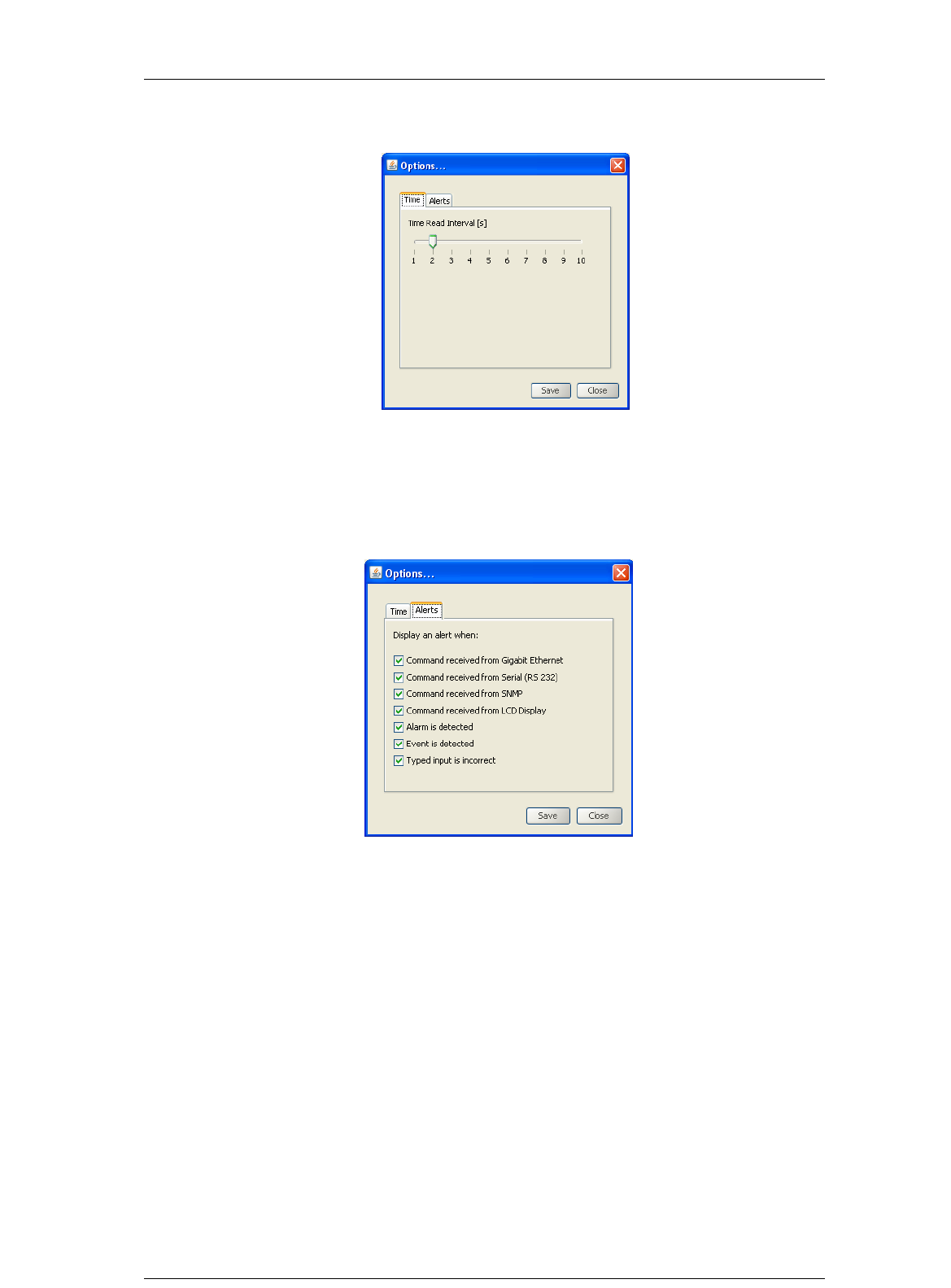
Screen Service SDT ARK 1 ECHO Operations
Jan, 2012 v 1.ATSC_FCC Page 3 - 94
Figure 27. Time window
This control allows changing the device-to-management PC java update time. The
default value is 2 seconds. Click on Close button quit this sub-window.
3.11.2.3 Alerts
Figure 28. Alerts window
The Alert sub-window allows selecting which types of events will be notified through an
Alert box.
Alert boxes appear on the right side of the monitor. The selection is performed among
the following types of event:
Commands (blue boxes):
o Gigabit Ethernet commands;
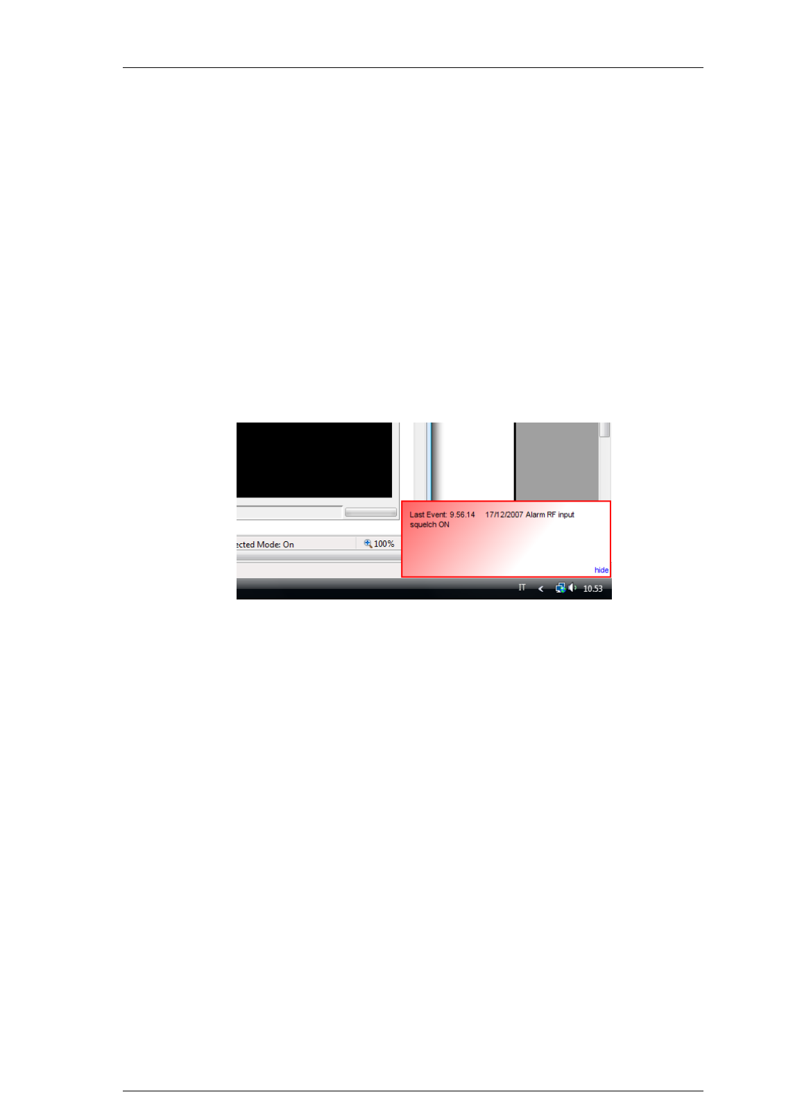
Screen Service SDT ARK 1 ECHO Operations
Jan, 2012 v 1.ATSC_FCC Page 3 - 95
o RS232 commands;
o SNMP commands;
o LCD Display commands.
Alarms (red boxes);
Events (green messages):
o Board events.
Typing error (yellow messages):
o Typed setting is incorrect.
Click on hide button to close these alert popup windows.
Figure 29. Alert message
Alert boxes can be disabled through the hide button located on the right side of the box.
The hide button, once clicked, disables all boxes belonging to the same class.
3.11.3 Help menu
Figure 30. Help menu
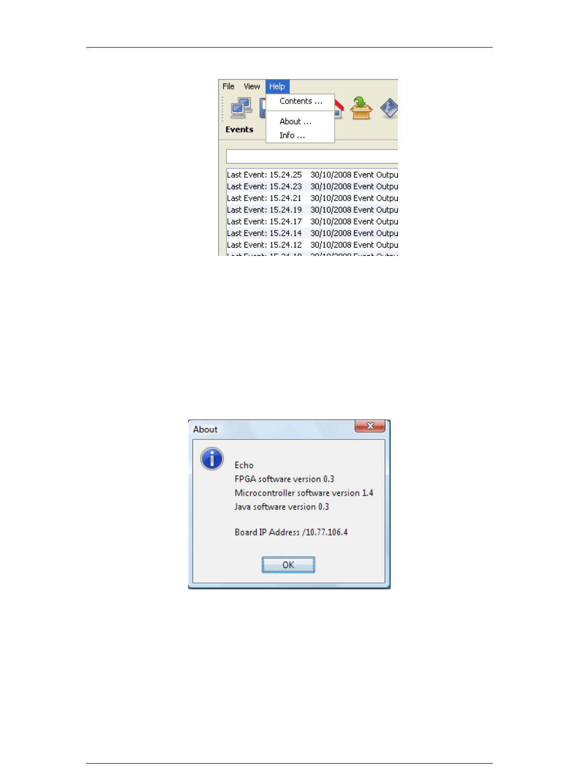
Screen Service SDT ARK 1 ECHO Operations
Jan, 2012 v 1.ATSC_FCC Page 3 - 96
The Help menu allows enabling the following controls type:
Contents: actually not implemented.
About: shows the board name and the GbE1 IP address. It also informs about
the board uC, fpga and java software versions.
Info: shows the board system files list and the operator managing system
characteristics.
3.11.3.1 About
Figure 31. About window
The “About” window shows the board name and the GbE1 IP address. It also informs
about the board uC, FPGA and Java software versions. Click on OK button to close
the window.
3.11.3.2 Info
Figure 32. Info window: file system content
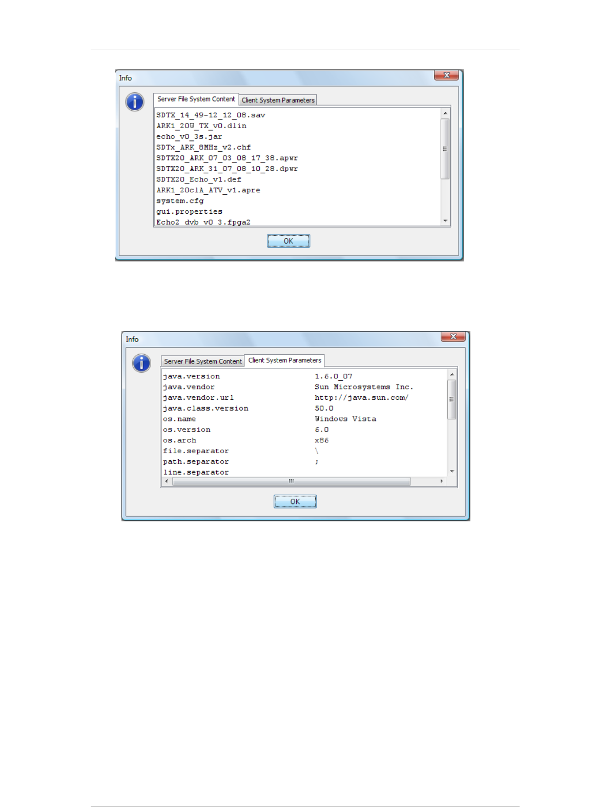
Screen Service SDT ARK 1 ECHO Operations
Jan, 2012 v 1.ATSC_FCC Page 3 - 97
The server file system content section of info window shows the entire board system
files list. Use scroll bars to view all the items.
Figure 33. Info window: client system parameters
The client system parameters section of info window shows the operator managing
system characteristics list. Use scroll bars to view all the items. Click on OK button to
close the window.
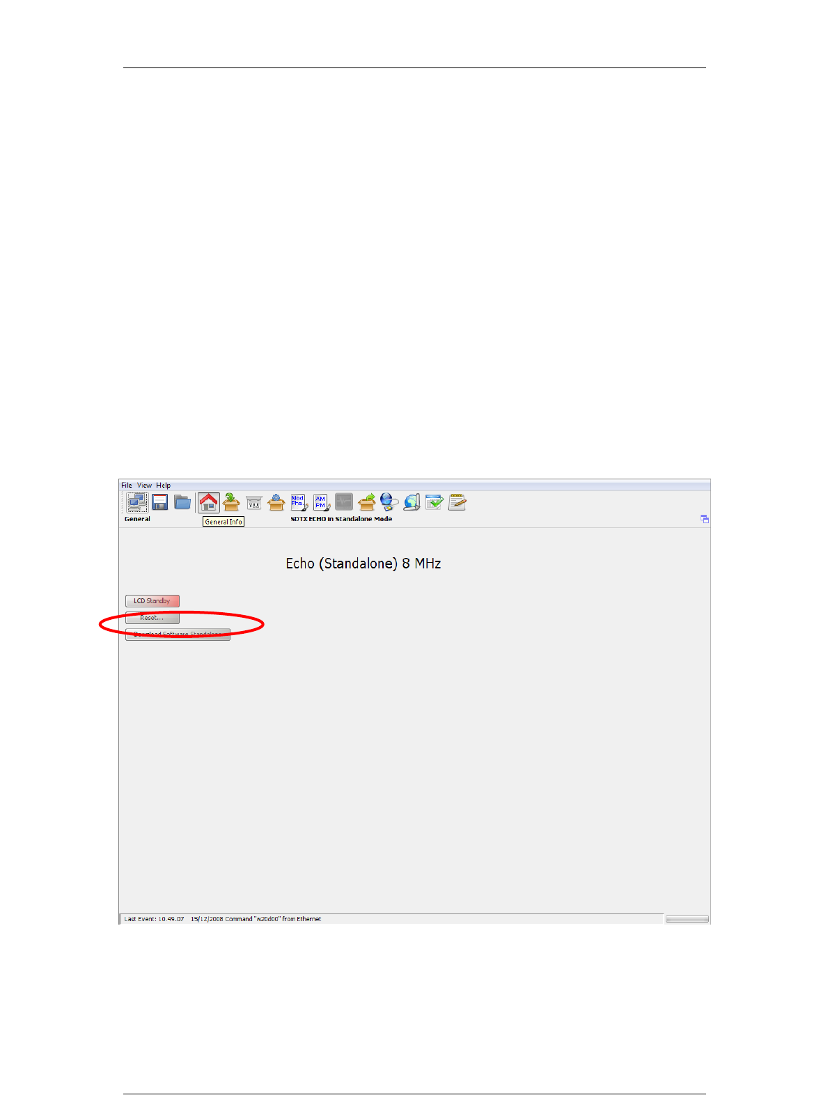
Screen Service SDT ARK 1 ECHO Operations
Jan, 2012 v 1.ATSC_FCC Page 3 - 98
3.12 Download Software Standalone
The Download Software Standalone button allows the downloading of standalone java
application (executable jar file) based on java applet.
If your browser is Internet Explorer, it may blocks the site from downloading files to your
computer. If you want to enable the file downloading, follow the instructions listed below:
Open Internet Explorer;
Click on the Tools button and then click on Internet Options;
Click on the Security tab and then click on Custom level button;
To turn off the Information bar for file downloads, scroll to the Downloads section
of the list, and then, under Automatic prompting for file downloads, click on
Enable;
Click on OK, click Yes in order to confirm that you want to make the change, and
then click OK again.
Figure 34. Download Software Standalone

Screen Service SDT ARK 1 ECHO Operations
Jan, 2012 v 1.ATSC_FCC Page 3 - 99
3.13 SNMP – Simple Network Management Protocol
The SNMP model assumes the existence of managers and agents. A manager is a
software module in a management system responsible for managing the device. An
agent is a software module in a managed device responsible for maintaining local
management information and delivering that information to a manager via SNMP. A
management information exchange can be initiated by the manager (via polling) or by
the agent (via trap).
Interaction between a user of board management and the board management software
takes place across a user interface. Such an interface is needed to provide users with a
monitoring and controlling tool in order to allow some parameters to be viewed or set
locally.
The operations that are supported in SNMP network management are the alteration and
inspection of variables. Specifically, three general-purpose operations may be performed
on scalar objects:
Get: a management station retrieves a scalar object value from a managed
station.
Set: a management station updates a scalar object value in a managed station.
Trap: a managed station sends an unsolicited scalar object value to a
management station.
Management information accessible via SNMP is maintained in a management
information base (MIB) at each manager and agent node.
On manager side, SDTX ECHO management system has been tested with MG-SOFT as
MIB Browser; besides compatibility with any other MIB browser is assured.
The following MIB libraries are required for the SNMP management of the equipment:
SCREENSERVICE-SCB-BROADCASTING-MIB.my;
echo_0_1.MY.
Compatibility tested and assured with SNMP version 1 and 2.
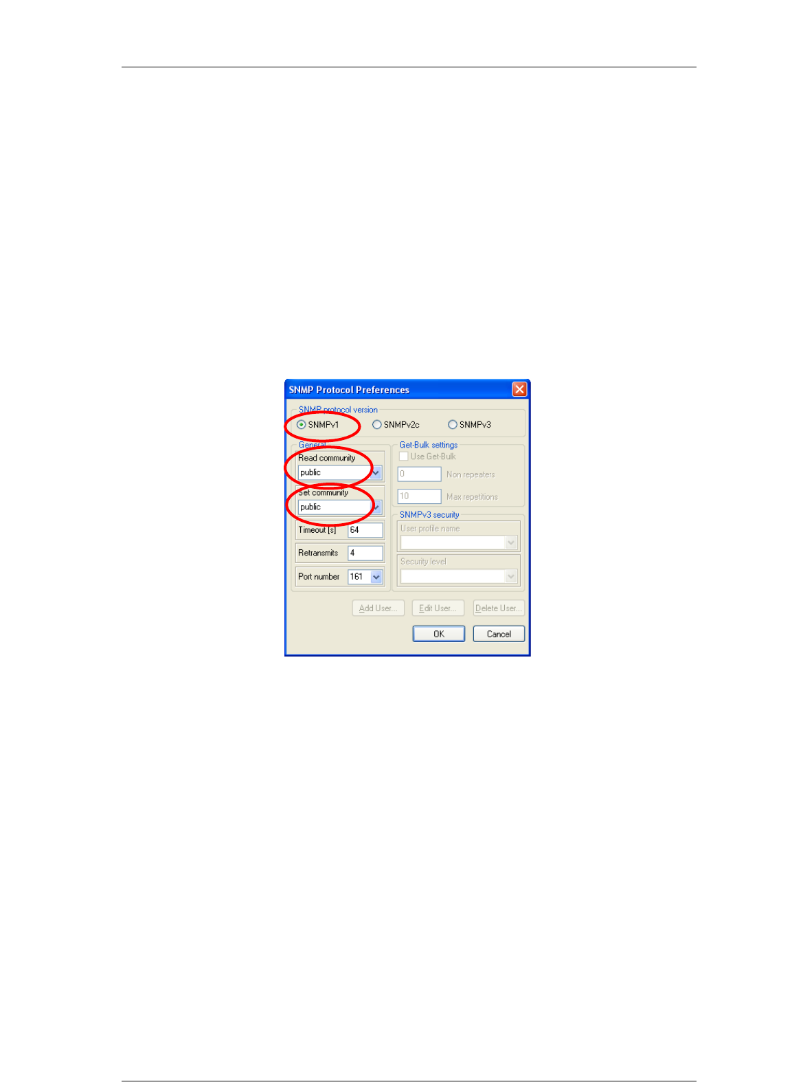
Screen Service SDT ARK 1 ECHO Operations
Jan, 2012 v 1.ATSC_FCC Page 3 - 100
3.14 SNMP Protocol Preferences
Go to SNMP Protocol Preferences. The following parameters should be set in order to
correctly configure the SNMP Manager:
SNMP protocol version: SNMPv1;
Read Community: the same of the one set in the Get field of Java interface,
community section;
Set Community: the same of the one set in the Set field of Java interface,
community section;
Timeout [s]: user defined;
Retransmits: user defined;
Port number: 161.
Next figure illustrates how to configure SNMP Protocol Preferences using MG_SOFT
MIB Browser as an example.
Figure 3.13-1: SNMP Protocol Preferences

Screen Service SDT ARK 1 ECHO Operations
Jan, 2012 v 1.ATSC_FCC Page 3 - 101
3.15 Communities
The following community strings are used by default.
Read Community: public.
Set Community: private.
Change in public the Set Community on the SNMP Protocol Preferences.
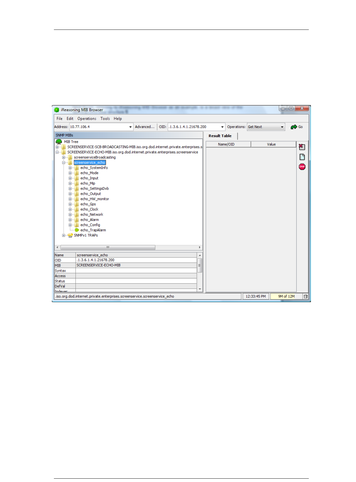
Screen Service SDT ARK 1 ECHO Operations
Jan, 2012 v 1.ATSC_FCC Page 3 - 102
3.16 Monitoring
All status and setup information can be queried via SNMP. To get the setup and status
information you need a management system (or a special MIB browser).
Next figure, referring to iReasoning MIB Browser as an example, is a broad view of the
SDTX ECHO tree structure.
Figure 35. SDTX ECHO MIB Browser

Screen Service SDT ARK 1 ECHO Operations
Jan, 2012 v 1.ATSC_FCC Page 3 - 103
3.17 OID
Any status and setup information has an OID (Object Identifier). The OID of the SDTX
ECHO system is:
screenservice_SDTx Echoc: 1.3.6.1.4.1.21678.200
iso(1).org(3).dod(6).internet(1).private(4).enterprises(1).screenservice(21678).sc
reenservice_echo(200)
3.17.1 SNMP tree structure
The SNMP tree structure is shown in the previous figure, after the node
screenserviceBroadcasting there is the node that specifies the device typology.
The screenservice_SDTx Echo tree has 12 nodes and 1 leave.
The nodes are:
echo_SystemInfo: global description of the system.
echo_Mode: shows and manages board modes.
echo_Input: shows and manages inputs.
Note: In Echo_STV0 and Echo_STV1 nodes are housed the statistics of the
digital RF signal. STV0 and STV1 are the two IF demodulators for the HP and
LP streams respectively.
echo_Mip: shows MIP modulation parameters.
echo_SettingsATSC: shows and sets local modulation parameters.
echo_Output: shows and manages the output.
echo_HW_monitor: shows the amplifier status.
echo_Gps: shows the collection of live data from GPS receiver.
echo_Clock: shows and sets 10MHz and 1PPS source.
echo_Network: shows and sets network parameters.
echo_Alarm: shows and manages system alarms.
echo_Config: allows the management of the machine configuration.
echo_TrapAlarm: is the OID used in the trap message.

Screen Service SDT ARK 1 ECHO Operations
Jan, 2012 v 1.ATSC_FCC Page 3 - 104
Table 19. SDTX ECHO SNMP Tree Structure
OID
Name
R\W
Description
1
iso
OBJ ID
1.3
org
OBJ ID
1.3.6
dod
OBJ ID
1.3.6.1
internet
OBJ ID
1.3.6.1.2
mgmt
OBJ ID
1.3.6.1.2.1
mib-2
OBJ ID
1.3.6.1.2.1.1
system
OBJ ID
1.3.6.1.2.1.1.1
sysDescr
R
1.3.6.1.2.1.1.2
sysObjectID
R
1.3.6.1.2.1.1.3
sysUpTimeInstance
R
1.3.6.1.2.1.1.4
sysContact
R
1.3.6.1.2.1.1.5
sysName
R
1.3.6.1.2.1.1.6
sysLocation
R
1.3.6.1.2.1.1.7
sysServices
R
1.3.6.1.4
private
OBJ ID
1.3.6.1.4.1
enterprise
OBJ ID
1.3.6.1.4.1.21678
screenservice
OBJ ID
1.3.6.1.4.1.21678.183
screenservice_echo
OBJ ID
1.3.6.1.4.1.21678.183.1
echo_SystemInfo
OBJ ID
1.3.6.1.4.1.21678.183.1.1
echo_SystemInfoIdentifier
R
Identification name of the equipment managed
1.3.6.1.4.1.21678.183.1.2
echo_SystemInfoName
R
Manufacturer name

Screen Service SDT ARK 1 ECHO Operations
Jan, 2012 v 1.ATSC_FCC Page 3 - 105
OID
Name
R\W
Description
1.3.6.1.4.1.21678.183.1.3
echo_SystemInfoDescription
R
Description of the equipment managed
1.3.6.1.4.1.21678.183.1.4
echo_SystemInfoLocation
R
Geographical implantation
1.3.6.1.4.1.21678.183.1.5
echo_SystemInfoContact
R
The person to contact in case of problems with the managed element
1.3.6.1.4.1.21678.183.1.6
echo_SystemInfoFamilyNumber
R
Device family number
1.3.6.1.4.1.21678.183.1.7
echo_SystemInfoId
R
System info ID
1.3.6.1.4.1.21678.183.1.8
echo_SystemInfoSerialNumber
R
Device serial number
1.3.6.1.4.1.21678.183.1.9
echo_SystemInfoVersion
OBJ ID
1.3.6.1.4.1.21678.183.1.9.1
echo_VersionUc
R
UC file version
1.3.6.1.4.1.21678.183.1.9.2
echo_VersionFpga
R
Fpga file version
1.3.6.1.4.1.21678.183.1.9.3
echo_VersionSnmp
R
Snmp file version
1.3.6.1.4.1.21678.183.1.9.4
echo_VersionPsu
OBJ ID
1.3.6.1.4.1.21678.183.1.9.4.1
echo_PsuFamily
R
PSU family number
1.3.6.1.4.1.21678.183.1.9.4.2
echo_PsuSerial
R
PSU serial number
1.3.6.1.4.1.21678.183.1.9.5
echo_VersionUpconverter
OBJ ID
1.3.6.1.4.1.21678.183.1.9.5.1
echo_UpconverterFamily
R
Upconverter family number
1.3.6.1.4.1.21678.183.1.9.5.2
echo_UpconverterSerial
R
Upconverter serial number
1.3.6.1.4.1.21678.183.1.9.5.3
echo_UpconverterLib
R
Upconverter software library number
1.3.6.1.4.1.21678.183.1.9.5.4
echo_UpconverterVer
R
Upconverter version
1.3.6.1.4.1.21678.183.2
echo_Mode
OBJ ID
1.3.6.1.4.1.21678.183.2.1
echo_ModeSwitch
RW
Switch mode selector 0:manual 1:auto 2:opto 3:time
1.3.6.1.4.1.21678.183.2.2
echo_ModeManualSelector
RW
Manual mode 0: modeA 1: modeB
1.3.6.1.4.1.21678.183.2.3
echo_ModeActual
R
Actual mode 0: modeA 1: modeB
1.3.6.1.4.1.21678.183.2.4
echo_ModeSelectorA
RW
Mode A selector 0: Rep Analog 1: Rep Digital 2: Tx ATSC

Screen Service SDT ARK 1 ECHO Operations
Jan, 2012 v 1.ATSC_FCC Page 3 - 106
OID
Name
R\W
Description
1.3.6.1.4.1.21678.183.2.5
echo_ModeSelectorB
RW
Mode B selector 0: Rep Analog 1: Rep Digital 2: Tx ATSC
1.3.6.1.4.1.21678.183.2.7
echo_ModeErrorFrequency
R
Frequency error correction expressed in Hz
1.3.6.1.4.1.21678.183.2.8
echo_ModeAFC_A
RW
Automatic Frequency Control mode A 0: disabled 1: enabled
1.3.6.1.4.1.21678.183.2.9
echo_ModeAFC_B
RW
Automatic Frequency Control mode B 0: disabled 1: enabled
1.3.6.1.4.1.21678.183.2.10
echo_ModeAFC_actual
R
Automatic Frequency Control status 0: disabled 1: enabled
1.3.6.1.4.1.21678.183.2.11
echo_ModeAutoSwitchTmo
RW
Auto-switch timeout (s)
1.3.6.1.4.1.21678.183.2.12
echo_ModeActualTmo
R
Actual auto-switch timeout (s)
1.3.6.1.4.1.21678.183.2.13
echo_ModeAutoSwitchRuleA
RW
Auto-switch rules mode A (bit to alarm association) bit 0: no RF input alarm
bit1: input squelch alarm bit2: no ts input alarm bit3: ber alarm bit4: S/N
alarm bit5: no MIP alarm
1.3.6.1.4.1.21678.183.2.14
echo_ModeAutoSwitchRuleB
RW
Auto-switch rules mode B (bit to alarm association) bit 0: no RF input alarm
bit1: input squelch alarm bit2: no ts input alarm bit3: ber alarm bit4: S/N
alarm bit5: no MIP alarm
1.3.6.1.4.1.21678.183.2.15
echo_ModeSwitchingTime
OBJ ID
1.3.6.1.4.1.21678.183.2.15.1
echo_SwitchingTimeYear
RW
Switching time: year setting (starting from 2000)
1.3.6.1.4.1.21678.183.2.15.2
echo_SwitchingTimeMonth
RW
Switching time: month setting
1.3.6.1.4.1.21678.183.2.15.3
echo_SwitchingTimeDay
RW
Switching time: day setting
1.3.6.1.4.1.21678.183.2.15.4
echo_SwitchingTimeHour
RW
Switching time: hour setting
1.3.6.1.4.1.21678.183.2.15.5
echo_SwitchingTimeMinutes
RW
Switching time: minutes setting
1.3.6.1.4.1.21678.183.2.15.6
echo_SwitchingTimeSeconds
RW
Switching time: seconds setting
1.3.6.1.4.1.21678.183.3
echo_Input
OBJ ID
1.3.6.1.4.1.21678.183.3.1
echo_InputSettings
OBJ ID
1.3.6.1.4.1.21678.183.3.1.1
echo_InputSettingsA
OBJ ID

Screen Service SDT ARK 1 ECHO Operations
Jan, 2012 v 1.ATSC_FCC Page 3 - 107
OID
Name
R\W
Description
1.3.6.1.4.1.21678.183.3.1.1.1
echo_InputSettingsA_Rf
OBJ ID
1.3.6.1.4.1.21678.183.3.1.1.1.1
echo_SettingsA_Rf_Channel
RW
Mode A: input channel
1.3.6.1.4.1.21678.183.3.1.1.1.2
echo_SettingsA_Rf_FrequencyOffset
RW
Mode A: input frequency offset expressed in Hz (from -4,000,000 up to
4,000,000)
1.3.6.1.4.1.21678.183.3.1.1.2
echo_InputSettingsA_Remod
OBJ ID
1.3.6.1.4.1.21678.183.3.1.1.2.1
echo_SettingsA_Remod_Hp
RW
Mode A: High Priority steam selector 0: asi 1 1: asi 2 2: asi 3 3: asi 4 4:
RX HP 5: RX LP 6: Gbe Port1 7: Gbe Port2
1.3.6.1.4.1.21678.183.3.1.1.2.2
echo_SettingsA_Remod_Lp
RW
Mode A: Low Priority steam selector 0: asi 1 1: asi 2 2: asi 3 3: asi 4 4:
RX HP 5: RX LP 6: Gbe Port1 7: Gbe Port2
1.3.6.1.4.1.21678.183.3.1.2
echo_InputSettingsB
OBJ ID
1.3.6.1.4.1.21678.183.3.1.2.1
echo_InputSettingsB_Rf
OBJ ID
1.3.6.1.4.1.21678.183.3.1.2.1.1
echo_SettingsB_Rf_Channel
RW
Mode B: input channel
1.3.6.1.4.1.21678.183.3.1.2.1.2
echo_SettingsB_Rf_FrequencyOffset
RW
Mode B: input frequency offset expressed in Hz (from -4,000,000 up to
4,000,000)
1.3.6.1.4.1.21678.183.3.1.2.2
echo_InputSettingsB_Remod
OBJ ID
1.3.6.1.4.1.21678.183.3.1.2.2.1
echo_SettingsB_Remod_Hp
RW
Mode B: High Priority steam selector 0: asi 1 1: asi 2 2: asi 3 3: asi 4 4:
RX HP 5: RX LP 6: Gbe Port1 7: Gbe Port2
1.3.6.1.4.1.21678.183.3.1.2.2.2
echo_SettingsB_Remod_Lp
RW
Mode B: Low Priority steam selector 0: asi 1 1: asi 2 2: asi 3 3: asi 4 4:
RX HP 5: RX LP 6: Gbe Port1 7: Gbe Port2
1.3.6.1.4.1.21678.183.3.2
echo_InputStatistics
OBJ ID
1.3.6.1.4.1.21678.183.3.2.1
echo_StatisticsRf
OBJ ID
1.3.6.1.4.1.21678.183.3.2.1.1
echo_RfRxLevel
R
Input RX level 0: over input 255: low power 1...254: power (absolute value
expressed in dBm)

Screen Service SDT ARK 1 ECHO Operations
Jan, 2012 v 1.ATSC_FCC Page 3 - 108
OID
Name
R\W
Description
1.3.6.1.4.1.21678.183.3.2.1.2
echo_RfAnalog
OBJ ID
1.3.6.1.4.1.21678.183.3.2.1.2.1
echo_VSync
R
PAL detector 0: No 1: Yes
1.3.6.1.4.1.21678.183.3.2.1.3
echo_RfDigital
OBJ ID
1.3.6.1.4.1.21678.183.3.2.1.3.1
echo_RxATSCLp
OBJ ID
1.3.6.1.4.1.21678.183.3.2.1.3.1.1
echo_RxATSCLp_PckRate
R
Input Rx HP: packet rate
1.3.6.1.4.1.21678.183.3.2.1.3.1.2
echo_RxATSCLp_UsedPckrate
R
Input Rx HP: filtered packet rate
1.3.6.1.4.1.21678.183.3.2.1.3.1.3
echo_RxATSCLp_Lock
R
Input Rx HP: lock alarm 0: unlock 1: lock
1.3.6.1.4.1.21678.183.3.2.1.3.1.4
echo_RxATSCLp_OverFlowAlarm
R
Input Rx HP: overflow alarm 0: off 1: on
1.3.6.1.4.1.21678.183.3.2.1.3.2
echo_RxATSCLp
OBJ ID
1.3.6.1.4.1.21678.183.3.2.1.3.2.1
echo_RxATSCLp_Pckrate
R
Input Rx LP: packet rate
1.3.6.1.4.1.21678.183.3.2.1.3.2.2
echo_RxATSCLp_UsedPckrate
R
Input Rx LP: filtered packet rate
1.3.6.1.4.1.21678.183.3.2.1.3.2.3
echo_RxATSCLp_Lock
R
Input Rx LP: lock alarm 0: unlock 1: lock
1.3.6.1.4.1.21678.183.3.2.1.3.2.4
echo_RxATSCLp_OverFlowAlarm
R
Input Rx LP: overflow alarm 0: off 1: on
1.3.6.1.4.1.21678.183.3.2.1.3.3
echo_STV0
OBJ ID
1.3.6.1.4.1.21678.183.3.2.1.3.3.1
echo_STV0LockTps
R
STV 0: TPS lock status 0: unlock 1: lock
1.3.6.1.4.1.21678.183.3.2.1.3.3.2
echo_STV0LockSyr
R
STV 0: symbol recovery loop lock status 0: unlock 1: lock
1.3.6.1.4.1.21678.183.3.2.1.3.3.3
echo_STV0LockPunctureRate
R
STV 0: puncture rate found 0: not found 1: found
1.3.6.1.4.1.21678.183.3.2.1.3.3.4
echo_STV0LockDeinterleaver
R
STV 0: de-interleaver lock status 0: unlock 1: lock
1.3.6.1.4.1.21678.183.3.2.1.3.3.5
echo_STV0DemodBerRate
R
STV 0: demudulator Bit Error Rate
1.3.6.1.4.1.21678.183.3.2.1.3.3.6
echo_STV0ViterbiBerRate
R
STV 0: Viterbi Bit Error Rate
1.3.6.1.4.1.21678.183.3.2.1.3.3.7
echo_STV0PckErr
R
STV 0: packet error count
1.3.6.1.4.1.21678.183.3.2.1.3.3.8
echo_STV0Snr
R
STV 0: estimated Signal-to-Noise Ratio expressed in dB
1.3.6.1.4.1.21678.183.3.2.1.3.3.9
echo_STV0Constallation
R
STV 0: constellation for current modulation scheme 0: QPSK 1: 16-QAM 2:

Screen Service SDT ARK 1 ECHO Operations
Jan, 2012 v 1.ATSC_FCC Page 3 - 109
OID
Name
R\W
Description
64-QAM
1.3.6.1.4.1.21678.183.3.2.1.3.3.10
echo_STV0HierMode
R
STV 0: hierarchy information for current scheme 0: non hierarchical 1:
alpha=1 2: alpha=2 3: alpha=4
1.3.6.1.4.1.21678.183.3.2.1.3.3.11
echo_STV0Interleaver
R
STV 0: native/in-depth symbol interleaver for current scheme 0: native 1: in-
depth
1.3.6.1.4.1.21678.183.3.2.1.3.3.12
echo_STV0Fec
R
STV 0: High Priority FEC 0: 1/2 1: 2/3 2: 3/4 3: 5/6 4: 7/8
1.3.6.1.4.1.21678.183.3.2.1.3.3.13
echo_STV0Fft
R
STV 0: transmission mode information 0: 2K 1: 8K 2: 4K
1.3.6.1.4.1.21678.183.3.2.1.3.3.14
echo_STV0GuardTime
R
STV 0: guard interval 0: 1/32 1: 1/16 2: 1/8 3: 1/4
1.3.6.1.4.1.21678.183.3.2.1.3.3.15
echo_STV0CelllId
R
STV 0: cell identifier
1.3.6.1.4.1.21678.183.3.2.1.3.4
echo_STV1
OBJ ID
1.3.6.1.4.1.21678.183.3.2.1.3.4.1
echo_STV1LockTps
R
STV 1: TPS lock status 0: unlock 1: lock
1.3.6.1.4.1.21678.183.3.2.1.3.4.2
echo_STV1LockSyr
R
STV 1: symbol recovery loop lock status 0: unlock 1: lock
1.3.6.1.4.1.21678.183.3.2.1.3.4.3
echo_STV1LockPunctureRate
R
STV 1: puncture rate found 0: not found 1: found
1.3.6.1.4.1.21678.183.3.2.1.3.4.4
echo_STV1LockDeinterleaver
R
STV 1: de-interleaver lock status 0: unlock 1: lock
1.3.6.1.4.1.21678.183.3.2.1.3.4.5
echo_STV1DemodBerRate
R
STV 1: demudulator Bit Error Rate
1.3.6.1.4.1.21678.183.3.2.1.3.4.6
echo_STV1ViterbiBer
R
STV 1: Viterbi Bit Error Rate
1.3.6.1.4.1.21678.183.3.2.1.3.4.7
echo_STV1PckErr
R
STV 1: packet error count
1.3.6.1.4.1.21678.183.3.2.1.3.4.8
echo_STV1Snr
R
STV 1: estimated Signal-to-Noise Ratio expressed in dB
1.3.6.1.4.1.21678.183.3.2.1.3.4.9
echo_STV1Constallation
R
STV 1: constellation for current modulation scheme 0: QPSK 1: 16-QAM 2:
64-QAM
1.3.6.1.4.1.21678.183.3.2.1.3.4.10
echo_STV1HierMode
R
STV1: hierarchy information for current scheme 0: non hierarchical 1:
alpha=1 2: alpha=2 3: alpha=4
1.3.6.1.4.1.21678.183.3.2.1.3.4.11
echo_STV1Interleaver
R
STV 1: native/in-depth symbol interleaver for current scheme 0: native 1: in-

Screen Service SDT ARK 1 ECHO Operations
Jan, 2012 v 1.ATSC_FCC Page 3 - 110
OID
Name
R\W
Description
depth
1.3.6.1.4.1.21678.183.3.2.1.3.4.12
echo_STV1Fec
R
STV1: Low Priority FEC 0: 1/2 1: 2/3 2: 3/4 3: 5/6 4: 7/8
1.3.6.1.4.1.21678.183.3.2.1.3.4.13
echo_STV1Fft
R
STV 1: transmission mode information 0: 2K 1: 8K 2: 4K
1.3.6.1.4.1.21678.183.3.2.1.3.4.14
echo_STV1GuardTime
R
STV 1: guard interval 0: 1/32 1: 1/16 2: 1/8 3: 1/4
1.3.6.1.4.1.21678.183.3.2.1.3.4.15
echo_STV1CelllId
STV 1: cell identifier
1.3.6.1.4.1.21678.183.3.2.2
echo_StatisticsRemod
OBJ ID
1.3.6.1.4.1.21678.183.3.2.2.1
echo_RemodAsi
OBJ ID
1.3.6.1.4.1.21678.183.3.2.2.1.1
echo_Asi1
OBJ ID
1.3.6.1.4.1.21678.183.3.2.2.1.1.1
echo_Asi1WordRate
R
Asi 1 input word rate
1.3.6.1.4.1.21678.183.3.2.2.1.1.2
echo_Asi1ByteRate
R
Asi 1 input byte rate
1.3.6.1.4.1.21678.183.3.2.2.1.1.3
echo_Asi1Filtered
R
Asi 1 filtered byte rate
1.3.6.1.4.1.21678.183.3.2.2.1.1.4
echo_Asi1OverFlowAlarm
R
Asi 1 overflow alarm 0: off 1: on
1.3.6.1.4.1.21678.183.3.2.2.1.1.5
echo_Asi1Lock
R
Asi 1 lock status 0: unlock 1: lock
1.3.6.1.4.1.21678.183.3.2.2.1.1.6
echo_Asi1PacketFormat
R
Asi 1 packet format 0: 204 1: 188
1.3.6.1.4.1.21678.183.3.2.2.1.1.7
echo_Asi1Cd
R
Asi 1 carrier detect alarm 0: unlock 1: lock
1.3.6.1.4.1.21678.183.3.2.2.1.1.8
echo_Asi1Errors
R
Asi 1 wrong bytes received (pay attention: when the input is not connected it is
different from zero)
1.3.6.1.4.1.21678.183.3.2.2.1.2
echo_Asi2
OBJ ID
1.3.6.1.4.1.21678.183.3.2.2.1.2.1
echo_Asi2WordRate
R
Asi 2 input word rate
1.3.6.1.4.1.21678.183.3.2.2.1.2.2
echo_Asi2ByteRate
R
Asi 2 input byte rate
1.3.6.1.4.1.21678.183.3.2.2.1.2.3
echo_Asi2Filtered
R
Asi 2 filtered byte rate
1.3.6.1.4.1.21678.183.3.2.2.1.2.4
echo_Asi2OverFlowAlarm
R
Asi 2 overflow alarm 0: off 1: on
1.3.6.1.4.1.21678.183.3.2.2.1.2.5
echo_Asi2Lock
R
Asi 2 lock status 0: unlock 1: lock

Screen Service SDT ARK 1 ECHO Operations
Jan, 2012 v 1.ATSC_FCC Page 3 - 111
OID
Name
R\W
Description
1.3.6.1.4.1.21678.183.3.2.2.1.2.6
echo_Asi2PacketFormat
R
Asi 2 packet format 0: 204 1: 188
1.3.6.1.4.1.21678.183.3.2.2.1.2.7
echo_Asi2Cd
R
Asi 2 carrier detect alarm 0: unlock 1: lock
1.3.6.1.4.1.21678.183.3.2.2.1.2.8
echo_Asi2Errors
R
Asi 2 wrong bytes received (pay attention: when the input is not connected it is
different from zero)
1.3.6.1.4.1.21678.183.3.2.2.1.3
echo_Asi3
OBJ ID
1.3.6.1.4.1.21678.183.3.2.2.1.3.1
echo_Asi3WordRate
R
Asi 3 input word rate
1.3.6.1.4.1.21678.183.3.2.2.1.3.2
echo_Asi3ByteRate
R
Asi 3 input byte rate
1.3.6.1.4.1.21678.183.3.2.2.1.3.3
echo_Asi3Filtered
R
Asi 3 filtered byte rate
1.3.6.1.4.1.21678.183.3.2.2.1.3.4
echo_Asi3OverFlowAlarm
R
Asi 3 overflow alarm 0: off 1: on
1.3.6.1.4.1.21678.183.3.2.2.1.3.5
echo_Asi3Lock
R
Asi 3 lock status 0: unlock 1: lock
1.3.6.1.4.1.21678.183.3.2.2.1.3.6
echo_Asi3PacketFormat
R
Asi 3 packet format 0: 204 1: 188
1.3.6.1.4.1.21678.183.3.2.2.1.3.7
echo_Asi3Cd
R
Asi 3 carrier detect alarm 0: unlock 1: lock
1.3.6.1.4.1.21678.183.3.2.2.1.3.8
echo_Asi3Errors
R
Asi 3 wrong bytes received (pay attention: when the input is not connected it is
different from zero)
1.3.6.1.4.1.21678.183.3.2.2.1.4
echo_Asi4
OBJ ID
1.3.6.1.4.1.21678.183.3.2.2.1.4.1
echo_Asi4WordRate
R
Asi 4 input word rate
1.3.6.1.4.1.21678.183.3.2.2.1.4.2
echo_Asi4ByteRate
R
Asi 4 input byte rate
1.3.6.1.4.1.21678.183.3.2.2.1.4.3
echo_Asi4Filtered
R
Asi 4 filtered byte rate
1.3.6.1.4.1.21678.183.3.2.2.1.4.4
echo_Asi4OverFlowAlarm
R
Asi 4 overflow alarm 0: off 1: on
1.3.6.1.4.1.21678.183.3.2.2.1.4.5
echo_Asi4Lock
R
Asi 4 lock status 0: unlock 1: lock
1.3.6.1.4.1.21678.183.3.2.2.1.4.6
echo_Asi4PacketFormat
R
Asi 4 packet format 0: 204 1: 188
1.3.6.1.4.1.21678.183.3.2.2.1.4.7
echo_Asi4Cd
R
Asi 4 carrier detect alarm 0: unlock 1: lock
1.3.6.1.4.1.21678.183.3.2.2.1.4.8
echo_Asi4Errors
R
Asi 4 wrong bytes received (pay attention: when the input is not connected it is

Screen Service SDT ARK 1 ECHO Operations
Jan, 2012 v 1.ATSC_FCC Page 3 - 112
OID
Name
R\W
Description
different from zero)
1.3.6.1.4.1.21678.183.3.2.2.2
echo_RemodGbe
OBJ ID
1.3.6.1.4.1.21678.183.3.2.2.2.1
echo_GbePckCounter
R
Good frame count
1.3.6.1.4.1.21678.183.3.2.2.2.2
echo_GbeErrors
R
Bad frame count
1.3.6.1.4.1.21678.183.3.2.2.2.3
echo_GbePort1
OBJ ID
1.3.6.1.4.1.21678.183.3.2.2.2.3.1
echo_GbePort1PckRate
R
Gigabit Ethernet 1 input packet rate
1.3.6.1.4.1.21678.183.3.2.2.2.3.2
echo_GbePort1Filtered
R
Gigabit Ethernet 1 filtered packet rate
1.3.6.1.4.1.21678.183.3.2.2.2.3.3
echo_GbePort1PacketFormat
R
Gigabit Ethernet 1 packet format 0: 204 01: 188 3: not valid
1.3.6.1.4.1.21678.183.3.2.2.2.3.4
echo_GbePort1Lock
R
Gigabit Ethernet 1 lock lock status 0: unlock 1: lock
1.3.6.1.4.1.21678.183.3.2.2.2.3.5
echo_GbePort1OverFlowAlarm
R
Gigabit Ethernet 1 overflow alarm 0: off 1: on
1.3.6.1.4.1.21678.183.3.2.2.2.3.6
echo_GbePort1SequenceError
R
NOT IMPLEMENTED (Gigabit Ethernet 1 sequence error 0: off 1: on)
1.3.6.1.4.1.21678.183.3.2.2.2.3.7
echo_GbePort1Protocol
R
Gigabit Ethernet 1 transmission protocol 0: udp 1: rtp
1.3.6.1.4.1.21678.183.3.2.2.2.4
echo_GbePort2
OBJ ID
1.3.6.1.4.1.21678.183.3.2.2.2.4.1
echo_GbePort2PcktRate
R
Gigabit Ethernet 2 input packet rate
1.3.6.1.4.1.21678.183.3.2.2.2.4.2
echo_GbePort2Filtered
R
Gigabit Ethernet 2 filtered packet rate
1.3.6.1.4.1.21678.183.3.2.2.2.4.3
echo_GbePort2PacketFormat
R
Gigabit Ethernet 2 packet format 0: 204 01: 188 3: not valid
1.3.6.1.4.1.21678.183.3.2.2.2.4.4
echo_GbePort2Lock
R
Gigabit Ethernet 2 lock lock status 0: unlock 1: lock
1.3.6.1.4.1.21678.183.3.2.2.2.4.5
echo_GbePort2OverFlowAlarm
R
Gigabit Ethernet 2 overflow alarm 0: off 1: on
1.3.6.1.4.1.21678.183.3.2.2.2.4.6
echo_GbePort2SequenceError
R
NOT IMPLEMENTED (Gigabit Ethernet 2 sequence error 0: off 1: on)
1.3.6.1.4.1.21678.183.3.2.2.2.4.7
echo_GbePort2Protocol
R
Gigabit Ethernet 2 transmission protocol 0: udp 1: rtp
1.3.6.1.4.1.21678.183.4
echo_Mip
OBJ ID
1.3.6.1.4.1.21678.183.4.1
echo_MipDetect
OBJ ID
1.3.6.1.4.1.21678.183.4.1.1
echo_DetectHp
R
High priority MIP detect 0: not detected 1: detected

Screen Service SDT ARK 1 ECHO Operations
Jan, 2012 v 1.ATSC_FCC Page 3 - 113
OID
Name
R\W
Description
1.3.6.1.4.1.21678.183.4.1.2
echo_DetectLp
R
Low priority MIP detect 0: not detected 1: detected
1.3.6.1.4.1.21678.183.4.2
echo_MipTxId
OBJ ID
1.3.6.1.4.1.21678.183.4.2.1
echo_TxId
RW
Transmitter identifier
1.3.6.1.4.1.21678.183.4.2.2
echo_TxId0Enable
RW
TX ID 0 enable 0: disabled 1: enabled
1.3.6.1.4.1.21678.183.4.3
echo_MipConstallation
R
MIP Constellation 0: QPSK 1: 16-QAM 2: 64-QAM
1.3.6.1.4.1.21678.183.4.4
echo_MipInterleaver
R
MIP native/in-depth symbol interleaver selector 0: native 1: in-depth
1.3.6.1.4.1.21678.183.4.5
echo_MipAlpha
R
MIP alpha 0: not hierarchical 1: alpha=1 2: alpha=2 3: alpha=4
1.3.6.1.4.1.21678.183.4.6
echo_MipGuardTime
R
MIP guard interval 0:1/32 1:1/16 2:1/8 3:1/4
1.3.6.1.4.1.21678.183.4.7
echo_MipFft
R
MIP transmission mode 0:2K 1:8K 2:4K
1.3.6.1.4.1.21678.183.4.8
echo_MipBandwidth
R
MIP bandwidth 0: 7MHz 1: 8MHz 2: 6MHz 3: 5MHz
1.3.6.1.4.1.21678.183.4.9
echo_MipFec
OBJ ID
1.3.6.1.4.1.21678.183.4.9.1
echo_MipFecHp
R
MIP High priority FEC 0: 1/2 1: 2/3 2: 3/4 3: 5/6 4: 7/8
1.3.6.1.4.1.21678.183.4.9.2
echo_MipFecLp
R
MIP Low priority FEC 0: 1/2 1: 2/3 2: 3/4 3: 5/6 4: 7/8
1.3.6.1.4.1.21678.183.4.10
echo_MipTimeSlicing
OBJ ID
1.3.6.1.4.1.21678.183.4.10.1
echo_MipTimeSlicingHp
R
MIP High priority time slicing 0: not used 1: used
1.3.6.1.4.1.21678.183.4.10.2
echo_MipTimeSlicingLp
R
MIP Low priority time slicing 0: not used 1: used
1.3.6.1.4.1.21678.183.4.11
echo_MipMpeFec
OBJ ID
1.3.6.1.4.1.21678.183.4.11.1
echo_MipMpeFecHp
R
High priority MPE-FEC 0: not used 1: used
1.3.6.1.4.1.21678.183.4.11.2
echo_MipMpeFecLp
R
Low priority MPE-FEC 0: not used 1: used
1.3.6.1.4.1.21678.183.4.12
echo_MipDelayTx
R
MIP transmission delay
1.3.6.1.4.1.21678.183.4.13
echo_MipMaxDelay
R
MIP maximum delay [100ns]
1.3.6.1.4.1.21678.183.4.14
echo_MipTimeOffset
OBJ ID
1.3.6.1.4.1.21678.183.4.14.1
echo_TimeOffsetEnable
RW
MIP time offset enable

Screen Service SDT ARK 1 ECHO Operations
Jan, 2012 v 1.ATSC_FCC Page 3 - 114
OID
Name
R\W
Description
1.3.6.1.4.1.21678.183.4.14.2
echo_TimeOffsetStatus
R
MIP time offset [100ns]
1.3.6.1.4.1.21678.183.4.15
echo_MipFrequencyOffset
OBJ ID
1.3.6.1.4.1.21678.183.4.15.1
echo_FrequencyOffsetEnable
RW
MIP frequency offset enable 0: disabled 1: enabled
1.3.6.1.4.1.21678.183.4.15.2
echo_FrequencyOffsetStatus
R
MIP frequency offset [Hz]
1.3.6.1.4.1.21678.183.4.16
echo_MipTxPower
OBJ ID
1.3.6.1.4.1.21678.183.4.16.1
echo_TxPoweEnable
R
NOT IMPLEMENTED (MIP transmission power enable 0: disabled 1:
enabled)
1.3.6.1.4.1.21678.183.4.16.2
echo_TxPowerStatus
R
MIP transmission power [0.1 dB]
1.3.6.1.4.1.21678.183.4.17
echo_MipCellId
OBJ ID
1.3.6.1.4.1.21678.183.4.17.1
echo_CellIdEnable
RW
Cell id function enable 0: disabled 1: enabled
1.3.6.1.4.1.21678.183.4.17.2
echo_CellIdFunctionEnable
R
Enable function status 0: not received 1: received
1.3.6.1.4.1.21678.183.4.17.3
echo_CellIdFunctionTag
R
Cell id function tag 0: not detected 1: detected
1.3.6.1.4.1.21678.183.4.17.4
echo_CellIdStatus
R
Cell id function
1.3.6.1.4.1.21678.183.4.17.5
echo_CellIdWaitForEnable
R
Cell id function wait for enable 0: disabled 1: enabled
1.3.6.1.4.1.21678.183.4.18
echo_MipFunctionBw
OBJ ID
1.3.6.1.4.1.21678.183.4.18.1
echo_FunctionBwEnable
R
NOT IMPLEMENTED (Bandwidth function enable 0: disabled 1: enabled)
1.3.6.1.4.1.21678.183.4.18.2
echo_FunctionBwStatus
R
Bandwidth function 0: 5MHz 1: reserved for future use
1.3.6.1.4.1.21678.183.4.18.3
echo_FunctionBwEnableRx
R
Enable function status 0: not received 1: received
1.3.6.1.4.1.21678.183.4.18.4
echo_FunctionChBwTag
R
Bandwidth function tag 0: not detected 1: detected
1.3.6.1.4.1.21678.183.4.18.5
echo_FunctionChBwWaitForEnable
R
Channel bandwith function wait for enabled 0: disabled 1: enabled
1.3.6.1.4.1.21678.183.5
echo_SettingsATSC
OBJ ID
1.3.6.1.4.1.21678.183.5.1
echo_SettingsCellIdEnable
RW
Cell Id enable 0: disabled 1: enabled
1.3.6.1.4.1.21678.183.5.3
echo_SettingsTxModeSel
OBJ ID

Screen Service SDT ARK 1 ECHO Operations
Jan, 2012 v 1.ATSC_FCC Page 3 - 115
OID
Name
R\W
Description
1.3.6.1.4.1.21678.183.5.3.1
echo_TxModeSelATSC_T_H
RW
Transmitter mode selection 0 : ATSC 1: ATSC
1.3.6.1.4.1.21678.183.5.3.2
echo_TxModeSel_Mfn_Sfn
RW
Transmitter mode selection 0 : MFN 1: SFN
1.3.6.1.4.1.21678.183.5.3.3
echo_TxModeSel_Mip
RW
Transmitter mode selection 0 : Local 1: MIP
1.3.6.1.4.1.21678.183.5.4
echo_SettingsLocal
OBJ ID
1.3.6.1.4.1.21678.183.5.4.2
echo_LocalFft
RW
Transmission mode selector 0: 2K 1: 8K 2: 4K
1.3.6.1.4.1.21678.183.5.4.3
echo_LocalGuardTime
RW
Guard time selector 0: 1/32 1: 1/16 2: 1/8 3: 1/4
1.3.6.1.4.1.21678.183.5.4.4
echo_LocalAlpha
RW
Alpha selector 0: NH 1: alpha=1 2: alpha=2 3: alpha=4
1.3.6.1.4.1.21678.183.5.4.5
echo_LocalConstellation
RW
Constellation selector 0: QPSK 1: 16-QAM 2: 64-QAM
1.3.6.1.4.1.21678.183.5.4.6
echo_LocalSettingsFec
OBJ ID
1.3.6.1.4.1.21678.183.5.4.6.1
echo_SettingsFecHp
RW
High priority FEC 0: 1/2 1: 2/3 2: 3/4 3: 5/6 4: 7/8
1.3.6.1.4.1.21678.183.5.4.6.2
echo_SettingsFecLP
RW
Low priority FEC 0: 1/2 1: 2/3 2: 3/4 3: 5/6 4: 7/8
1.3.6.1.4.1.21678.183.5.4.7
echo_LocalCellId
RW
Local cell id setting
1.3.6.1.4.1.21678.183.5.4.8
echo_LocalInterleaver
RW
Symbol interleaver selector 0: native 1: in-depth
1.3.6.1.4.1.21678.183.5.4.9
echo_LocalTimeSlicing
OBJ ID
1.3.6.1.4.1.21678.183.5.4.9.1
echo_TimeSlicingHp
RW
High priority time slicing 0: not used 1: used
1.3.6.1.4.1.21678.183.5.4.9.2
echo_TimeSlicingLp
RW
Low priority time slicing 0: not used 1: used
1.3.6.1.4.1.21678.183.5.4.10
echo_LocalMpeFecUsed
OBJ ID
1.3.6.1.4.1.21678.183.5.4.10.1
echo_MpeFecHp
RW
High priority MPE-FEC 0: not used 1: used
1.3.6.1.4.1.21678.183.5.4.10.2
echo_MpeFecLp
RW
Low priority MPE-FEC 0: not used 1: used
1.3.6.1.4.1.21678.183.5.4.11
echo_LocalTimeOffset
RW
Time offset setting (-32768..32767)
1.3.6.1.4.1.21678.183.5.4.12
echo_LocalFrequencyOffset
RW
Frequency offset setting (from -8388608 up to 8388607)
1.3.6.1.4.1.21678.183.5.4.13
echo_LocalDelay
RW
User delay setting (-8388608..8388607)
1.3.6.1.4.1.21678.183.6
echo_Output
OBJ ID

Screen Service SDT ARK 1 ECHO Operations
Jan, 2012 v 1.ATSC_FCC Page 3 - 116
OID
Name
R\W
Description
1.3.6.1.4.1.21678.183.6.1
echo_OutputSettings
OBJ ID
1.3.6.1.4.1.21678.183.6.1.1
echo_OutputSettingsA
OBJ ID
1.3.6.1.4.1.21678.183.6.1.1.1
echo_SettingsAChannel
RW
Mode A: output channel
1.3.6.1.4.1.21678.183.6.1.1.2
echo_SettingsAFrequencyOffset
RW
Mode A: output frequency offset expressed in Hz (from -4,000,000 up to
4,000,000)
1.3.6.1.4.1.21678.183.6.1.1.3
echo_SettingsAPower
RW
Mode A: output power
1.3.6.1.4.1.21678.183.6.1.2
echo_OutputSettingsB
OBJ ID
1.3.6.1.4.1.21678.183.6.1.2.1
echo_SettingsBChannel
RW
Mode B: output channel
1.3.6.1.4.1.21678.183.6.1.2.2
echo_SettingsBFrequencyOffset
RW
Mode B: output frequency offset expressed in Hz (from -4,000,000 up to
4,000,000)
1.3.6.1.4.1.21678.183.6.1.2.3
echo_SettingsBPower
RW
Mode B: output power
1.3.6.1.4.1.21678.183.6.1.3
echo_OutputSettingsGbe
OBJ ID
1.3.6.1.4.1.21678.183.6.1.3.1
echo_SettingsGbe0
OBJ ID
1.3.6.1.4.1.21678.183.6.1.3.1.1
echo_Gbe0Selector
RW
Input to Gigabit Ethernet 0 selector 0: asi 1 1: asi 2 2: asi 3 3: asi 4 4:
RX HP 5: RX LP 6: Gbe Port1 7: Gbe Port2
1.3.6.1.4.1.21678.183.6.1.3.1.2
echo_Gbe0Status
R
Tx channel 1: transmission status 0: off 1: Resolving IP 2: No entry error
3: TX data 4: IP address not found 5: TX multicast data
1.3.6.1.4.1.21678.183.6.1.3.1.3
echo_Gbe0Enable
RW
Tx channel 1: transmission enable 0: disabled 1: enabled
1.3.6.1.4.1.21678.183.6.1.3.2
echo_SettingsGbe1
OBJ ID
1.3.6.1.4.1.21678.183.6.1.3.2.1
echo_Gbe1Selector
RW
Input to Gigabit Ethernet 1 selector 0: asi 1 1: asi 2 2: asi 3 3: asi 4 4:
RX HP 5: RX LP 6: Gbe Port1 7: Gbe Port2
1.3.6.1.4.1.21678.183.6.1.3.2.2
echo_Gbe1Status
R
Tx channel 2: transmission status 0: off 1: Resolving IP 2: No entry error
3: TX data 4: IP address not found 5: TX multicast data

Screen Service SDT ARK 1 ECHO Operations
Jan, 2012 v 1.ATSC_FCC Page 3 - 117
OID
Name
R\W
Description
1.3.6.1.4.1.21678.183.6.1.3.2.3
echo_Gbe1Enable
RW
Tx channel 2: transmission enable 0: disabled 1: enabled
1.3.6.1.4.1.21678.183.6.2
echo_OutputRf
OBJ ID
1.3.6.1.4.1.21678.183.6.2.1
echo_RfOn
RW
RF output enable 0: disabled 1: enabled
1.3.6.1.4.1.21678.183.6.2.2
echo_RfStatus
R
RF output status 0: off 1: on
1.3.6.1.4.1.21678.183.6.2.3
echo_RfPrecCurveMode
R
Pre-correction curve editing status 0: auto 1: manual
1.3.6.1.4.1.21678.183.6.2.4
echo_RfPrecCurve
R
Pre-correction curve editing status 0: closed 1: opened
1.3.6.1.4.1.21678.183.6.2.5
echo_RfPrecCurveActualNumber
R
Current pre-correction curve number
1.3.6.1.4.1.21678.183.6.3
echo_OutputTest
OBJ ID
1.3.6.1.4.1.21678.183.6.3.1
echo_TestForceNullPck
RW
Force null packets 0: disabled 1: enabled
1.3.6.1.4.1.21678.183.6.3.2
echo_TestCw
RW
Test CW 0: disabled 1: enabled
1.3.6.1.4.1.21678.183.6.3.3
echo_TestHole
RW
Test Hole 0: disabled 1: enabled
1.3.6.1.4.1.21678.183.6.4
echo_OutputTsProcessing
OBJ ID
1.3.6.1.4.1.21678.183.6.4.1
echo_TsProcessingDeleteNullPck
RW
Delete null packets enable 0: disabled 1: enable
1.3.6.1.4.1.21678.183.6.4.2
echo_TsProcessingPcrRestamping
RW
PCR restamping enable 0: disabled 1: enable
1.3.6.1.4.1.21678.183.6.5
echo_OutputModulator_monitor
OBJ ID
1.3.6.1.4.1.21678.183.6.5.1
echo_modulator_monitor_time_offset
R
Used time offset [100ns] indicator
1.3.6.1.4.1.21678.183.6.5.2
echo_modulator_monitor_constallation
R
Used constellation indicator 0: QPSK 1: 16-QAM 2: 64-QAM
1.3.6.1.4.1.21678.183.6.5.3
echo_modulator_monitor_alpha
R
Used apha indicator 0: not hierarchical 1: alpha=1 2: alpha=2 3: alpha=4
1.3.6.1.4.1.21678.183.6.5.4
echo_modulator_monitor_guard_time
R
Used guard time indicator 0: 1/32 1: 1/16 2: 1/8 3: 1/4
1.3.6.1.4.1.21678.183.6.5.5
echo_modulator_monitor_fft
R
Used transmission mode indicator 0:2K 1:8K 2:4K
1.3.6.1.4.1.21678.183.6.5.6
echo_modulator_monitor_bandwidth
R
Used bandwidth indicator 0: 7MHz 1: 8MHz 2: 6MHz 3: 5MHz
1.3.6.1.4.1.21678.183.6.5.7
echo_modulator_monitor_frequency_center
R
Center Frequency indicator (expressed in Hz)
1.3.6.1.4.1.21678.183.6.5.8
echo_modulator_monitor_frequency_offset
R
Used frequency offset indicator

Screen Service SDT ARK 1 ECHO Operations
Jan, 2012 v 1.ATSC_FCC Page 3 - 118
OID
Name
R\W
Description
1.3.6.1.4.1.21678.183.6.5.9
echo_modulator_monitor_cell_id
R
Used Cell id indicator
1.3.6.1.4.1.21678.183.6.5.10
echo_modulator_monitor_cell_id_en
R
Cell id enable status indicator 0: disabled 1: enabled
1.3.6.1.4.1.21678.183.6.5.11
echo_modulator_monitor_interleaver
R
Used symbol interleaver indicator 0: native 1: in-depth
1.3.6.1.4.1.21678.183.6.5.12
echo_modulator_monitor_system_delay
R
System delay indicator [100ns]
1.3.6.1.4.1.21678.183.6.5.13
echo_modulator_monitor_network_delay
R
Network delay [100ns] indicator
1.3.6.1.4.1.21678.183.6.5.14
echo_modulator_monitor_Fec
OBJ ID
1.3.6.1.4.1.21678.183.6.5.14.1
echo_FecHp
R
FEC high priority used 0: 1/2 1: 2/3 2: 3/4 3: 5/6 4: 7/8
1.3.6.1.4.1.21678.183.6.5.14.2
echo_FecLp
R
FEC low priority used 0: 1/2 1: 2/3 2: 3/4 3: 5/6 4: 7/8
1.3.6.1.4.1.21678.183.6.5.15
echo_modulator_monitor_MpeFec
OBJ ID
1.3.6.1.4.1.21678.183.6.5.15.1
echo_modulator_monitor_MpeFecHp
R
High priority MPE-FEC 0: not used 1: used
1.3.6.1.4.1.21678.183.6.5.15.2
echo_modulator_monitor_MpeFecLp
R
Low priority MPE-FEC 0: not used 1: used
1.3.6.1.4.1.21678.183.6.5.16
echo_modulator_monitor_TimeSlicing
OBJ ID
1.3.6.1.4.1.21678.183.6.5.16.1
echo_modulator_monitor_TimeSlicingHp
R
Modulator High priority time slicing 0: not used 1: used
1.3.6.1.4.1.21678.183.6.5.16.2
echo_modulator_monitor_TimeSlicingLp
R
Modulator Low priority time slicing 0: not used 1: used
1.3.6.1.4.1.21678.183.6.6
echo_OutputMonitor
OBJ ID
1.3.6.1.4.1.21678.183.6.6.1
echo_Monitor_FwdPowerDbm
R
Forward power [dBm x 10] indicator
1.3.6.1.4.1.21678.183.6.6.2
echo_Monitor_AgcMode
R
AGC mode status 0: analog 1: digital
1.3.6.1.4.1.21678.183.6.6.3
echo_Monitor_AgcOn
R
Auto AGC status 0: off 1: on
1.3.6.1.4.1.21678.183.6.7
echo_OutputPower
OBJ ID
1.3.6.1.4.1.21678.183.6.7.1
echo_PowerMode
R
NOT IMPLEMENTED (Output power mode indicator 0: local 1: MIP)
1.3.6.1.4.1.21678.183.6.7.2
echo_FromMip
OBJ ID
1.3.6.1.4.1.21678.183.6.7.2.1
echo_mipActual
R
NOT IMPLEMENTED (Actual Mip power [dBm x 10])
1.3.6.1.4.1.21678.183.6.7.2.2
echo_mipAntennaGain
NOT IMPLEMENTED (Mip antenna gain)

Screen Service SDT ARK 1 ECHO Operations
Jan, 2012 v 1.ATSC_FCC Page 3 - 119
OID
Name
R\W
Description
1.3.6.1.4.1.21678.183.7
echo_HW_monitor
OBJ ID
1.3.6.1.4.1.21678.183.7.1
echo_HW_monitor_RflPowerDbm
R
Reflex power [dBm x 10]
1.3.6.1.4.1.21678.183.7.2
echo_HW_monitor_Amplifier
R
Amplifier status 0: on 1: off 2: restart 3: stand by off 4: GPS off 5: init
6: alarm off 7: rf off 8: opto off 9: change mode
1.3.6.1.4.1.21678.183.7.3
echo_HW_monitor_CurrentOut
R
Current indicator (mA)
1.3.6.1.4.1.21678.183.7.4
echo_HW_monitor_PowerSupply
R
Voltage indicator (mV): 28V for 20W and 50W versions, and 42V for 200W
version"
1.3.6.1.4.1.21678.183.7.5
echo_HW_monitor_FanPulse
OBJ ID
1.3.6.1.4.1.21678.183.7.5.1
echo_FanSpeed1
R
FAN 1 speed (rpm)
1.3.6.1.4.1.21678.183.7.5.2
echo_FanSpeed2
R
FAN 2 speed (rpm)
1.3.6.1.4.1.21678.183.7.5.3
echo_FanSpeed3
R
FAN 3 speed (rpm) - only for 200W version
1.3.6.1.4.1.21678.183.7.5.4
echo_FanSpeed4
R
FAN 4 speed (rpm) - only for 200W version
1.3.6.1.4.1.21678.183.7.6
echo_HW_monitor_Temperature
OBJ ID
1.3.6.1.4.1.21678.183.7.6.1
echo_TemperatureCase
R
Case temperature
1.3.6.1.4.1.21678.183.7.6.2
echo_TemperaturePsu
R
PSU temperature
1.3.6.1.4.1.21678.183.7.6.3
echo_TemperatureCase2
R
Case temperature 2 (only in SDTX 200 version)
1.3.6.1.4.1.21678.183.7.7
echo_HW_monitor_Relays
OBJ ID
1.3.6.1.4.1.21678.183.7.7.1
echo_Relay0Status
R
Relay 0 status 0: on 1: off
1.3.6.1.4.1.21678.183.7.7.2
echo_Relay1Status
R
Relay 1 status 0: on 1: off
1.3.6.1.4.1.21678.183.7.7.3
echo_Relay2Status
R
Relay 2 status 0: on 1: off
1.3.6.1.4.1.21678.183.7.7.4
echo_Relay3Status
R
Relay 3 status 0: on 1: off
1.3.6.1.4.1.21678.183.7.8
echo_HW_monitor_Opto
OBJ ID
1.3.6.1.4.1.21678.183.7.8.1
echo_Opto0Status
R
Opto 0 status (RF Off): if closed the output RF is switch off 0: closed 1:

Screen Service SDT ARK 1 ECHO Operations
Jan, 2012 v 1.ATSC_FCC Page 3 - 120
OID
Name
R\W
Description
opened
1.3.6.1.4.1.21678.183.7.8.2
echo_Opto1Status
R
Opto 1 status (Mode Switch): if closed Mode B, otherwise Mode A 0: closed
1: opened
1.3.6.1.4.1.21678.183.7.8.3
echo_Opto2Status
R
Opto 2 status (Retry, only in 200 watt version) 0: closed 1: opened
1.3.6.1.4.1.21678.183.7.8.4
echo_Optoy3Status
R
Opto 3 status (Stand-by): if closed the device is put on stand-by 0: closed 1:
opened
1.3.6.1.4.1.21678.183.7.9
echo_HW_monitor_PowerSupply24V
R
24V voltage indicator (mV), only in 200 watt version
1.3.6.1.4.1.21678.183.8
echo_Gps
OBJ ID
1.3.6.1.4.1.21678.183.8.1
echo_GpsSat
OBJ ID
1.3.6.1.4.1.21678.183.8.1.1
echo_SatVisible
R
Number of visible satellite
1.3.6.1.4.1.21678.183.8.1.2
echo_SatTracked
R
Number of satellite locked
1.3.6.1.4.1.21678.183.8.2
echo_GpsStatus
OBJ ID
1.3.6.1.4.1.21678.183.8.2.1
echo_StatusDataValid
R
Signal precision status 0: Not valid 1: Valid
1.3.6.1.4.1.21678.183.8.3
echo_GpsPosition
OBJ ID
1.3.6.1.4.1.21678.183.8.3.1
echo_PositionLatitude
R
Latitude position [°]
1.3.6.1.4.1.21678.183.8.3.2
echo_PositionLongitude
R
Longitude position [°]
1.3.6.1.4.1.21678.183.8.4
echo_GpsTime
OBJ ID
1.3.6.1.4.1.21678.183.8.4.1
echo_TimeActual
R
UTC time
1.3.6.1.4.1.21678.183.8.4.2
echo_TimeDate
R
UTC date
1.3.6.1.4.1.21678.183.9
echo_Clock
OBJ ID
1.3.6.1.4.1.21678.183.9.1
echo_ClockSel10MhzReference
RW
10 MHz frequency reference 0: ext 1: int 2: gps
1.3.6.1.4.1.21678.183.9.2
echo_ClockSel1Pps
RW
1PPS frequency reference 0: int 1: ext
1.3.6.1.4.1.21678.183.9.3
echo_GainFineTuning
RW
Gain fine tuning (from 0 up to 255)

Screen Service SDT ARK 1 ECHO Operations
Jan, 2012 v 1.ATSC_FCC Page 3 - 121
OID
Name
R\W
Description
1.3.6.1.4.1.21678.183.10
echo_Network
OBJ ID
1.3.6.1.4.1.21678.183.10.1
echo_NetworkManagement
OBJ ID
1.3.6.1.4.1.21678.183.10.1.1
echo_ManagementMacAddress
R
Board MAC address
1.3.6.1.4.1.21678.183.10.1.2
echo_ManagementIpAddress
R
Board IP address
1.3.6.1.4.1.21678.183.10.1.3
echo_ManagementNetmask
R
Subnet mask
1.3.6.1.4.1.21678.183.10.1.4
echo_ManagementGateway
R
Gateway address
1.3.6.1.4.1.21678.183.10.1.5
echo_ManagementUdpPort
RW
UDP port
1.3.6.1.4.1.21678.183.10.1.6
echo_ManagementSpeed
R
GBE Speed 0: 10 Mbit 1: 100 Mbit 2: 1 Gbit
1.3.6.1.4.1.21678.183.10.2
echo_NetworkIgmp
OBJ ID
1.3.6.1.4.1.21678.183.10.2.1
echo_IgmpEnable
RW
IGMP enable 0: disabled 1: enabled
1.3.6.1.4.1.21678.183.10.3
echo_NetworkTxChannel1
OBJ ID
1.3.6.1.4.1.21678.183.10.3.1
echo_TxChannel1Type
RW
Tx channel 1: transmission protocol selector 0: RTP 1: UDP
1.3.6.1.4.1.21678.183.10.3.2
echo_TxChannel1TsFormat
RW
Tx channel 1: packet format 0: 204 1: 188
1.3.6.1.4.1.21678.183.10.3.3
echo_TxChannel1TsNum
RW
Tx channel 1: number of TS packet per frame
1.3.6.1.4.1.21678.183.10.3.4
echo_TxChannel1IpAddr
RW
Tx channel 1: destination IP address
1.3.6.1.4.1.21678.183.10.3.5
echo_TxChannel1Port
RW
Tx channel 1: destination port
1.3.6.1.4.1.21678.183.10.3.6
echo_TxChannel1Ssrc
RW
Tx channel 1: SSRC identifier
1.3.6.1.4.1.21678.183.10.3.7
echo_TxChannel1MacAddr
R
Tx channel 1: destination MAC address
1.3.6.1.4.1.21678.183.10.4
echo_NetworkTxChannel2
OBJ ID
1.3.6.1.4.1.21678.183.10.4.1
echo_TxChannel2Type
RW
Tx channel 2: transmission protocol selector 0: RTP 1: UDP
1.3.6.1.4.1.21678.183.10.4.2
echo_TxChannel2TsFormat
RW
Tx channel 2: packet format 0: 204 1: 188
1.3.6.1.4.1.21678.183.10.4.3
echo_TxChannel2TsNum
RW
Tx channel 2: number of TS packet per frame
1.3.6.1.4.1.21678.183.10.4.4
echo_TxChannel2IpAddr
RW
Tx channel 2: destination IP address

Screen Service SDT ARK 1 ECHO Operations
Jan, 2012 v 1.ATSC_FCC Page 3 - 122
OID
Name
R\W
Description
1.3.6.1.4.1.21678.183.10.4.5
echo_TxChannel2Port
RW
Tx channel 2: destination port
1.3.6.1.4.1.21678.183.10.4.6
echo_TxChannel2Ssrc
RW
Tx channel 2: SSRC identifier
1.3.6.1.4.1.21678.183.10.4.7
echo_TxChannel2MacAddr
R
Tx channel 2: destination MAC address
1.3.6.1.4.1.21678.183.10.5
echo_NetworkRxChannel1
OBJ ID
1.3.6.1.4.1.21678.183.10.5.1
echo_RxChannel1IpAddr
RW
Rx channel 1: IP address
1.3.6.1.4.1.21678.183.10.5.2
echo_RxChannel1Port
RW
Rx channel 1: port
1.3.6.1.4.1.21678.183.10.5.3
echo_RxChannel1ClkRecoveryEnable
RW
Rx channel 1: clock recovery enable 0: enabled 1: disabled
1.3.6.1.4.1.21678.183.10.5.4
echo_RxChannel1SourceClkReference
RW
Rx channel 1: source clock reference selector 0: 90 kHz 1: 27 MHz
1.3.6.1.4.1.21678.183.10.6
echo_NetworkRxChannel2
OBJ ID
1.3.6.1.4.1.21678.183.10.6.1
echo_RxChannel2IpAddr
RW
Rx channel 2: IP address
1.3.6.1.4.1.21678.183.10.6.2
echo_RxChannel2Port
RW
Rx channel 2: port
1.3.6.1.4.1.21678.183.10.6.3
echo_RxChannel2ClkRecoveryEnable
RW
Rx channel 2: clock recovery enable 0: enabled 1: disabled
1.3.6.1.4.1.21678.183.10.6.4
echo_RxChannel2SourceClkReference
RW
Rx channel 2: source clock reference selector 0: 90 kHz 1: 27 MHz
1.3.6.1.4.1.21678.183.10.7
echo_SnmpTrap
OBJ ID
1.3.6.1.4.1.21678.183.10.7.1
echo_Trap0IpAddress
RW
Trap 0: destination IP address
1.3.6.1.4.1.21678.183.10.7.2
echo_Trap1IpAddress
RW
Trap 1: destination IP address
1.3.6.1.4.1.21678.183.10.7.3
echo_Trap2IpAddress
RW
Trap 2: destination IP address
1.3.6.1.4.1.21678.183.10.7.4
echo_Trap3IpAddress
RW
Trap 3: destination IP address
1.3.6.1.4.1.21678.183.10.7.5
echo_Trap4IpAddress
RW
Trap 4: destination IP address
1.3.6.1.4.1.21678.183.10.7.6
echo_Trap5IpAddress
RW
Trap 5: destination IP address
1.3.6.1.4.1.21678.183.10.7.7
echo_Trap6IpAddress
RW
Trap 6: destination IP address
1.3.6.1.4.1.21678.183.10.7.8
echo_Trap7IpAddress
RW
Trap 7: destination IP address
1.3.6.1.4.1.21678.183.11
echo_Alarm
OBJ ID

Screen Service SDT ARK 1 ECHO Operations
Jan, 2012 v 1.ATSC_FCC Page 3 - 123
OID
Name
R\W
Description
1.3.6.1.4.1.21678.183.11.1
echo_AlarmThr
OBJ ID
1.3.6.1.4.1.21678.183.11.1.1
echo_ThrDemodBer
RW
Demodulator BER alarm threshold (val * 10^-6)
1.3.6.1.4.1.21678.183.11.1.2
echo_ThrRfSquelchA
RW
Mode A: Squelch threshold (absolute value)
1.3.6.1.4.1.21678.183.11.1.3
echo_ThrRfSquelchB
RW
Mode B: Squelch threshold (absolute value)
1.3.6.1.4.1.21678.183.11.1.4
echo_ThrFwdPowerWarning
RW
Forward power warning threshold (absolute value [dBm x 10] )
1.3.6.1.4.1.21678.183.11.1.5
echo_ThrFwdPowerAlarm
RW
Forward power alarm threshold (absolute value [dBm x 10])
1.3.6.1.4.1.21678.183.11.1.6
echo_ThrTemperatureWarning
RW
Case temperature warning threshold
1.3.6.1.4.1.21678.183.11.1.7
echo_ThrTemperatureAlarm
RW
Case temperature alarm threshold
1.3.6.1.4.1.21678.183.11.1.8
echo_ThrSNmodeA
RW
Mode A: S/N threshold (dBm 10-50)
1.3.6.1.4.1.21678.183.11.1.9
echo_ThrSNmodeB
RW
Mode B: S/N threshold (dBm 10-50)
1.3.6.1.4.1.21678.183.11.1.10
echo_MipAlarmDelay
RW
MIP missing alarm delay [val * 100 ms]
1.3.6.1.4.1.21678.183.11.2
echo_AlarmStatus
R
32 bits word indicating alarms status (each bit is associated to an alarm)
1.3.6.1.4.1.21678.183.11.3
echo_AlarmTrap
OBJ ID
1.3.6.1.4.1.21678.183.11.3.1
echo_Trap0Enable
RW
Trap 0: alarm mask
1.3.6.1.4.1.21678.183.11.3.2
echo_Trap1Enable
RW
Trap 1: alarm mask
1.3.6.1.4.1.21678.183.11.3.3
echo_Trap2Enable
RW
Trap 2: alarm mask
1.3.6.1.4.1.21678.183.11.3.4
echo_Trap3Enable
RW
Trap 3: alarm mask
1.3.6.1.4.1.21678.183.11.3.5
echo_Trap4Enable
RW
Trap 4: alarm mask
1.3.6.1.4.1.21678.183.11.3.6
echo_Trap5Enable
RW
Trap 5: alarm mask
1.3.6.1.4.1.21678.183.11.3.7
echo_Trap6Enable
RW
Trap 6: alarm mask
1.3.6.1.4.1.21678.183.11.3.8
echo_Trap7Enable
RW
Trap 7: alarm mask
1.3.6.1.4.1.21678.183.11.4
echo_AlarmRelay
OBJ ID
1.3.6.1.4.1.21678.183.11.4.1
echo_Relay0Mode
RW
Relay 0: mode selector 0: alarm mask 1: mode indicator 2: RF status

Screen Service SDT ARK 1 ECHO Operations
Jan, 2012 v 1.ATSC_FCC Page 3 - 124
OID
Name
R\W
Description
1.3.6.1.4.1.21678.183.11.4.2
echo_Relay0Enable
RW
Relay 0: alarm mask
1.3.6.1.4.1.21678.183.11.4.3
echo_Relay1Mode
RW
Relay 1: mode selector 0: alarm mask 1: mode indicator
1.3.6.1.4.1.21678.183.11.4.4
echo_Relay1Enable
RW
Relay 1: alarm mask
1.3.6.1.4.1.21678.183.11.4.6
echo_Relay2Enable
RW
Relay 2: alarm mask
1.3.6.1.4.1.21678.183.11.4.8
echo_Relay3Enable
RW
Relay 3: alarm mask
1.3.6.1.4.1.21678.183.11.5
echo_AlarmFrontPanelEnable
RW
Front panel: alarm mask
1.3.6.1.4.1.21678.183.11.6
echo_AlarmJavaEnable
RW
Java: alarm mask
1.3.6.1.4.1.21678.183.11.7
echo_AlarmEventEnable
RW
Events: alarm mask
1.3.6.1.4.1.21678.183.11.8
echo_AlarmRfOffEnable
RW
RF Off: alarm mask
1.3.6.1.4.1.21678.183.11.9
echo_AlarmSingleStatus
OBJ ID
1.3.6.1.4.1.21678.183.11.9.1
echo_UpconvUnlockStatus
R
Upconverter Oscillator Unlock alarm status
1.3.6.1.4.1.21678.183.11.9.2
echo_PsVoltageStatus
R
PS Voltage out of range alarm status
1.3.6.1.4.1.21678.183.11.9.3
echo_PsCurrentStatus
R
PS Current out of range alarm status
1.3.6.1.4.1.21678.183.11.9.4
echo_AbsPowerLimiterStatus
R
Absolute Power Limiter alarm status
1.3.6.1.4.1.21678.183.11.9.5
echo_CommErrorStatus
R
Upconverter Communication error alarm status
1.3.6.1.4.1.21678.183.11.9.6
echo_TempHighStatus
R
Temperature High Alarm status
1.3.6.1.4.1.21678.183.11.9.7
echo_TempAlarmStatus
R
Temperature Level -3dB alarm status
1.3.6.1.4.1.21678.183.11.9.8
echo_TempWarningStatus
R
Temperature High Warning status
1.3.6.1.4.1.21678.183.11.9.9
echo_FwdPowerHighStatus
R
Forward Power High alarm status
1.3.6.1.4.1.21678.183.11.9.10
echo_FwdPowerWarningStatus
R
Forward Power Low Warning status
1.3.6.1.4.1.21678.183.11.9.11
echo_FwdPowerAlarmStatus
R
Forward Power Low Alarm status
1.3.6.1.4.1.21678.183.11.9.12
echo_ReflexPowerStatus
R
Reflex Power High alarm status
1.3.6.1.4.1.21678.183.11.9.13
echo_FansSpeedStatus
R
Fans Speed alarm status

Screen Service SDT ARK 1 ECHO Operations
Jan, 2012 v 1.ATSC_FCC Page 3 - 125
OID
Name
R\W
Description
1.3.6.1.4.1.21678.183.11.9.14
echo_SnLevelStatus
R
S/N Level alarm status
1.3.6.1.4.1.21678.183.11.9.15
echo_GpsLockStatus
R
GPS Lock alarm status
1.3.6.1.4.1.21678.183.11.9.16
echo_GpsCommErrorStatus
R
GPS Communication Error alarm status
1.3.6.1.4.1.21678.183.11.9.17
echo_10MhzLockStatus
R
Signal 10 MHz Lock alarm status
1.3.6.1.4.1.21678.183.11.9.18
echo_146MhzLockStatus
R
Signal 146 MHz Lock alarm status
1.3.6.1.4.1.21678.183.11.9.19
echo_960MhzLockStatus
R
Signal 960 MHz Lock alarm status
1.3.6.1.4.1.21678.183.11.9.20
echo_DownconvUnlockStatus
R
Downconverter Oscillator Unlock alarm status
1.3.6.1.4.1.21678.183.11.9.21
echo_NoRfInputStatus
R
No RF Input alarm status
1.3.6.1.4.1.21678.183.11.9.22
echo_RfInputSquelchStatus
R
RF Input Squelch alarm status
1.3.6.1.4.1.21678.183.11.9.23
echo_BerAlarmStatus
R
RF Digital BER Alarm status
1.3.6.1.4.1.21678.183.11.9.24
echo_FileSysErrorStatus
R
File System Error alarm status
1.3.6.1.4.1.21678.183.11.9.25
echo_BadFileStatus
R
Bad File in File System alarm status
1.3.6.1.4.1.21678.183.11.9.26
echo_1PpsLockStatus
R
ATSC 1PPS Lock alarm status
1.3.6.1.4.1.21678.183.11.9.27
echo_PpsPhaseStatus
R
ATSC PPS Phase alarm status
1.3.6.1.4.1.21678.183.11.9.28
echo_SysDelayStatus
R
ATSC System Delay alarm status
1.3.6.1.4.1.21678.183.11.9.29
echo_NoMipStatus
R
ATSC No MIP alarm status
1.3.6.1.4.1.21678.183.11.9.30
echo_NoInputStatus
R
ATSC No Input alarm status
1.3.6.1.4.1.21678.183.11.9.31
echo_FpgaBootStatus
R
FPGA Boot alarm status
1.3.6.1.4.1.21678.183.11.9.32
echo_WarmUpStatus
R
Warm up alarm status
1.3.6.1.4.1.21678.183.12
echo_Config
OBJ ID
1.3.6.1.4.1.21678.183.12.1
echo_ConfigLoad
W
Load configuration
1.3.6.1.4.1.21678.183.12.2
echo_ConfigSave
W
Save configuration
1.3.6.1.4.1.21678.183.12.3
echo_ConfigReset
W
Reset board

Screen Service SDT ARK 1 ECHO Operations
Jan, 2012 v 1.ATSC_FCC Page 3 - 126
OID
Name
R\W
Description
1.3.6.1.4.1.21678.183.12.4
echo_ConfigStandByEnable
RW
LCD stand-by button enable 0: disabled 1: enabled
1.3.6.1.4.1.21678.183.12.5
echo_ConfigStandByStatus
R
Current device mode 0: normal 1: standby
1.3.6.1.4.1.21678.183.12.6
echo_ConfigTime
OBJ ID
1.3.6.1.4.1.21678.183.12.6.1
echo_Year
RW
Year setting (starting from 2000)
1.3.6.1.4.1.21678.183.12.6.2
echo_Month
RW
Month setting
1.3.6.1.4.1.21678.183.12.6.3
echo_Day
RW
Day setting
1.3.6.1.4.1.21678.183.12.6.4
echo_Hour
RW
Hour setting
1.3.6.1.4.1.21678.183.12.6.5
echo_Minutes
RW
Minutes setting
1.3.6.1.4.1.21678.183.12.6.6
echo_Seconds
RW
Seconds setting
1.3.6.1.4.1.21678.183.13
echo_TrapAlarm
Alarm
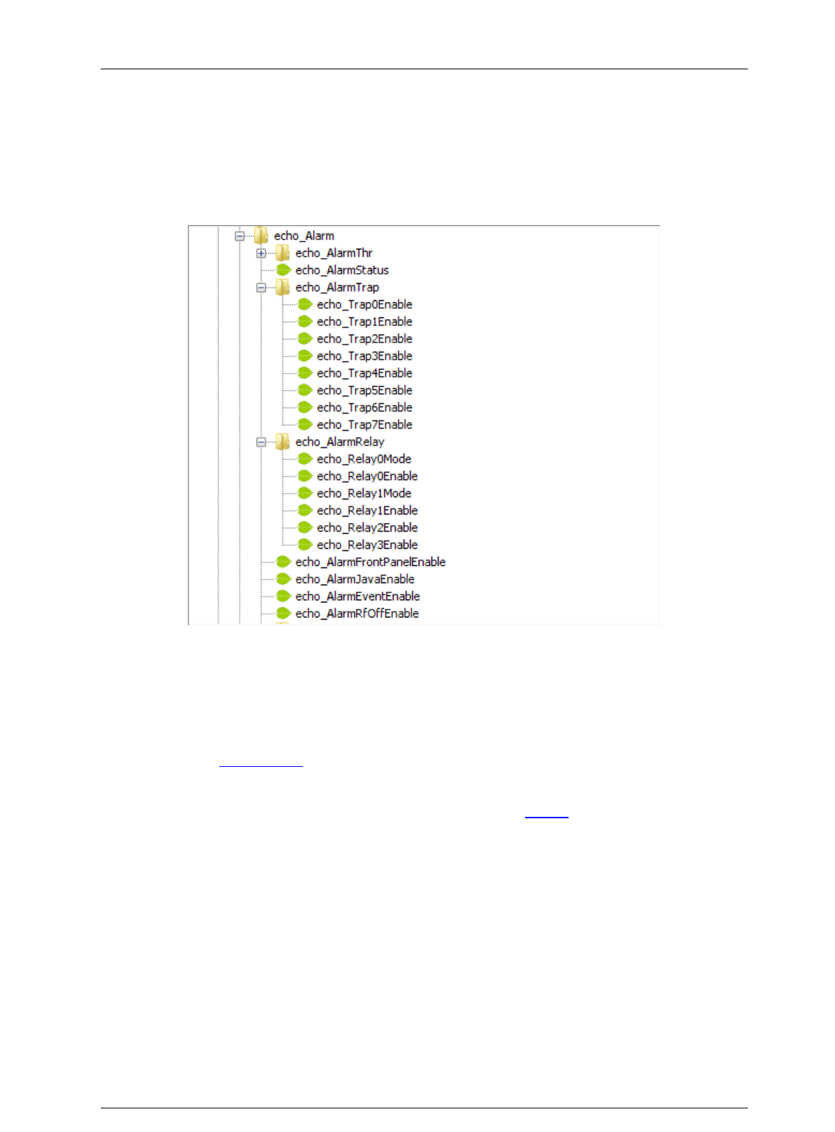
Screen Service SDT ARK 1 ECHO Operations
Jan, 2012 v 1.ATSC_FCC Page 3 - 127
3.18 Configuring alarms masks
The echo_Alarm leaf allows the monitoring of alarms status, the setting of alarm masks and
thresholds.
Use alarm masks to select how and which alarm have to be notified.
Figure 36. Configuring alarms
There are six families of alarm masks:
echo_AlarmJavaEnable: the selected alarms status is notified on the Java alarm
page icon.
echo_AlarmFrontPanelEnable: the selected alarms status is notified on LCD
display lighting the alarm button and listing the alarms in the Alarms menu (refer to
Alarms Menu paragraph).
echo_AlarmEventsEnable: the selected alarms status generate an alarm event
that will be logged in the event memory (refer to Events paragraph).
echo_AlarmRelay: the selected alarms switch-on the corresponding relay.
echo_AlarmTrap: the selected alarms generate the corresponding trap message.
echo_AlarmRfEnable: the selected alarms switch off the RF output. The RF mask
is almost entirely fixed in order to avoid board damages or malfunctioning.
Each alarm mask is a 32 bits word and each alarm represents one bit (0: Off, 1: On). Set the
decimal value corresponding to the mask you want to activate in the relatve leaf. The following
table shows the bit-to-alarm association.

Screen Service SDT ARK 1 ECHO Operations
Jan, 2012 v 1.ATSC_FCC Page 3 - 128
Table 20.
Bit-to-alarm association map
Alarm
Bit
Alarm
Bit
Up converter Osc. Unlock
0
Signal 10 MHz Lock
16
PS Voltage out range
1
Signal 146 MHz Lock
17
PS Current out of range
2
Signal 960 MHz Lock
18
Absolute Power Limiter
3
Down Converter Osc. Unlock
19
Up converter communication error
4
No RF Input
20
Temperature High Alarm
5
RF Input Squelch
21
Temperature Level-3dB
6
RF Digital Ber. Alarm
22
Temperature High Warning
7
File System Error
23
Forward Power High
8
Bad File in File system
24
Forward Power Low Warning
9
1PPS Lock
25
Forward Power Low Alarm
10
PPS Phase
26
Reflex Power High
11
System Delay
27
Fan Speed
12
No MIP
28
S/N Level
13
No Input
29
GPS Lock
14
FPGA Boot alarm
30
GPS Communication Error
15
Warm Up
31
E.g. if you want to enable the No MIP and No Input alarms of a generic alarm mask, set the
decimal value of 805,306,368 that corresponds to a binary value of
0011 0000 0000 0000 0000 0000 0000 0000.
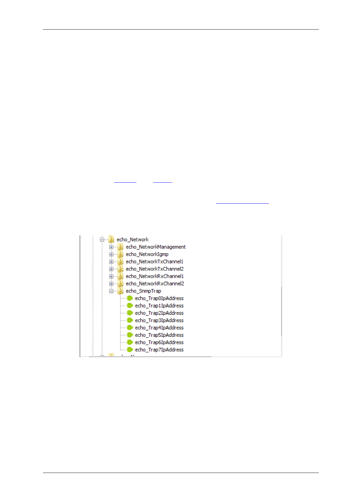
Screen Service SDT ARK 1 ECHO Operations
Jan, 2012 v 1.ATSC_FCC Page 3 - 129
3.19 Traps
While a management station can poll, at fixed time interval, all the agents it knows for some key
information, each agent is responsible for notifying the management station of any alarm
condition. These events are communicated in SNMP messages known as traps.
The following parameters should be set in order to correctly configure traps:
SNMP Agent Port: 162.
SNMP Agent Transport protocol: IP/UDP.
Variable
o OID: 1.3.6.1.4.1.21678.200.13.
o Value(gauge): 32 Bit
3.19.1 Configuring traps
Use Java (refer to Network and Alarms paragraphs for further information) or SNMP user
interfaces to configure traps.
The configuration of traps is performed through the setting of a trap alarm mask, by means of
leaves housed in the echo_AlarmTrap node (refer to Configuring alarms paragraph), and
through the setting of the destination IP Address of the receiving management stations, by
means of leaves housed in the echo_Network node as shown in next figure.
Figure 37. Configuring traps
Figure 38. SNMP Trap Message

Screen Service SDT ARK 1 ECHO Operations
Jan, 2012 v 1.ATSC_FCC Page 3 - 130

Screen Service SDT ARK 1 ECHO Operations
Jan, 2012 v 1.ATSC_FCC Page 3 - 131
Each trap carries a 32 bits word in which each alarm represents one bit (0: Off, 1: On). The
following table shows the bit-to-alarm association.
Table 21.
Bit-to-trap association map
Alarm
Bit
Alarm
Bit
Up converter Osc. Unlock
0
Signal 10 MHz Lock
16
PS Voltage out range
1
Signal 146 MHz Lock
17
PS Current out of range
2
Signal 960 MHz Lock
18
Absolute Power Limiter
3
Down Converter Osc. Unlock
19
Up converter communication error
4
No RF Input
20
Temperature High Alarm
5
RF Input Squelch
21
Temperature Level-3dB
6
RF Digital Ber. Alarm
22
Temperature High Warning
7
File System Error
23
Forward Power High
8
Bad File in File system
24
Forward Power Low Warning
9
1PPS Lock
25
Forward Power Low Alarm
10
PPS Phase
26
Reflex Power High
11
System Delay
27
Fan Speed
12
No MIP
28
S/N Level
13
No Input
29
GPS Lock
14
FPGA Boot alarm
30
GPS Communication Error
15
Warm Up
31
E.g. A trap carring the decimal value 805,306,368 ,corresponding to a binary value of
0011 0000 0000 0000 0000 0000 0000 0000, means No MIP (bit 28) and No Input (bit 29)
alarms raised.
The Community shown in trap messages can be set from Java interface in the Community box
within the Network window (refer to Network paragraph).
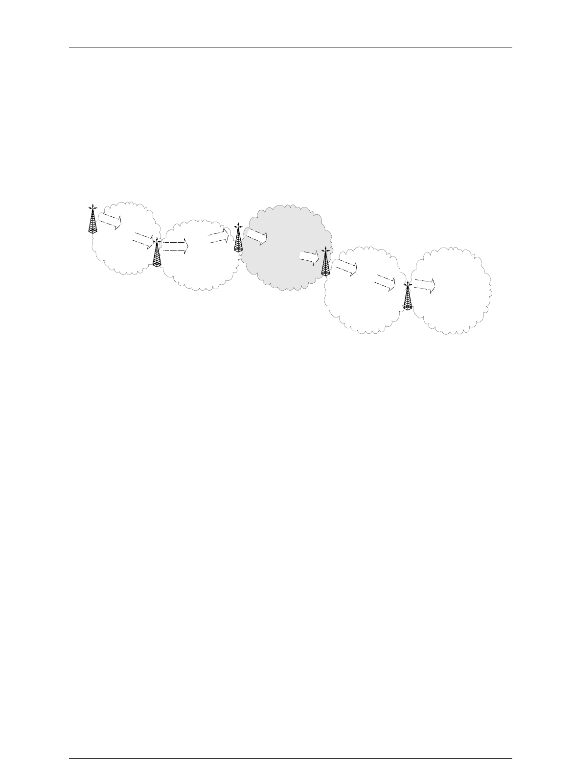
Screen Service SDT ARK 1 ECHO Operations
Jan, 2012 v 1.ATSC_FCC Page 3 - 132
3.20 AUTOMATIC FREQUENCY CONTROL
The Television Broadcasting through countrywide transposers networks requires special care to
avoid too high frequency drift errors.
The Automatic Frequency Control is highly recommended for transposers chains. The following
figure illustrates an example of when the AFC might be used to stop the overwhelming increase
of such errors.
Figure 39. TROVA NOME
The Automatic Frequency Control in ARK1 devices is software defined.
Most of the frequency drift errors could be avoided by means of a stable frequency reference,
such as GPS, but since it is not always available, the ARK1 AFC makes it possible to
compensate frequency jitters owing to each previous transposer.
Frequency compensation of analog input signals is performed through a proprietary algorithm
that, filtering the input video carrier, allows the control loop to extract frequency jitter information
from the input RF phase deviation.
The frequency error adjustment slows down within 3 Hz; it takes about 2 minutes to fulfil the
correction.
Frequency resolution: 1Hz.
Maximum frequency compensation: 4,000,000 Hz.
Frequency compensation of digital input signals is carried out through frequency jitter
information coming from STV0362 receiving the HP Transport Stream.
Frequency resolution: 1kHz.
Maximum frequency compensation: 83kHz.
Due to the Symbol Rate error compensation of the frequency measure algorithm of STV, digital
AFC can work properly only with 0ppm Symbol Rate errors in the input signal.
D
C
A
TX
B
CH 22
CH 22
CH 60: X
CH 36
CH 60: X
CH 36
CH 40
Transposer
Transposer
Teansposer
E
CH 21
Transposer
CH 40

Screen Service SDT ARK 1 ECHO Operations
Jan, 2012 v 1.ATSC_FCC Page 3 - 133
Appendix A. Standalone/Driver working modes
Two different working modes are provided:
Stand-alone: the device works in stand-alone mode. The system configuration can be
totally set through user interfaces. Pre-correction curves are automatically selected
according to channel and power range.
Driver: the device works in a driven system. The system configuration cannot be totally
set through user interfaces. Some settings are disabled on the user interfaces in order
to be driven by serial interface commands. Pre-correction curves are not automatically
selected according to channel and power range, but the selection is manually performed
through serial interface commands.
The following table lists the commands, specific to each system interface, which must be
enabled or disabled while working in Driver mode.
N.B. Diver mode is a specific working mode available and used only in N+1 configuration
systems.

Screen Service SDT ARK 1 ECHO Operations
Jan, 2012 v 1.ATSC_FCC Page 3 - 134
Issue
Ethernet Interface – Port
10001
Java
SNMP
Ethernet
interface
– Port
5000
Char interface
Local
Interface
(Display)
MIP
OPTO
Block
output
channel
setting
Commands: “oo” and “w” uC
registers 0x02 and 0x12
uC ignores the commands
Java
control
is
disabled
SNMP
commands
are
ignored
Not
present
Commands: “O”
or “o” and “W”
or “w” uC
registers 0x02
and 0x12
The control is
enabled
Not
present
Not
present
Not
present
Block
frequency
offset
setting
Commands:
“w” FPGA registers
0x07 up to 0x0A and 0x17 up to
0x1A
uC ignores the command
Java
control
is
disabled
SNMP
commands
are
ignored
Not
present
Commands:
“W” or “w”
FPGA registers
0x07 up to
0x0A and 0x17
up to 0x1A
The control is
enabled
Not
present
Frequency
offset
function is
disabled
from uC
Command:
“W” FPGA
register
0x0020
bit 1=0
Not
present
Block MIP
frequency
offset
setting
Command:
“w” FPGA register 0x0020 bit 1
uC ignores the command
Java
control
is
disabled
SNMP
commands
are
ignored
Not
present
Command:
“w” or “w”
FPGA register
0x0020 bit 1
The control is
enabled
Not
present
Not
present
Block
power
setting
Commands: “op” and “w” uC
registers 0x0C and 0x0B, and
0x1C and 0x1B
uC ignores the command
Java
control
is
disabled
SNMP
commands
are
ignored
Not
present
Command:
“OP” or “op”
and “W” or “w”
uC registers
0x0C and 0x0B,
and 0x1C and
0x1B
The control is
enabled
Not
present
Tx power
function is
disabled
from uC
Command:
“W” FPGA
register
0x0020
bit 2=0
Not
present
Block MIP
TX power
setting
Command:
“W” FPGA register 0x0020 bit 2
uC ignores the command
Java
control
is
disabled
SNMP
commands
are
ignored
Not
present
Command:
“W” or “w”
FPGA register
0x003B bit 2
The control is
enabled
Not
present
Not
present

Screen Service SDT ARK 1 ECHO Operations
Jan, 2012 v 1.ATSC_FCC Page 3 - 135
Issue
Ethernet Interface – Port
10001
Java
SNMP
Ethernet
interface
– Port
5000
Char interface
Local
Interface
(Display)
MIP
OPTO
Block
manual
RF
ON/OFF
command
Command:
“W” uC register 0x26
uC ignores the command
Java
control
is
disabled
SNMP
commands
are
ignored
Not
present
Command:
“W” or “w” uC
register 0x26
The control is
enabled
Not
present
Not
present
OPTO
0=
Closed
Enabled
Block
mode
switch
Commands: “w” uC registers
0x00/0x01/0x10/0x11/0x33/0x32
Java control is disabled
uC ignores the command
Java
controls
are
disabled
SNMP
commands
are
ignored
Not
present
Commands: “W” or “w” uC
registers
0x00/0x01/0x10/0x11/0x33/0x32
The control is enabled
Command
mode
switch
The
command
is
disabled
Tag 33
Function –
Remote
Mode
Switch
Disabled
by uC
Command:
“W” FPGA
register
0x003B
bit 7=0
OPTO
1=
Closed
Disabled
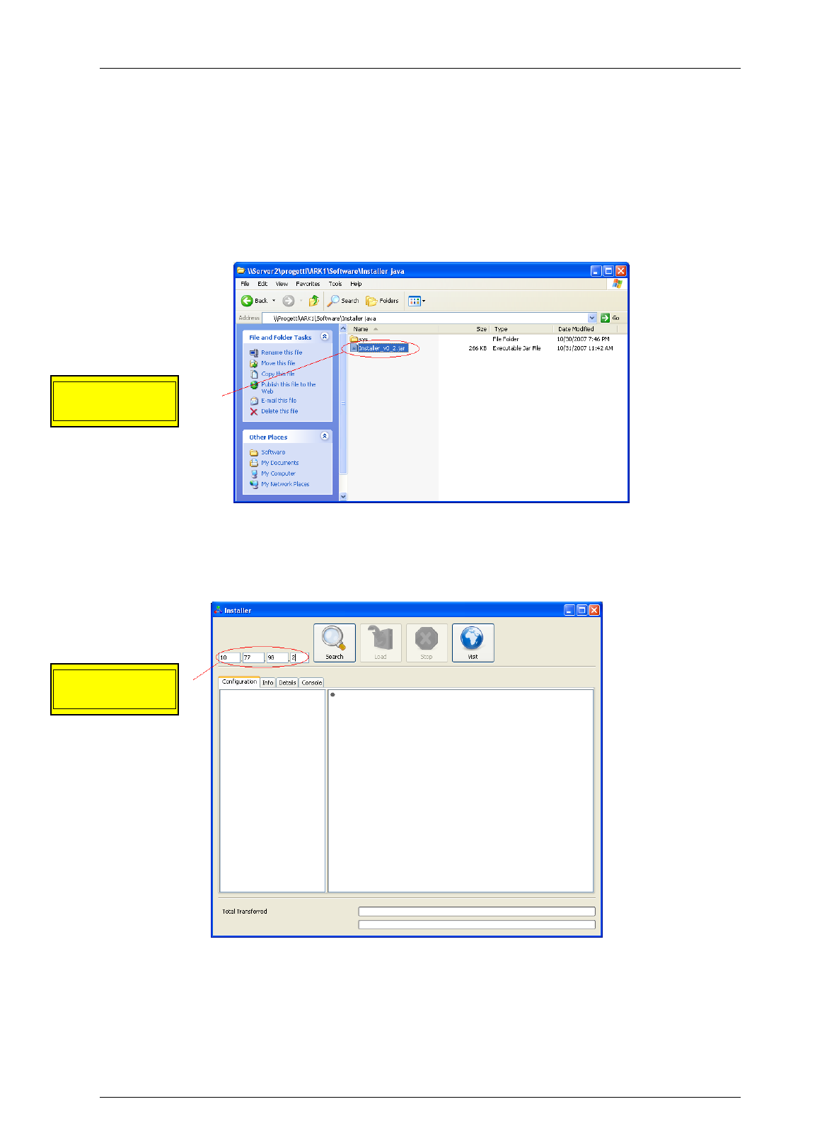
Screen Service SDT ARK 1 ECHO Operations
Jan, 2012 v 1.ATSC_FCC Page 3 - 136
3.21 APPLICATION NOTE 1
3.21.1 How to update
1. Launch the Java installer.
Figure 40. Java Installer
2. Insert the board IP address into the numeric field.
Figure 41. Java Installer - IP Address insertion
Insert the board
IP Address
Launch the
Java Installer
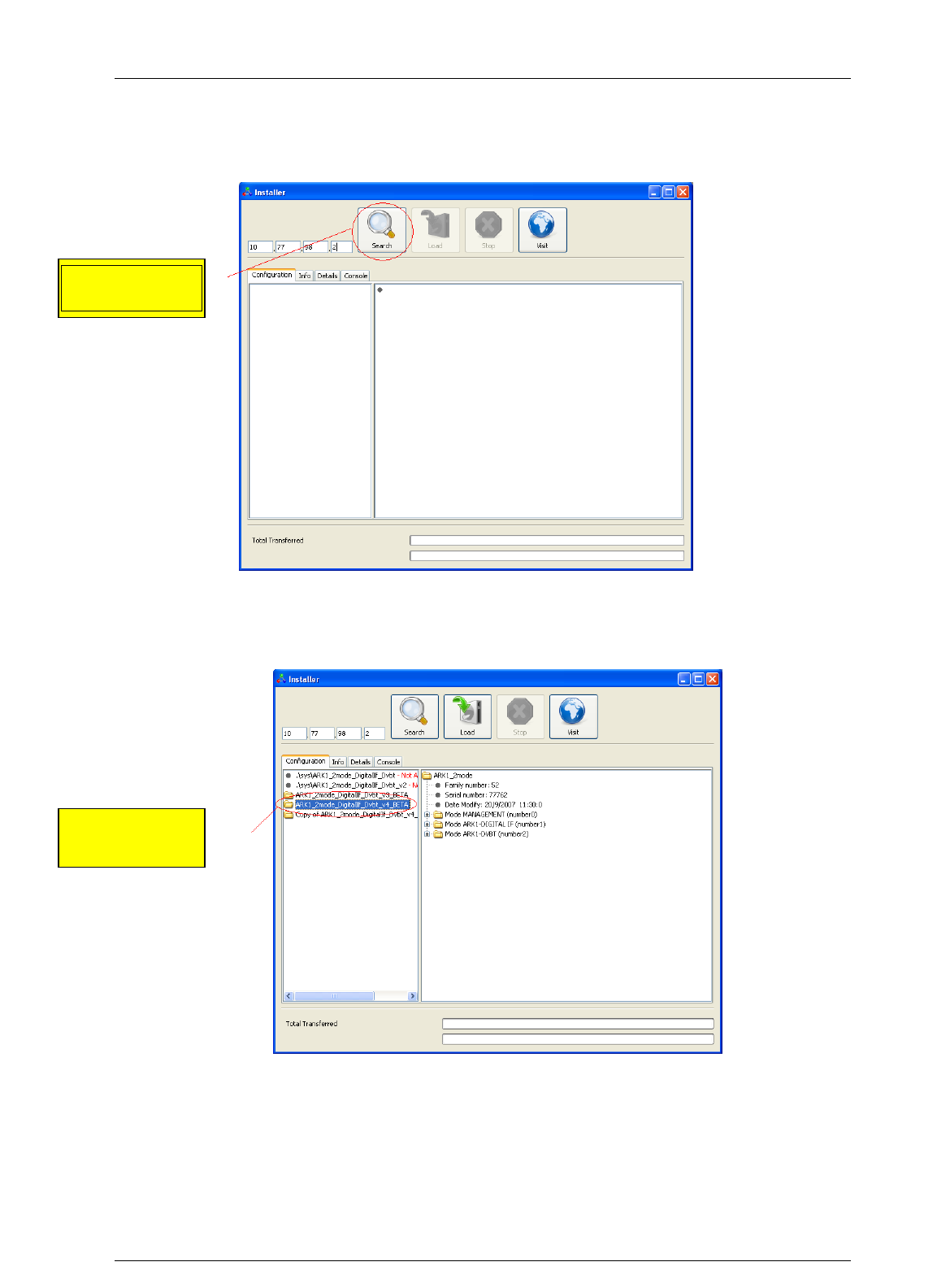
Screen Service SDT ARK 1 ECHO Operations
Jan, 2012 v 1.ATSC_FCC Page 3 - 137
3. Click on the “Search” button.
Figure 42. Java Installer - Search button
4. Select the device version you want to load.
Figure 43. Java Installer - Device Version Selection
Click on the
“Search” button
Select the
version
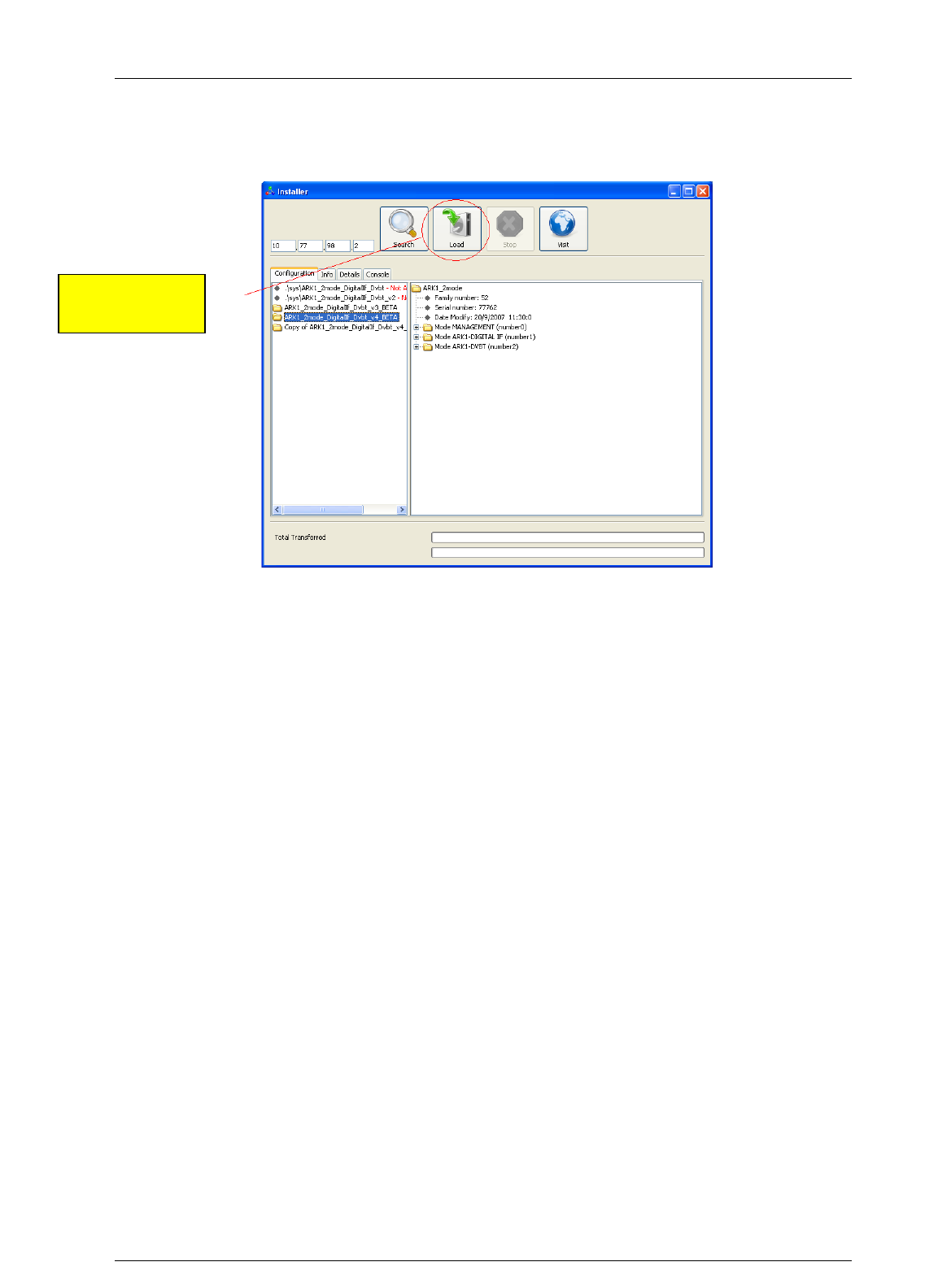
Screen Service SDT ARK 1 ECHO Operations
Jan, 2012 v 1.ATSC_FCC Page 3 - 138
5. Click on the “Load” button.
Figure 44. Java Installer - Load button
Click on the
“Load” button
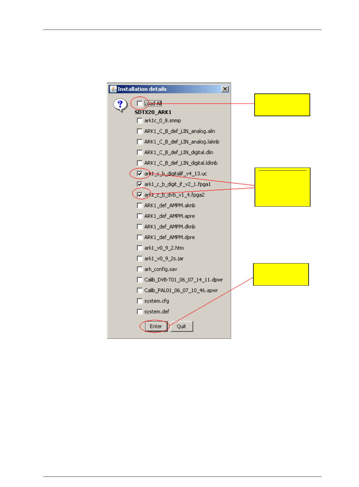
Screen Service SDT ARK 1 ECHO Operations
Jan, 2012 v 1.ATSC_FCC Page 3 - 139
6. If you want to update only some software versions, click on the check boxes
corresponding to the software version you want to load, otherwise click on the check
box corresponding to the Load All option. Click on the “Enter” button to start the loading.
Figure 45. Java Installer - Software versions selection
Select the
“Load All” option
Select one by
one the software
versions you
want to load
Click on the
“Enter” button
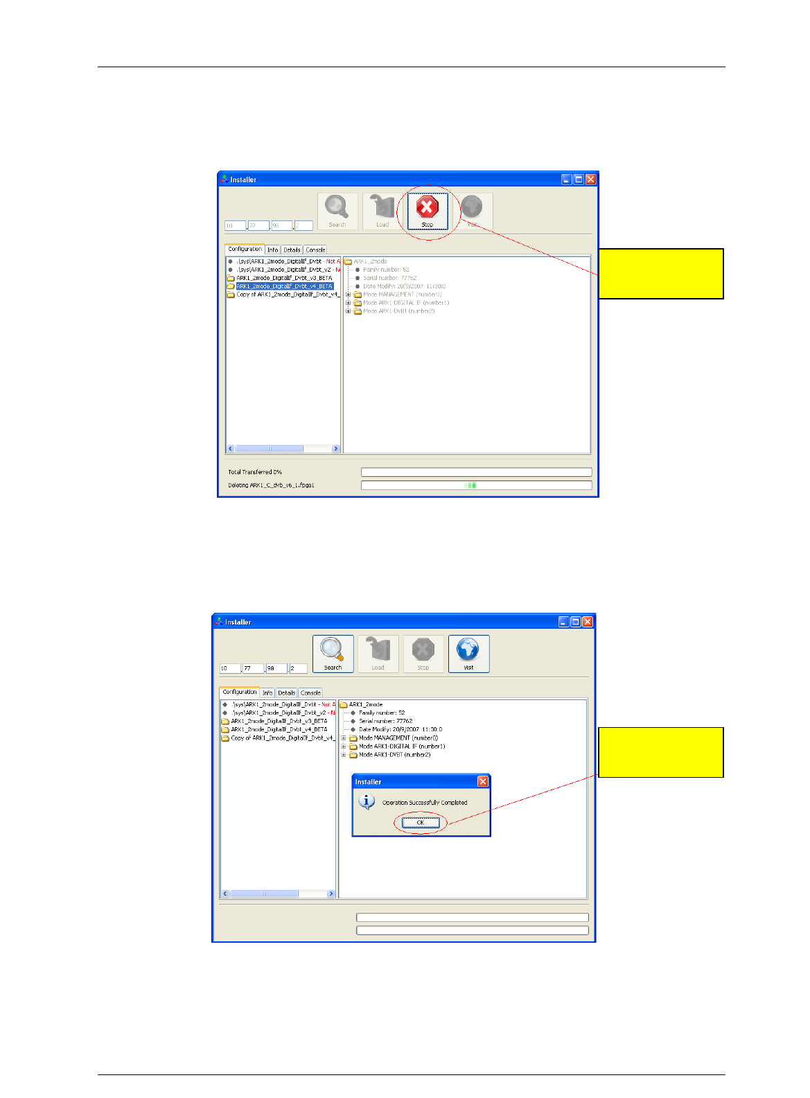
Screen Service SDT ARK 1 ECHO Operations
Jan, 2012 v 1.ATSC_FCC Page 3 - 140
7. Once started the loading, the “Stop” button lights up. Click on this button to end the
programming.
Figure 46. Java Installer - Stop button
8. When the loading is complete, the pop-up window “Operation Successfully Completed”
appears. Click on the “OK” button.
Figure 47. Java Installer - Operation Successfully Completed
3.22 Java Virtual Machine
The Java interface requires a host computer connected via Ethernet to the board with the proper
Java Machine version installed.
Click on the
“Stop” button
Click on the
“OK” button
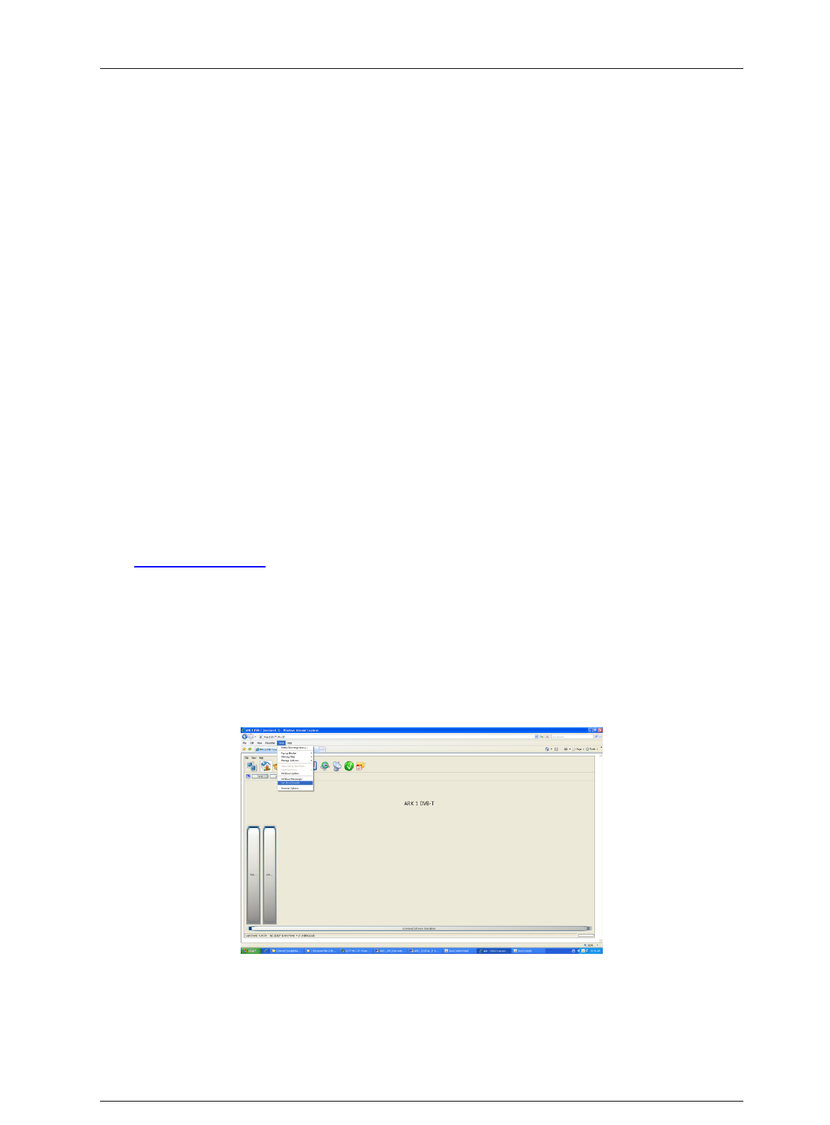
Screen Service SDT ARK 1 ECHO Operations
Jan, 2012 v 1.ATSC_FCC Page 3 - 141
3.23 ETHERNET CONNECTION
The host computer has to be connected via Ethernet to the board.
Direct or crossed UTP category 6 cable is recommended.
3.23.1 Configuration
In order to connect to the board trough a LAN, all the devices have to be on the same network.
The default IP address settings of the X-port are:
IP address: 10.77.xx.xx , where xx is the host address unique for each board.
Subnet mask: 255.255.0.0 .
Remember to change these settings if they are not compatible with the LAN where the computer
and the board are connected.
IP address and network parameters can be changed only using the local interface. Please refer
to chapter 6 for the network setting commands.
3.23.2 Java(TM) Platform
3.23.3 Download
The Java Interface works with any Sun Java Virtual Machine after the 1.4.1 version.
If the computer has no Java Virtual Machine installed, the recommended 1.5.0 version can be
downloaded from the Sun Server trough this link:
http://www.java.com/.
3.23.4 Java Control Panel
Java caching must be disabled; to do that follow the following steps:
1. Open Internet Explorer, click on Tool button and select the Sun Java Console option.
Figure 48. Sun Java Console
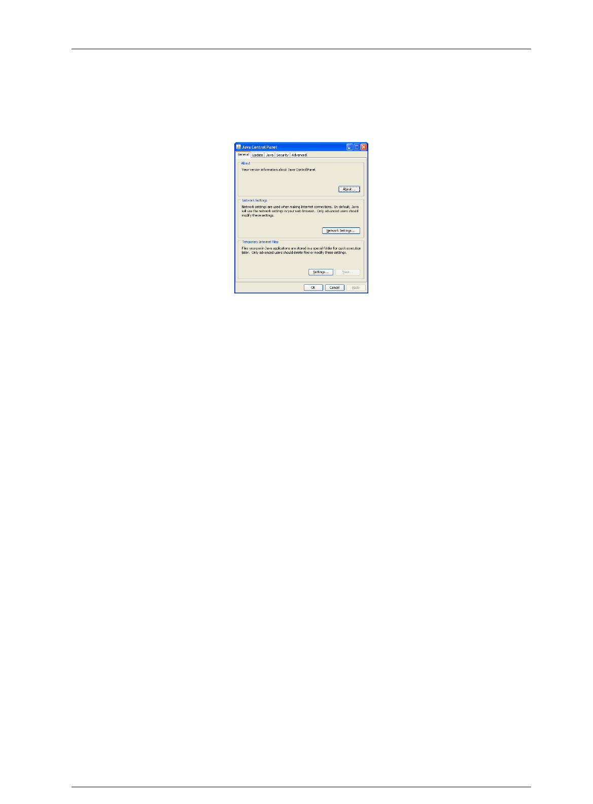
Screen Service SDT ARK 1 ECHO Operations
Jan, 2012 v 1.ATSC_FCC Page 3 - 142
2. Perform a right button mouse click on the Java(TM) Platform icon sited on the right
corner of the Taskbar and select “Open Control Panel”. The following window will
suddenly appear.
Figure 49. Java Control Panel
3. Select “Settings…” in the “Temporary Internet Files” section of the “General” tab.
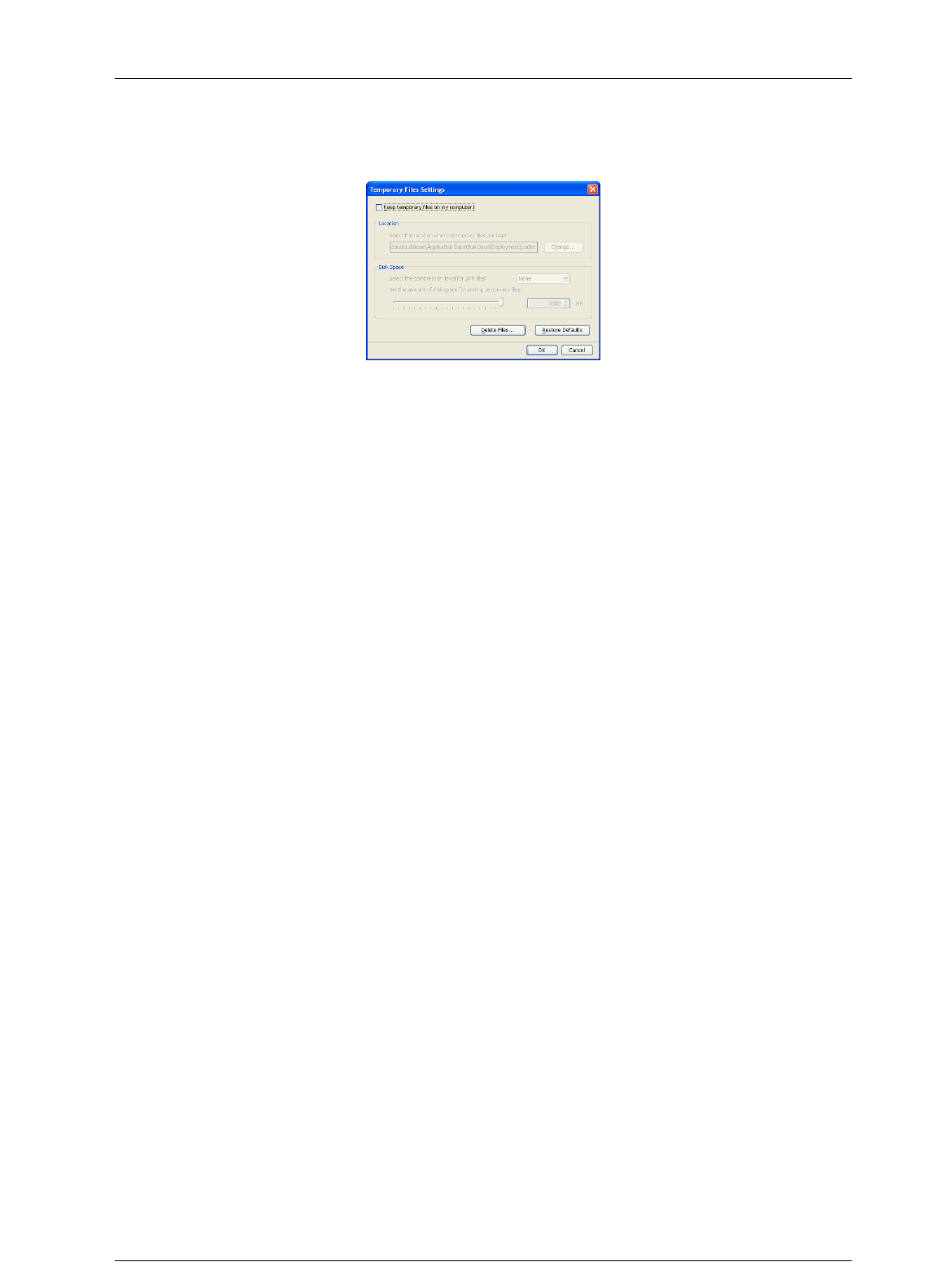
Screen Service SDT ARK 1 ECHO Operations
Jan, 2012 v 1.ATSC_FCC Page 3 - 143
4. Deselect the check box of the “Keep temporary files on my computer” (disable cache).
Figure 50. Temporary Files Settings
5. Push “OK” button and close the window.
3.24 SUPPORTED WEB BROWSERS
The Java GUI is designed to support every Web Browser that uses Sun Java Virtual Machine
from 1.4.1 and newer.
Here’s a list of Web Browsers where Java GUI has been tested and troubleshot:
Microsoft Internet Explorer, version 5 and newer.
Mozilla Firefox, version 1.5 and newer.