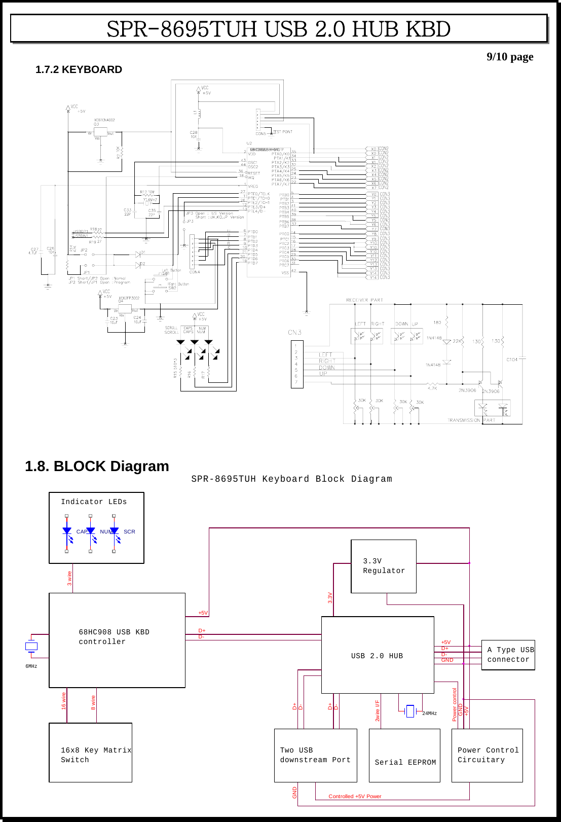
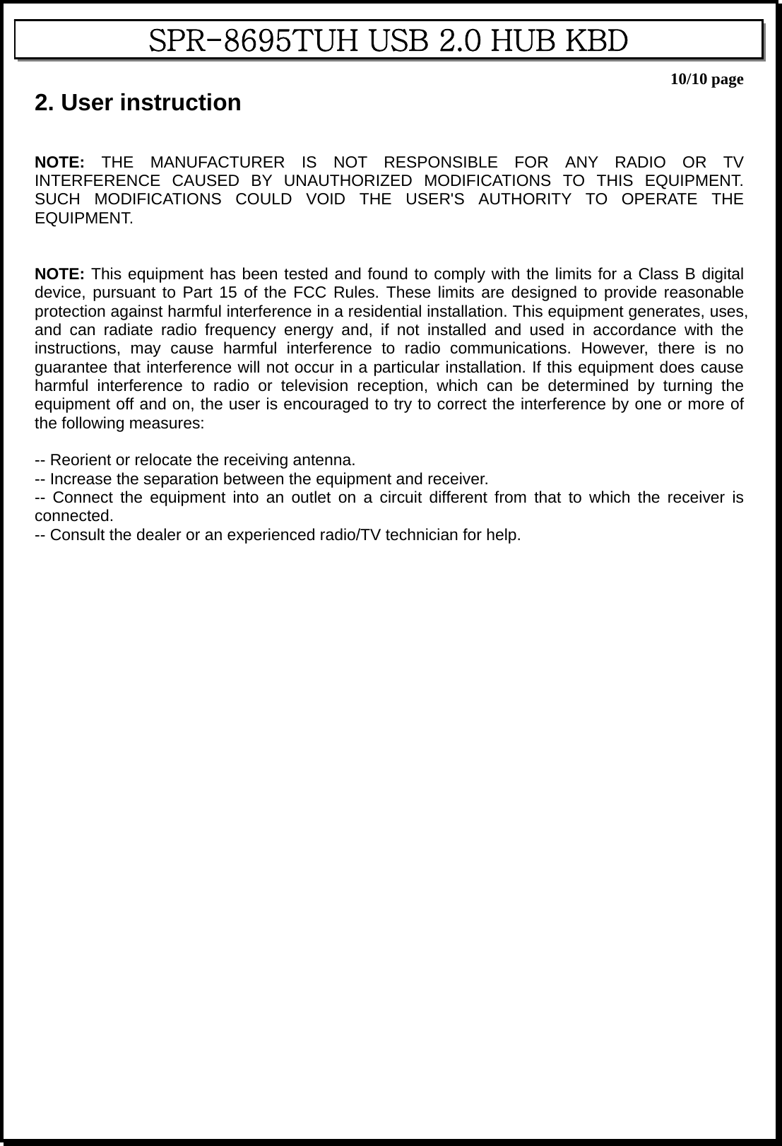
Se Jin Electron SPR-8695TUH KEYBOARD User Manual USERS MANUAL
Se Jin Electron Inc KEYBOARD USERS MANUAL
UserManual.wiki
>
Se Jin Electron
>
SPR 8695TUH User Manual
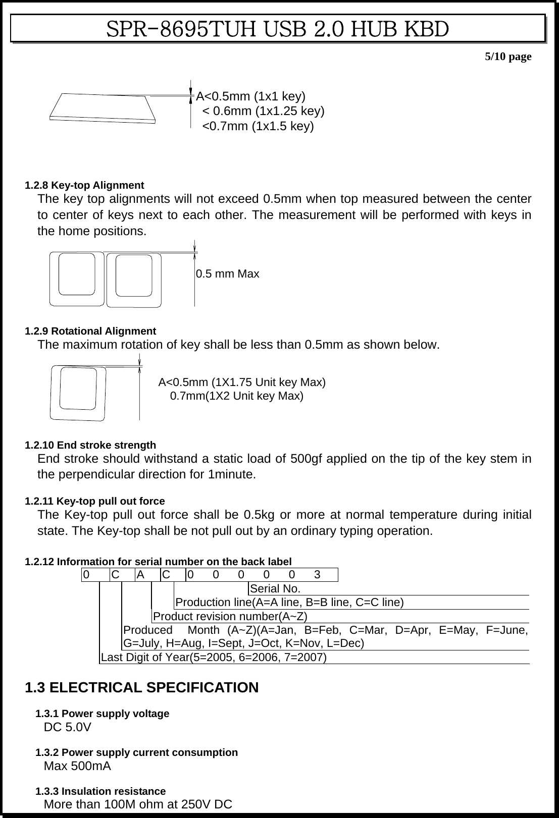
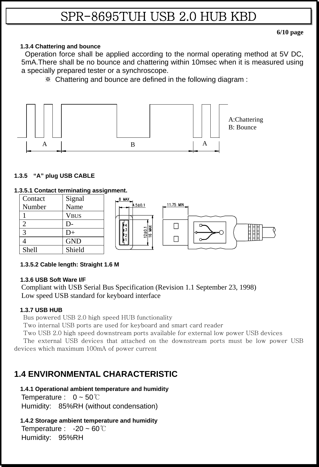
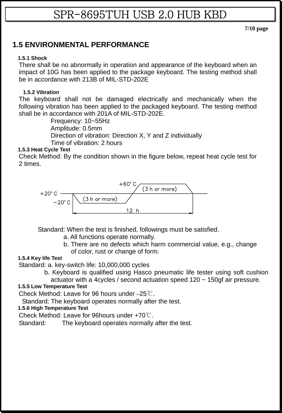
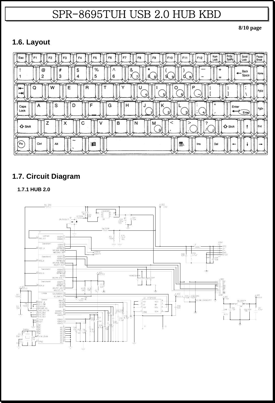
USERS MANUAL
Navigation menu
Upload a User Manual
Namespaces
Wiki Guide
HTML
PDF
Info
Views
User Manual
Discussion / Help
Navigation