Se Jin Electron SPR-8695TUH KEYBOARD User Manual USERS MANUAL
Se Jin Electron Inc KEYBOARD USERS MANUAL
USERS MANUAL
1/10 page
SPR-8695TUH USB 2.0 HUB KBD
User’s Manual
자료번호: RD-071008-2
■ MODEL NAME: SPR-8695TUH
■ TYPE NAME: USB wired mini track-ball keyboard with high speed HUB
■ Product CODE: 903U02210101
작 성 일: Oct. 08, 2007
작성부서: 기술연구소
작 성 자: 김 쌍 진 (Ms. SsangJin Kim)
작 성 검 토 승 인
결
재
SEJIN ELECTRON INC.

2/10 page
SPR-8695TUH USB 2.0 HUB KBD
CONTENTS
1. SPECIFICATION..................................................................................... 3
1.1 SCOPE ..............................................................................................................3
1.2. MECHANICAL PECIFICATION..........................................................................3
1.2.1 Key switch...............................................................................................................3
1.2.2 Key switch Operation...............................................................................................3
1.2.3 Operating Region ....................................................................................................4
1.2.4 Key-top Deflection ...................................................................................................4
1.2.5 Operating feeling .....................................................................................................4
1.2.6 Key-top Height Variation ..........................................................................................4
1.2.7 Tilt...........................................................................................................................4
1.2.8 Key-top Alignment ...................................................................................................5
1.2.9 Rotational Alignment................................................................................................5
1.2.10 End stroke strength................................................................................................5
1.2.11 Key-top pull out force .............................................................................................5
1.2.12 Information for serial number on the back label ......................................................5
1.3 ELECTRICAL SPECIFICATION..........................................................................5
1.3.1 Power supply voltage...............................................................................................5
1.3.2 Power supply current consumption ..........................................................................5
1.3.3 Insulation resistance................................................................................................5
1.3.4 Chattering and bounce ............................................................................................6
1.3.5 “A” plug USB CABLE ............................................................................................6
1.3.6 USB Soft Ware I/F ...................................................................................................6
1.3.7 USB HUB ................................................................................................................6
1.4 ENVIRONMENTAL CHARACTERISTIC..............................................................6
1.4.1 Operational ambient temperature and humidity ........................................................6
1.4.2 Storage ambient temperature and humidity..............................................................6
1.5 ENVIRONMENTAL PERFORMANCE .................................................................7
1.5.1 Shock......................................................................................................................7
1.5.2 Vibration..................................................................................................................7
1.5.3 Heat Cycle Test .......................................................................................................7
1.5.4 Key life Test.............................................................................................................7
1.5.5 Low Temperature Test..............................................................................................7
1.5.6 High Temperature Test.............................................................................................7
1.6. Layout ..............................................................................................................8
1.7. Circuit Diagram................................................................................................8
1.7.1 HUB 2.0 ..................................................................................................................8
1.7.2 KEYBOARD ............................................................................................................9
1.8. BLOCK Diagram...............................................................................................9
2. User instruction .................................................................................. 10

3/10 page
SPR-8695TUH USB 2.0 HUB KBD
1. SPECIFICATION
1.1 SCOPE
This document describes the detail specifications for “SEJIN STD” TrackBall USB
keyboard
1.2. MECHANICAL PECIFICATION
1.2.1 Key switch
Operating system: non-lock RUBBER tactile feeling.
Travel amount : 3.5±0.5mm with measuring load of 200gf applied.
Operating force : 55±25 gf
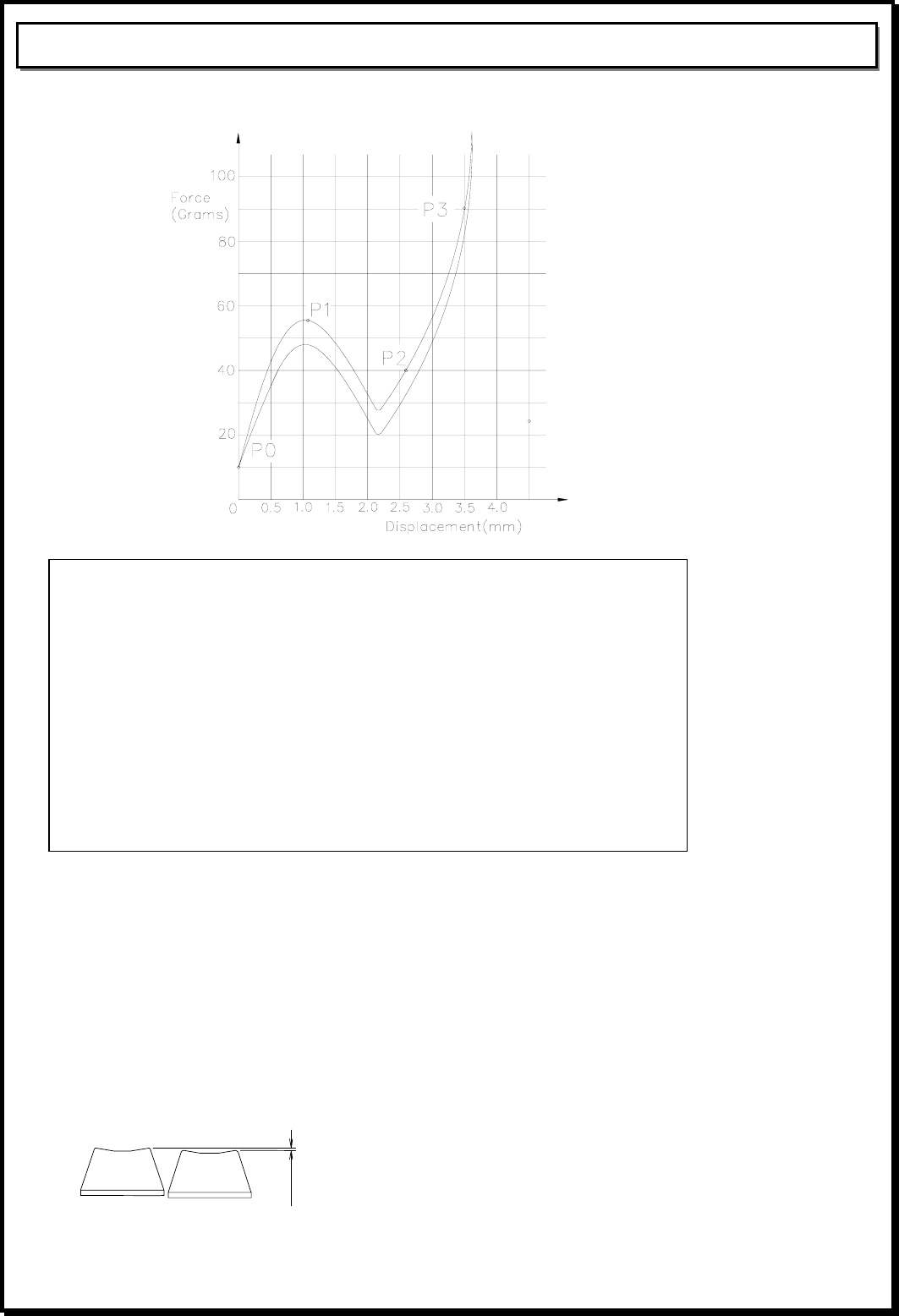
1.2.2 Key switch Operation
Key switch operating parameters should comply with those listed below.
Figure on the below represents typical pressure force and displacement values
acceptable to SEJIN. The force/displacement curve should not exhibit any significant
step or plateau from P2 to the end of full travel. Linear measures are in mm and the
values represent the force and displacement of a key switch after it has been preloaded
by 10 to 20 grams.
Standard: a. Non-lock rubber tactile feeling
b. P0 (Preloaded Point)
Travel = 0 mm / Force = 10 +10/-5 grams
c. P1 (Break over Point)
Travel = 1.15 ± 0.25 mm / Force = 60 ± 20 grams
d. P2 (Make Point)
Travel = 2.66 ± 0.25 mm / Force = P1 - Delta
Delta = 45% to 60% of the P1 force, but 20 grams minimum.
e. P3 (Normally End Point)
Travel = 3.8 ± 0.5 mm / Force = P1 + 10 to 15 grams
f. Total Displacement at 100 grams
Minimum = 3.2 mm, Nominal = 3.5 mm, Maximum = 4.8 mm
Check Point: a. Operating feeling: No definite stickiness or other abnormality shall be
allowed. When force is applied with a finger on the key-top center
at the rate of three times a second.
b. Key-top pulling strength: A key-top should come off after applying a
force of 0.5Kg to 8Kg range in the vertical direction.
4/10 page
SPR-8695TUH USB 2.0 HUB KBD
1.2.3 Operating Region
1.2.4 Key-top Deflection
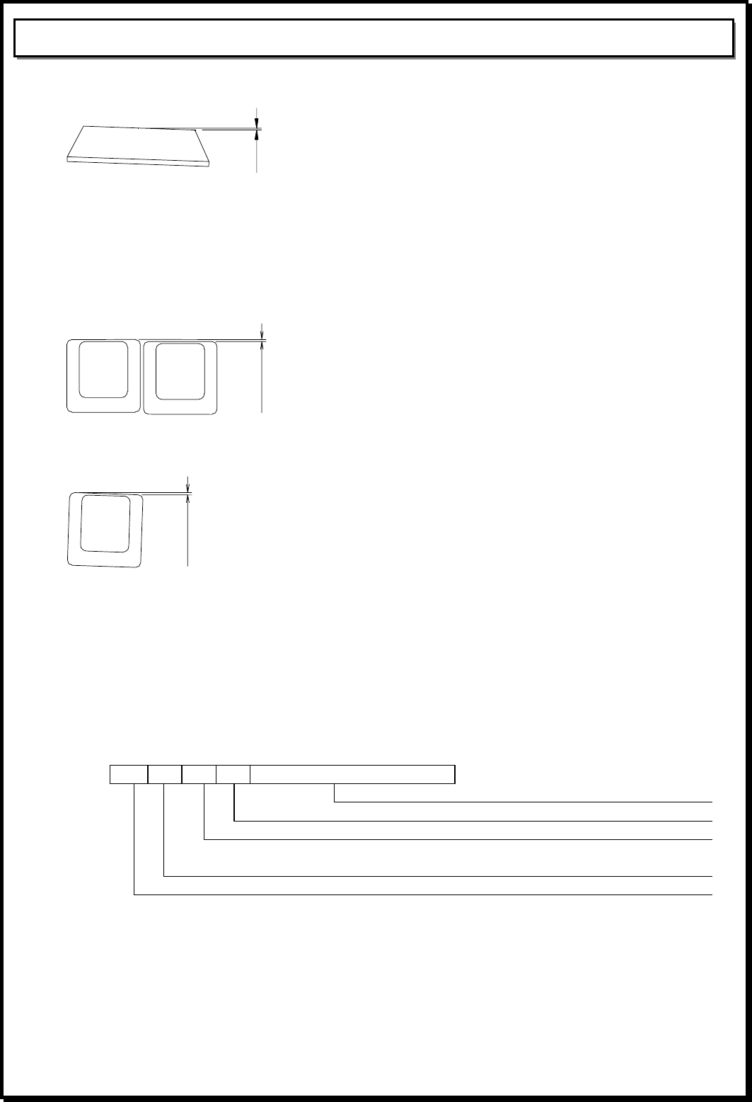
Key-top deflection to on side shall be 0.8mm or less.
1.2.5 Operating feeling
No definite stickiness or other abnormality shall be allowed when force is applied with a
finger to Key-top center at the rate of 3 times a second.
1.2.6 Key-top Height Variation
The key top height variation must not greater than 0.5mm when measured between the
center to center of keys next to each other. The measurement will be performed with
keys in the home positions.
0.5mm Max
1.2.7 Tilt
The keys must not exhibit tilt greater than 0.5mm.for the 1x1 key top, 0.6mm for the
1x1.25 key top and 0.7mm for the 1x1.5 key
5/10 page
SPR-8695TUH USB 2.0 HUB KBD
A<0.5mm (1x1 key)
< 0.6mm (1x1.25 key)
<0.7mm (1x1.5 key)
1.2.8 Key-top Alignment
The key top alignments will not exceed 0.5mm when top measured between the center
to center of keys next to each other. The measurement will be performed with keys in
the home positions.
0.5 mm Max
1.2.9 Rotational Alignment
The maximum rotation of key shall be less than 0.5mm as shown below.
A
<0.5mm (1X1.75 Unit key Max)
0.7mm(1X2 Unit key Max)
1.2.10 End stroke strength
End stroke should withstand a static load of 500gf applied on the tip of the key stem in
the perpendicular direction for 1minute.
1.2.11 Key-top pull out force
The Key-top pull out force shall be 0.5kg or more at normal temperature during initial
state. The Key-top shall be not pull out by an ordinary typing operation.
1.2.12 Information for serial number on the back label
0 C A C 0 0 0 0 0 3
Serial No.
Production line(A=A line, B=B line, C=C line)
Product revision number(A~Z)
Produced Month (A~Z)(A=Jan, B=Feb, C=Mar, D=Apr, E=May, F=June,
G=July, H=Aug, I=Sept, J=Oct, K=Nov, L=Dec)
Last Digit of Year(5=2005, 6=2006, 7=2007)
1.3 ELECTRICAL SPECIFICATION
1.3.1 Power supply voltage
DC 5.0V
1.3.2 Power supply current consumption
Max 500mA
1.3.3 Insulation resistance
More than 100M ohm at 250V DC
6/10 page
SPR-8695TUH USB 2.0 HUB KBD
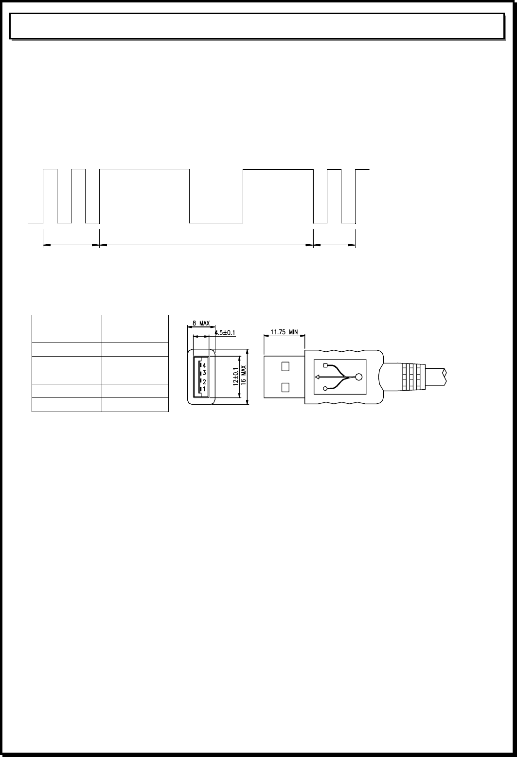
1.3.4 Chattering and bounce
Operation force shall be applied according to the normal operating method at 5V DC,
5mA.There shall be no bounce and chattering within 10msec when it is measured using
a specially prepared tester or a synchroscope.
※ Chattering and bounce are defined in the following diagram :
A:Chattering
B: Bounce
A
B
A
1.3.5 “A” plug USB CABLE
1.3.5.1 Contact terminating assignment.
Contact
Number Signal
Name
1 VBUS
2 D-
3 D+
4 GND
Shell Shield
1.3.5.2 Cable length: Straight 1.6 M
1.3.6 USB Soft Ware I/F
Compliant with USB Serial Bus Specification (Revision 1.1 September 23, 1998)
Low speed USB standard for keyboard interface
1.3.7 USB HUB
Bus powered USB 2.0 high speed HUB functionality
Two internal USB ports are used for keyboard and smart card reader
Two USB 2.0 high speed downstream ports available for external low power USB devices
The external USB devices that attached on the downstream ports must be low power USB
devices which maximum 100mA of power current
1.4 ENVIRONMENTAL CHARACTERISTIC
1.4.1 Operational ambient temperature and humidity
Temperature : 0 ~ 50℃
Humidity: 85%RH (without condensation)
1.4.2 Storage ambient temperature and humidity
Temperature : -20 ~ 60℃
Humidity: 95%RH
7/10 page
SPR-8695TUH USB 2.0 HUB KBD
1.5 ENVIRONMENTAL PERFORMANCE
1.5.1 Shock
There shall be no abnormally in operation and appearance of the keyboard when an
impact of 10G has been applied to the package keyboard. The testing method shall
be in accordance with 213B of MIL-STD-202E
1.5.2 Vibration
The keyboard shall not be damaged electrically and mechanically when the
following vibration has been applied to the packaged keyboard. The testing method
shall be in accordance with 201A of MIL-STD-202E.
Frequency: 10~55Hz
Amplitude: 0.5mm
Direction of vibration: Direction X, Y and Z individually
Time of vibration: 2 hours
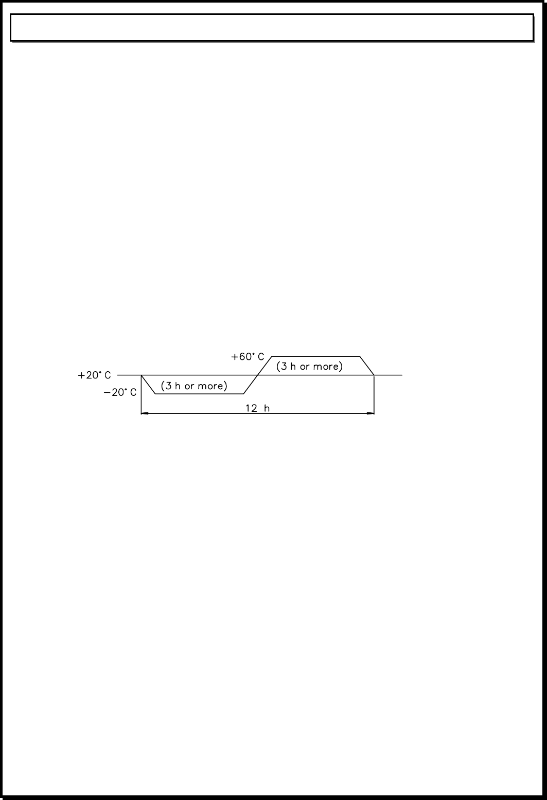
1.5.3 Heat Cycle Test
Check Method: By the condition shown in the figure below, repeat heat cycle test for
2 times.
Standard: When the test is finished, followings must be satisfied.
a. All functions operate normally.
b. There are no defects which harm commercial value, e.g., change
of color, rust or change of form.
1.5.4 Key life Test
Standard: a. key-switch life: 10,000,000 cycles
b. Keyboard is qualified using Hasco pneumatic life tester using soft cushion
actuator with a 4cycles / second actuation speed 120 ~ 150gf air pressure.
1.5.5 Low Temperature Test
Check Method: Leave for 96 hours under –25℃.
Standard: The keyboard operates normally after the test.
1.5.6 High Temperature Test
Check Method: Leave for 96hours under +70℃.
Standard: The keyboard operates normally after the test.
8/10 page
SPR-8695TUH USB 2.0 HUB KBD
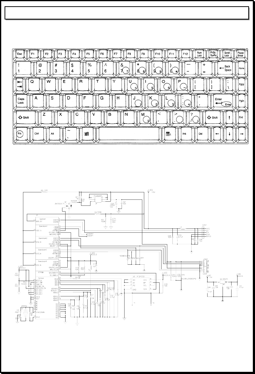
1.6. Layout
1.7. Circuit Diagram
1.7.1 HUB 2.0
9/10 page
SPR-8695TUH USB 2.0 HUB KBD
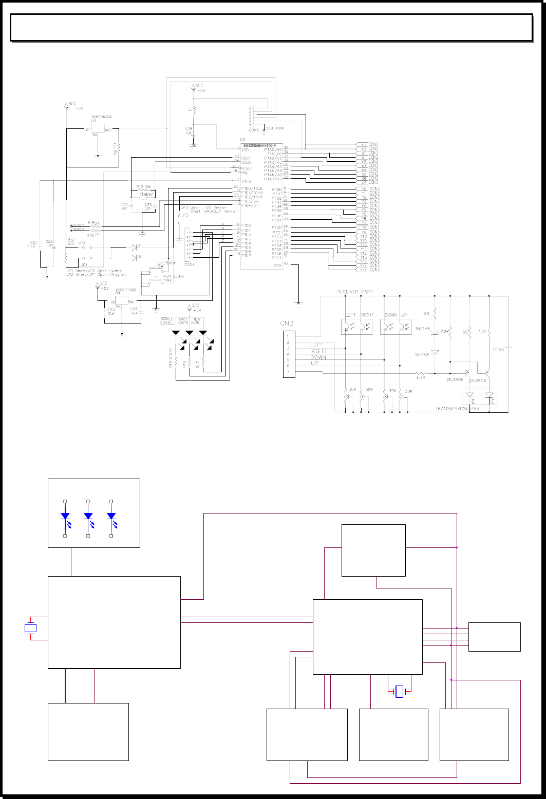
1.7.2 KEYBOARD
1.8. BLOCK Diagram
GND
GND
68HC908 USB KBD
controller
2wire I/F
NUM SCR
3.3V
3.3V
Regulator
USB 2.0 HUB
D-
Indicator LEDs
16x8 Key Matrix
Switch Serial EEPROM
SPR-8695TUH Keyboard Block Diagram
3 wire
CAP
8 wire
D-
D+
D+
A Type USB
connector
24MHz
+5V
6MHz
+5V
D-
D+
D-
Two USB
downstream Port
16 wire
D+
+5V
GND
Controlled +5V Power
Power Control
Circuitary
Power control

10/10 page
SPR-8695TUH USB 2.0 HUB KBD
2. User instruction
NOTE: THE MANUFACTURER IS NOT RESPONSIBLE FOR ANY RADIO OR TV
INTERFERENCE CAUSED BY UNAUTHORIZED MODIFICATIONS TO THIS EQUIPMENT.
SUCH MODIFICATIONS COULD VOID THE USER'S AUTHORITY TO OPERATE THE
EQUIPMENT.
NOTE: This equipment has been tested and found to comply with the limits for a Class B digital
device, pursuant to Part 15 of the FCC Rules. These limits are designed to provide reasonable
protection against harmful interference in a residential installation. This equipment generates, uses,
and can radiate radio frequency energy and, if not installed and used in accordance with the
instructions, may cause harmful interference to radio communications. However, there is no
guarantee that interference will not occur in a particular installation. If this equipment does cause
harmful interference to radio or television reception, which can be determined by turning the
equipment off and on, the user is encouraged to try to correct the interference by one or more of
the following measures:
-- Reorient or relocate the receiving antenna.
-- Increase the separation between the equipment and receiver.
-- Connect the equipment into an outlet on a circuit different from that to which the receiver is
connected.
-- Consult the dealer or an experienced radio/TV technician for help.