Sears 139 53962Srt1 Users Manual
1021499A 1021499A CRAFTSMAN GARAGE DOOR OPENER^ - Manuals and Guides L0303178 View the owners manual for your CRAFTSMAN GARAGE DOOR OPENER^ #1021499A. Home:Garage Door & Opener Parts:Craftsman Parts:Craftsman GARAGE DOOR OPENER^ Manual
CRAFTSMAN Garage Door Opener Manual L0303178 CRAFTSMAN Garage Door Opener Owner's Manual, CRAFTSMAN Garage Door Opener installation guides
139.53975SRT1 L0303178
139.53962SRT1 to the manual 3b6c8b36-8ad3-fae4-85e8-5c718e27d2fa
2015-02-05
: Sears Sears-139-53962Srt1-Users-Manual-399022 sears-139-53962srt1-users-manual-399022 sears pdf
Open the PDF directly: View PDF ![]() .
.
Page Count: 76
Owner's Manual/Manual Del Propietario
1/2 HP
GARAGE DOOR OPENER
ABRIDOR DE PUERTA DE COCHERA
For Residential Use Only/Sblo para uso residencial
Models/Modelos •139.53975SRT1 •139.53962SRT1
Read and follow all safety rules
and operating instructions before
first use of this product.
Fasten the manual near the garage
door after installation.
Leer y seguir todas las reglas de
seguridad y las instrucciones de
operacibn antes de usar este
producto por primera vez.
Guardar este manual cerca de la
puerta de la cochera.
Periodic checks of the opener are
required to ensure safe operation.
Se deben realizar revisiones
peribdicas del abridor de puertas
para asegurar su operacibn
segura.
Sears, Roebuck and Co., Hoffman Estates, IL 60179 U.S.A
www.sears.com/craftsman
TABLE OF CONTENTS
Introduction 2.7
Safety symbol and signal word review ........................ 2
Preparing your garage door ........................................ 3
Tools needed ............................................................... 3
Planning .................................................................. 4-5
Carton inventory .......................................................... 6
Hardware inventory ..................................................... 7
Assembly 8-11
Assemble the rail and install trolley ............................. 8
Fasten rail to motor unit and install idler pulley .......... 9
Install chain/cable and attach sprocket cover ........... 10
Tighten the chain ....................................................... 11
Installation 11.27
Installation safety instructions.................................... 11
Determine the header bracket location ................ 12-13
Install the header bracket .......................................... 14
Attach the rail to the header bracket ......................... 15
Position the opener ................................................... 16
Hang the opener ....................................................... 17
Install the door control ............................................... 18
Install the lights and lens ........................................... 19
Attach the emergency release rope and handle ....... 19
Electrical requirements .............................................. 20
Install the safety reversing sensor ....................... 21-23
Fasten the door bracket ....................................... 24-25
Connect the door arm to the trolley ..................... 26-27
Adjustment 28-30
Adjust the travel limits ............................................... 28
Adjust the force ......................................................... 29
Test the safety reversal system ................................. 30
Test the safety reversing sensor ............................... 30
Operation 31.34
Operation safety instructions..................................... 31
Using your garage door opener ................................ 31
Using the wall-mounted Door Control ....................... 32
To open the door manually ........................................ 32
Care of your garage door opener .............................. 33
Having a problem? .................................................... 34
Programming 35-36
To add a hand-held remote control ........................... 35
To erase all codes ..................................................... 35
3-Function Remotes .................................................. 35
To add or change a Keyless Entry PIN ..................... 36
Repair Parts 37.38
Rail assembly parts ................................................... 37
Installation parts ........................................................ 37
Motor unit assembly parts ......................................... 38
Accessories 39
Warranty
Service Numbers
39
Back cover
INTRODUCTION
Safety Symbol
and Signal Word Review
This garage door opener has been designed and tested to offer safe service provided it is installed, operated,
maintained and tested in strict accordance with the instructions and warnings contained in this manual.
Mechanical
Electrical
When you see these Safety Symbols and Signal
Words on the following pages, they will alert you to
the possibility of serious injury or death if you do
not comply with the warnings that accompany them.
The hazard may come from something mechanical
or from electric shock. Read the warnings carefully.
When you see this Signal Word on the following
pages, it will alert you to the possibility of damage to
your garage door and/or the garage door opener if
you do not comply with the cautionary statements
that accompany it. Read them carefully.
2
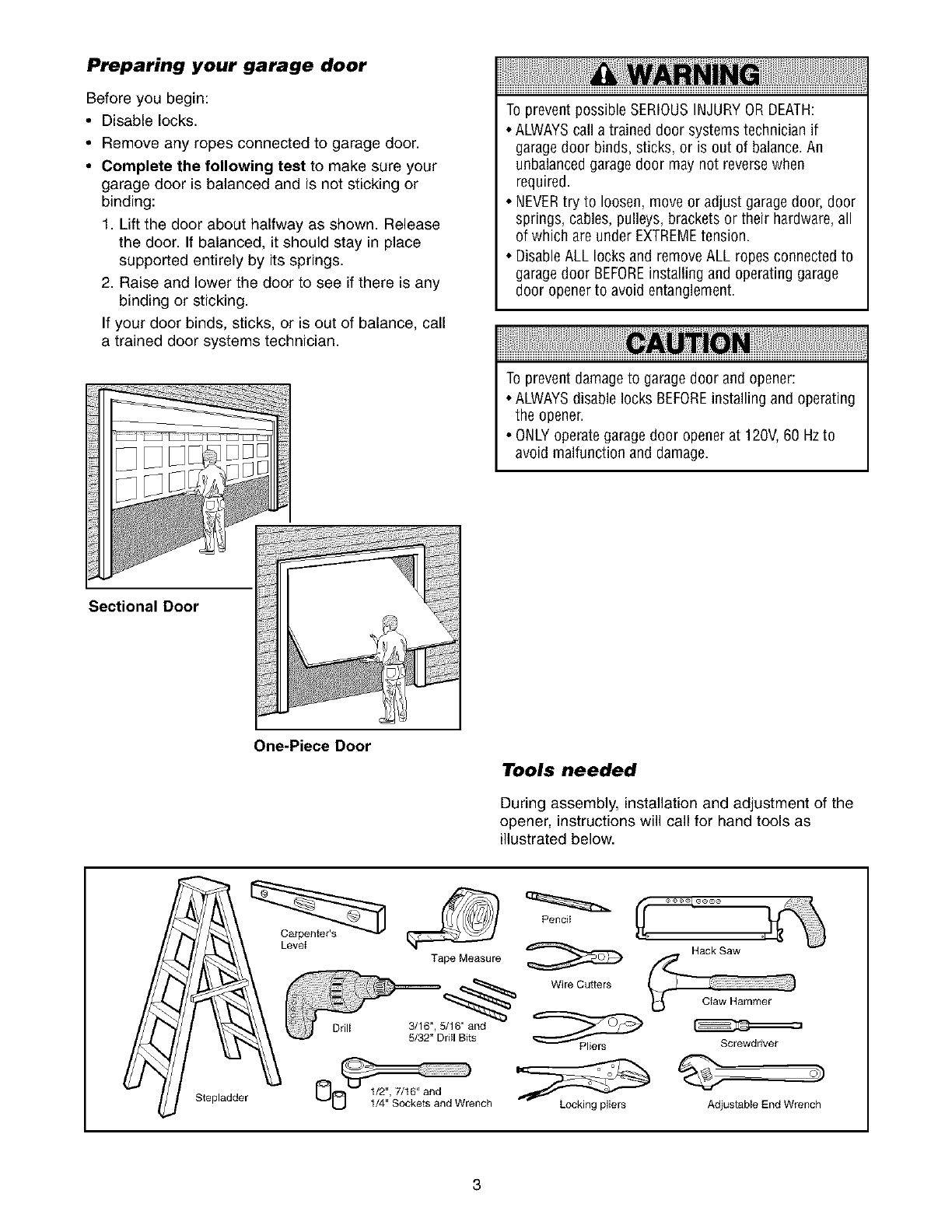
Preparing your garage door
Before you begin:
•Disable locks.
• Remove any ropes connected to garage door.
• Complete the following test to make sure your
garage door is balanced and is not sticking or
binding:
1. Lift the door about halfway as shown. Release
the door. If balanced, it should stay in place
supported entirely by its springs.
2. Raise and lower the door to see if there is any
binding or sticking.
If your door binds, sticks, or is out of balance, call
a trained door systems technician.
To prevent possible SERIOUSINJURYOR DEATH:
• ALWAYScall a trained door systems technician if
garagedoor binds, sticks, or is out of balance.An
unbalanced garagedoor may not reverse when
required.
• NEVERtry to loosen, move or adjust garagedoor, door
springs, cables, pulleys, brackets or their hardware,all
of which are under EXTREMEtension.
• DisableALL locks and remove ALL ropes connected to
garagedoor BEFOREinstalling and operating garage
door openerto avoid entanglement.
To prevent damage to garagedoor and opener:
• ALWAYSdisable locks BEFOREinstalling and operating
the opener.
• ONLYoperate garagedoor opener at 120V, 60 Hzto
avoid malfunction and damage.
Sectional Door
One-Piece Door
Levei
Tools needed
During assembly, installation and adjustment of the
opener, instructions will call for hand tools as
illustrated below.
Stepladder
Tape Measure
Drill 3/1B", 5/16" and
5/32" Dritl Bits
Pencit
Wire Cutters
Locking pliers
Hack Saw
Screwdriver
O)
AdjustabJe End Wrench
3
Planning
Identify the type and height of your garage door.
Survey your garage area to see if any of the
conditions below apply to your installation. Additional
materials may be required. You may find it helpful to
refer back to this page and the accompanying
illustrations as you proceed with the installation of
your opener.
Depending on your requirements, there are several
installation steps which may call for materials or
hardware not included in the carton.
•Installation Step 1 - Look at the wall or ceiling
above the garage door. The header bracket must
be securely fastened to structural supports.
• Installation Step 5 - Do you have a finished ceiling
in your garage? If so, a support bracket and
additional fastening hardware may be required.
• Installation Step 10 - Depending upon garage
construction, extension brackets or wood blocks
may be needed to install sensors.
• Installation Step 10 -Alternate floor mounting of
the safety reversing sensor will require hardware
not provided.
Do you have an access door in addition to the
garage door? If not, Model 53702 Emergency Key
Release is required. See Accessories page.
Look at the garage door where it meets the floor.
Any gap between the floor and the bottom of the
door must not exceed 1/4". Otherwise, the safety
reversal system may not work properly. See
Adjustment Step 3. Floor or door should be
repaired.
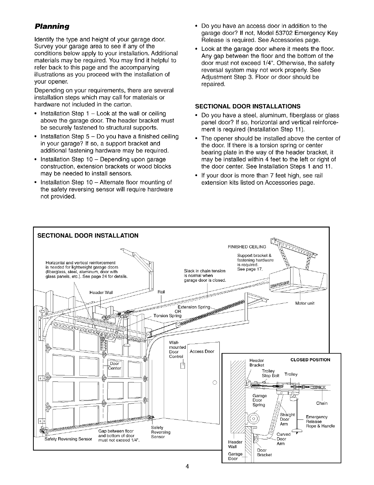
SECTIONAL DOOR INSTALLATIONS
• Do you have a steel, aluminum, fiberglass or glass
panel door? If so, horizontal and vertical reinforce-
ment is required (Installation Step 11).
The opener should be installed above the center of
the door. If there is a torsion spring or center
bearing plate in the way of the header bracket, it
may be installed within 4 feet to the left or right of
the door center. See Installation Steps 1 and 11.
• If your door is more than 7 feet high, see rail
extension kits listed on Accessories page.
SECTIONAL DOOR INSTALLATION
Horizontal and vertical reinforcement
is needed for lightweight garage doors
(fiberglass, sleel, aluminum, door with
glass panels, etc.). See page 24 for details.
Header Wall Rail
Slack in chain tension
is normal when
garage door is closed.
Extension Spring_
OR
Torsion Spring
FINISHED CEILING
Support bracket &
fastening hardware
is required.
See page 17.
Motor unit
Wa]b
Door
Control
afely Reversing Sensor
Gap between floor
and bottom of door
musl not exceed 1/4".
Safety
Reversing
Sensor
©
Header CLOSED POSITION
Bracket
Trolley
Slop Boit Troltey
Garage
Door
Spring Chain
Emergency
Release
Rope & Handle
Door
Arm
Door
Brackel
4
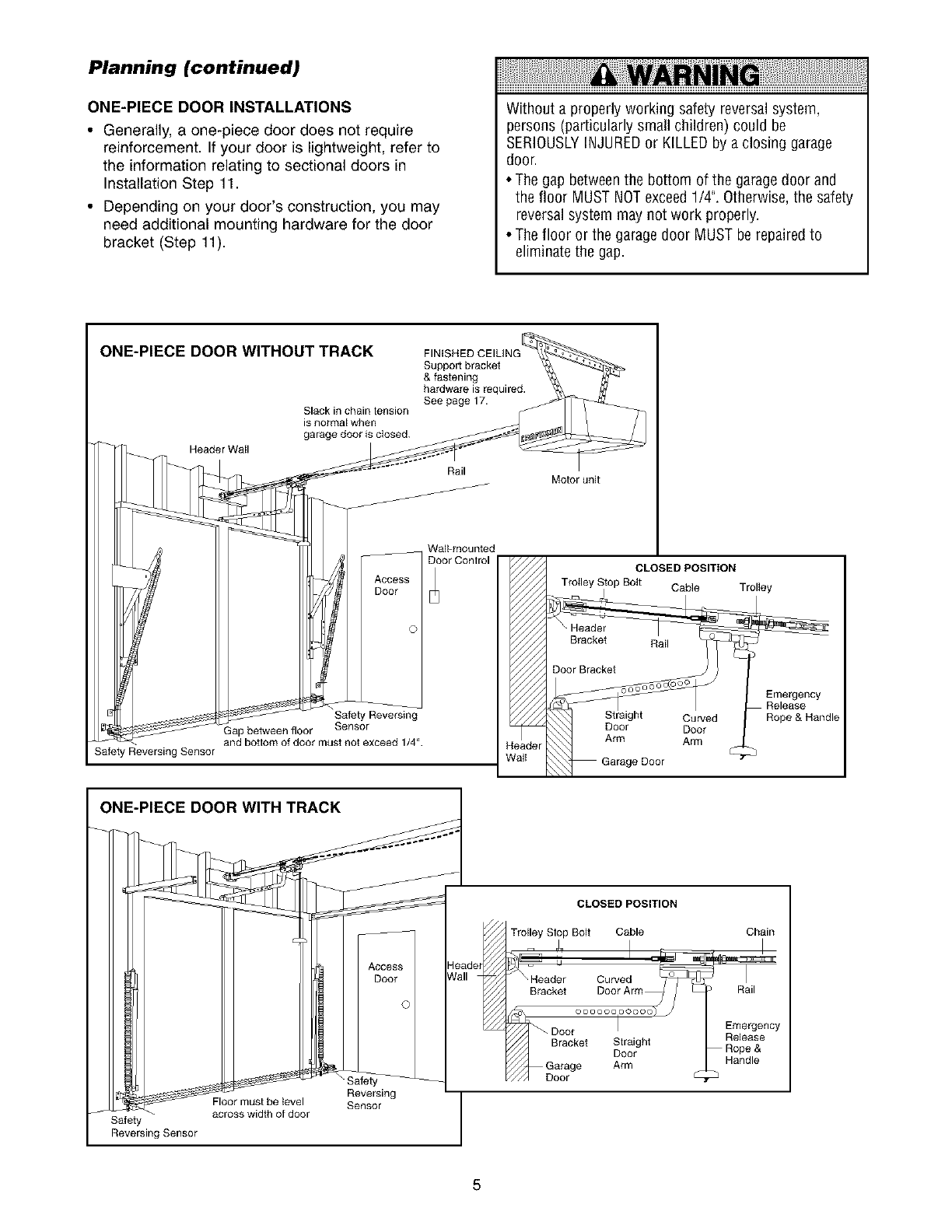
Planning (continued)
ONE-PIECE DOOR INSTALLATIONS
• Generally, a one-piece door does not require
reinforcement. If your door is lightweight, refer to
the information relating to sectional doors in
Installation Step 11.
• Depending on your door's construction, you may
need additional mounting hardware for the door
bracket (Step 11).
Without a properly working safety reversal system,
persons (particularly small children) could be
SERIOUSLYINJUREDor KILLEDby a closing garage
door.
• The gap betweenthe bottom of the garagedoor and
the floor MUST NOTexceed1/4". Otherwise,the safety
reversal system may not work properly.
• The floor or the garage door MUST be repaired to
eliminate the gap.
ONE-PIECE DOOR WITHOUT TRACK
Header Wall
Slack in chain tension
is norn_al when
garage door is closed.
FINI_
Suppo_ bracket
& fastening
hardware isrequired.
See page 17.
Rail Motor unit
I
Safety Reversing Sensor
WaIFmounted
D[_or Control
Access
Safety Reversing
Gap between floor Sensor
and bottom of door must not exceed 1/4".
ONE-PIECE DOOR WITH TRACK
CLOSED POSITION
Trolley Stop Bog Cable Trolley
D°°rBracle__ _
_ Emergency
Releaset Curved Rope & Handle
Door Door
leader Arm Arm
_aiI
Safety
Reversing Sensor
S
Floor must be {evel
across width of door
Access J
' ' Door I
, , ©1
Reversing
Sensor
F//,
CLOSED POSITION
Troiley Stop Bolt Cable
Bracket
LD °°°
Door
Bracket Slraight
Door
Garage Arm
oor •
Chain
Rail
Emergency
Release
Rope &
Handle
5
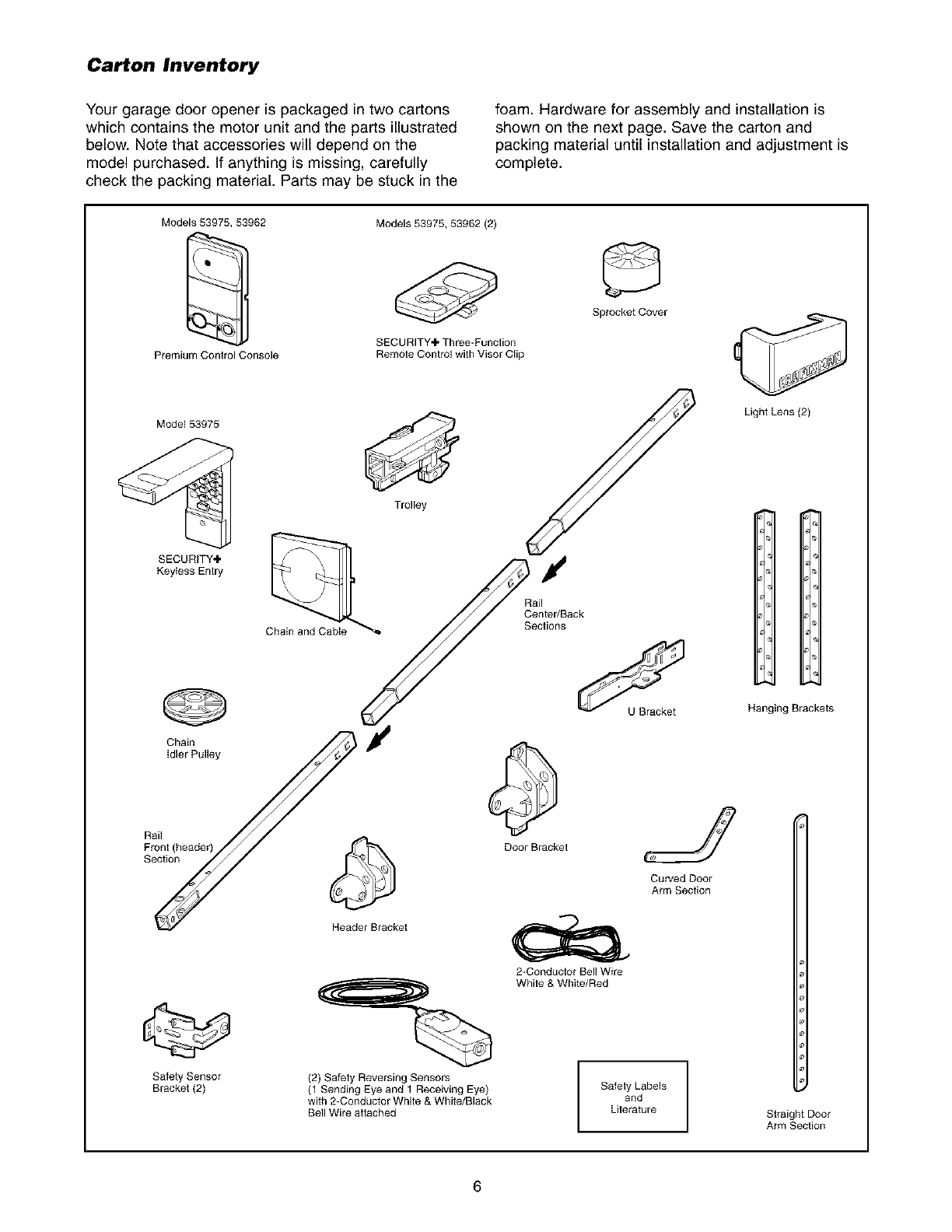
Carton Inventory
Your garage door opener is packaged in two cartons
which contains the motor unit and the parts illustrated
below. Note that accessories will depend on the
model purchased. If anything is missing, carefully
check the packing material. Parts may be stuck in the
foam. Hardware for assembly and installation is
shown on the next page. Save the carton and
packing material until installation and adjustment is
complete.
Models 53975, 53962
Premium Control Console
Model 53975
SECURITY÷
Keyiess Enlry
Models 53975, 53962 (2)
SECURITY÷ Three-Function
Remole Control wilh Visor Clip
@
Chain
idler Pulley
Trolley
f
Rail
Center/Back
Seclions
Sprocket Cover
Light Lens (2)
Hanging Brackets
Rail
Front (header)
Section
Safety Sensor
Bracket (2)
Header Bracket
(2) Safety Reversing Sensors
(1 Sending Eye and 1 Receiving Bye)
with 2-Conductor White & White/Black
Bell Wire atlached
Door Brackel
2-Conductor Bell Wire
White & White/Red
Curved Door
Arm Section
Safely Labels
and
Lilerature Straight Door
Arm Section
6
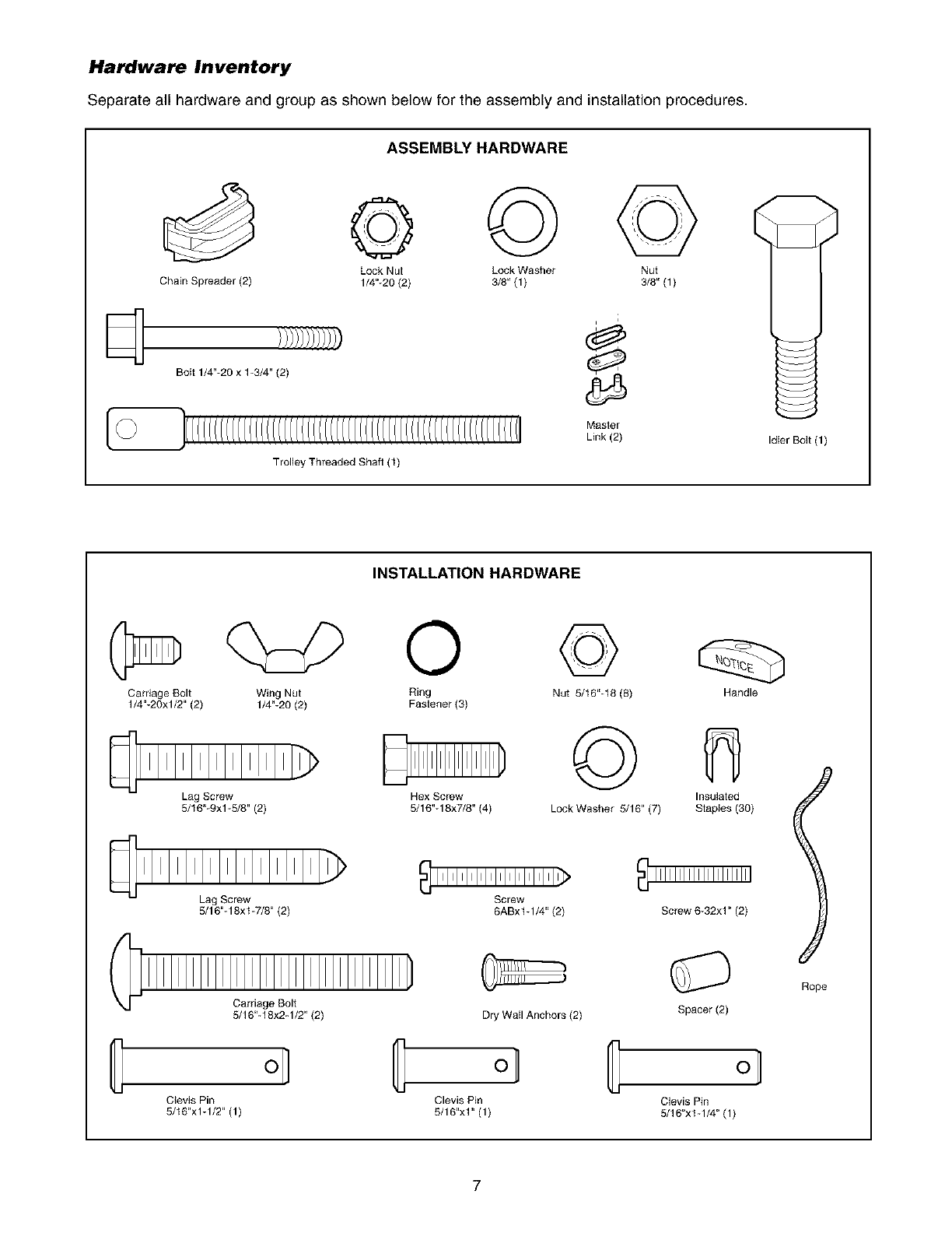
Hardware Inventory
Separate all hardware and group as shown below for the assembly and installation procedures.
ASSEMBLY HARDWARE
Lock Nut Lock Washer Nut
Chain Spreader (2) 1/4"-20 (2) 3/8" (1) 3/8" (1)
Bolt 1/4"-20 x 1-3/4" (2)
Trolley Threaded Shaft (1)
INSTALLATION HARDWARE
i
Master
Link (2) Idler Bolt (1)
Carriage Bolt
1/4"-20xl/2" (2)
O
Wing Nut Ring
1/4"-20 (2) Faslener (3)
Lag Screw Hex Screw
5/16"-9xl-5/8" (2) 5/16"-18x7/8" (4)
©
Nut 5/16"-18 (8)
©
Lock Washer 5/16" (7)
Handle
Insulaled
Staples (30)
Lag Screw Screw
5/16"-18xt -7/8" (2) 6ABxt -1/4" (2) Screw 6-32x1"(2)
G
Carriage Bolt
5/16"-18x2-1/2" (2) Dry Wall Anchors (2)
o] _ ol
C_evis Pin Clevis Pin
5/16"x1-1/2" (1) 5/16"x1" (1)
Spacer(2)
C ol
Clevis Pin
5/16"xt -1/4" (1)
Rope
7
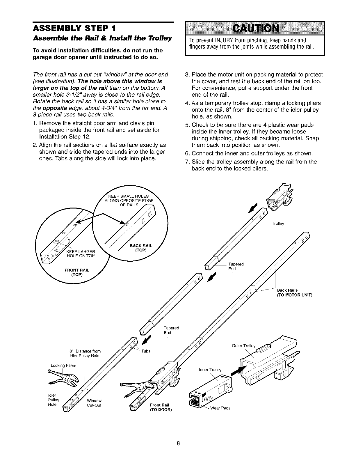
ASSEMBLY STEP 1
Assemble the Rail & Install the Trolley
To avoid installation difficulties, do not run the
garage door opener until instructed to do so.
To prevent INJURYfrom pinching, keep hands and
fingers awayfrom the joints while assembling the rail.
The front rail has a cut out "window" at the door end
(see illustration). The hole above this window is
larger on the top of the rail than on the bottom. A
smaller hole 3-1/2" away is close to the rail edge.
Rotate the back rail so it has a similar hole close to
the opposite edge, about 4-3/4" from the far end. A
3-piece rail uses two back rails.
1. Remove the straight door arm and clevis pin
packaged inside the front rail and set aside for
Installation Step 12.
2. Align the rail sections on a flat surface exactly as
shown and slide the tapered ends into the larger
ones. Tabs along the side will lock into place.
,
4,
5.
,
7.
Place the motor unit on packing material to protect
the cover, and rest the back end of the rail on top.
For convenience, put a support under the front
end of the rail.
As a temporary trolley stop, clamp a locking pliers
onto the rail, 8" from the center of the idler pulley
hole, as shown.
Check to be sure there are 4 plastic wear pads
inside the inner trolley. If they became loose
during shipping, check all packing material. Snap
them back into position as shown.
Connect the inner and outer trolleys as shown.
Slide the trolley assembly along the rail from the
back end to the locked pliers.
Back Rails
(TO MOTOR UNIT)
8I' Distance from
idler Pulley Hole
Locking Pliers
Idler
Window
Hole Cut-Out
End
Front Rail
(TO DOOR)
__Outer Trotley
Wear Pads
8
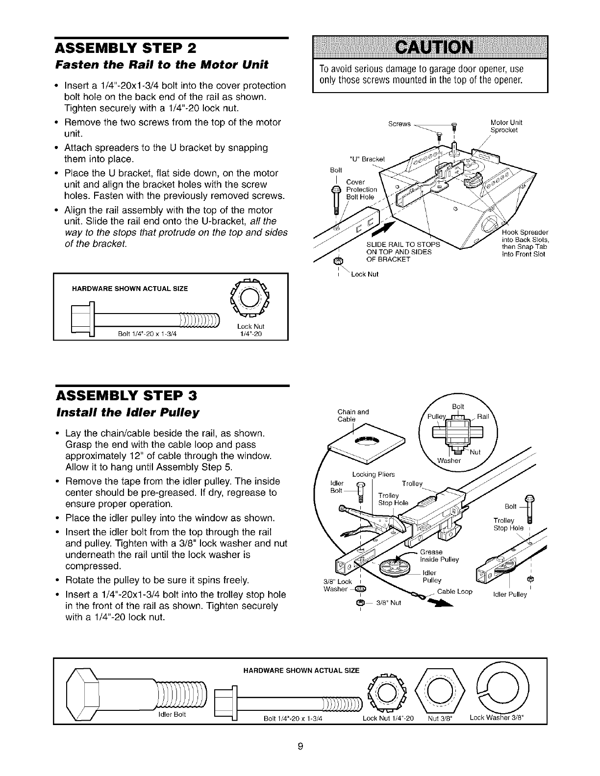
ASSEMBLY STEP 2
Fasten the Rail to the Motor Unit
•Insert a 1/4"-20xl-3/4 bolt into the cover protection
bolt hole on the back end of the rail as shown.
Tighten securely with a 1/4"-20 lock nut.
• Remove the two screws from the top of the motor
unit.
• Attach spreaders to the U bracket by snapping
them into place.
• Place the U bracket, flat side down, on the motor
unit and align the bracket holes with the screw
holes. Fasten with the previously removed screws.
• Align the rail assembly with the top of the motor
unit. Slide the rail end onto the U-bracket, all the
way to the stops that protrude on the top and sides
of the bracket.
HARDWARE SHOWN ACTUAL SIZE _'_P'_'_'_"t
Lock Nut
Boit 1/4"-20 x 1-3/4 1/4"-20
To avoid serious damageto garage door opener, use
only those screws mounted in the top of the opener.
Boll
Screws Motor Unit
Sprocket
/
"U" Bracket
Cover
ON TOP AND SIDES
OF BRACKET
"Lock Nut
dook Spreader
into Back Slots,
then Snap Tab
into Front SIot
ASSEMBLY STEP 3
Install the Idler Pulley
• Lay the chain/cable beside the rail, as shown.
Grasp the end with the cable loop and pass
approximately 12" of cable through the window.
Allow it to hang until Assembly Step 5.
• Remove the tape from the idler pulley. The inside
center should be pre-greased. If dry, regrease to
ensure proper operation.
• Place the idler pulley into the window as shown.
• Insert the idler bolt from the top through the rail
and pulley. Tighten with a 3/8" lock washer and nut
underneath the rail until the lock washer is
compressed.
• Rotate the pulley to be sure it spins freely.
• Insert a 1/4"-20xl-3/4 bolt into the trolley stop hole
in the front of the rail as shown. Tighten securely
with a 1/4"-20 lock nut.
Chain and
Cable
Locking Pliers
Idler
Bott Trolley
Stop Hole
\
3/8"Lock I
Washer_
_1 3/8" Nut
I
Boll
Trolley
Stop Hole
insidePulleyPulley _:
_ Cable Loop idler Pulley
HARDWARE SHOWN ACTUAL SIZE ©
Idler Boit Bolt 1/4"-20 x 1-3/4))))))')')'))'))Lock Nut 1/4"-20 Nut3/8" Lock Washer3/8"
9
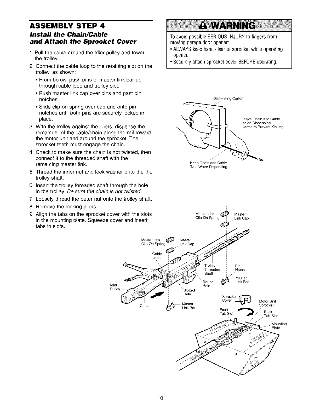
ASSEMBLY STEP 4
Install the Chain/Cable
and Attach the Sprocket Cover
1. Pull the cable around the idler pulley and toward
the trolley.
2. Connect the cable loop to the retaining slot on the
trolley, as shown:
• From below, push pins of master link bar up
through cable loop and trolley slot.
• Push master link cap over pins and past pin
notches.
• Slide clip-on spring over cap and onto pin
notches until both pins are securely locked in
place.
3. With the trolley against the pliers, dispense the
remainder of the cable/chain along the rail toward
the motor unit and around the sprocket. The
sprocket teeth must engage the chain.
4. Check to make sure the chain is not twisted, then
connect it to the threaded shaft with the
remaining master link.
5. Thread the inner nut and lock washer onto the the
trolley shaft.
6. Insert the trolley threaded shaft through the hole
in the trolley. Be sure the chain is not twisted.
7. Loosely thread the outer nut onto the trolley shaft.
8. Remove the locking pliers.
9. Align the tabs on the sprocket cover with the slots
in the mounting plate. Squeeze cover and insert
tabs in slots.
To avoid possible SERIOUSINJURYto fingers from
moving garage door opener:
• ALWAYSkeep hand clear of sprocket while operating
opener.
• Securelyattach sprocket cover BEFOREoperating.
Dispensing Carton
Leave Chain and Cable
Inside Dispensing
Carton to Prevent Kinking.
Keep Chain and Cable
Taut When Dispensing
Master Link._ Master
Chp-On Spnng _ Ltnk Cap
I i
Master Link _ Master
Clip-OnSpringCable_ _r'-___jl1 Link Cap ' i
Trolley : , Pin
edThreaded , I Noch
Shaft i :
i Master r
Round Link Bar
Idler
Pulley I ' Slotted
, i Hole
: : Cover
Cable ........ _"
(_ Unk Bar Front ' '
Tab SIot :
Motor Unit
Sprocket
Back
Tab Slot
Mounting
10
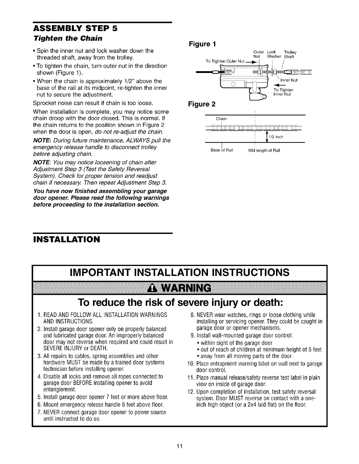
ASSEMBLY STEP 5
Tighten the Chain
• Spin the inner nut and lock washer down the
threaded shaft, away from the trolley.
• To tighten the chain, turn outer nut in the direction
shown (Figure 1).
• When the chain is approximately 1/2" above the
base of the rail at its midpoint, re-tighten the inner
nut to secure the adjustment.
Sprocket noise can result if chain is too loose.
When installation is complete, you may notice some
chain droop with the door closed. This is normal. If
the chain returns to the position shown in Figure 2
when the door is open, do not re-adjust the chain.
NOTE: During future maintenance, ALWAYS pull the
emergency release handle to disconnect trolley
before adjusting chain.
NOTE: You may notice loosening of chain after
Adjustment Step 3 (Test the Safety Reversal
System). Check for proper tension and readjust
chain if necessary. Then repeat Adjustment Step 3.
You have now finished assembling your garage
door opener. Please read the following warnings
before proceeding to the installation section.
Figure 1
Outer Lock Trolley
Nut Washer Shaft
Figure 2
Chain i
Base of Rail Mid length of Rail
INSTALLATION
IMPORTANT INSTALLATION INSTRUCTIONS
To reduce the risk of severe injury or death:
1. READAND FOLLOWALL INSTALLATIONWARNINGS
AND INSTRUCTIONS.
2. Install garage door opener only on properly balanced
and lubricated garagedoor. An improperly balanced
door may not reversewhen required and could result in
SEVEREINJURYor DEATH.
3. All repairs to cables, spring assembliesand other
hardware MUST be made by a trained door systems
technician before installing opener.
4. Disableall locks and remove all ropes connected to
garagedoor BEFOREinstalling openerto avoid
entanglement.
5. Install garage door opener 7 feet or more above floor.
6. Mount emergency releasehandle 6 feet above floor.
7. NEVERconnect garage door openerto power source
until instructed to do so.
8. NEVERwear watches, rings or loose clothing while
installing or servicing opener.They could be caught in
garagedoor or opener mechanisms.
9. Install wall-mounted garagedoor control:
• within sight of the garage door
• out of reachof children at minimum height of 5 feet
• awayfrom all moving parts of the door.
10. Placeentrapment warning label on wall next to garage
door control.
11. Placemanual release/safetyreversetest label in plain
view on inside of garagedoor.
12. Upon completion of installation, test safety reversal
system. Door MUST reverse on contact with a one-
inch high object (or a 2x4 laid flat) on the floor.
11
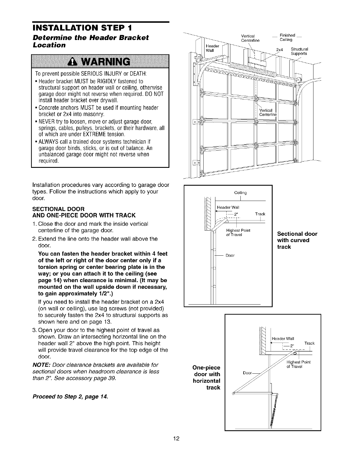
INSTALLATION STEP 1
Determine the Header Bracket
Location
To prevent possible SERIOUSINJURYor DEATH:
•Header bracket MUST be RIGIDLYfastened to
structural support on headerwall or ceiling, otherwise
garagedoor might not reversewhen required. DO NOT
install header bracket over drywall.
• Concrete anchors MUST be used if mounting header
bracket or 2x4 into masonry.
• NEVERtry to loosen, move or adjust garagedoor,
springs, cables, pulleys, brackets, or their hardware, all
of which are under EXTREMEtension.
• ALWAYScall a trained door systems technician if
garagedoor binds, sticks, or is out of balance.An
unbalanced garagedoor might not reversewhen
required.
Vertical Finished
Centerline Ceiling
2_ Slructural
Suppo_s
Installation procedures vary according to garage door
types• Follow the instructions which apply to your
door.
SECTIONAL DOOR
AND ONE-PIECE DOOR WITH TRACK
1. Close the door and mark the inside vertical
centerline of the garage door.
2. Extend the line onto the header wall above the
door.
You can fasten the header bracket within 4 feet
of the left or right of the door center only if a
torsion spring or center bearing plate is in the
way; or you can attach it to the ceiling (see
page 14) when clearance is minimal. (It may be
mounted on the wall upside down if necessary,
to gain approximately 1/2".)
If you need to install the header bracket on a 2x4
(on wall or ceiling), use lag screws (not provided)
to securely fasten the 2x4 to structural supports as
shown here and on page 13.
3. Open your door to the highest point of travel as
shown• Draw an intersecting horizontal line on the
header wall 2" above the high point• This height
will provide travel clearance for the top edge of the
door.
NOTE: Door clearance brackets are available for
sectional doors when headroom clearance is less
than 2"• See accessory page 39.
Proceed to Step 2, page 14.
Ceiling
Header Wall
Highest Point
of Travel
Door
Track
I
Sectional door
with curved
track
One-piece
door with
horizontal
track
Header Wall
:2" Track
Highest Point
of Travel
12
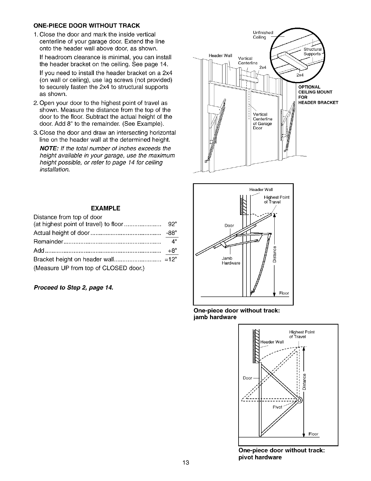
ONE-PIECE DOOR WITHOUT TRACK
1. Close the door and mark the inside vertical
centerline of your garage door. Extend the line
onto the header wall above door, as shown.
If headroom clearance is minimal, you can install
the header bracket on the ceiling. See page 14.
If you need to install the header bracket on a 2x4
(on wall or ceiling), use lag screws (not provided)
to securely fasten the 2x4 to structural supports
as shown.
2. Open your door to the highest point of travel as
shown. Measure the distance from the top of the
door to the floor. Subtract the actual height of the
door. Add 8" to the remainder. (See Example).
3. Close the door and draw an intersecting horizontal
line on the header wall at the determined height.
NOTE: ff the total number of inches exceeds the
height available in your garage, use the maximum
height possible, or refer to page 14 for ceiling
installation.
Header Wall
Unfinished
Ceiling
Vertical
Centedine 2x4
CEILING MOUNT
FOR
HEADER BRACKET
EXAMPLE
Distance from top of door
(at highest point of travel) to floor ...................... 92"
Actual height of door .......................................... -88"
Remainder .......................................................... 4"
Add ..................................................................... +8"
Bracket height on header wall ............................. 12"
(Measure UP from top of CLOSED door.)
Proceed to Step 2, page 14.
Door
JHaa_dbware
Header Wall
_ _ighest Point
of Travel
?TFloor
One-piece door without track:
jamb hardware
Highest Poinl
of Travel
H_der Wall /
i
Ii
Ii
Ii
Ii
Door '' c°
r_
a
Floor
One-piece door without track:
pivot hardware
13
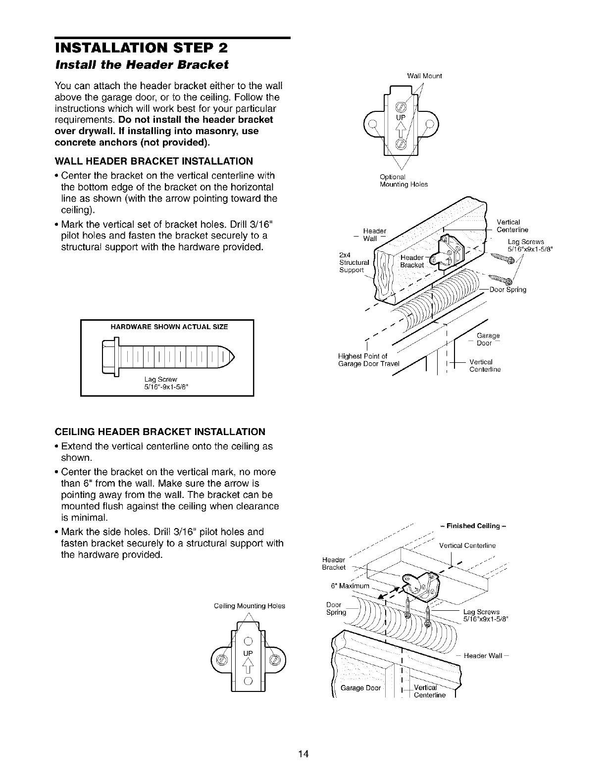
INSTALLATION STEP 2
Install the Header Bracket
You can attach the header bracket either to the wall
above the garage door, or to the ceiling. Follow the
instructions which will work best for your particular
requirements. Do not install the header bracket
over drywall. If installing into masonry, use
concrete anchors (not provided).
WALL HEADER BRACKET INSTALLATION
•Center the bracket on the vertical centerline with
the bottom edge of the bracket on the horizontal
line as shown (with the arrow pointing toward the
ceiling).
• Mark the vertical set of bracket holes. Drill 3/16"
pilot holes and fasten the bracket securely to a
structural support with the hardware provided.
HARDWARE SHOWN ACTUAL SIZE
Lag Screw
5/16"-9xl-5/8"
Walt Mount
Optional
Mounting Holes
Header
Wall
2x4
Structural
Suppo_
/
/
/
" j
Highest Point of
Garage Door Travel
Ve_ical
Centertine
Lag Screws
5/16"x9xl-5/8"
Door Spring
Garage
Door
Centerline
CEILING HEADER BRACKET INSTALLATION
• Extend the vertical centerline onto the ceiling as
shown.
• Center the bracket on the vertical mark, no more
than 6" from the wall. Make sure the arrow is
pointing away from the wall. The bracket can be
mounted flush against the ceiling when clearance
is minimal.
• Mark the side holes. Drill 3/16" pilot holes and
fasten bracket securely to a structural support with
the hardware provided.
Ceiling Mounting Holes
Header /
Bracket
Door J
Lag Screws
5/16"x9xt -5/8"
Header Wall
Centerfine
14
Header Wall
j Header Bracket
J
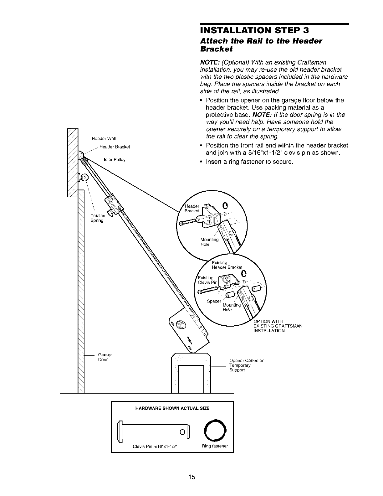
INSTALLATION STEP 3
Attach the Rail to the Header
Bracket
NOTE: (Optional) With an existing Craftsman
installation, you may re-use the old header bracket
with the two plastic spacers included in the hardware
bag. Place the spacers inside the bracket on each
side of the rail, as illustrated.
•Position the opener on the garage floor below the
header bracket. Use packing material as a
protective base. NOTE: If the door spring is in the
way you'll need help. Have someone hold the
opener securely on a temporary support to allow
the rail to clear the spring.
• Position the front rail end within the header bracket
and join with a 5/16"x1-1/2" clevis pin as shown.
• Insert a ring fastener to secure.
Spring
/
Mounting
Hole
Header Bracket0
Mountinc
Hole
IPTION WITH
EXISTING CRAFTSMAN
INSTALLATION
Garage
Door Opener Carton or
Temporary
Support
HARDWARE SHOWN ACTUAL SIZE
O
Clevis Pin 5/16"x1-1/2" Ring faslener
15
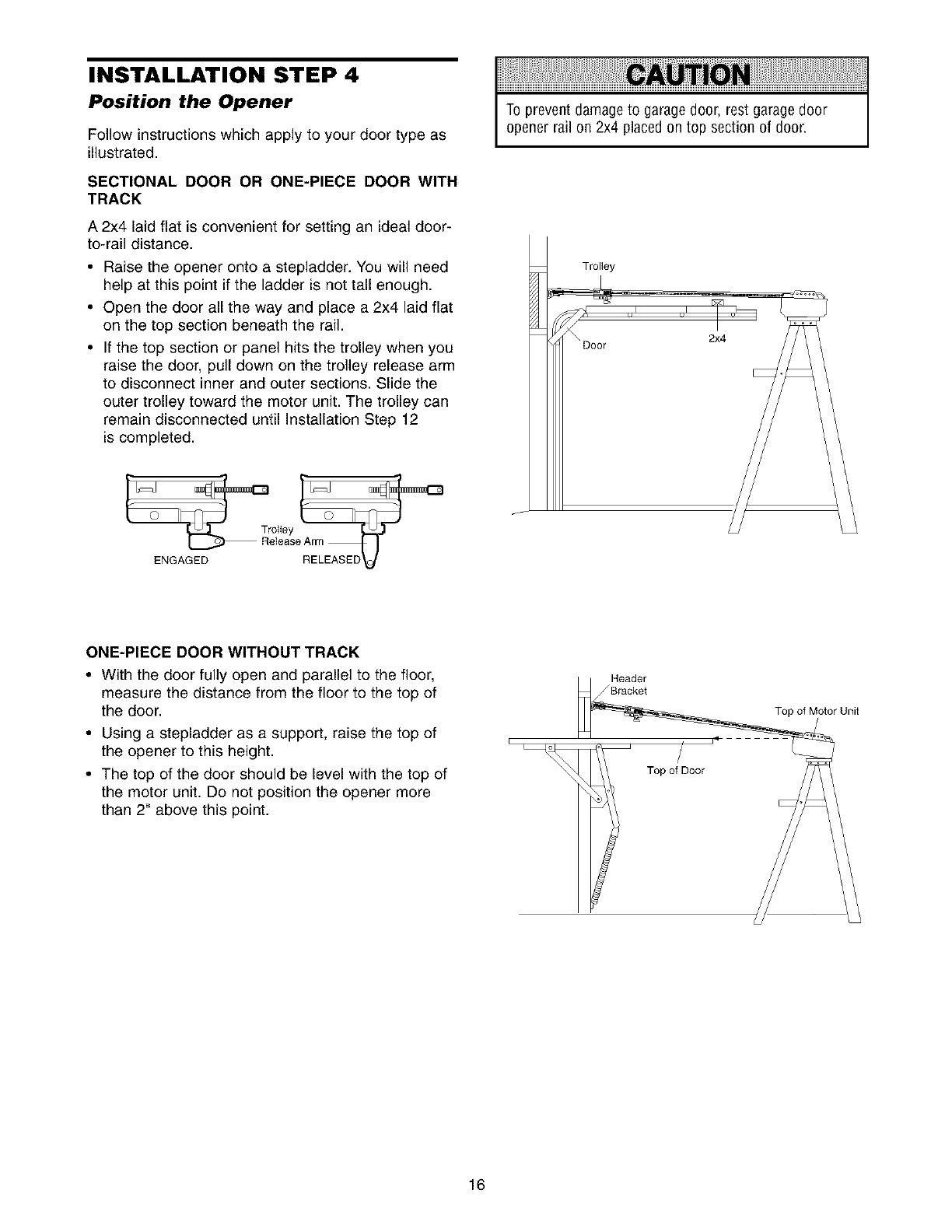
INSTALLATION STEP 4
Position the Opener
Follow instructions which apply to your door type as
illustrated.
SECTIONAL DOOR OR ONE-PIECE DOOR WITH
TRACK
A 2x4 laid flat is convenient for setting an ideal door-
to-rail distance.
•Raise the opener onto a stepladder. You will need
help at this point if the ladder is not tall enough.
• Open the door all the way and place a 2x4 laid flat
on the top section beneath the rail.
• If the top section or panel hits the trolley when you
raise the door, pull down on the trolley release arm
to disconnect inner and outer sections. Slide the
outer trolley toward the motor unit. The trolley can
remain disconnected until Installation Step 12
is completed.
To prevent damage to garagedoor, rest garage door
opener rail on 2x4 placed on top section of door.
2x4
ENGAGED
ONE-PIECE DOOR WITHOUT TRACK
• With the door fully open and parallel to the floor,
measure the distance from the floor to the top of
the door.
• Using a stepladder as a support, raise the top of
the opener to this height.
• The top of the door should be level with the top of
the motor unit. Do not position the opener more
than 2" above this point.
i
16
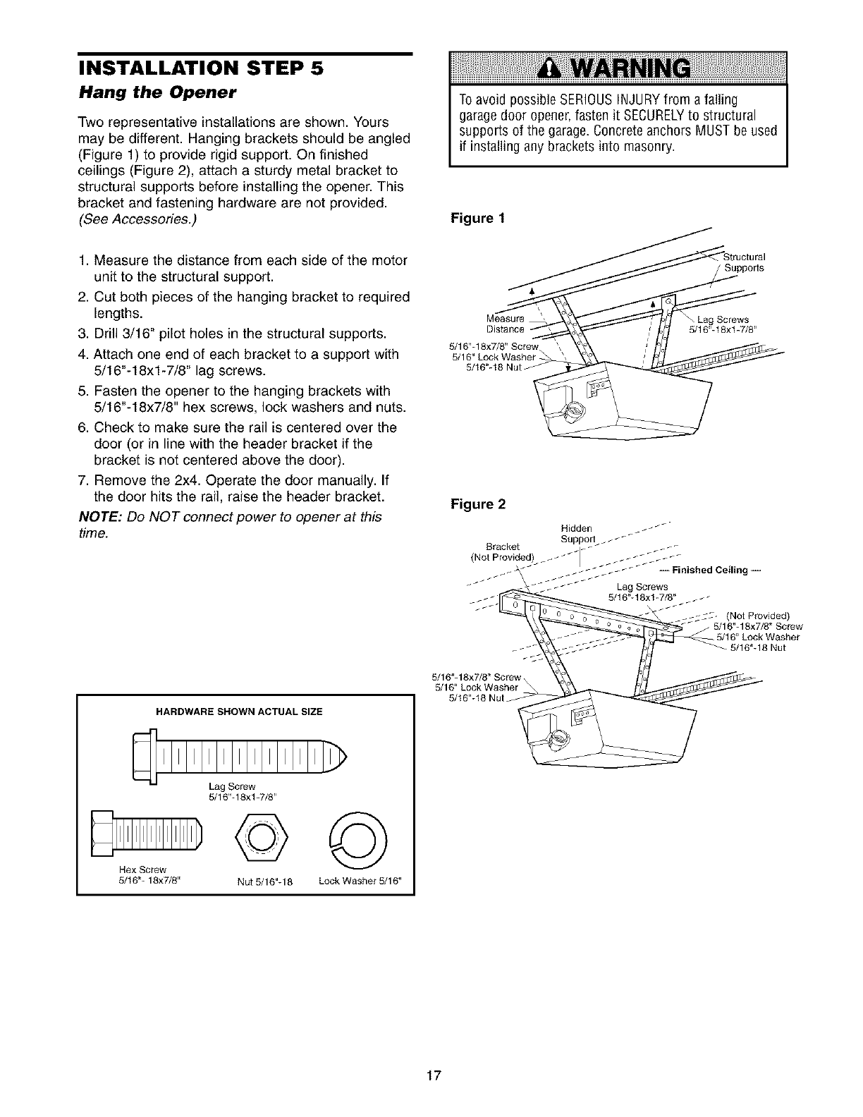
INSTALLATION STEP 5
Hang the Opener
Two representative installations are shown. Yours
may be different. Hanging brackets should be angled
(Figure 1) to provide rigid support. On finished
ceilings (Figure 2), attach a sturdy metal bracket to
structural supports before installing the opener. This
bracket and fastening hardware are not provided.
(See Accessories.)
To avoid possible SERIOUSINJURYfrom afalling
garagedoor opener,fasten it SECURELYto structural
supports of the garage. Concrete anchors MUST be used
if installing any brackets into masonry.
Figure 1
1. Measure the distance from each side of the motor
unit to the structural support.
2. Cut both pieces of the hanging bracket to required
lengths.
3. Drill 3/16" pilot holes in the structural supports.
4. Attach one end of each bracket to a support with
5/16"-18xl-7/8" lag screws.
5. Fasten the opener to the hanging brackets with
5/16"-18x7/8" hex screws, lock washers and nuts.
6. Check to make sure the rail is centered over the
door (or in line with the header bracket if the
bracket is not centered above the door).
7. Remove the 2x4. Operate the door manually. If
the door hits the rail, raise the header bracket.
NOTE: Do NOT connect power to opener at this
time.
HARDWARE SHOWN ACTUAL SIZE
Hex Screw
5/16"- 18x7/8"
Lag Screw
5/16"-18xl-7/8"
©
Nut 5/16"-18
©
Lock Washer 5/16"
Supports
Measure
Distance 5/16"-18xt-7/8"
Figure 2
-5/16"-18 Nut
5/16"- 18x7/8" Screw %
5/16" Lock Washer
5/16"-18 Nut_
17
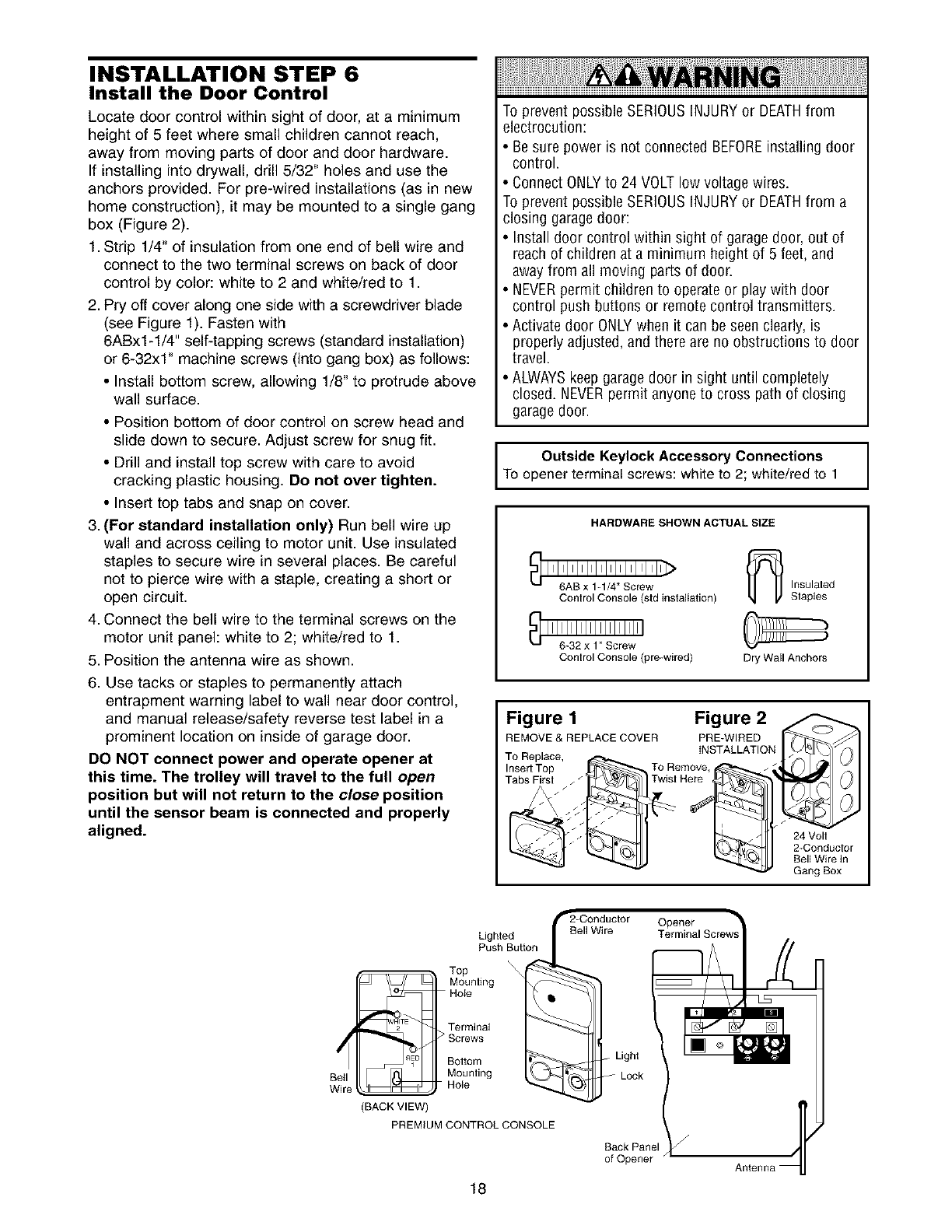
INSTALLATION STEP 6
Install the Door Control
Locate door control within sight of door, at a minimum
height of 5 feet where small children cannot reach,
away from moving parts of door and door hardware.
If installing into drywall, drill 5/32" holes and use the
anchors provided. For pre-wired installations (as in new
home construction), it may be mounted to a single gang
box (Figure 2).
1. Strip 1/4" of insulation from one end of bell wire and
connect to the two terminal screws on back of door
control by color: white to 2 and white/red to 1.
2. Pry off cover along one side with a screwdriver blade
(see Figure 1). Fasten with
6ABx1-1/4" self-tapping screws (standard installation)
or 6-32xl" machine screws (into gang box) as follows:
•Install bottom screw, allowing 1/8" to protrude above
wall surface.
• Position bottom of door control on screw head and
slide down to secure. Adjust screw for snug fit.
• Drill and install top screw with care to avoid
cracking plastic housing. Do not over tighten.
• Insert top tabs and snap on cover.
3. (For standard installation only) Run bell wire up
wall and across ceiling to motor unit. Use insulated
staples to secure wire in several places. Be careful
not to pierce wire with a staple, creating a short or
open circuit.
4. Connect the bell wire to the terminal screws on the
motor unit panel: white to 2; white/red to 1.
5. Position the antenna wire as shown.
6. Use tacks or staples to permanently attach
entrapment warning label to wall near door control,
and manual release/safety reverse test label in a
prominent location on inside of garage door.
DO NOT connect power and operate opener at
this time. The trolley will travel to the full open
position but will not return to the close position
until the sensor beam is connected and properly
aligned.
To prevent possible SERIOUSINJURYor DEATHfrom
electrocution:
• Be sure power is not connected BEFOREinstalling door
control.
• Connect ONLYto 24 VOLT low voltage wires.
To prevent possible SERIOUSINJURYor DEATHfrom a
closing garagedoor:
• Install door control within sight of garage door, out of
reach of children at a minimum height of 5 feet, and
awayfrom all moving parts of door.
• NEVERpermit children to operate or play with door
control push buttons or remote control transmitters.
• Activate door ONLYwhen it can be seen clearly, is
properly adjusted, and there are no obstructions to door
travel.
• ALWAYSkeep garagedoor insight until completely
closed. NEVERpermit anyoneto cross path of closing
garagedoor.
Outside Keylock Accessory Connections
To opener terminal screws: white to 2; white/red to 1
HARDWARE SHOWN ACTUAL SIZE
Control Console (std instaliation) Insulated
Staples
Control Console (pre-wired) Dry Wail Anchors
Figure 1 Figure 2
REMOVE & REPLACE COVER PRE-WIRED
INSTALLATION
TO Replace, _
Insert Top To Remove
Tabs Firsl / / z Twist Here
?24 Volt
2-Conductor
Bell Wire in
Gang Box
Wire
Lighted
Push Button
Top
Mounting
Hole
Terminal
"""""_ > Screws
Bottom
Mounting
Hole
BACK VIEW
PREMIUM CONTROL CONSOLE
Back Panel
of Opener
18
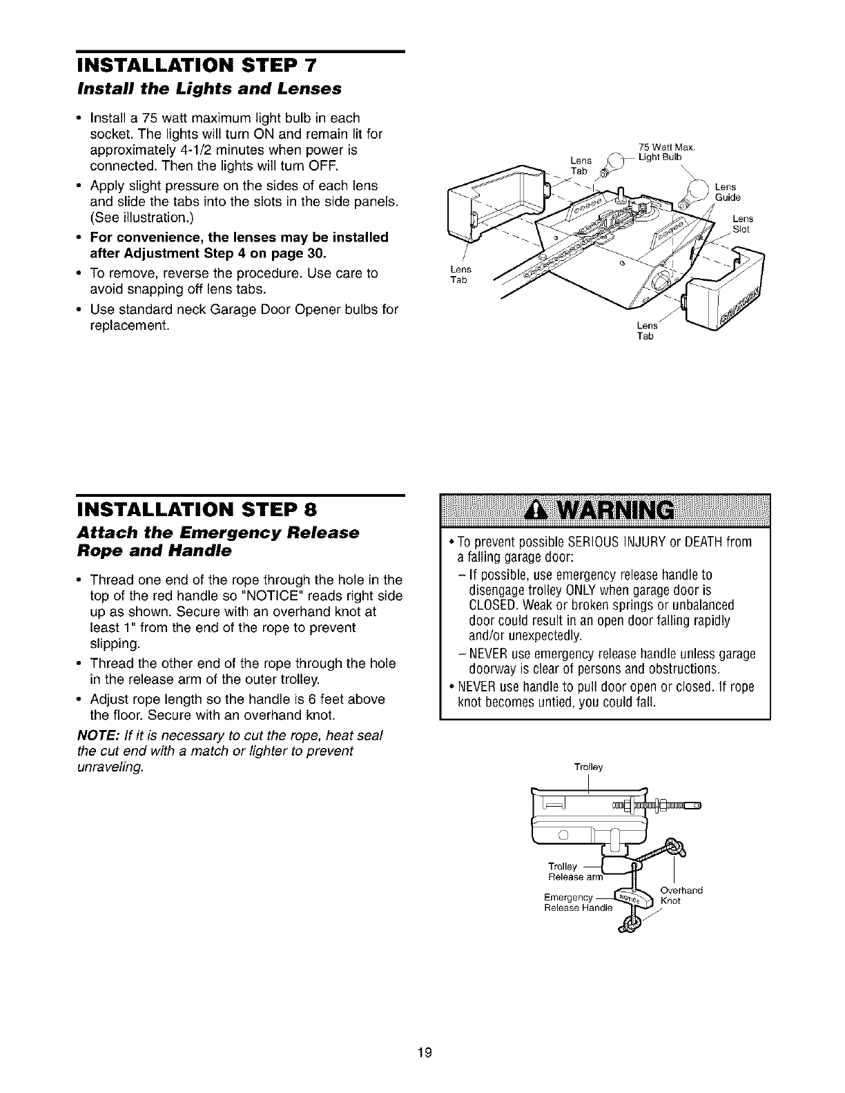
INSTALLATION STEP 7
Install the Lights and Lenses
•Install a 75 watt maximum light bulb in each
socket. The lights will turn ON and remain lit for
approximately 4-1/2 minutes when power is
connected. Then the lights will turn OFF.
• Apply slight pressure on the sides of each lens
and slide the tabs into the slots in the side panels.
(See illustration.)
• For convenience, the lenses may be installed
after Adjustment Step 4 on page 30.
• To remove, reverse the procedure. Use care to
avoid snapping off lens tabs.
• Use standard neck Garage Door Opener bulbs for
replacement.
/
Lens
Tab
75 Watl Max.
LenSrab/_ Lighl Bulb
Lensf
Tab
Lens
Guide
Lens
Siot
/
INSTALLATION STEP 8
Attach the Emergency Release
Rope and Handle
• Thread one end of the rope through the hole in the
top of the red handle so "NOTICE" reads right side
up as shown. Secure with an overhand knot at
least 1" from the end of the rope to prevent
slipping.
• Thread the other end of the rope through the hole
in the release arm of the outer trolley.
• Adjust rope length so the handle is 6 feet above
the floor. Secure with an overhand knot.
NOTE: If it is necessary to cut the rope, heat seal
the cut end with a match or lighter to prevent
unraveling.
• To prevent possible SERIOUSINJURYor DEATHfrom
a falling garagedoor:
-If possible, use emergency releasehandleto
disengage trolley ONLYwhen garagedoor is
OLOSED.Weakor broken springs or unbalanced
door could result in an open door falling rapidly
and/or unexpectedly.
-NEVERuse emergency releasehandle unless garage
doorway is clear of persons and obstructions.
• NEVERusehandle to pull door open or closed. If rope
knot becomes untied, you could fall.
Trolley
Emergency _, _) KCVe[hand
Release Handle i_
19
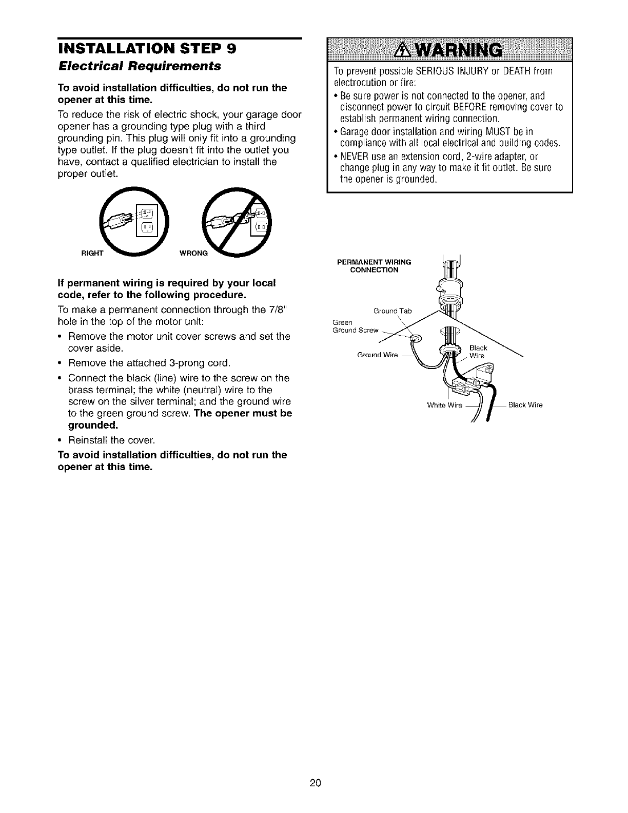
INSTALLATION STEP 9
Electrical Requirements
To avoid installation difficulties, do not run the
opener at this time.
To reduce the risk of electric shock, your garage door
opener has a grounding type plug with a third
grounding pin. This plug will only fit into a grounding
type outlet. If the plug doesn't fit into the outlet you
have, contact a qualified electrician to install the
proper outlet.
If permanent wiring is required by your local
code, refer to the following procedure.
To make a permanent connection through the 7/8"
hole in the top of the motor unit:
• Remove the motor unit cover screws and set the
cover aside.
• Remove the attached 3-prong cord.
• Connect the black (line) wire to the screw on the
brass terminal; the white (neutral) wire to the
screw on the silver terminal; and the ground wire
to the green ground screw. The opener must be
grounded.
• Reinstall the cover.
To avoid installation difficulties, do not run the
opener at this time.
To prevent possibleSERIOUSINJURYor DEATHfrom
electrocution or fire:
• Be sure poweris not connected to the opener, and
disconnect power to circuit BEFOREremoving cover to
establish permanent wiring connection.
• Garagedoor installation and wiring MUST be in
compliance with all local electrical and building codes.
• NEVERuse an extension cord, 2-wire adapter,or
change plugin any way to makeit fit outlet. Be sure
the opener is grounded.
PERMANENT WIRING
CONNECTION
Ground Tab
\
Green \\
Ground Screw
Black
Wire
20
INSTALLATION STEP 10
Install The Safety Reversing Sensor
The safety reversing sensor must be connected
and aligned correctly before the garage door
opener will move in the down direction.
IMPORTANT INFORMATION ABOUT
THE SAFETY REVERSING SENSOR
When properly connected and aligned, the sensor
will detect an obstacle in the path of its electronic
beam. The sending eye (with an orange indicator
light) transmits an invisible light beam to the
receiving eye (with a green indicator light). If an
obstruction breaks the light beam while the door is
closing, the door will stop and reverse to full open
position, and the opener lights will flash 10 times.
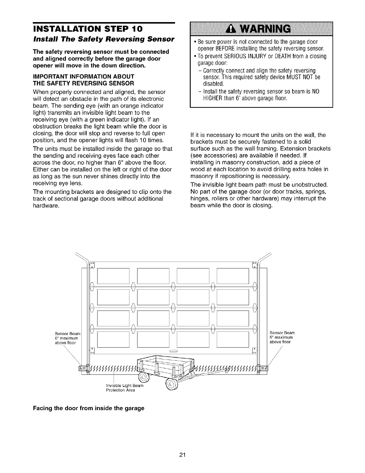
The units must be installed inside the garage so that
the sending and receiving eyes face each other
across the door, no higher than 6" above the floor.
Either can be installed on the left or right of the door
as long as the sun never shines directly into the
receiving eye lens.
The mounting brackets are designed to clip onto the
track of sectional garage doors without additional
hardware.
•Be sure power is not connected to the garage door
opener BEFOREinstalling the safety reversing sensor.
• To prevent SERIOUSINJURYor DEATHfrom a closing
garagedoor:
-Correctly connect and align the safety reversing
sensor. This required safety device MUST NOTbe
disabled.
-Install the safety reversing sensor so beam is NO
HIGHERthan 6" above garagefloor.
If it is necessary to mount the units on the wall, the
brackets must be securely fastened to a solid
surface such as the wall framing. Extension brackets
(see accessories) are available if needed. If
installing in masonry construction, add a piece of
wood at each location to avoid drilling extra holes in
masonry if repositioning is necessary.
The invisible light beam path must be unobstructed.
No part of the garage door (or door tracks, springs,
hinges, rollers or other hardware) may interrupt the
beam while the door is closing.
Sensor Beam
B" maximum
above floor
\
SensorBeam
6" maximum
above floor
invisible Light Beam
Protection Area
Facing the door from inside the garage
21
INSTALLING THE BRACKETS
Be sure power to the opener is disconnected.
Install and align the brackets so the sensors will face
each other across the garage door, with the beam no
higher than 6" above the floor. They may be installed
in one of three ways, as follows.
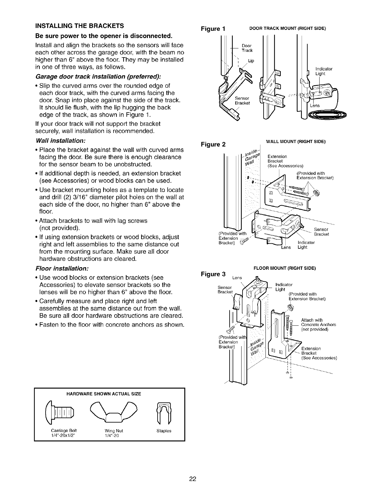
Garage door track installation (preferred):
•Slip the curved arms over the rounded edge of
each door track, with the curved arms facing the
door. Snap into place against the side of the track.
It should lie flush, with the lip hugging the back
edge of the track, as shown in Figure 1.
If your door track will not support the bracket
securely, wall installation is recommended.
Wall installation:
• Place the bracket against the wall with curved arms
facing the door. Be sure there is enough clearance
for the sensor beam to be unobstructed.
• If additional depth is needed, an extension bracket
(see Accessories) or wood blocks can be used.
• Use bracket mounting holes as a template to locate
and drill (2) 3/16" diameter pilot holes on the wall at
each side of the door, no higher than 6" above the
floor.
• Attach brackets to wall with lag screws
(not provided).
• If using extension brackets or wood blocks, adjust
right and left assemblies to the same distance out
from the mounting surface. Make sure all door
hardware obstructions are cleared.
Floor installation:
• Use wood blocks or extension brackets (see
Accessories) to elevate sensor brackets so the
lenses will be no higher than 6" above the floor.
• Carefully measure and place right and left
assemblies at the same distance out from the wall.
Be sure all door hardware obstructions are cleared.
• Fasten to the floor with concrete anchors as shown.
HARDWARE SHOWN ACTUAL SIZE
Carriage Bolt Wing Nut Staples
1/4"-20xl/2" 1/4"-20
Figure 1 DOORTRACKMOUNT
Door
Track
i Lip
Sensor _ :::
Bracket
RIGHT SIDE)
Indicator
Light
Figure 2 WALL MOUNT (RIGHT SIDE)
Exlension
Bracket
(See Accessories)
(Provided with
Extension Bracket)
(Provided with
Extension
Bracket)
Sensor
Bracket
\
Indicator
Light
Figure 3 Lens
\
Sensor
Bracket
Extension
Bracket)
/
FLOOR MOUNT (RIGHT SIDE)
Indicator
Light (Provided with
' Extension Bracket)
li Attach with
Concrele Anchors
(not provided)
/! Extension
_racket
(See Accessories)
i i
22
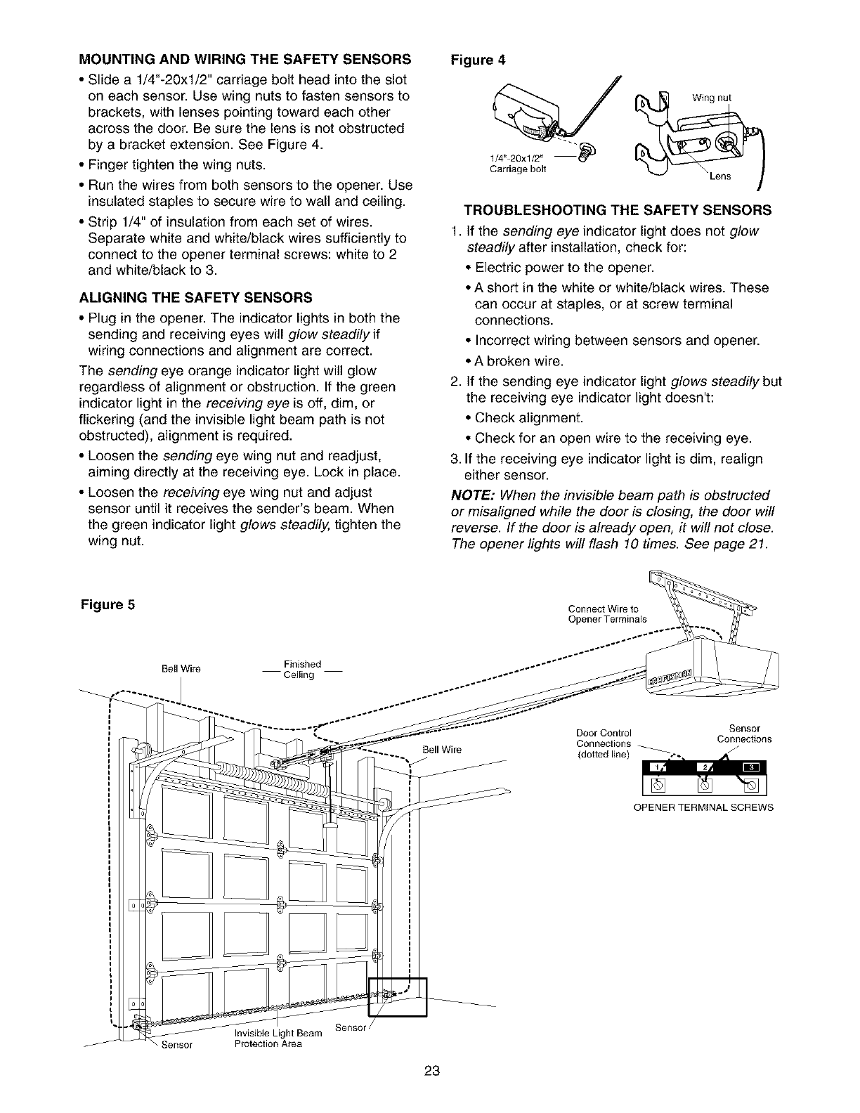
MOUNTING AND WIRING THE SAFETY SENSORS
• Slide a 1/4"-20xl/2" carriage bolt head into the slot
on each sensor. Use wing nuts to fasten sensors to
brackets, with lenses pointing toward each other
across the door. Be sure the lens is not obstructed
by a bracket extension. See Figure 4.
• Finger tighten the wing nuts.
• Run the wires from both sensors to the opener. Use
insulated staples to secure wire to wall and ceiling.
• Strip 1/4" of insulation from each set of wires.
Separate white and white/black wires sufficiently to
connect to the opener terminal screws: white to 2
and white/black to 3.
ALIGNING THE SAFETY SENSORS
• Plug in the opener. The indicator lights in both the
sending and receiving eyes will glow steadily if
wiring connections and alignment are correct.
The sending eye orange indicator light will glow
regardless of alignment or obstruction. If the green
indicator light in the receiving eye is off, dim, or
flickering (and the invisible light beam path is not
obstructed), alignment is required.
• Loosen the sending eye wing nut and readjust,
aiming directly at the receiving eye. Lock in place.
• Loosen the receiving eye wing nut and adjust
sensor until it receives the sender's beam. When
the green indicator light glows steadily, tighten the
wing nut.
Figure 4
1/4"-20xl/2"-"_
Carriage belt
Wing nut
TROUBLESHOOTING THE SAFETY SENSORS
1, If the sending eye indicator light does not glow
steadily after installation, check for:
• Electric power to the opener.
• A short in the white or white/black wires. These
can occur at staples, or at screw terminal
connections.
• Incorrect wiring between sensors and opener.
• A broken wire.
2, If the sending eye indicator light glows steadily but
the receiving eye indicator light doesn't:
• Check alignment.
• Check for an open wire to the receiving eye.
3. If the receiving eye indicator light is dim, realign
either sensor.
NOTE: When the invisible beam path is obstructed
or misaligned while the door is closing, the door will
reverse. If the door is already open, it will not close.
The opener lights will flash 10 times. See page 21.
Figure 5 Connect Wire to
Opener Terminals
Beil Wire Finished
Ceiting
Bell Wire
Door Control Sensor
Conneclions _ Connections
(dotted line) _ /
OPENER TERMINAL SCREWS
Invisible Light Beam
Sensor Proteclion Area
SenSOl
23
INSTALLATION STEP 1 1
Fasten the Door Bracket
Follow instructions which apply to your door type
as illustrated below or on the following page.
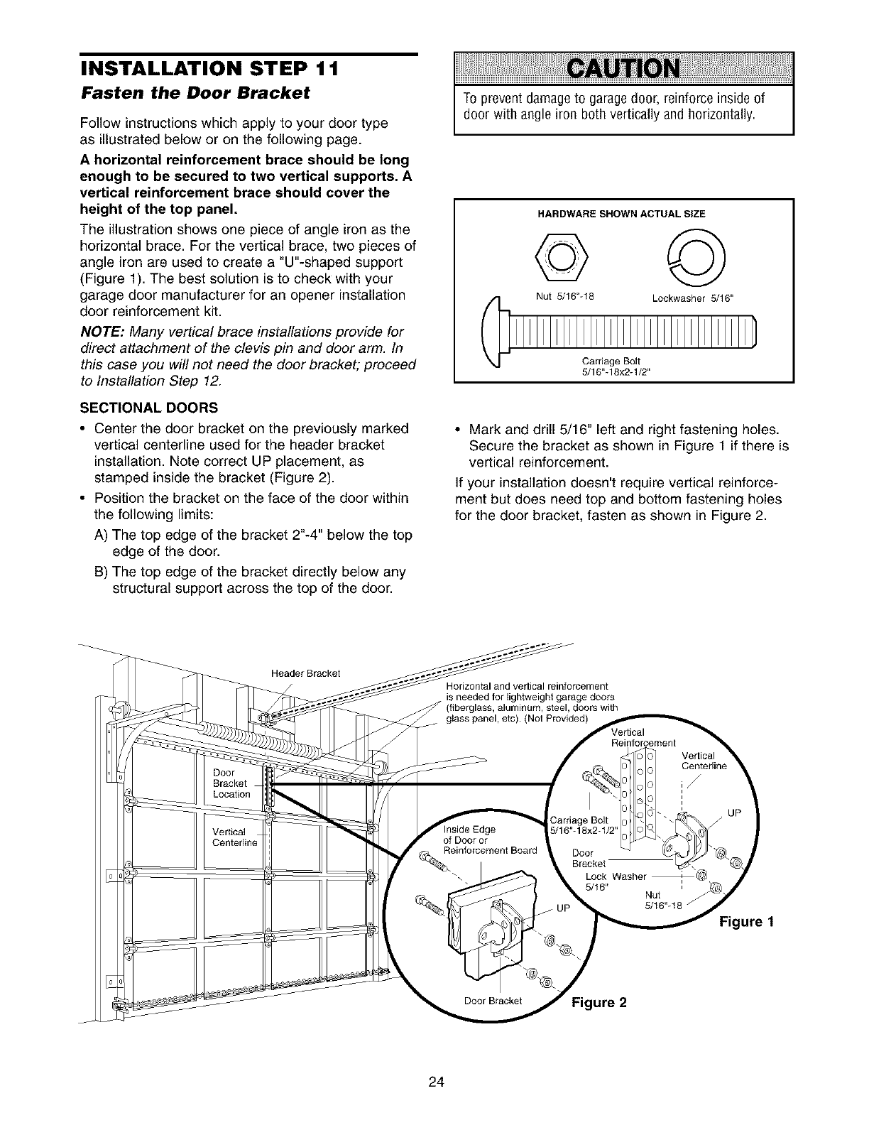
A horizontal reinforcement brace should be long
enough to be secured to two vertical supports A
vertical reinforcement brace should cover the
height of the top panel
The illustrationshows one piece of angle iron as the
horizontal brace. For the vertical brace, two pieces of
angle iron are used to create a "U"-shaped support
(Figure 1). The best solution is to check with your
garage door manufacturer for an opener installation
door reinforcement kit.
NOTE: Many vertical brace installations provide for
direct attachment of the clevis pin and door arm. In
this case you will not need the door bracket; proceed
to Installation Step 12.
SECTIONAL DOORS
•Center the door bracket on the previously marked
vertical centerline used for the header bracket
installation. Note correct UP placement, as
stamped inside the bracket (Figure 2).
• Position the bracket on the face of the door within
the following limits:
A) The top edge of the bracket 2"-4" below the top
edge of the door.
B) The top edge of the bracket directly below any
structural support across the top of the door.
To prevent damage to garagedoor, reinforce inside of
door with angle iron both vertically and horizontally.
HARDWARE SHOWN ACTUAL SIZE
© ©
Nut 5/16"-18 Lockwasher 5/16"
Carriage Bolt
5/16"q8x2q/2"
• Mark and drill 5/16" left and right fastening holes.
Secure the bracket as shown in Figure 1 if there is
vertical reinforcement.
If your installation doesn't require vertical reinforce-
ment but does need top and bottom fastening holes
for the door bracket, fasten as shown in Figure 2.
HeaderBraokel
Horizontal and vertical reinforcement
is needed for lightweight garage doors
(fiberglass, aluminum, steel, doors with
Figure 1
ure 2
24
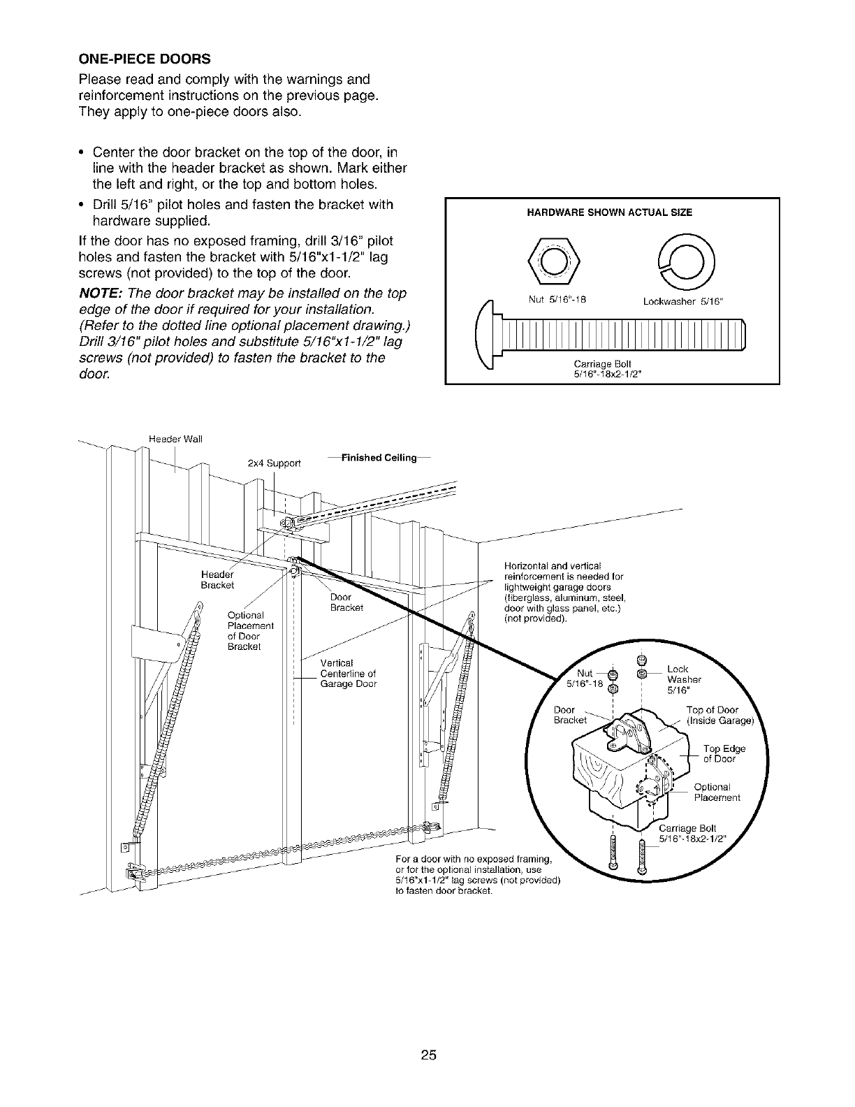
ONE-PIECEDOORS
Please read and comply with the warnings and
reinforcement instructions on the previous page.
They apply to one-piece doors also.
• Center the door bracket on the top of the door, in
line with the header bracket as shown. Mark either
the left and right, or the top and bottom holes.
• Drill 5/16" pilot holes and fasten the bracket with
hardware supplied.
If the door has no exposed framing, drill 3/16" pilot
holes and fasten the bracket with 5/16"x1-1/2" lag
screws (not provided) to the top of the door.
NOTE: The door bracket may be installed on the top
edge of the door if required for your installation.
(Refer to the dotted line optional placement drawing.)
Drill 3/16" pilot holes and substitute 5/16"xl-1/2" lag
screws (not provided) to fasten the bracket to the
door.
HARDWARE SHOWN ACTUAL SIZE
© ©
Nut 5/16"_18 Loekwasher 5/16"
Carriage Bolt
5/f 6"-f 8x2q/2"
Header Wall
2x4Suppo_ Finished Ceiling
Horizontal and verlical
reinforcement is needed for
lightweight garage doors
(fiberglass, aluminum, steel,
door with glass panel, etc.)
(not provided).
For a door with no exposed framing,
or for the optional installation, use
5/f 6"xlq/2" lag screws (not provided)
to fasten door bracket.
25
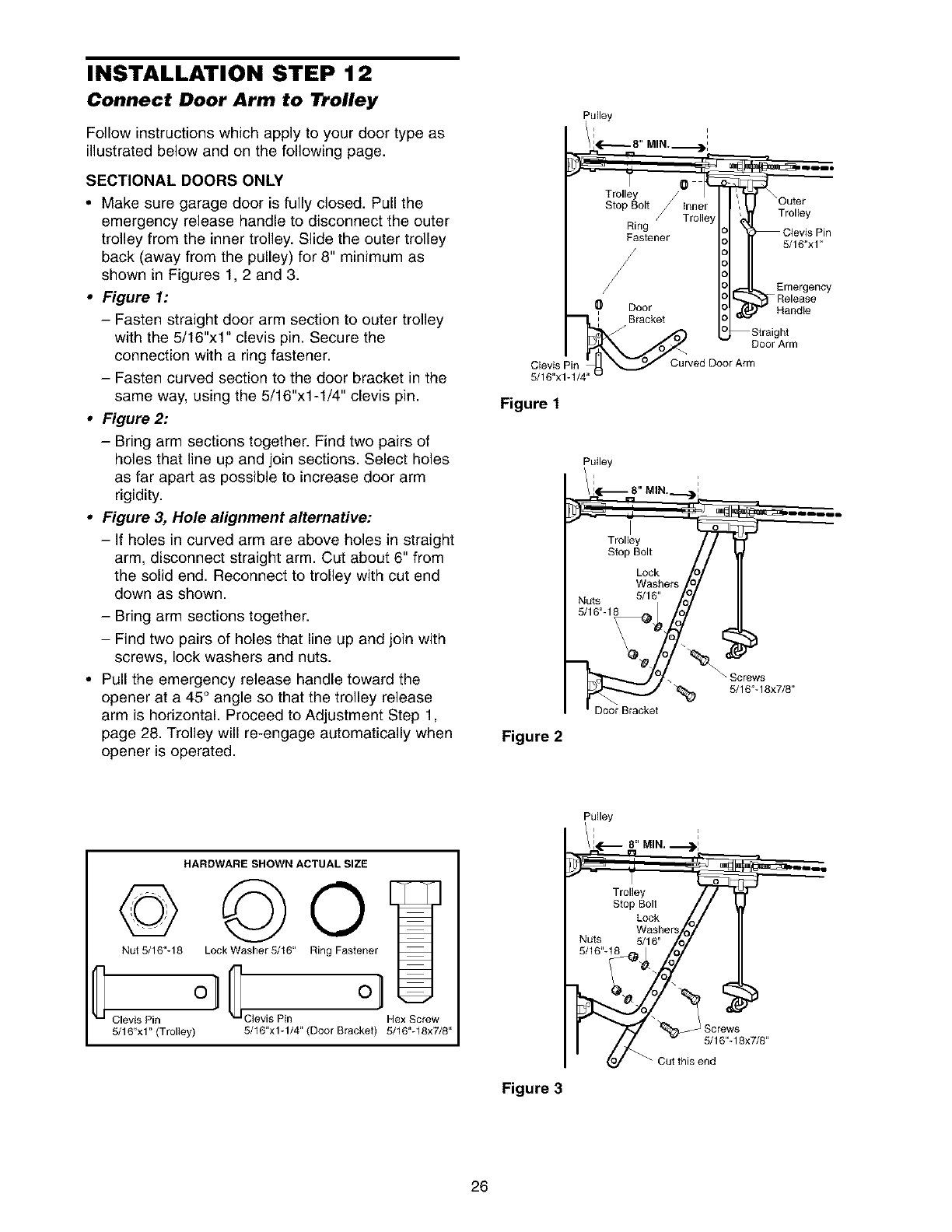
INSTALLATION STEP 12
Connect Door Arm to Trolley
Follow instructions which apply to your door type as
illustrated below and on the following page.
SECTIONAL DOORS ONLY
•Make sure garage door is fully closed. Pull the
emergency release handle to disconnect the outer
trolley from the inner trolley. Slide the outer trolley
back (away from the pulley) for 8" minimum as
shown in Figures 1, 2 and 3.
•Figure 1:
- Fasten straight door arm section to outer trolley
with the 5/16"xl" clevis pin. Secure the
connection with a ring fastener.
- Fasten curved section to the door bracket in the
same way, using the 5/16"x1-1/4" clevis pin.
•Figure 2:
-Bring arm sections together. Find two pairs of
holes that line up and join sections. Select holes
as far apart as possible to increase door arm
rigidity.
•Figure 3, Hole alignment alternative:
-If holes in curved arm are above holes in straight
arm, disconnect straight arm. Cut about 6" from
the solid end. Reconnect to trolley with cut end
down as shown.
-Bring arm sections together.
-Find two pairs of holes that line up and join with
screws, lock washers and nuts.
• Pull the emergency release handle toward the
opener at a 45° angle so that the trolley release
arm is horizontal. Proceed to Adjustment Step 1,
page 28. Trolley will re-engage automatically when
opener is operated.
Pulley
i i
'#¢-_- 8" MIN.._:
Stop Bolt inner , Outer
/Trolley _!!!_iii
Ring .
Ciev_s Pun
Fastener 5/16"xl"
Release
0 Door _ Relne_Se
:Bracket
1P._U rv Straight
Door Arm
Figure 1
Figure 2
MIN..
Screws
"_ 5/16"q 8x7/8"
Door Bracket
HARDWARE SHOWN ACTUAL SIZE
©©0'
Nut 5/16"-18 Lock Washer 5/16" Ring Fastener
G ol
Clevis Pin Clevis Pin Hex Screw
5/16"x1" (Trolley) 5/16"xlq/4" (Door Bracket) 5/16"-18x7/8"
Figure 3
Pulley
/! 0.,. !
_-.- n' .---._!
Trolle_!y 1
Stop :;'k
Washers
Nuts 5/16"
5/16"
5S/_r6.q8x7/8 ,,
26
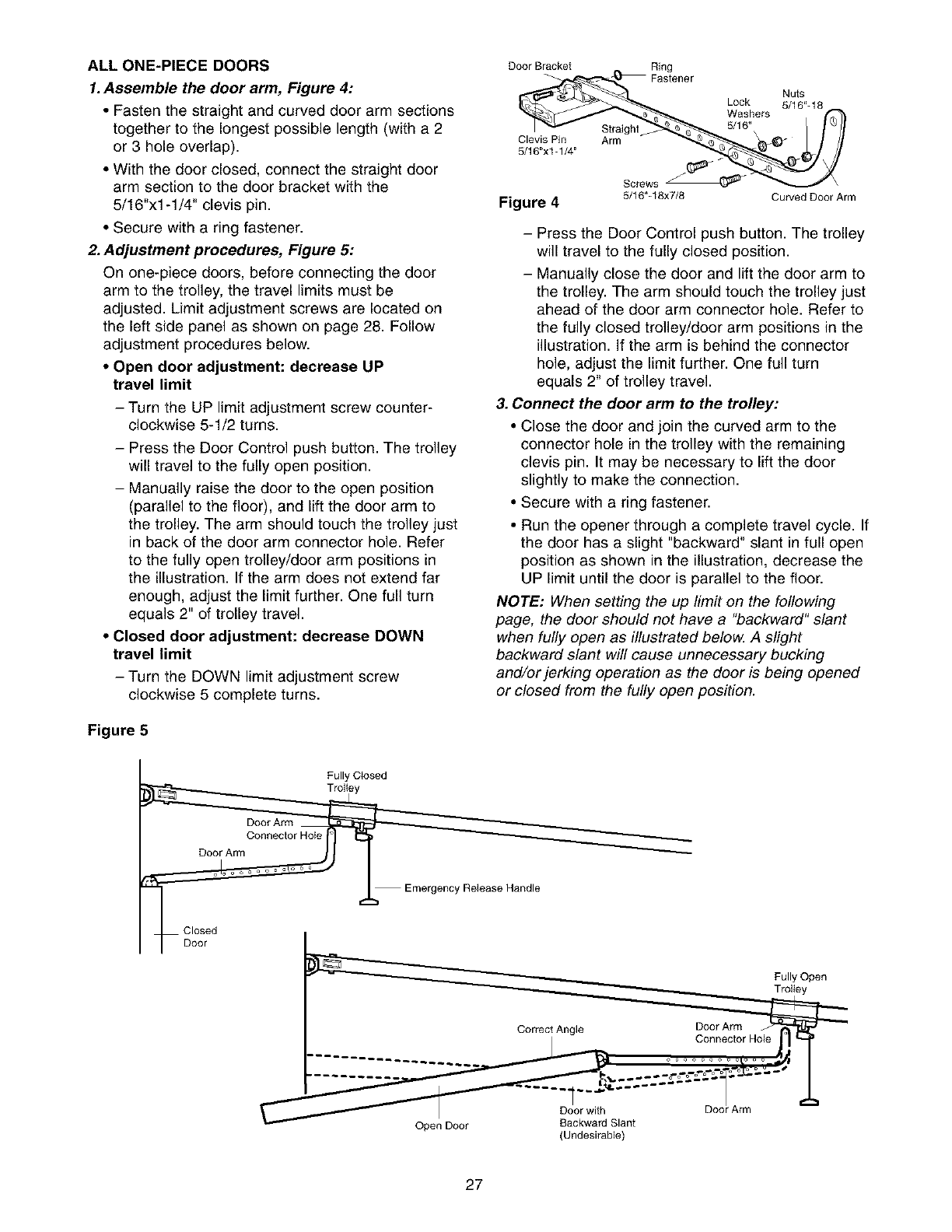
ALL ONE-PIECE DOORS
1. Assemble the door arm, Figure 4:
• Fasten the straight and curved door arm sections
together to the longest possible length (with a 2
or 3 hole overlap).
• With the door closed, connect the straight door
arm section to the door bracket with the
5/16"x1-1/4" clevis pin.
• Secure with a ring fastener.
2. Adjustment procedures, Figure 5:
On one-piece doors, before connecting the door
arm to the trolley, the travel limits must be
adjusted. Limit adjustment screws are located on
the left side panel as shown on page 28. Follow
adjustment procedures below.
• Open door adjustment: decrease UP
travel limit
- Turn the UP limit adjustment screw counter-
clockwise 5-1/2 turns.
-Press the Door Control push button. The trolley
will travel to the fully open position.
- Manually raise the door to the open position
(parallel to the floor), and lift the door arm to
the trolley. The arm should touch the trolley just
in back of the door arm connector hole. Refer
to the fully open trolley/door arm positions in
the illustration. If the arm does not extend far
enough, adjust the limit further. One full turn
equals 2" of trolley travel.
• Closed door adjustment: decrease DOWN
travel limit
- Turn the DOWN limit adjustment screw
clockwise 5 complete turns.
Figure 5
Door Bracket _ Ring
Fastener
Lock 5/16"-18
Washers
5/16"
5116"xi -I/4" Screws _r-_
r,g":-ure 45/16"-18x7/8 Curved Door Arm
- Press the Door Control push button. The trolley
will travel to the fully closed position.
- Manually close the door and lift the door arm to
the trolley. The arm should touch the trolley just
ahead of the door arm connector hole. Refer to
the fully closed trolley/door arm positions in the
illustration. If the arm is behind the connector
hole, adjust the limit further. One full turn
equals 2" of trolley travel.
3. Connect the door arm to the trolley:
• Close the door and join the curved arm to the
connector hole in the trolley with the remaining
clevis pin. It may be necessary to lift the door
slightly to make the connection.
• Secure with a ring fastener.
• Run the opener through a complete travel cycle. If
the door has a slight "backward" slant in full open
position as shown in the illustration, decrease the
UP limit until the door is parallel to the floor.
NOTE: When setting the up limit on the following
page, the door should not have a "backward" slant
when fully open as illustrated below. A slight
backward slant will cause unnecessary bucking
and/or jerking operation as the door is being opened
or closed from the fully open position.
Fully Closed
Trolley
Door Arm
Connector Hole
Door Arm
Emergency Release Handle
Closed
(Undesirable)
27
ADJUSTMENT STEP 1
Adjust the UP and DOWN Travel
Limits
Limit adjustment settings regulate the points at which
the door will stop when moving up or down.
To operate the opener, press the Door Control push
button. Run the opener through a complete travel
cycle.
• Does the door open and close completely?
• Does the door stay closed and not reverse
unintentionally when fully closed?
If your door passes both of these tests, no limit
adjustments are necessary unless the reversing test
fails (see Adjustment Step 3, page 30).
Adjustment procedures are outlined below. Read the
procedures carefully before proceeding to
Adjustment Step 2. Use a screwdriver to make limit
adjustments. Run the opener through a complete
travel cycle after each adjustment.
NOTE: Repeated operation of the opener during
adjustment procedures may cause the motor to
overheat and shut off. Simply wait 15 minutes and
try again.
NOTE: If anything interferes with the door's upward
travel, it will stop. If anything interferes with the
door's downward travel (including binding or
unbalanced doors), it will reverse.
Without a properly installed safety reversalsystem,
persons (particularly small children) could be
SERIOUSLYINJUREDor KILLEDby a closing garage
door.
• Incorrect adjustment of garage door travel limits will
interfere with proper operation of safety reversal
system.
• If one control (force or travel limits) is adjusted, the
other control may also needadjustment.
• After ANY adjustments are made,the safety reversal
system MUST be tested. Door MUST reverseon
contact with one-inch high object (or 2x4 laid flat) on
floor.
To prevent damage to vehicles, besure fully open door
provides adequate clearance.
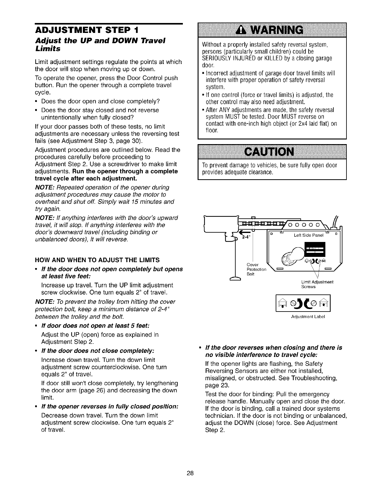
HOW AND WHEN TO ADJUST THE LIMITS
•If the door does not open completely but opens
at least five feet:
Increase up travel. Turn the UP limit adjustment
screw clockwise. One turn equals 2" of travel.
NOTE: To prevent the trolley from hitting the cover
protection bolt, keep a minimum distance of 2-4"
between the trolley and the bolt.
•If door does not open at least 5 feet:
Adjust the UP (open) force as explained in
Adjustment Step 2.
•If the door does not close completely:
Increase down travel. Turn the down limit
adjustment screw counterclockwise. One turn
equals 2" of travel.
If door still won't close completely, try lengthening
the door arm (page 26) and decreasing the down
limit.
•If the opener reverses in fully closed position:
Decrease down travel. Turn the down limit
adjustment screw clockwise. One turn equals 2"
of travel.
Cover
Protection
Boit
Limit Adjustment
Screws
Adjustment Label
If the door reverses when closing and there is
no visible interference to travel cycle:
If the opener lights are flashing, the Safety
Reversing Sensors are either not installed,
misaligned, or obstructed. See Troubleshooting,
page 23.
Test the door for binding: Pull the emergency
release handle. Manually open and close the door.
If the door is binding, call a trained door systems
technician. If the door is not binding or unbalanced,
adjust the DOWN (close) force. See Adjustment
Step 2.
28
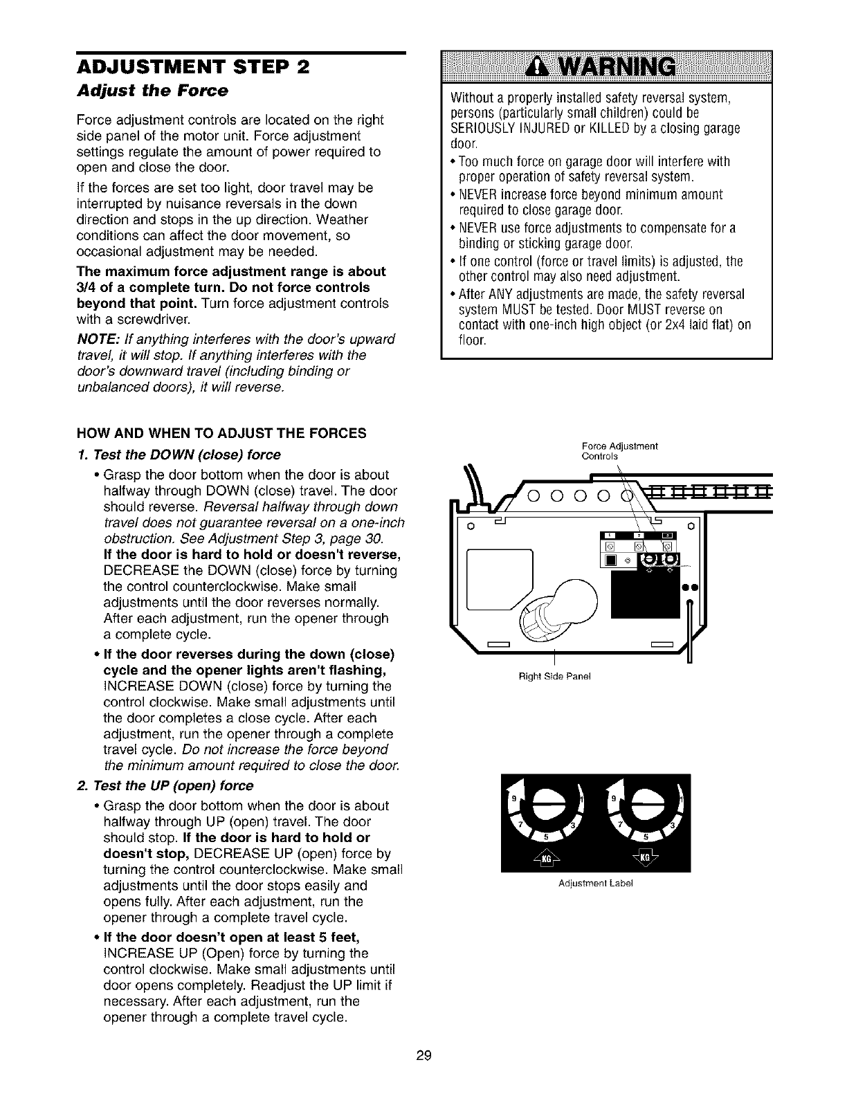
ADJUSTMENT STEP 2
Adjust the Force
Force adjustment controls are located on the right
side panel of the motor unit. Force adjustment
settings regulate the amount of power required to
open and close the door.
If the forces are set too light, door travel may be
interrupted by nuisance reversals in the down
direction and stops in the up direction. Weather
conditions can affect the door movement, so
occasional adjustment may be needed.
The maximum force adjustment range is about
3/4 of a complete turn. Do not force controls
beyond that point. Turn force adjustment controls
with a screwdriver.
NOTE: If anything interferes with the door's upward
travel, it will stop. If anything interferes with the
door's downward travel (including binding or
unbalanced doors), it will reverse.
Without a properly installed safety reversalsystem,
persons (particularly small children) could be
SERIOUSLYINJUREDor KILLEDby a closing garage
door.
• Too much force on garage door will interfere with
proper operation of safety reversalsystem.
• NEVERincreaseforce beyond minimum amount
required to close garage door.
• NEVERuse force adjustments to compensate for a
binding or sticking garage door.
• If one control (force or travel limits) is adjusted, the
other control may also needadjustment.
• After ANY adjustments are made,the safety reversal
system MUST be tested. Door MUST reverseon
contact with one-inch high object (or 2x4 laid flat) on
floor.
HOW AND WHEN TO ADJUST THE FORCES
1. Test the DOWN (close) force
• Grasp the door bottom when the door is about
halfway through DOWN (close) travel. The door
should reverse. Reversal halfway through down
travel does not guarantee reversal on a one-inch
obstruction. See Adjustment Step 3, page 30.
If the door is hard to hold or doesn't reverse,
DECREASE the DOWN (close) force by turning
the control counterclockwise. Make small
adjustments until the door reverses normally.
After each adjustment, run the opener through
a complete cycle.
• If the door reverses during the down (close)
cycle and the opener lights aren't flashing,
INCREASE DOWN (close) force by turning the
control clockwise. Make small adjustments until
the door completes a close cycle. After each
adjustment, run the opener through a complete
travel cycle. Do not increase the force beyond
the minimum amount required to close the door.
2. Test the UP (open) force
• Grasp the door bottom when the door is about
halfway through UP (open) travel. The door
should stop. If the door is hard to hold or
doesn't stop, DECREASE UP (open) force by
turning the control counterclockwise. Make small
adjustments until the door stops easily and
opens fully. After each adjustment, run the
opener through a complete travel cycle.
•If the door doesn't open at least 5 feet,
INCREASE UP (Open) force by turning the
control clockwise. Make small adjustments until
door opens completely. Readjust the UP limit if
necessary. After each adjustment, run the
opener through a complete travel cycle.
Force Adjustment
Controls
Right Side Panel
29
Adjustment Label
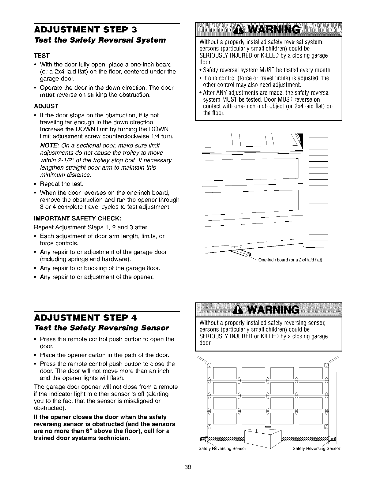
ADJUSTMENT STEP 3
Test the Safety Reversal System
TEST
•With the door fully open, place a one-inch board
(or a 2x4 laid flat) on the floor, centered under the
garage door.
• Operate the door in the down direction. The door
must reverse on striking the obstruction.
ADJUST
• If the door stops on the obstruction, it is not
traveling far enough in the down direction.
Increase the DOWN limit by turning the DOWN
limit adjustment screw counterclockwise 1/4 turn.
NOTE: On a sectional door, make sure limit
adjustments do not cause the trolley to move
within 2-1/2" of the trolley stop bolt. If necessary
lengthen straight door arm to maintain this
minimum distance.
• Repeat the test.
• When the door reverses on the one-inch board,
remove the obstruction and run the opener through
3 or 4 complete travel cycles to test adjustment.
IMPORTANT SAFETY CHECK:
Repeat Adjustment Steps 1, 2 and 3 after:
• Each adjustment of door arm length, limits, or
force controls.
• Any repair to or adjustment of the garage door
(including springs and hardware).
• Any repair to or buckling of the garage floor.
• Any repair to or adjustment of the opener.
Without a properly installed safety reversalsystem,
persons (particularly small children) could be
SERIOUSLYINJUREDor KILLEDby a closing garage
door.
• Safety reversal system MUST be tested every month.
• If one control (force or travel limits) is adjusted, the
other control may als0 needadjustment.
• After ANY adjustments are made,the safety reversal
system MUST be tested. Door MUST reverseon
contact with one-inch high object (or 2x4 laid flat) on
the floor.
J!
J
J
ADJUSTMENT STEP 4
Test the Safety Reversing Sensor
• Press the remote control push button to open the
door.
• Place the opener carton in the path of the door.
• Press the remote control push button to close the
door. The door will not move more than an inch,
and the opener lights will flash.
The garage door opener will not close from a remote
if the indicator light in either sensor is off (alerting
you to the fact that the sensor is misaligned or
obstructed).
If the opener closes the door when the safety
reversing sensor is obstructed (and the sensors
are no more than 6" above the floor), call for a
trained door systems technician.
Without a properly installed safety reversingsensor,
persons (particularly small children) could be
SERIOUSLYINJUREDor KILLEDby a closing garage
door.
Safety Reversing Sensor
3O
OPERATION
IMPORTANT SAFETY INSTRUCTIONS
To reduce the risk of severe injury or death:
1. READAND FOLLOWALL WARNINGSAND
INSTRUCTIONS.
2. ALWAYSkeep remote controls out of reach of children.
NEVERpermit children to operate or play with garage
door control push buttons or remote controls.
3. ONLYactivate garagedoor when it can be seenclearly, it
is properly adjusted, andthere are no obstructions to
door travel.
4. ALWAYSkeep garage door in sight until completely
closed. NO ONESHOULDCROSSTHEPATHOFTHE
MOVING DOOR.
5. NO ONESHOULDGOUNDERA STOPPED,PARTIALLY
OPENDOOR.
6. If possible, use emergency release handleto disengage
trolley ONLYwhen garagedoor is CLOSED.Weakor
broken springs or unbalanced door could result in an
open door falling rapidly and/or unexpectedly.
7. NEVERuse emergency releasehandle unless garage
doorway is clear of persons and obstructions.
8. NEVERuse handleto pull garagedoor open or closed. If
rope knot becomes untied, you could fall.
9. If one control (force or travel limits) is adjusted, the
other control may also needadjustment.
10. After ANY adjustments are made,the safety reversal
system MUST be tested.
11. Safety reversalsystem MUST be tested every month.
Garagedoor MUST reverseon contact with one-inch
(2.5 cm) high object (or a 2 x 4 laid flat) on the floor.
12. ALWAYSKEEPGARAGEDOORPROPERLYBALANCED
(see page 3). An improperly balanceddoor may not
reversewhen required and could result in SEVERE
INJURYor DEATH.
13. All repairs to cables, spring assemblies and other
hardware, all of which are under EXTREMEtension,
MUST be made by a trained door systems technician.
14. ALWAYSdisconnect electric power to garagedoor
opener BEFOREmaking any repairs or removing
covers.
15.SAVETHESE INSTRUCTIONS.
Using Your Garage Door Opener
Your Security+ opener and hand-held remote control
have been factory-set to a matching code which
changes with each use, randomly accessing over
100 billion new codes. Your opener will operate with
up to eight Security+ remote controls and one
Security÷ Keyless Entry System. If you purchase a
new remote, or if you wish to deactivate any remote,
follow the instructions in the Programming section.
Activate your opener with any of the following:
•The hand-held Remote Control: Hold the large
push button down until the door starts to move.
• The wall-mounted Door Control: Hold the push
button down until the door starts to move.
• The Keyless Entry (See Accessories): If provided
with your garage door opener, it must be
programmed before use. See Programming.
When the opener is activated (with the safety
reversing sensor correctly installed and aligned)
1. If open, the door will close. If closed, it will open.
2. If closing, the door will reverse.
3. If opening, the door will stop.
4. If the door has been stopped in a partially open
position, it will close.
5. If obstructed while closing, the door will reverse. If
the obstruction interrupts the sensor beam, the
opener lights will blink for five seconds.
6. If obstructed while opening, the door will stop.
7. If fully open, the door will not close when the beam
is broken. The sensor has no effect in the opening
cycle.
If the sensor is not installed, or is misaligned, the
door won't close from a hand-held remote. However,
you can close the door with the Door Control, the
Outdoor Key Switch, or Keyless Entry, if you activate
them until down travel is complete. If you release
them too soon, the door will reverse.
The opener lights will turn on under the following
conditions: when the opener is initially plugged in;
when power is restored after interruption; when the
opener is activated.
They will turn off automatically after 4-1/2 minutes or
provide constant light when the Light feature on the
Premium Control Console is activated. Bulb size is
75 watts maximum.
Security÷ Light Feature: Lights will also turn on
when someone walks through the open garage door.
With a Premium Control Console, this feature may be
turned off as follows: With the opener lights off, press
and hold the light button for 10 seconds, until the
light goes on and off again. To restore this feature,
start with the opener lights on, then press and hold
the light button for 10 seconds until the light goes off,
then on again.
31
Using the WaU.Mounted To Open the Door Manually
Door Control
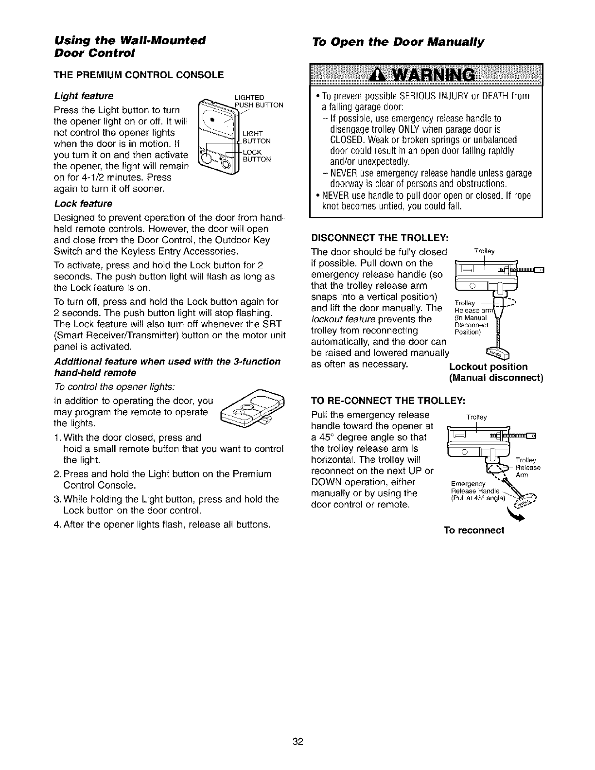
THE PREMIUM CONTROL CONSOLE
Light feature
Press the Light button to turn I-f_
the opener light on or off. It will
not control the opener lights
when the door is in motion. If
you turn it on and then activate
the opener, the light will remain
on for 4-1/2 minutes. Press
again to turn it off sooner.
LIGHTED
PUSH BUTTON
LIGHT
B_iTTON
LOCK
TTON
Lock feature
Designed to prevent operation of the door from hand-
held remote controls. However, the door will open
and close from the Door Control, the Outdoor Key
Switch and the Keyless Entry Accessories.
To activate, press and hold the Lock button for 2
seconds. The push button light will flash as long as
the Lock feature is on.
To turn off, press and hold the Lock button again for
2 seconds. The push button light will stop flashing.
The Lock feature will also turn off whenever the SRT
(Smart Receiver/Transmitter) button on the motor unit
panel is activated.
Additional feature when used with the 3-function
hand-held remote
To control the opener lights:
In addition to operating the door, you /._
may program the remote to operate
the lights.
1. With the door closed, press and
hold a small remote button that you want to control
the light.
2. Press and hold the Light button on the Premium
Control Console.
3. While holding the Light button, press and hold the
Lock button on the door control.
4. After the opener lights flash, release all buttons.
• To prevent possible SERIOUSINJURYor DEATHfrom
a falling garagedoor:
- If possible, use emergency release handleto
disengagetrolley ONLYwhen garage door is
CLOSED.Weakor broken springs or unbalanced
door could result in an open door falling rapidly
and/or unexpectedly.
- NEVERuse emergency releasehandle unless garage
doorway is clear of persons and obstructions.
• NEVERusehandleto pull door open or closed. If rope
knot becomes untied, you could fall.
DISCONNECTTHETROLLEY:
The door should be fully closed
if possible. Pull down on the
emergency release handle (so
that the trolley release arm
snaps into a vertical position)
and lift the door manually. The
lockout feature prevents the
trolley from reconnecting
automatically, and the door can
be raised and lowered manually
as often as necessary.
Trolley
_I
Trolley ..j
Release am
(In Manual
Disconnect
Posilion)
Lockout position
(Manual disconnect)
TO RE-CONNECT THE TROLLEY:
Pull the emergency release Troltey
handle toward the opener at _I_IY
a 45° degree angle so that
the trolley release arm is
horizontal. The trolley will Trolley
reconnect on the next UP or Release
DOWN operation, either Emergency "__
Release Handlee)-_,/_manually or by using the (Pullat45Oangl_.._, "#
door control or remote.
To reconnect
32
Care of Your Opener THE REMOTE CONTROL BATTERY
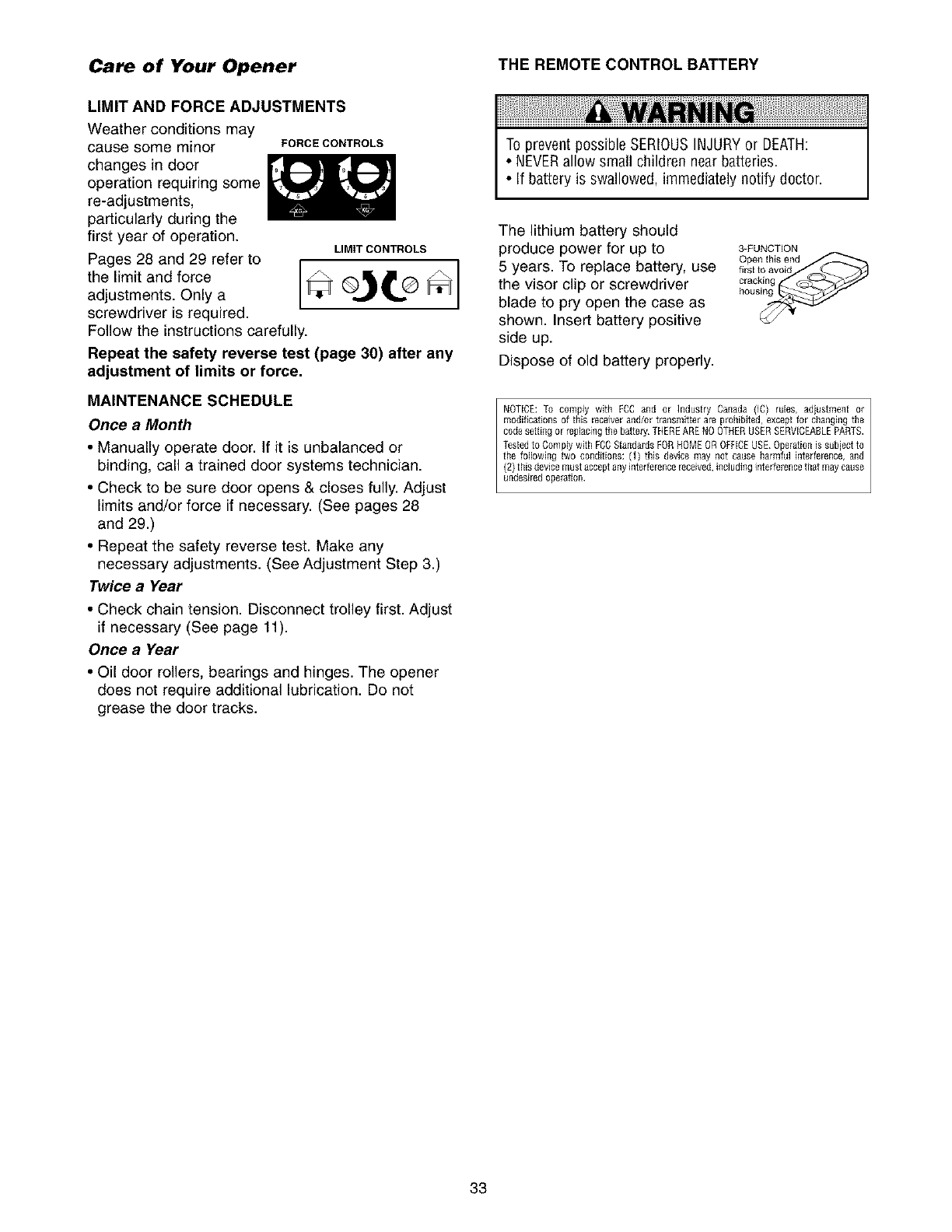
LIMIT AND FORCE ADJUSTMENTS
Weather conditions may
cause some minor
changes in door
operation requiring some
re-adjustments,
particularly during the
first year of operation.
Pages 28 and 29 refer to
the limit and force
adjustments. Only a
screwdriver is required.
FORCE CONTROLS
LIMIT CONTROLS
Follow the instructions carefully.
Repeat the safety reverse test (page 30) after any
adjustment of limits or force.
MAINTENANCE SCHEDULE
Once a Month
• Manually operate door. If it is unbalanced or
binding, call a trained door systems technician.
• Check to be sure door opens & closes fully. Adjust
limits and/or force if necessary. (See pages 28
and 29.)
• Repeat the safety reverse test. Make any
necessary adjustments. (See Adjustment Step 3.)
Twice a Year
• Check chain tension. Disconnect trolley first. Adjust
if necessary (See page 11).
Once a Year
• Oil door rollers, bearings and hinges. The opener
does not require additional lubrication. Do not
grease the door tracks.
To prevent possible SERIOUSINJURYor DEATH:
• NEVERallow small children near batteries.
• If battery is swallowed, immediately notify doctor.
The lithium battery should
produce power for up to
5 years. To replace battery, use
the visor clip or screwdriver
blade to pry open the case as
shown. Insert battery positive
side up.
Dispose of old battery properly.
3-FUNCTION
Open this end
first to avoid
cracking
NOTICE: To comply with Fog and or Industry Canada (IC) rules, adjustment or
modifications of this [eceiver and/or transmitter are prohibited, except for changingthe
code setting or replacingthe battery THEREARENOOTHERUSERSERVICEABLEPARTS.
Testedto Comply with FCCStandardsFORHOMEOR OffiCE USE Operationis subject to
the following two conditions: (1) this device may not cause harmful interference, and
(2) this devicemust acceptanyinterference_eceived,includinginterferencethat may cause
undesiredoperation
33
Having a Problem?
I. The opener doesn't operate from either the Door
Control or the remote control:
•Does the opener have electric power? Plug a lamp into the
outlet. If it doesn't light, check the fuse box or the circuit
breaker. (Some outlets are controlled by a wall switch.)
• Have you disabled all door locks? Review installation
instruction warnings on page 11.
• Is there a build-up of ice or snow under the door? The door
may be frozen to the ground. Remove any restriction.
• The garage door spring may be broken. Have it replaced.
• Repeated operation may have tripped the overload
protector in the motor. Wait 15 minutes and try again.
2. Opener operates from the remote, but not from the
Door Control:
• Is the door control lit? If not, remove the bell wire from the
motor unit terminals. Short the red and white terminals by
touching both terminals at the same time with a piece of
wire. If the opener runs, check for a faulty wire connection
at the door control, a short under the staples, or a broken
wire.
• Are the wiring connections correct? Review Installation
Step 6, page 18.
3. The door operates from the Door Control, but not from
the remote controh
• Is the door push button flashing? If your model has the
Lock feature, make sure it is off.
• Program the opener to match the remote control code.
(Refer to instructions on the motor unit panel.) Repeat with
all remotes.
4 The remote control has short range:
• Change the location of the remote control in your car.
• Check to be sure the antenna on the side or back panel of
motor unit extends fully downward.
• Some installations may have shorter range due to a metal
door, foil backed insulation, or metal garage siding.
(Antenna Extender Kit 41A3504)
5, Opener noise is disturbing in living quarters of home:
• If operational noise is a problem because of proximity of
the opener to the living quarters, the Vibration Isolator Kit
41A3263 can be installed. This kit was designed to
minimize vibration to the house and is easy to install.
6 The garage door opens and closes by itself:
• Be sure that all remote control push buttons are off.
• Remove the bell wire from the door control terminals and
operate from the remote only. If this solves the problem, the
door control is faulty (replace), or there is an intermittent short
on the wire between the door control and the motor unit.
• Clear memory and re-program all remote controls.
7. The door doesn't open completely:
• Is something obstructing the door? Is it out of balance, or
are the springs broken? Remove the obstruction or repair
the door.
• If the door is in good working order but now doesn't open
all the way, increase the up force. See Adjustment Step 2.
• If the door opens at least 5 feet, the travel limits may need
to be increased. One turn equals 2 inches of travel. See
Adjustment Step 1.
Repeat the safety reverse test after the adjustment is
complete.
8. The door stops but doesn't close completely:
• Review the travel limits adjustment procedures on page 28.
Repeat the safety reverse test after any adjustment of door
arm length, close force or down limit.
9. The door opens but won't close:
• If the opener lights blink, check the safety reversing sensor.
See Installation Step 10.
• If the opener lights don't blink and it is a new installation,
check the down force. See Adjustment Step 2, page 29.
For an existing installation, see below.
Repeat the safety reverse test after the adjustment is complete.
10. The door reverses for no apparent reason and opener
lights don't blink:
• Is something obstructing the door? Pull the emergency
release handle. Operate the door manually. If it is unbalanced
or binding, call a trained door systems technician.
• Clear any ice or snow from the garage floor area where
the door closes.
• Review Adjustment Step 2 on page 29.
• If door reverses in the fully closed position, decrease the
travel limits (Adjustment Step 1).
Repeat safety reverse test after adjustments to force or travel
limits. The need for occasional adjustment of the force and
limit settings is normal Weather conditions in particular can
affect door travel
11. The door reverses for no apparent reason and opener
lights blink for 5 seconds after reversing:
• Check the safety reversing sensor. Remove any obstruction
or align the receiving eye. See Installation Step 10.
12. The opener lights don't turn on:
• Replace the light bulbs (75 watts maximum). Use a standard
neck garage door opener bulb if regular bulb burns out.
13. The opener lights don't turn off:
• Is the Light feature on? Turn it off.
14. The opener strains or maximum force is needed to
operate door:
• The door may be out of balance or the springs may be
broken. Close the door and use the emergency release
handle to disconnect the trolley. Open and close the door
manually. A properly balanced door will stay in any point of
travel while being supported entirely by its springs. If it
does not, disconnect the opener and call a trained door
systems technician. Do not increase the force to operate
the opener.
15. The opener motor hums briefly, then won't work:
• The garage door springs may be broken. See above.
• If the problem occurs on the first operation of the opener,
door may be locked. Disable the door lock. If the chain was
removed and reinstalled, the motor may be out of phase.
Remove the chain; cycle the motor to the down position.
Observe the drive sprocket. When it turns in a clockwise
direction and stops in the down position, reinstall the chain.
Repeat the safety reverse test after the adjustment is
complete.
16. The opener won't operate due to power failure:
• Use the emergency release handle to disconnect the
trolley. The door can be opened and closed manually.
When power is restored, press the Door Control push
button and trolley will automatically reconnect (unless
trolley is in lockout position.) See page 32.
• The Emergency Key Release accessory (for use on
garages with no service door) disconnects the trolley from
outside the garage in case of power failure.
17. The chain droops or sags:
• It is normal for the chain to droop slightly in the closed door
position. Use the emergency release to disconnect the
trolley. If the chain returns to normal height when the trolley
is disengaged and the door reverses on a one-inch board,
no adjustments are needed (see page 11).
34
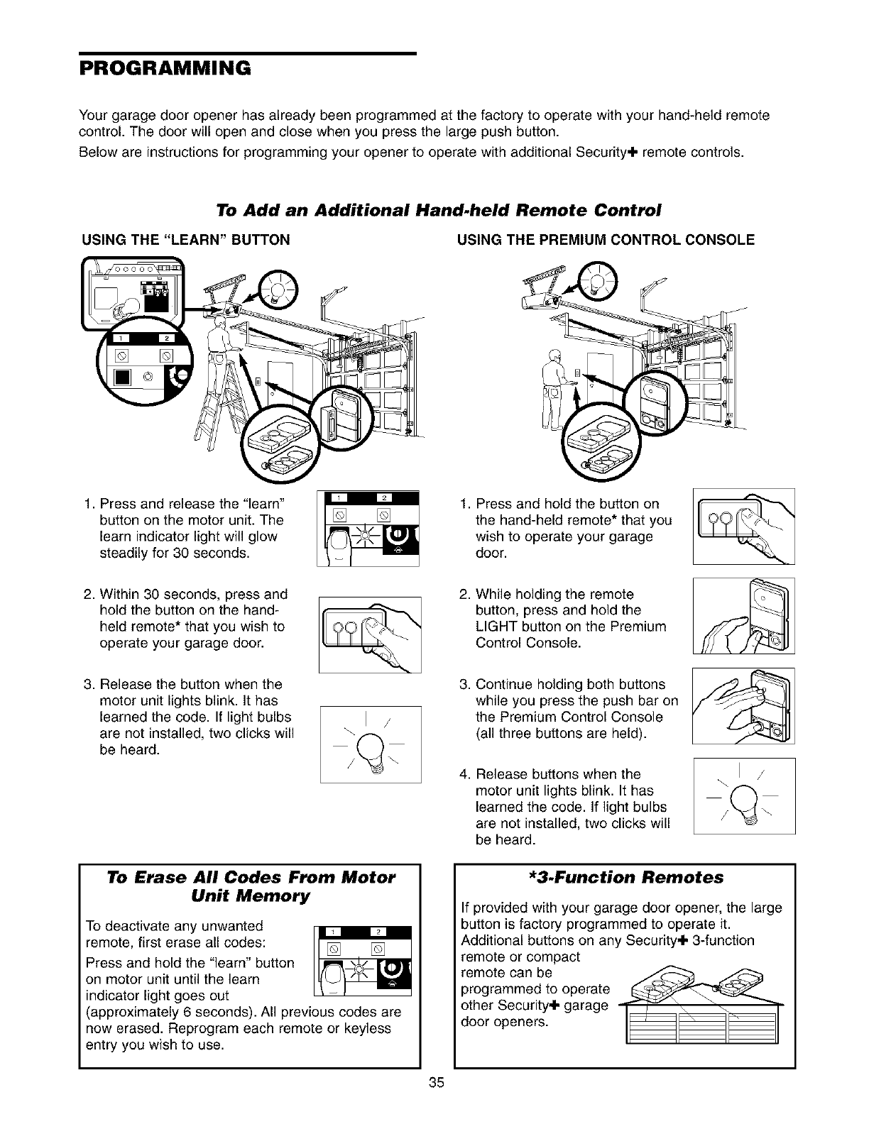
PROGRAMMING
Your garage door opener has already been programmed at the factory to operate with your hand-held remote
control. The door will open and close when you press the large push button.
Below are instructions for programming your opener to operate with additional Security÷ remote controls.
To Add an Additional Hand.held Remote Control
USING THE "LEARN" BUTTON USING THE PREMIUM CONTROL CONSOLE
1. Press and release the "learn"
button on the motor unit. The
learn indicator light will glow
steadily for 30 seconds.
2. Within 30 seconds, press and
hold the button on the hand-
held remote* that you wish to
operate your garage door.
3. Release the button when the
motor unit lights blink. It has
learned the code. If light bulbs
are not installed, two clicks will
be heard.
\1 /
1, Press and hold the button on
the hand-held remote* that you
wish to operate your garage
door.
2, While holding the remote
button, press and hold the
LIGHT button on the Premium
Control Console.
,Continue holding both buttons
while you press the push bar on
the Premium Control Console
(all three buttons are held).
4, Release buttons when the
motor unit lights blink. It has
learned the code. If light bulbs
are not installed, two clicks will
be heard.
\1 /
To Erase All Codes From Motor
Unit Memory
To deactivate any unwanted
remote, first erase all codes:
Press and hold the "learn" button
on motor unit until the learn
indicator light goes out
(approximately 6 seconds). All previous codes are
now erased. Reprogram each remote or keyless
entry you wish to use.
*3.Function Remotes
If provided with your garage door opener, the large
button is factory programmed to operate it.
Additional buttons on any Security÷ 3-function
remote or compact
remote can be _ _
programmed to operate
other Security÷ garage
door openers.
35
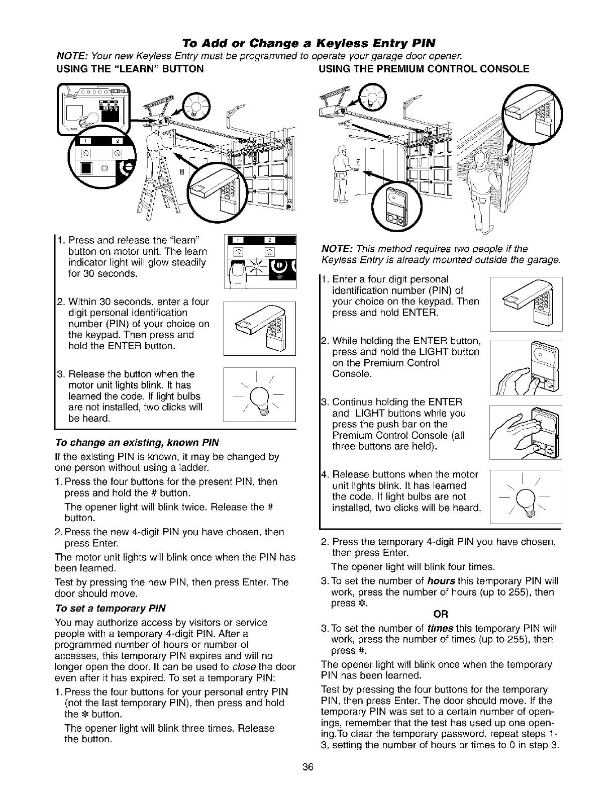
To Add or Change a Keyless Entry PIN
NOTE: Your new Keyless Entry must be programmed to operate your garage door opener.
USING THE "LEARN" BUTTON USING THE PREMIUM CONTROL CONSOLE
1. Press and release the "learn"
button on motor unit. The learn
indicator light will glow steadily
for 30 seconds.
2. Within 30 seconds, enter a four
digit personal identification
number (PIN) of your choice on
the keypad• Then press and
hold the ENTER button•
\1 /
3. Release the button when the
motor unit lights blink. It has
learned the code. If light bulbs
are not installed, two clicks will
be heard•
To change an existing, known PIN
If the existing PIN is known, it may be changed by
one person without using a ladder•
1. Press the four buttons for the present PIN, then
press and hold the # button•
The opener light will blink twice• Release the #
button•
2. Press the new 4-digit PIN you have chosen, then
press Enter•
The motor unit lights will blink once when the PIN has
been learned•
Test by pressing the new PIN, then press Enter. The
door should move.
To set a temporary PiN
You may authorize access by visitors or service
people with a temporary 4-digit PIN. After a
programmed number of hours or number of
accesses, this temporary PIN expires and will no
longer open the door. It can be used to close the door
even after it has expired• To set a temporary PIN:
1. Press the four buttons for your personal entry PIN
(not the last temporary PIN), then press and hold
the • button•
The opener light will blink three times. Release
the button•
NOTE: This method requires two people if the
Keyless Entry is already mounted outside the garage.
• Enter a four digit personal
identification number (PIN) of
your choice on the keypad. Then
press and hold ENTER.
!. While holding the ENTER button,
press and hold the LIGHT button
on the Premium Control
Console.
3. Continue holding the ENTER
and LIGHT buttons while you
press the push bar on the
Premium Control Console (all
three buttons are held)•
4. Release buttons when the motor
unit lights blink. It has learned
the code. If light bulbs are not
installed, two clicks will be heard.
2. Press the temporary 4-digit PIN you have chosen,
then press Enter•
The opener light will blink four times.
3.To set the number of hoursthie temporary PIN will
work, press the number of hours (up to 255), then
press _=. OR
3. To set the number of times this temporary PIN will
work, press the number of times (up to 255), then
press #.
The opener light will blink once when the temporary
PIN has been learned•
Test by pressing the four buttons for the temporary
PIN, then press Enter. The door should move. If the
temporary PIN was set to a certain number of open-
ings, remember that the test has used up one open-
ing.To clear the temporary password, repeat steps 1-
3, setting the number of hours or times to 0 in step 3.
36
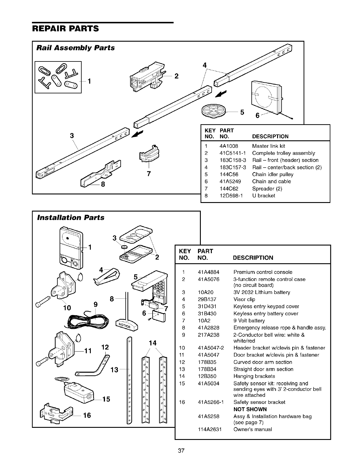
REPAIR PARTS
Rail Assembly Parts
3
'\\
7
4
KEY PART
NO. NO. DESCRIPTION
1
2
3
4
5
6
7
8
4A1008
41C5141-1
183C158-3
183C157-3
144C56
41A5249
144C62
12D598-1
Master link kit
Complete trolley assembly
Rail - front (header) section
Rail - center/back section (2)
Chain idler pulley
Chain and cable
Spreader (2)
U bracket
Installation Parts
KEY PART
NO. NO. DESCRIPTION
1
2
3
4
5
6
7
8
9
10
11
12
13
14
15
16
41A4884
41A5076
10A20
29B137
31D431
31B430
10A2
41A2828
217A238
41A5047-2
41A5047
178B35
178B34
12B350
41A5034
41A5266-1
41A5258
114A2631
Premium control console
3-function remote control case
(no circuit board)
3V 2032 Lithium battery
Visor clip
Keyless entry keypad cover
Keyless entry battery cover
9 Volt battery
Emergency release rope & handle assy.
2-Conductor bell wire: white &
white/red
Header bracket w/clevis pin & fastener
Door bracket w/clevis pin & fastener
Curved door arm section
Straight door arm section
Hanging brackets
Safety sensor kit: receiving and
sending eyes with 3' 2-conductor bell
wire attached
Safety sensor bracket
NOT SHOWN
Assy & Installation hardware bag
(see page 7)
Owner's manual
37
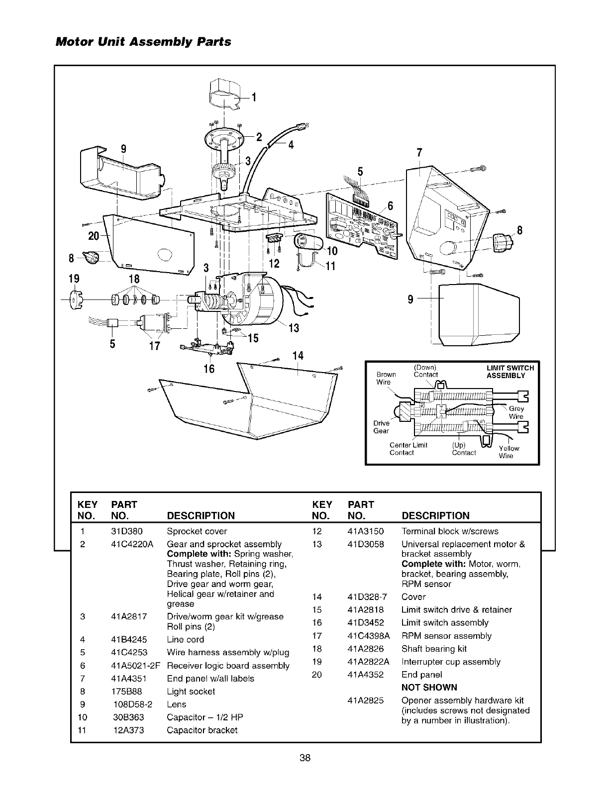
Motor Unit Assembly Parts
5
7
19 18
17
16
15 "13
14
(Down) LIMIT SWITCH
Brown Contact ASSEMBLY
Wire \
\
Wire
Gear
Center Limit (Up) Yellow
Contact Contact Wire
KEY PART KEY PART
NO. NO. DESCRIPTION NO. NO. DESCRIPTION
1 31D380 Sprocket cover 12 41A3150 Terminal block w/screws
2 41C4220A Gear and sprocket assembly 13 41D3058 Universal replacement motor &
Complete with: Spring washer, bracket assembly
Thrust washer, Retaining ring, Complete with: Motor, worm,
Bearing plate, Roll pins (2), bracket, bearing assembly,
Drive gear and worm gear, RPM sensor
Helical gear w/retainer and 14 41D328-7 Cover
grease 15 41A2818 Limit switch drive & retainer
3 41A2817 Drive/worm gear kit w/grease
Roll pins (2) 16 41D3452 Limit switch assembly
4 41B4245 Line cord 17 41C4398A RPM sensor assembly
5 41C4253 Wire harness assembly w/plug 18 41A2826 Shaft bearing kit
6 41A5021-2F Receiver logic board assembly 19 41A2822A Interrupter cup assembly
7 41A4351 End panel w/all labels 20 41A4352 End panel
8 175B88 Light socket NOT SHOWN
9 108D58-2 Lens 41A2825 Opener assembly hardware kit
(includes screws not designated
10 30B363 Capacitor - 1/2 HP by a number in illustration).
11 12A373 Capacitor bracket
38
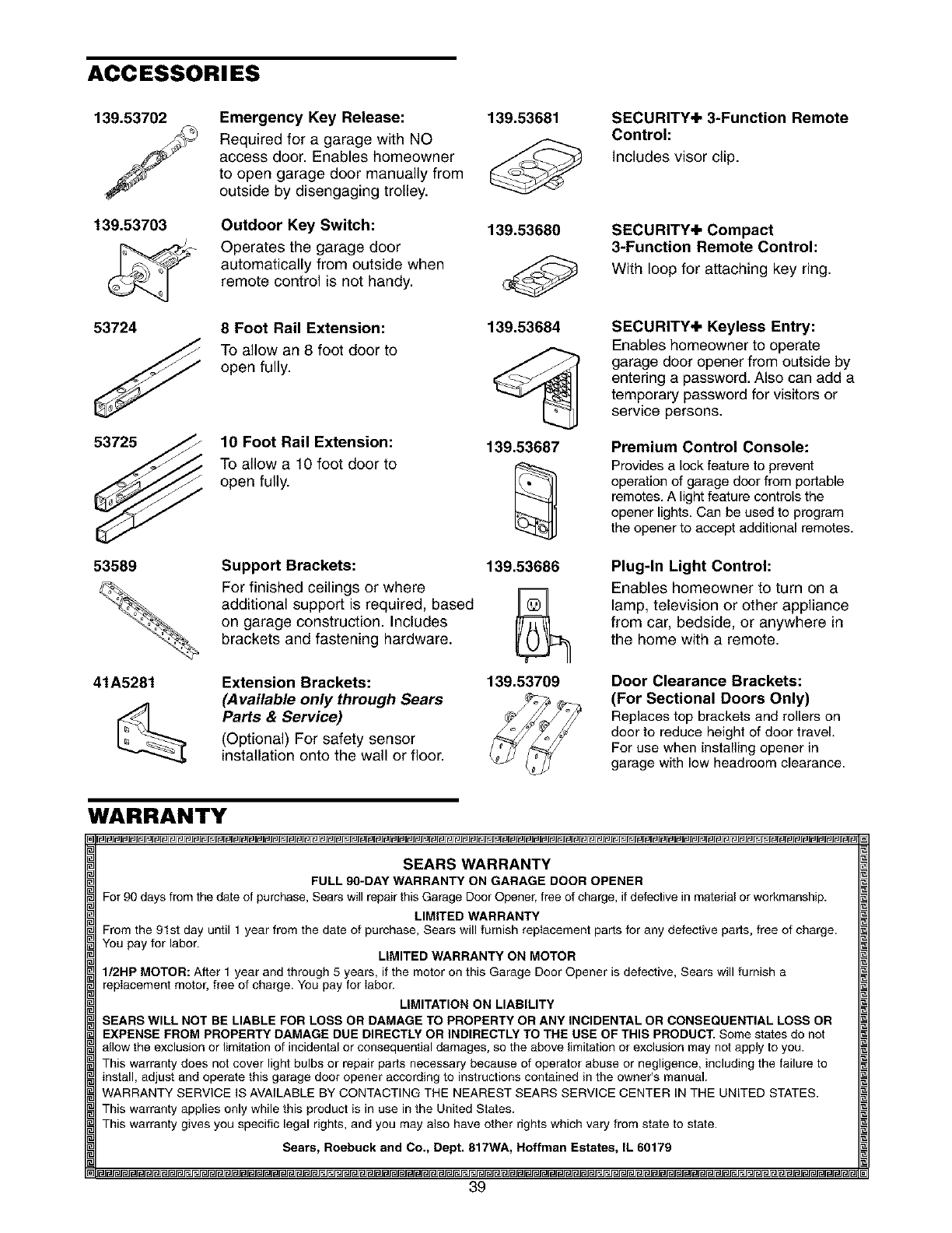
ACCESSORI ES
139.53702
139.53703
m-
53724
53725
53589
41A5281
Emergency Key Release:
Required for a garage with NO
access door. Enables homeowner
to open garage door manually from
outside by disengaging trolley.
Outdoor Key Switch:
Operates the garage door
automatically from outside when
remote control is not handy.
8Foot Rail Extension:
To allow an 8 foot door to
open fully.
10 Foot Rail Extension:
To allow a 10 foot door to
open fully.
Support Brackets:
For finished ceilings or where
additional support is required, based
on garage construction. Includes
brackets and fastening hardware.
Extension Brackets:
(Available only through Sears
Parts & Service)
(Optional) For safety sensor
installation onto the wall or floor.
139.53681
139.53680
139.53684
139.53687
139.53686
139.53709
SECURITY+ 3-Function Remote
Control:
Includes visor clip.
SECURITY+ Compact
3-Function Remote Control:
With loop for attaching key ring.
SECURITY+ Keyless Entry:
Enables homeowner to operate
garage door opener from outside by
entering a password. Also can add a
temporary password for visitors or
service persons.
Premium Control Console:
Provides a lock feature to prevent
operation of garage door from portable
remotes. A light feature controls the
opener lights. Can be used to program
the opener to accept additional remotes.
Plug-In Light Control:
Enables homeowner to turn on a
lamp, television or other appliance
from car, bedside, or anywhere in
the home with a remote.
Door Clearance Brackets:
(For Sectional Doors Only)
Replaces top brackets and rollers on
door to reduce height of door travel.
For use when installing opener in
garage with low headroom clearance.
WARRANTY
SEARS WARRANTY
FULL 90-DAY WARRANTY ON GARAGE DOOR OPENER
For 90 days from the date of purchase, Sears will repair this Garage Door Opener, free of charge, if defective in material or workmanship.
LIMITED WARRANTY
From the 91st day until 1 year from the date of purchase, Sears will furnish replacement parts for any defective parts, free of charge.
You pay for labor. LIMITED WARRANTY ON MOTOR
I/2HP MOTOR: After 1 year and through 5 years, if the motor on this Garage Door Opener is defective, Sears will furnish a
replacement motor, free of charge. You pay for labor.
LIMITATION ON LIABILITY
SEARS WILL NOT BE LIABLE FOR LOSS OR DAMAGE TO PROPERTY OR ANY INCIDENTAL OR CONSEQUENTIAL LOSS OR
EXPENSE FROM PROPERTY DAMAGE DUE DIRECTLY OR INDIRECTLY TO THE USE OF THIS PRODUCT. Some states do not
allow the exclusion or limitation of incidental or consequential damages, so the above limitation or exclusion may not apply to you.
This warranty does not cover light bulbs or repair parts necessary because of operator abuse or negligence, including the failure to
install, adjust and operate this garage door opener according to instructions contained in the owner's manual.
WARRANTY SERVICE IS AVAILABLE BY CONTACTING THE NEAREST SEARS SERVICE CENTER IN THE UNITED STATES.
This warranty applies only while this product is in use in the United States.
This warranty gives you specific legal rights, and you may also have other rights which vary from state to state.
Sears, Roebuck and Co., Dept. 817WA, Hoffman Estates, IL 60179
39
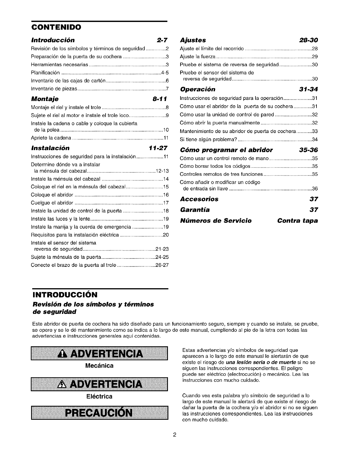
CONTENIDO
Introducci6n 2. 7
Revision de los sfmbolos y terminos de seguridad .............. 2
Preparaci6n de la puerta de su cochera .............................. 3
Herramientas necesarias ...................................................... 3
Planificaci6n ...................................................................... 4-5
Inventario de las cajas de cart6n .......................................... 6
Inventario de piezas .............................................................. 7
Montaje 8.11
Montaje el riel y instale el trole ............................................. 8
Sujete el riel al motor einstale el trole Ioco .......................... 9
Instale la cadena o cable y coloque la cubierta
de la polea ........................................................................ 10
Apriete la cadena ................................................................ 11
Instalaci6n 11.27
Instrucciones de seguridad para la instalaci6n ................... 11
Determine donde va a instalar
la mensula del cabezal ................................................ 12-13
Instale la mensula del cabezal ........................................... 14
Coloque el riel en la mensula del cabezal .......................... 15
Coloque el abridor .............................................................. 16
Cuelgue el abridor .............................................................. 17
Instale la unidad de control de la puerta ............................ 18
Instale las luces y la lente ................................................... 19
Instale la manija y la cuerda de emergencia ...................... 19
Requisitos para la instalaci6n electrica .............................. 20
Instale el sensor del sistema
reversa de seguridad ................................................... 21-23
Sujete la m_,nsula de la puerta ...................................... 24-25
Conecte el braze de la puerta al trole ........................... 26-27
Ajustes 28-30
Ajuste el Ifmitedel recorrido ...............................................28
Ajuste la fuerza ...................................................................29
Pruebe el sistema de reversa de seguridad .......................30
Pruebe el sensor del sistema de
reversa de seguridad ........................................................30
Operaci6n 31-34
Instrucciones de seguridad para la operaci6n ....................31
Como usar el abridor de la puerta de su cochera.............31
Como usar la unidad de control de pared ..........................32
Como abrir la puerta manualmente ....................................32
Mantenimiento de su abridor de puerta de cochera...........33
Si tiene algt]n problema? ....................................................34
C6mo programar el abridor 35.36
C6mo usar un control remoto de mano ..............................35
Como borrar todos los c6digos...........................................35
Controles remotos de tres funciones ..................................35
Como a_adir o modificar un codigo
de entrada sin Ilave ..........................................................36
Accesorios 37
Garantia 37
Nbmeros de Servicio Contra tapa
INTRODUCCION
Revisi6n de los simbolos y t_rminos
de seguridad
Este abridor de puerta de cochera ha sido diseSado para un funcionamiento seguro, siempre y cuando se instale, se pruebe,
se opere y se le de mantenimiento como se indica a Io largo de este manual, cumpliendo al pie de la letra con todas las
advertencias einstrucciones generales aquf contenidas.
Mec_nica
El_ctrica
Estas advertencias y/o sfmbolos de seguridad que
aparecen a Io largo de este manual le alertar_.n de que
existe el riesgo de una lesion seria o de muerte si no se
siguen las instrucciones correspondientes. El peligro
puede ser electrico (electrocucion) o mecanico. Lea las
instrucciones con mucho cuidado.
Cuando vea esta palabra y/o sfmbolo de seguridad a Io
largo de este manual le a]ertarA de que existe el riesgo de
daSar la puerta de la cochera y/o el abridor si no se siguen
las instrucciones correspondientes. Lea las instrucciones
con mucho cuidado.
2
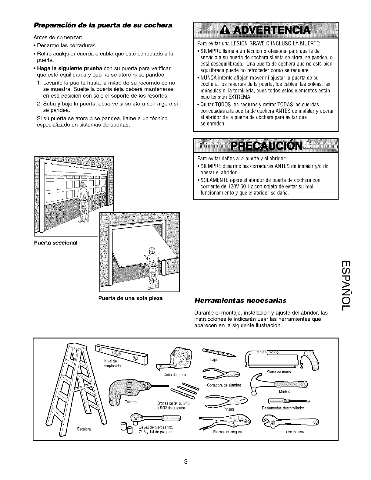
Preparaci6n de la puerta de su cochera
Antes de comenzar:
•Desarme las cerraduras.
• Retire cualquier cuerda o cable que este conectado a la
puerta.
• Haga la siguiente prueba con su puerta para verificar
que este equilibrada y que no se atore ni se pandee:
1. Levante la puerta hasta la mitad de su recorrido come
se muestra. Suelte la puerta esta deber_, mantenerse
en esa posici6n con solo el soporte de los resortes.
2. Suba y baD la puerta; observe si se atora con algo o si
se pandea.
Si su puerta se atora o se pandea, Ilame a un td,cnico
especializado en sistemas de puertas.
Paraevitar una LESIONGRAVE0 INCLUSOLA MUERTE:
• SIEMPREIlamea unt6cnicoprofesionalparaqueled_
servicioa su puertadecocherasi 6staseatora,sepandea,o
estddesequilibrada.Unapuertadecocheraquenoest6bien
equilibradapuedenoretrocedercomoserequiere.
• NUNCAintenteaflojar,moverni ajustarla puertadesu
cochera,los resortesde lapuerta,los cables,las poleas,las
m6nsulasni latornilleria,puestodosestoselementosestdn
bajotensi6nEXTREMA.
• QuitarTODOSlos segurosy retirarTODASlascuerdas
conectadasa la puertadecocheraANTESdeinstalary operar
el abridordelapuertadecocheraparaevitarque
se enreden.
Paraevitar dafios a la puerta y al abridor:
• SIEMPRE desarme las cerraduras ANTES de instalar y/o de
operar el abridor.
• SOLAMENTEopere el abridor de puerta de cochera con
corNente de 120V 60 Hzcon objeto de evitar su real
funcionamiento y que el abridor se dafie.
Puerta seccional
Puerta de una sola pieza Herramientas necesarias
Durante el montaje, instalaci6n y ajuste del abridor, las
instruccienes le indicaran usar las herramientas que
aparecen en la siguiente ilustraci6n.
m
o3
0
r-
Pinzas conseguro Llaveinglesa
3
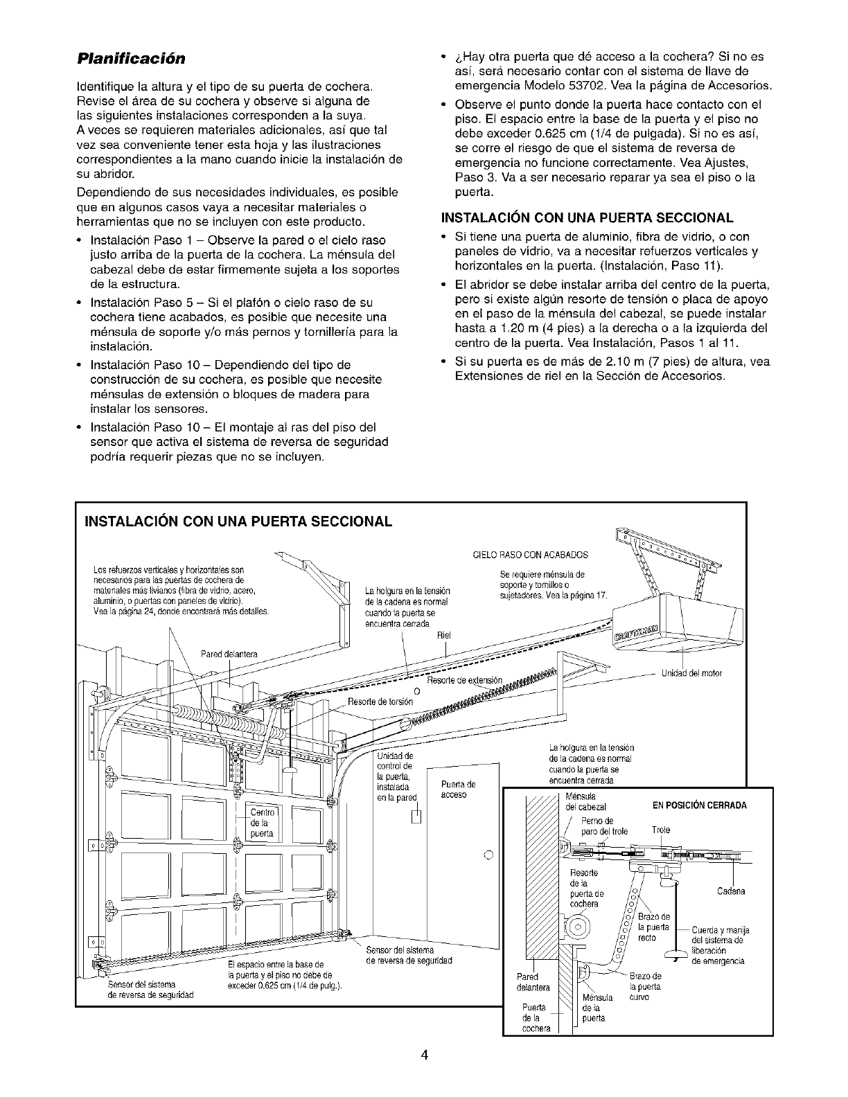
Planificaci6n
Identifique la altura y el tipo de su puerta de cochera.
Revise el Area de su cochera y observe si alguna de
las siguientes instalaciones corresponden a la suya.
A veces se requieren materiales adicionales, asi que tal
vez sea conveniente tener esta hoja y las ilustraciones
correspondientes a la mane cuando inicie la instalaci6n de
su abridor.
Dependiendo de sus necesidades individuales, es posible
queen algunos casos vaya a necesitar materiales o
herramientas que no se incluyen con este producto.
• Instalacion Paso 1 - Observe la pared o el cielo raso
justo arriba de la puerta de la cochera. La mensula del
cabezal debe de estar firmemente sujeta a los soportes
de la estructura.
• Instalaci6n Paso 5 - Si el plaf6n o cielo raso de su
cochera tiene acabados, es posible que necesite una
mOnsula de soporte y/o mAs pernos y tornillerfa para la
instalacion.
• Instalacion Paso 10 - Dependiendo del tipo de
construccion de su cochera, es posible que necesite
mOnsulas de extension o bloques de madera para
instalar los sensores.
• Instalacion Paso 10 - El montaje al ras del piso del
sensor que activa el sistema de reversa de seguridad
podria requerir piezas que no se incluyen.
&Hay otra puerta que de acceso a la cochera? Si no es
asi, sera necesario contar con el sistema de Ilave de
emergencia Modelo 53702. Vea la p_.gina de Accesorios.
Observe el punto donde la puerta hace contacto con el
piso. El espacio entre la base de la puerta y el piso no
debe exceder 0.625 cm (1/4 de pulgada). Si no es asi,
se corre el riesgo de que el sistema de reversa de
emergencia no funcione correctamente. Vea Ajustes,
Paso 3. Va a ser necesario reparar ya sea el piso o la
puerta.
INSTALACION CON UNA PUERTA SECCIONAL
• Si tiene una puerta de aluminio, fibra de vidrio, o con
paneles de vidrio, va a necesitar refuerzos verticales y
horizontales en la puerta. (InstalaciOn, Paso 11).
• El abridor se debe instalar arriba deI centre de la puerta,
pero si existe algL_nresorte de tension o placa de apoyo
en el paso de la mensula del cabezal, se puede instalar
hasta a 1.20 m (4 pies) a la derecha o a la izquierda del
centro de la puerta. Vea InstalaciOn, Pasos 1 a111.
• Si su puerta es de mas de 2.10 m (7 pies) de altura, vea
Extensiones de riel en la Seccion de Accesorios.
INSTALACION CON UNA PUERTA SECCIONAL
Los fefuerzosvedJcalesy horizontalesson
necesanospara laspuertas de cochera de
matenalesmas Iivianos(fibra de vidrio, aeero,
aluminio, opuertas con panebs de vidrio)
Vea ia pagina 24,donde eneontrar_m_s detailes
Pareddelantera
Laholgura enlatensiOn
de la cadenaes normal
cuandola puertase
encuenimcerrada
Riel
0
Resorb de torsion
ClELO RASO CONACABADOS
Se requiere mOnsulade
sopOdey tornillos o
suietadores.Yea la p_gina 17
Unidaddel motor
Jnidadde
controlde
la puefla,
instalada
en la par_
Sensor del sistema
de reversade seguridad
El espacioentre la base de
la puerta y eI piso no debe de
exceder0.625 crn (1/4de pulg.).
Sensor del sistema
de reversade seguridad
4
Puedade
acceso
©
Laholgumen latension
de]a cadenaes normal
cuandola pueda se
encuentracerrada
red
antera
ueda
ela
3chera
M_nsula
del cabezal EN POSICII_NCERRADA
Pernode
paro del Irole Trole
Resofle
de la
puerta de Cadena
cochera
Cuerda y manija
liberaciOn
de emergenda
Braz0de
la puerta
Mensuia curvo
de la
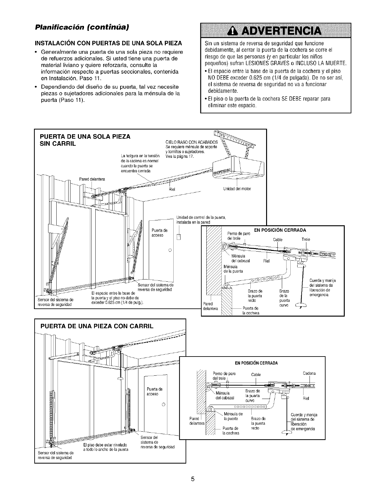
Planificacibn (continua)
INSTALACI()N CON PUERTAS DE UNA SOLA PIEZA
•Generalmente una puerta de una sola pieza no requiere
de refuerzos adicionales Si usted tiene una puerta de
material liviano y quiere reforzarla consulte la
informacion respecto a puertas seccionales, contenida
en Instalaci6n Paso 11
• Dependiendo del diseRo de su puerta, tal vez necesite
piezas o sujetadores adicionales para la mensula de la
puerta (Paso 11)
Sin un sistema de reversa de seguridad que funcione
debidamente, al cerrar la puerta de la cochera se corre el
riesgo de que las personas (yen particular los niSos
pequeSos) sufran LESIONESGRAVESo INCLUSOLA MUERTE.
• El espacio entre la basede la puerta de la cochera y el piso
NO DEBEexceder 0.625 cm (1/4 de pulgada). De no ser asi,
el sistema de reversa de seguridad no va a funcionar
debidamente.
• Elpiso o la puertadelacocheraSEDEBErepararpara
eliminaresteespacio
PUERTA DE UNA SOLA PIEZA
SIN CARRIL
La bolgura enla tensi6n
de la cederla es normal
cuando la puerta $e
e_oueritra ¢erreda
Pareddelantera
ClELO RASOCON ACABADOS
Serequiere m_nsulade soporte
y tomillos osujetedores
Yea la pagina 17
Riel Unidad del motor
Sensor del sistema de
reversade segeddad
Sensor del sistemade
reversa de segeddad
Elespacio entre la bate de
la puerta y el piso no debe de
exceder0625 cm (1/4 de pulg)
Unidad de contro]de ]a puerta,
instaledaen lapared
Pemo de paro
[red
lantera
EN POSIClON CERRADA
Tro4e
Cuerday manija
de1sistema de
liberaci6nde
emergencia
PUERTA DE UNA PIEZA CON CARRIL
EN POSICIONCERRADA
Pernode paro Cable Oadena
Sensor del sistema de
reversa de segeddad
El piso debeestar nivelado
a todo Io anchode la pueda
Puedade
aooeso
(
Sensordel
sistemade
reversa de segufided
Pared l
delanteral
la oochera
Brazode
la pueda
recto
Riel
Cuerday manija
del sistemade
_eraci6n
5
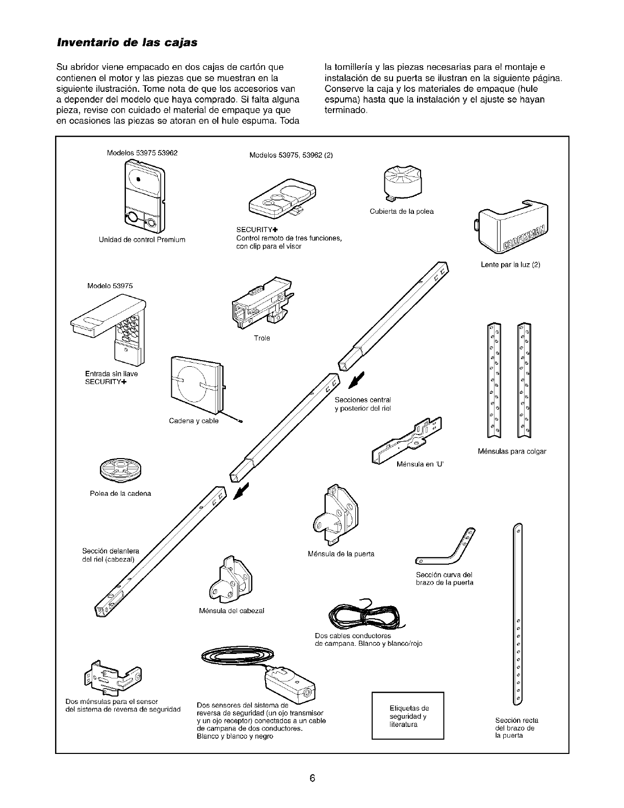
Inventario de las cajas
Su abridor viene empacado en dos cajas de cart6n que
contienen el motor y las piezas que se muestran en la
siguiente ilustracion. Tome nora de que los accesorios van
a depender del modelo que haya comprado. Si falta alguna
pieza, revise con cuidado el material de empaque ya que
en ocasiones las piezas se atoran en el hule espuma. Toda
la tornilleria y las piezas necesarias para el montaje e
instalaci6n de su puerta se ilustran en la siguiente p_.gina.
Conserve la caja y los materiales de empaque (hule
espuma) hasta que la instalaci6n y el ajuste se hayan
terminado.
Medetos 53975 53962
Unidad de conlrel Premium
Modelos 53975, 53962 (2)
SECURITY÷
Control remoto de tres funciones,
con clip para el visor
Cubietta de la polea
Modelo 53975
Enlrada sin Itave
SECURITY+
@
Polea de la cadena
Trole
Y
Secciones central
y posterior del riel
Lente par la luz (2)
M#nsulas para colgar
Secci6n delantera
del riel (cabezal)
Dos m_nsulas para el sensor
del sistema de reversa de seguridad
M_nsula de la puerta
SeccJ6n curva del
brazo de la puetta
M_nsula del cabezal
reversa de seguridad (un ojo transmisor
y un ojo receptor) conectados a un cable
de campana de dos conductores.
Blanco y blanco y negro
Dos Gables conduclores
de campana. Blanco y blanco/rejo
Eliquetas de
seguridad y
literatura Secci6n recla
del brazo de
la puerla
6
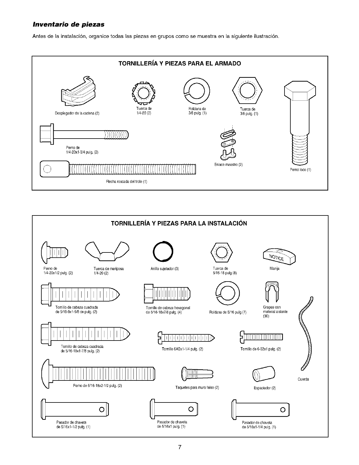
Inventario de piezas
Antes de la instalaci6n, organice todas las piezas en grupos como se muestra en la siguiente ilustraci6n.
TORNILLER|A Y PIEZAS PARA EL ARMADO
© ©©
Tuerca de Roldanade Tuerca de
Despiegadorde la cadena (2) 1/4-20 (2) 3/8pulg (1) 3/8 pulg (1)
dPemo de
1/4-20xl-3/4 pulg. (2)
Enlacemaestro(3)
Flecharoscadadel trole (1)
TORNILLERiA Y PIEZAS PARA LA INSTALACION
PemoIoco (1)
Perno de Tuerca de mariposa Anillo sujetador(3)
1/4-20xl/2 pulg (2) 1/4-20(2)
de 5/16-9xl-5/8 de pulg (3)
Tomillo de cabezacuadrada
de 5/16-18xl-7/8 pulg. (2)
Pemo de 5/16-18x2-1/2pulg. (2)
Tornillode cabezahexagonal
de 5/16-18x7/8pulg {4)
Torniilo 6ABxlq/4 pulg. (2)
Taquetes para inure falso {2)
©
Tuercade
5/16-18pulg (8)
©
Roldanade 5/16 pulg(7)
Manija
Grapascon
materialNslante
Tornillo de 6-32xl pulg (2)
Espaciador(2)
ol C C
Pasadorde chaveta Pasadorde chaveta Pasadorde chaveta
de 5/16xlq/2 pulg. (1) de 5/16xl pulg. (1) de 5/16x1-1/4pulg (1)
l
Cuerda
7
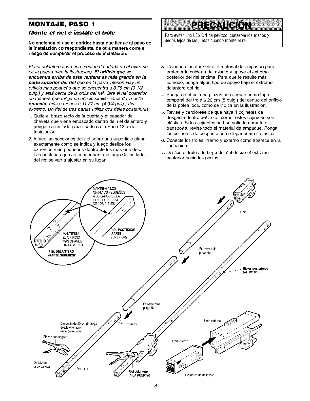
MONTAJE, PASO 1
Monte el riel e instale el trole
No encienda ni use el abridor hasta que Ilegue al paso de
la instalacibn correspondiente, de otra manera corre el
riesgo de complicar el proceso de instalacibn.
Paraevitar una LESI6N de pellizco, conserve los manos y
dedos lejos de las juntas cuando monte el reil.
El fie! delantero tiene una "ventana" cortada en e! extremo 3.
de la puerta (vea la ilustraci6n). El orifieio que se
encuentra arriba de esta ventana es m_s grande en la
parte superior del riel queen la parte inferiol: Hay un
orificio mas peque#o que se encuentra a 8.75 cm (3-1/2
pulg.) y esta cerca de la ori!la del rieL Gire el riel posterior 4.
de manera que tenga un orificio similar cerca de la ori!la
opueste, mas o menos a 11.87cm (4-3/4 pulg.) de/
extremo. Un rie! de tres partes utiliza dos deles posteriores 5.
1. Quite el brazo recto de la puerta y el pasador de
chaveta que viene empacado dentro del riel delantero y
p6ngalo a un lado para usarlo en la Paso 12 de la
Instalaci6n.
2. Affnee las secciones del riel sobre una superficie plana 6.
exactamente come se indica y luego deslice los
extremos m_.s pequeffos dentro de los mas grandes. 7.
Las pestaffas que se encuentran a Io largo de los lados
del riel se van a ajustar en su lugar.
Coloque el motor sobre el material de empaque para
proteger la cubierta del mismo y apoye el extreme
posterior del riel encima. Para que le resulte m_.s
c6modo, ponga algdm tipo de apoyo bajo el extreme
delantero del rieL
Ponga on el riel una pinzas con seguro come tope
temporal del trole a 20 cm (8 pulg.) del centro del orificio
do la polea Ioca, come so indica en la ilustraci6n.
Revise y cerci6rese de que haya 4 cojinetes de
desgaste dentro del trole interno, estos cojinetes son
pl_.stico. Si los cojinetes se han soltado durante el
transporte, revise todo el material de empaque. Ponga
los cojinetes de desgaste en su lugar como se indica.
Conecte los troles interno y externo como aparece on la
ilustraci6n.
Deslice el trole a Io largo del riel desde el extreme
posterior hacia las pinzas.
Extremom_s
de la p01eai0ca
_' eOa_'___ T ro,e i[Itefrlo
Orificiode _
la poleaIoca Ventana Riel delantero
(A LA PUERTA)
Rielesposteriores
(AL MOTOR)
Cojinetesde desgaste
Trole externo
8
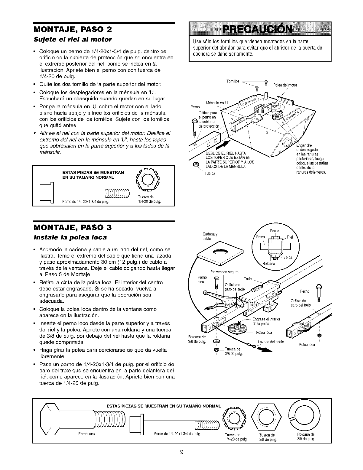
MONTAJE, PASO 2
Sujete el riel al motor
•Coloque un perno de 1/4-20xl-3/4 de pulg. dentro del
orificio de la cubierta de protecci6n que se encuentra en
el extremo posterior del r/el, como se indica en la
ilustraci6n. Apt/ere bien el pemo con con tuerca de
1/4-20 de pulg.
• Quite los dos tornillo de la parte superior del motor.
• Coloque los desplegadores en la md,nsula en 'U'.
Escuchara un chasquido cuando quedan en su lugar.
• Ponga la md,nsula en 'U' sobre el motor con el lado
piano hacia abajo y alfnee los orificios de la m6nsula
con los orificios de los tornillos. Sujete con los tomillos
que quit5 antes.
•A!fnee e! r/e! con la parte superior del motor. Deslice el
extremo de! r/e! en la mensula en 'U', hasta los topes
que sobresalen en la parte superior y a los lados de la
mensula.
ESTAS PIEZAS SE MUESTRAN ._/ . _'%
EN SU TAMAblO NORMAL
[_ Tuerca de
Pemode 1/4-20xl-3/4de pulg 1/4-20de pulg
Use s61olos tornillos que vienen montados en la parte
superior del abridor para evitar que el abridor de la puerta de
cochera se daSeseriamente.
Tomillos _ Poleadel motor
/
Mensulaen 'U'
Pemo _ _
Orificio para _
elpernoen
la cubierta
de protecci6n _ _
JDESLICEEL RIEL HASTA en las ranuras
f DOESSvCPEE'L0 S TCPEEELguEELEHs_A EN _ postedores ,uo, eg
LADOSDE LAMSNSULA den_o de lap
i_ LAPARTESUPERIORYALOS c010 uelas estaSas
i Tuerca ranurasdelanteras.
MONTAJE, PASO 3
Instale la polea Ioca
• Acomode la cadena y cable a un lado del r/el, como se
ilustra. Tome el extremo del cable que tiene una lazada
y pase aproximadamente 30 cm (12 pulg.) de cable a
traves de la ventana. Deje el cable colgando hasta Ilegar
al Paso 5 de Montaje.
• Retire la cinta de la polea Ioca. El interior del centro
debe estar engrasado. Si se ha secado, vuelva a
engrasarlo para asegurar que la operaci6n sea
adecuada.
• Coloque la polea Ioca dentro de la ventana como
aparece en la ilustraci6n.
• Inserteelpernolocodesdelapartesuperioryatrav6s
del r/el y la polea. Apriete con una roldana y una tuerca
de 3/8 de pulg. por debajo del r/el hasta que la roldana
quede comprimida.
• Haga girar la polea para cerciorarse de que da vuelta
libremente.
• Pase un perno de 1/4-20xl-3/4 de pulg. por el orificio de
paro del trole que se encuentra en la parte delantera del
r/el, como aparece en la ilustraci6n. Apriete bien con una
tuerca de 1/4-20 de pulg.
"_ _iCadenay Polea
/P=ooosoo ,o-'---I/
Pernc_ T o e
Ioco Onficiode
Roldanade _ _ _
3/8de pulg _ _azada del cable
I_ Tueroade_--'_llh.
Po]eaIoca
i 3/8de pulg.
ESTAS PIEZAS SE MUESTRAN EN SLI TAMAIqO NORMAL
Pemo Ioc0 _ Perno de 1/4-20xl-3/4 de pulg Tuerca de
1/4-20de pulg.
Tuerca de
3/8de pulg
Roldanade
3/8 de pulg.
9
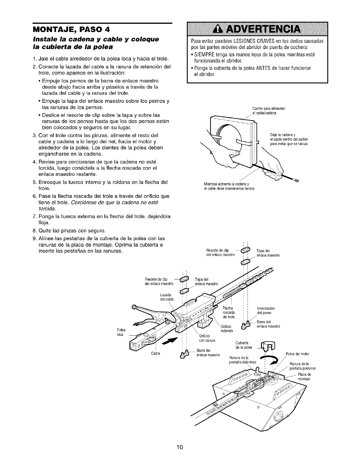
MONTAJE, PASO 4
Instale la cadena y cable y coloque
la cubierta de la polea
1 Jale el cable alrededor de la polea Ioca y hacia el trole
2 Conecte la lazada del cable a la ranura de retenci6n del
trole, come aparece en la ilustraci6n:
•Empuje los pernos de la barra de enlace maestro
desde abajo hacia arriba y p_selos a traves de la
lazada del cable y la ranura del trole
• Empuje la tapa del enlace maestro sobre los pernos y
las ranuras de los pernos
• Deslice el resorte de clip sobre la tapa y sobre las
ranuras de los pemos hasta que los dos pernos est_,n
bien colocados y seguros en su lugar
3 Con el trole contra las pinzas, alimente el resto del
cable y cadena a Io largo del riel, hacia el motor y
alrededor de la polea Los dientes de la polea deben
engancharse en la cadena
4 Revise para cerciorarse de que la cadena no este
torcida, luego con6ctela a la flecha roscada con el
enlace maestro restante
5 Enrosque la tuerca interna y la roldana en la flecha del
trole
Paraevitar posibles LESIONESGRAVESen los dedos causadas
per las partes m6viles del abridor de puerta de cochera:
• SIEMPREtenga las manes lejos de la polea mientras est6
funcionando el abridor.
• Ponga la cubierta de la polea ANTESde hacer funcionar
el abridor.
Carton para alimentar
el cabWcadena
Dejela cadena y
el cabledentro del cafl6n
para evitarque se tuerza
Mientms alimente la cadena y
el cable debemantenefl0stenses
6. Pase la flecha roscada del trole a traves del ofificio que
tiene el trole. Cerci6rese de que la cadena no est#
torcida
7 Ponga la tuerca externa en la flecha del trole, dejandola
floja
8 Quite las pinzas con seguro
9 Alinee las pestafias de la cubierta de la polea con las
ranuras de la placa de montaje Oprima la cubierta e
inserte las pestafias en las ranuras
Polea
Ioca
i
Resorte de clip _ Tapadel
del enlace maestro_ enlacemaestro
i i
i i i
i i i i
Resode de dip _ Tapa del
del enlace maestro enlace maestro
i I
Lazada
del cane : : .-:
i • i
Flecha : : Indentaci6n
r0scada ' : de gem0
I i
del trole : ,
,Barra del
sire
red0nd0
: , Ofifieio
_nura redondoCubJ_rta
, : con[anu[a
,de la polea
_ '
Cable enlacemaestro Ranurade la '
pesta_adelantera :
Poleadel motor
/
Ranurade la
f pestaSaposterior
Placa de
montaie
lO
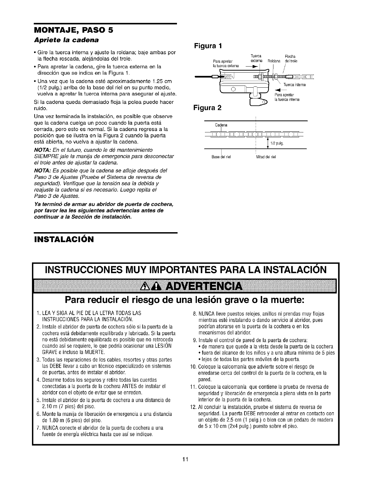
MONTAJE, PASO 5
Apriete la cadena
•Gire la tuerca interna y ajuste la roldana; baje ambas por
la flecha roscada, alejandolas del trole.
• Para apretar la cadena, gire la tuerca extema en la
direcci6n que se indica en la Figura 1.
• Una vez que la cadena est6 aproximadamente 1.25 cm
(1/2 pulg.) arriba de la base del riel en su punto medio,
vuelva a apretar la tuerca interna para asegurar el ajuste.
Si la cadena queda demasiado floja la polea puede hacer
ruido.
Una vez terminada la instalaci6n, es posible que observe
que la cadena cuelga un poco cuando la puerta esta
cerrada, pero esto es normal. Si la cadena regresa a la
posici6n que se ilustra en la Figura 2 cuando la puerta
esta abierta, no vuelva a ajustar la cadena.
NOTA: En el futuro, cuando le de mantenimiento
SIEMPRE jale la manija de emergencia para desconectar
el trole antes de ajustar la cadena.
NOTA: Es posible que la cadena se af!oje despues del
Paso 3 de Ajustes (Pruebe e! Sistema de reversa de
seguridad). Verifique que la tensi6n sea la debida y
reajuste la cadena si es necesario. Luego repita el
Paso 3 de Ajustes.
Ya terrain6 de armar su abridor de puerta de cochera,
por favor lea les siguientes advertencias antes de
continuar a la Secci6n de instalaci6n.
Figura 1
Paraapretar
Tuerca Flecha
extema Roldana deJtro]e
Figura 2
l
Cadena
Basede1riel Mitadde1riel
INSTALACION
INSTRUCCIONES MUY IMPORTANTES PARA LA INSTALACION
Para reducir el riesgo de una lesibn grave o la muerte:
1. LEAYSIGAAL PIEDELALETRATODASLAS
INSTRUCCIONESPARALA INSTALACION.
2. Instaleel abridordepuertadecocheras61osi la puertadela
cocheraest_debidamenteequilibraday lubricada.Si lapuerta
noest_debidamenteequilibradaes posiblequeno retroceda
cuandoasi serequiere,Io quepodrfaocasionarunaLESION
GRAVEe inclusolaMUERTE
3. Todas las reparacionesde los cables, resortes y otras partes
las DEBEIlevar a cabo un t_cnico especializadoen sistemas
de puertas,antes de instalar el abridor.
4. Desarmetodos los seguros y retire todas las cuerdas
conectadas a la puerta de la cochera ANTESde instalar el
abridor con el objeto de evitar que se enreden.
5. Instale el abridor de la puerta de cochera a una distancia de
2.10 m (7 pies) del piso.
6. Monte la manija de liberaci6n de emergencia a una distancia
de 1.80 m (6 pies) del piso.
7. NUNCAconecteel abridor de la puerta de cochera a una
fuente de energia el_ctrica hasta que as[ se indique.
8. NUNCAIlevepuestos relojes, anillos ni prendas muy flojas
mientras est_ instalando o dando servicio al abridor, pues
podrian atorarse en la puerta de la cochera o en los
mecanismos del abridor.
9. Instale el control de pared de la puerta decochera:
• de manera que quede a la vista desde la puerta de la cochera
• fuera del alcance de los niSosy a una altura minima de 5 pies
• lejos de todas las partes m6viles de la puerta.
10. Coloque la calcomania que advierte sobre el riesgo de
enredarse cerca del control de la puerta de la cochera, en la
pared.
11. Coloque la calcomania que contiene la pruebade reversa de
seguridad y liberaci6n de emergencia a plena vista en la parte
interior de la puerta de la cochera.
12. AI concluir la instalaci6n, pruebe el sistema de reversa de
seguridad. La puerta DEBEretroceder al entrar encontacto con
un objeto de 2.5 cm (1 pulg.) o bien con un pedazode madera
de 5 x 10 cm (2x4 pulg.) puesto sobre el piso.
11
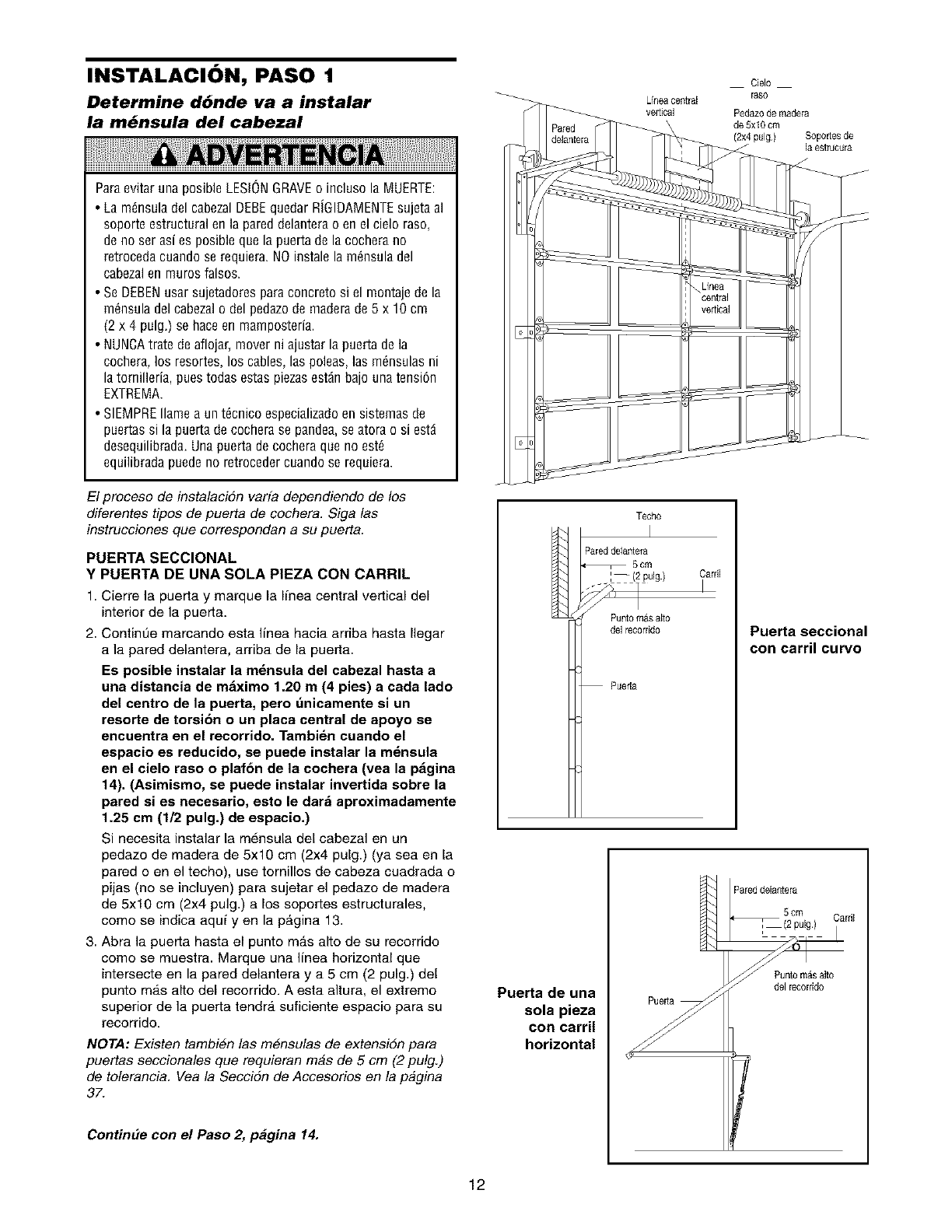
INSTALACION, PASO 1
Determine d6nde va a instalar
la m_nsula del cabezal
Paraevitar una posible LESIONGRAVEo incluso la MUERTE:
• La m_nsula del cabezalDEBEquedar RiGIDAMENTEsujeta al
soporte estructural en la pared delantera o en el cielo raso,
de no ser asi es posible que la puerta de la cochera no
retroceda cuando se requiera. NO instale la mdnsula del
cabezal en muros falsos.
• Se DEBENusar sujetadores para concreto si el montaje de la
mdnsula del cabeza]o del pedazode maderade 5 x 10 cm
(2 x 4 pulg.) se hace en mamposteria.
• NUNCAtrate deaflojar, mover ni ajustar la puerta de la
cochera, los resortes, los cables, las poleas, las mdnsulas ni
la tornilleria, pues todas estas piezasest_n bajo una tensidn
EXTREMA.
• SIEMPRE Ilame a un tdcnico especializadoen sistemas de
puertas si la puerta de cochera se pandea, se atora o si estd
desequilibrada. Una puerta de cochera que no est_
equilibrada puede no retroceder cuando se requiera.
El proceso de instalacidn varia dependiendo de los
diferentes tipos de puerta de cochera. Siga las
instrucciones clue correspondan a su puerta.
PUERTA SECCIONAL
Y PUERTA DE UNA SOLA PIEZA CON CARRIL
1. Cierre la puerta y marque la Iinea central vertical del
interior de la puerta.
2. ContinUe marcando esta linea hacia arriba hasta Ilegar
a la pared delantera, arriba de la puerta.
Es posible instalar la m_nsula del cabezal hasta a
una distancia de m_ximo 1.20 m (4 pies) a cada lado
del centro de la puerta, pero dnicamente si un
resorte de torsi6n o an placa central de apoyo se
encuentra en el recorrido. Tambidn cuando el
espacio es reducido, se puede instalar la mdnsula
en el cielo raso o plaf6n de la cochera (vea la p_gina
14). (Asimismo, se puede instalar invertida sobre la
pared si es necesario, esto le dar_ aproximadamente
1.25 cm (1/2 pulg.) de espacio.)
Si necesita instalar la mensula del cabezal en un
pedazo de madera de 5x10 cm (2x4 pulg.) (ya sea en la
pared o en el techo), use tornillos de cabeza cuadrada o
pijas (no se incluyen) para sujetar el pedazo de madera
de 5x10 cm (2x4 pulg.) a los soportes estructurales,
como se indica aqui yen la p_gina 13.
3. Abra la puerta hasta el punto m_.s alto de su recorrido
como se muestra. Marque una linea horizontal que
intersecte en la pared delantera y a 5 cm (2 pulg.) del
punto ma.s alto del recorrido. A esta altura, el extremo
superior de la puerta tendra, suficiente espacio para su
recorrido.
NOTA: Existen tambien las m#nsulas de extensidn para
puertas seccionales que requieran mas de 5 cm (2 pulg.)
de tolerancia. Vea la Seccidn de Accesorios en la pagina
37.
ContinEle con el Paso 2, p_gina 14.
Cielo
Lfneacentral raso
vertical Pedaz0de madera
de 5xl 0 cm
(2x4 pulg) Soportesde
la estrucura
Techo
I
Pared delantera
5cm
[--/2 pulg.) Cardl
i
Punto m_s alto
del recorddo
Puerta
Puerta seccional
con carril curvo
Puerta de una
sola pieza
con carril
horizontal
Pared delanter__
_2C_ul Cardl
12
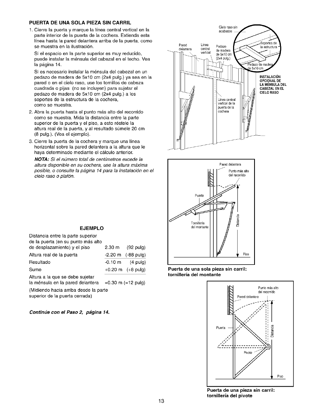
PUERTA DE UNA SOLA PIEZA SIN CARRIL
1. Cierre la puerta y marque la ffnea central vertical en la
parte interior de la puerta de la cechera. Extienda esta
ffnea basra la pared delantera arriba de la puerta, como
se muestra en la ilustraci6n.
Si el espacio en la parte superior es muy reducido,
puede instalar la mensula del cabezal en el techo. Yea
la p_.gina 14.
Si es necesarie instalar la m6nsula del cabezal en un
pedazo de madera de 5x10 cm (2x4 pulg.) ya sea en la
pared e en el cielo rase, use los temillos de cabeza
cuadrada o pijas (no se incluyen) para sujetar el
pedazo de madera de 5x10 cm (2x4 pulg.) a los
sepertes de la estructura de la cochera,
come se muestra.
2. Abra la puerta hasta el punto m_.s alto del recorrido
como se muestra. Mida la distancia entre la parte
superior de la puerta y el piso, a esto restele la
altura real de la puerta, y al resultado semele 20 cm
(8 pulg.). (Vea el ejemplo).
3. Cierre la puerta de la cochera y marque una linea
horizontal sobre la pared delantera a la altura que le
haya determinado mediante el c_lculo anterior.
NOTA: Si e! n#mero total de centfmetros excede la
altura disponible en su cochera, use la altura mbxima
posible, o consulte la pagina 14 para la Instalacidn en e!
cielo raso o plafon.
EJEMPLO
Distancia entre la parte superior
de la puerta (en su punto m_.s alto
de desplazamiento) y el piso
Altura real de la puerta
Resultado
Sume
AItura a la que se debe sujetar
la m_,nsula en la pared delantera =0.30 m (=12 pulg)
(Midiendo hacia arriba desde la parte
superior de la puerta cerrada)
2.30 m (92 pulg)
-2.20 m (-88 pulg)
-0.10 m (4 pulg)
+0.20 m (+8 pulg)
ContinEle con el Paso 2, p_gina 14.
Pared Linea Pedazo
delantera central de madefa
vertical de 5x10 cm
(2x4 pulg.)
Pareddelantera
/Punto masalto
de1recorrido
/
S_ _ Piso
Puerta de una sola pieza sin carrih
tornillerfa del montante
Puerta
INSTALACI()N
OPCIONAL DE
LA MENSULADEL
CABEZALEN EL
CIELORASO
Punto masalto
de1recorddo
PareddeJantera _ .
" ......";;'; t
... ,:::,,
Puerta de una pieza sin carrih
tornilleria del pivote
13
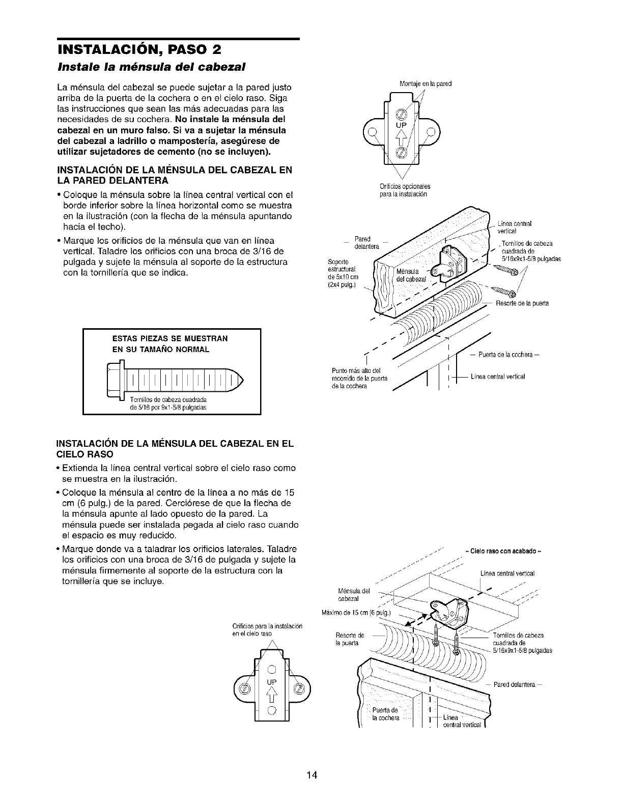
INSTALACION, PASO 2
Instale la m_nsula del cabezal
La mensula del cabezal se puede sujetar a la pared justo
arriba de la puerta de la cochera o en el cielo raso. Siga
las instrucciones que sean las mAs adecuadas para las
necesidades de su cochera. No instale la m_nsula del
cabezal en un muro falso. Siva a sujetar la m_naula
del cabezal a ladrUlo o mamposteria, aaegr_reae de
utilizar sujetadores de cemento (no ae incluyen).
INSTALACI(_N DE LA MENSULA DEL CABEZAL EN
LA PARED DELANTERA
•Coloque la mensula sobre la linea central vertical con el
borde inferior sobre la linea horizontal come se muestra
en la ilustraci6n (con la fiecha de la mensula apuntando
hacia el techo).
• Marque los orificios de la m6nsula que van en Ifnea
vertical. Taladre los orificios con una broca de 3/16 de
pulgada y sujete la mensula al soporte de la estructura
con la tomilleda que se indica.
ESTAS PIEZAS SE MUESTRAN
EN SU TAMANO NORMAL
de 5/16 por 9xl-5/8 pulgedas
Montajeen la pared
Pared
delantera
Orificiosopcionales
para la instalaci6n
Soporte
estructural
de 5x10 cm
(2x4pulg.)
/
/
/
Puntom&salto del
recorridode la puerta
de la cochera
Lhea central
vertical
,Tornillos de cabeza
cuadrada de
5/16x9xl-5/Spulgadas
Resortede la pueda
f
Puertade la oochera
INSTALACI()N DE LA MI_NSULA DEL CABEZAL EN EL
CIELO RASO
• Extienda la linea central vertical sobre el cielo raso como
se muestra en la ilustraci6n.
• Coloque la mensula al centre de la linea a no m_.s de 15
cm (6 pulg.) de la pared. Cerci6rese de que la flecha de
la mensula apunte al lado opuesto de la pared. La
mensula puede ser instalada pegada al cielo raso cuando
el espacio es muy reducido.
• Marque donde va a taladrar los orificios laterales. Taladre
los orificios con una broca de 3/16 de pulgada y sujete la
mensula firmemente al soporte de la estructura con la
tornillerfa que se incluye.
Orificiospara ]ainstalaci6n
en el cieloraso
o
M_nsulade]
cabezal
M_ximode 15 cm (6 pulg)
Resole de
la pueda cuadrada de
pulgadas
Pared delantera
Puedade
lac0chera cent_alve_ical
14
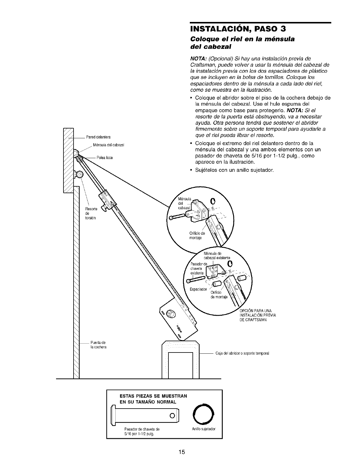
M_nsuladel cabezaJ
J
INSTALACION, PASO 3
Coloque el riel en la m_nsula
del cabezal
NOTA: (Opciona!) Si hay una instalaci6n previa de
Craftsman, puede volver a usar la m_nsula de! cabezal de
la instalaci6n previa con los dos espaciadores de plastico
que se ineluyen en la bolsa de tomil!os Coloque los
espaciadores dentro de la m_nsula a cada lade del riel,
come se muestra en la ilustraci6n
• Coloque el abridor sobre el piso de la cochera debajo de
la mensula del cabezal Use el hule espuma del
empaque como base para protegerlo NOTA: Si el
resorte de la puerta esta obstruyendo, va a necesitar
ayuda Otra persona tendra que sostener e! abridor
firmemente sobre un soporte temporal para ayudarle a
que e! rie! pueda librar el resorte
• Coloque el extremo del riel delantero dentro de la
mensula del cabezal y una ambos elementos con un
pasador de chaveta de 5/16 por 1-1/2 pulg, como
aparece en la ilustraci6n
• Sujetelos con un anillo sujetador
de
t0rsi6n
/
Orificiode
montaje
0
cabezaJexistenle
0
Espaciador Odfido
de monroe
INSTALACIONPREVIA
DE CRAFTSMAN
lacochera
Caiade1abridor o soportetemporal
ESTAS PIEZAS SE MUESTRAN
EN SU TAMANONORMAL 0
Pasadorde chaveta de Anillo sujetador
5/16 pot 1-1/2pulg.
15
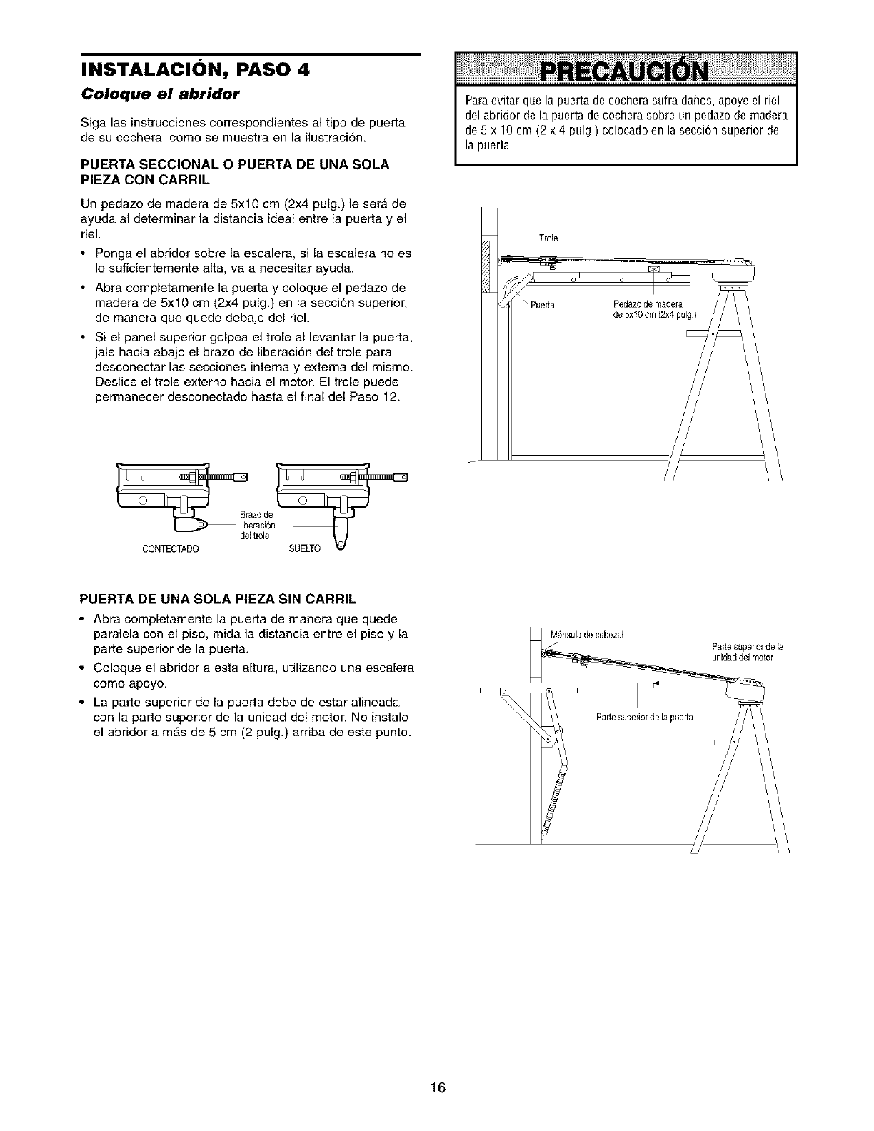
INSTALACION, PASO 4
Coloque el abridor
Siga las instrucciones correspondientes al tipo de puerta
de su cochera, como se muestra en la ilustracion
PUERTA SECCIONAL OPUERTA DE UNA SOLA
PIEZA CON CARRIL
Un pedazo de madera de 5x10 cm (2x4 pulg) le ser_ de
ayuda al determinar la distancia ideal entre la puerta y el
riel
•Ponga el abridor sobre la escalera, si la escalera no es
Io suficientemente alta, va a necesitar ayuda
• Abra completamente la puerta y coloque el pedazo de
madera de 5x10 cm (2x4 pulg) en la secci6n superior,
de manera que quede debajo del deL
• Si el panel superior golpea el trole al levantar la puerta,
jale hacia abajo el brazo de liberaci6n del trole para
desconectar las secciones interna y externa del mismo
Deslice el trole externo hacia el motor El trole puede
permanecer desconectado hasta el final del Paso 12
Paraevitar que la puerta decochera sufra da5os,apoye el riel
del abridor de la puerta decochera sobre un pedazode madera
de 5 x 10 cm (2 x 4 pulg.) colocado en la secci6n superior de
la puerta.
delt_le
CONTECTADO
PUERTA DE UNA SOLA PIEZA SIN CARRIL
• Abra completamente la puerta de manera que quede
paralela con el piso, mida la distancia entre el piso y la
parte superior de la puerta.
• Coloque el abridor a esta altura, utilizando una escalera
como apoyo.
• La parte superior de la puerta debe de estar alineada
con la parte superior de la unidad del motor. No instale
el abridor a mAs de 5 cm (2 pulg.) arriba de este punto.
Mensulade cabezul
I
Pade superiorde la puerta
Pade superiorde la
unidaddel motor
16
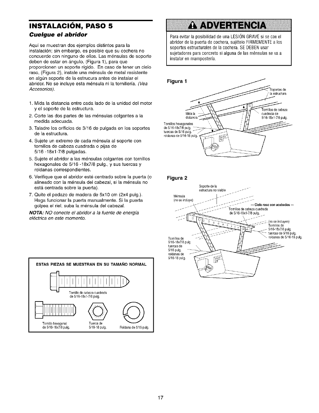
INSTALACION, PASO 5
Cuelgue el abridor
Aqui se muestran dos ejemplos distintos para la
instalaci6n; sin embargo, es posible que su cochera no
concuerde con ninguno de ellos. Las mensulas de soporte
deben de estar en angulo, (Figura 1), para que
prepercionen un soperte rigido. En case de tenet un cielo
raso, (Figura 2), instale una mensula de metal resistente
en algL_nsoporte de la estrucura antes de instalar el
abridor. No se incluye esta m6nsula ni la ternilleffa. (Vea
Accesorios).
1. Mida la distancia entre cada lado de la unidad del motor
y el seperte de la estructura.
2. Corte las dos partes de las m6nsulas celgantes a la
medida adecuada.
3. Taladre los erificios de 3/16 de pulgada en los seportes
de la estructura.
4. Sujete un extreme de cada m6nsula al soperte con
tornilles de cabeza cuadrada o pijas de
5/16 - 18xl -7/8 pulgadas.
5. Sujete el abridor a las m6nsulas colgantes con tornillos
hexagonales de 5/16 -18x7/8 pulg., y sus tuercas y
reldanas correspondientes.
6. Verifique que el abridor est6 centrado sobre la puerta (e
alineade con la m6nsula del cabezal, si la mensula no
esta centrada sobre la puerta).
7. Quite el pedaze de madera de 5x10 cm (2x4 pulg.).
Haga funcionar la puerta manualmente. Si la puerta
golpea el riel, suba la mensula del cabezal.
NOTA: NO conecte e! abridor a la fuente de energia
electrica en este momento.
ESTAS PIEZAS SE MUESTRAN EN SU TAMANO NORMAL
Tornillode cabezacuadrada
de 5/16-18xl-7/8 pulg
©©
T0millohexagonal Tuerca de
de 5/16-18x7/8pulg. 5/16-18pulg. R01danade 5/16 pulg
Paraevitar la posibilidad de una LESIONGRAVEsi se cae el
abridor de la puerta de cochera, suj6telo FIRMEMENTEa los
soportes estructurales de la cochera. SE DEBENusar
sujetadores para concreto si alguna de las m6nsulas se va a
instalar en mamposteria.
Figura 1
/la estructura
Mida la
T0rnill0s hexag0nales
tuercas de 5/16
roldanasde 5/16-18pulg. ,
T0rnill0sde cabeza
cuadrada de
5116-18x1-7/Spuig
Figura 2
Tornillosde _--%"
5/16-18x7/8pulg
l_ercasde \
5/16 pulg.
roldanasde
(no se induyen)
Tornillosde
5/16-18x7/8pulg
i pulg.
• roldanasde 5/16-18puig.
5/16-18pulg.
17
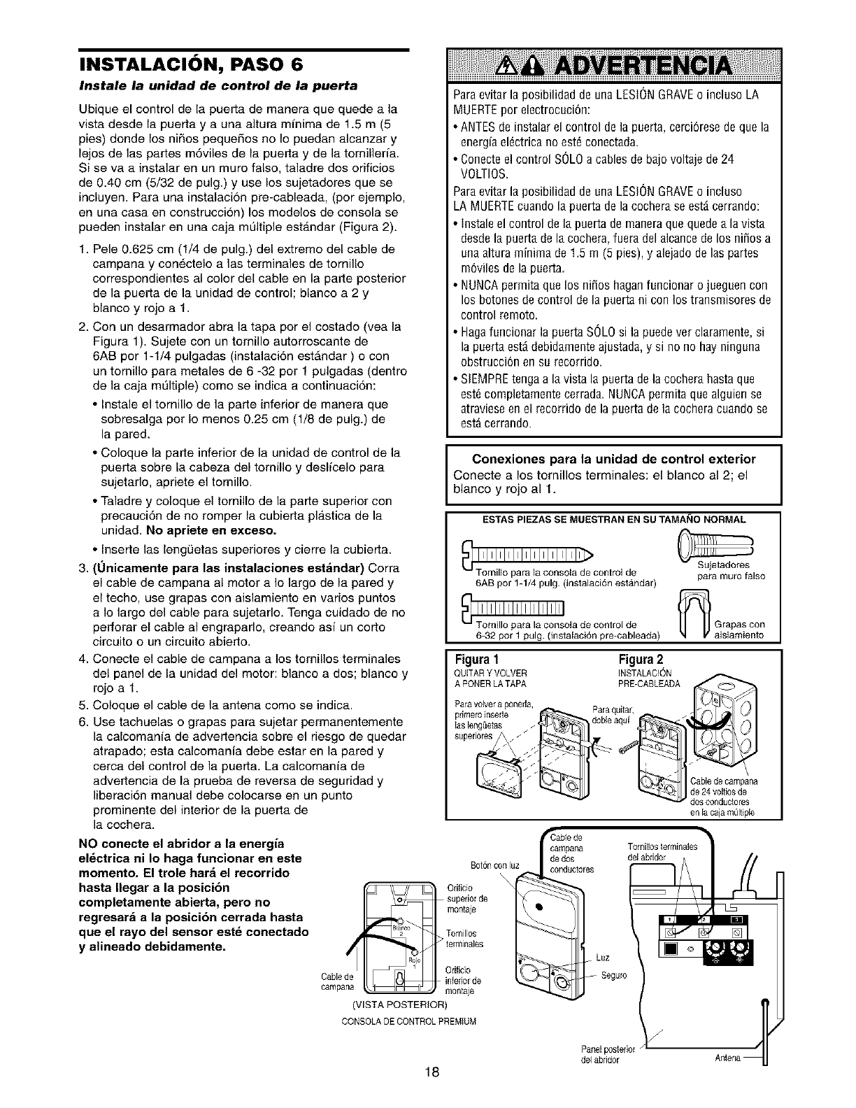
INSTALACION, PASO 6
Instale la unidad de control de la puerta
Ubique el control de la puerta de manera que quede a la
vista desde la puerta y a una altura mfnima de 1.5 m (5
pies) donde los niRos pequeSos no Io puedan alcanzar y
lejos de las partes m6viles de la puerta y de la tornilleria.
Si se va a instalar en un muro falso, taladre dos orificios
de 0.40 cm (5/32 de pulg.) y use los sujetadores que se
incluyen. Para una instalaci6n pre-cableada, (por ejemplo,
en una casa en construccion) los modelos de consola se
pueden instalar en una caja mt_ltiple est_.ndar (Figura 2).
1. Pele 0.625 cm (1/4 de pulg.) del extremo del cable de
campana y conOctelo alas terminales de tornillo
correspondientes al color del cable en la parte posterior
de la puerta de la unidad de control; blanco a 2 y
blanco y rojo a 1.
2. Con un desarmador abra la tapa por el costado (vea la
Figura 1). Sujete con un tomillo autorroscante de
6AB por 1-1/4 pulgadas (instalaci6n estAndar ) o con
un tomillo para metales de 6 -32 por 1 pulgadas (dentro
de la caja multiple) como se indica a continuaci6n:
• Instale el tornillo de la parte inferior de manera que
sobresalga por Io menos 0.25 cm (1/8 de pulg.) de
la pared.
• Coloque la parte inferior de la unidad de control de la
puerta sobre la cabeza del tomillo y deslfcelo para
sujetarlo, apriete el tomillo.
• Taladre y coloque el tornillo de la parte superior con
precauci6n de no romper la cubierta plastica de la
unidad. No apriete en exceso.
• Inserte las lengQetas superiores y cierre la cubierta.
3. (Onieamente para lae instalaeiones est_ndar) Corra
el cable de campana al motor a Io largo de la pared y
el techo, use grapas con aislamiento en varios puntos
a Io largo del cable para sujetarlo. Tenga cuidado de no
perforar el cable al engraparlo, creando asi un corto
circuito oun circuito abierto.
Paraevitar la posibilidad de una LESIONGRAVEo incluso LA
MUERTEpor electrocuci6n:
• ANTESde instalar el control de la puerta, cerciOresede que la
energfaelOctricano est6 conectada.
• Conecte el control SOLOa cables de bad voltaje de 24
VOLTIOS.
Paraevitar la posibilidad de una LESIONGRAVEo incluso
LA MUERTEcuando la puerta de la cochera se estd cerrando:
• Instale el control de la puerta de maneraque quede a la vista
desde la puerta de la cochera, fuera del alcance de los niSos a
una altura minima de 1.5 m (5 pies), y alejado de las partes
mOvilesde la puerta.
• NUNCApermita que los niSos haganfuncionar o jueguen con
los botones de control de la puerta ni con los transmisores de
control remoto.
• Hagafuncionar la puerta SOLOsi la puedever claramente, si
la puerta estd debidamente ajustada, y si no no hay ninguna
obstrucci6n en su recorrido.
• SIEMPREtenga a la vista la puerta de la cochera hasta que
est_ completamente cerrada. NUNCApermita que alguien se
atraviese en el recorrido de la puerta de la cochera cuando se
estd cerrando.
Conexiones para la unidad de control exterior
Conecte a los tornillos terminales: el blanco al 2; el
blanco y rojo al 1.
ESTAS PIEZAS SE MUESTRAN EN SU TAMAI_IO NORMAL
6AB por 1-1/4 pulg. (instalaci6n estAndar)
_] _1_'rnil,!' ;'_r'! l!'_ln_ola de conlro, de
6-32 por 1 pulg. (instalaciOn pre-cableada)
para muro falso
_ Grapas con
aislamiento
4. Conecte el cable de campana a los tomillos terminales
del panel de la unidad del motor: blanco a des; blanco y
rojo a 1.
5. Coloque el cable de la antena como se indica.
6. Use tachuelas o grapas para sujetar permanentemente
la calcomania de advertencia sobre el riesgo de quedar
atrapado; esta calcomania debe estar en la pared y
cerca del control de la puerta. La calcomania de
advertencia de la prueba de reversa de seguridad y
liberaci6n manual debe colocarse en un punto
prominente del interior de la puerta de
la cochera.
Figura 1 Figura 2
QUITARY VOLVER INSTALACION
A PONERLATAPA PRE-CABLEADA _
ParavoNer a ponerla .
primer0inserle ' I_ Para qultar, _
las leng(ietas / dobleaqul
Cable do eampana
_ _ _1 de24voitiosde
dOS corlducIore$
en la caja m_ltiple
NO conecte el abridor a la energia
el_ctrica ni Io haga funcionar en este
momento. El trole har_ el recorrido
hasta Ilegar a la posicibn
completamente abierte, pero no
regresar_ a la posici6n cerrada hasta
que el rayo del sensor est_ conectado
y alineado debidamente.
BorOncon luz
Orificio
_,.,_ superior de
montaje
_°_ Tomillos
_1_ > terminales
Orificio
CaNede i it; infedorde
campana _ montaje
(VISTA POSTERIOR
Luz
Seguro
CONSOLADE CONTROLPREMIUM
Panelposterior
del abridor
18
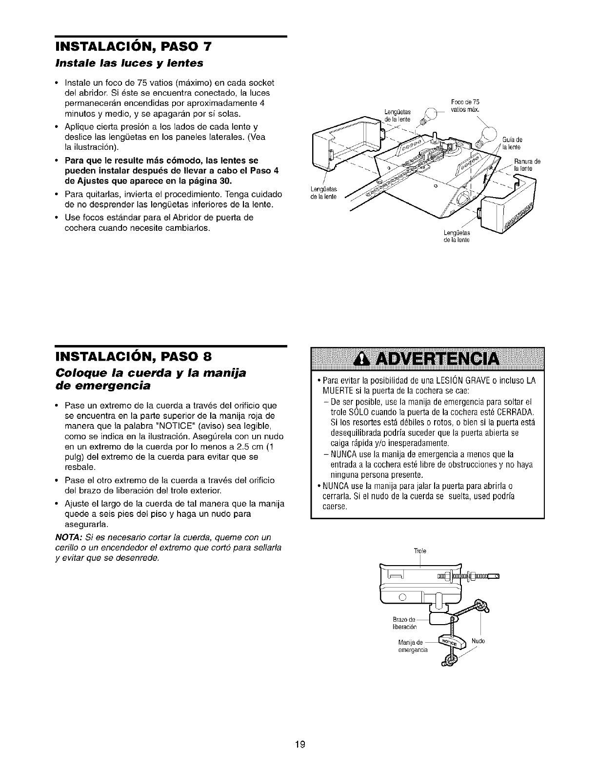
INSTALACION, PASO 7
Instale las luces y lentes
•Instale un foco de 75 vatios (maximo) en cada socket
del abridor. Si este se encuentra conectado, la luces
permanecer_.n encendidas por aproximadamente 4
minutos y medio, y se apagaran por si solas.
• Aplique cierta presion a los lades de cada lente y
deslice las lengQetas en los paneles laterales. (Vea
la ilustracion).
•Para que le resulte m_s e6modo, las lentes se
pueden instelar despu_s de Ilevar aeabo el Paso 4
de Ajastes que apareee en la p_gina 30.
• Para quitarlas, invierta el procedimiente. Tenga cuidado
de no desprender las lengQetas inferieres de la lente.
• Use foces estandar para el Abridor de puerta de
cechera cuande necesite cambiados.
Lengeetas
delalente
Lengeetas
F0c0de 75
vati0s m_
J
LengSetas
delalente
Guia de
lalente
Ranurade
INSTALACION, PASO 8
Coloque la cuerda y la manija
de emergencia
• Pase un extreme de la cuerda a traves del orificio que
se encuentra en la parte superior de la manija roja de
manera que la palabra "NOTICE" (aviso) sea legible,
como se indica en la ilustraci6n. Asegurela con un nudo
en un extremo de la cuerda por Io menos a 2.5 cm (1
pulg) del extremo de la cuerda para evitar que se
resbale.
• Pase el otro extreme de la cuerda a trav_,s del orificio
del braze de liberacion del trole exterior.
• Ajuste el largo de la cuerda de tal manera que la manija
quede a seis pies del piso y haga un nudo para
asegurarla.
NOTA: Si es necesario cortar la cuerda, queme con un
ceri!lo o un encendedor e! extremo que cortd para sellarla
y evitar que se desenrede.
• Para evitar la posibilidad de una LESIONGRAVEo incluso LA
MUERTEsi la puerta de la cochera se cae:
De ser posible use la manija de emergencia para soltar el
trole SOLOcuando la puerta de la cochera est_ CERRADA
Si los resortes est_ d6biles o rotos o bien si la puerta estd
desequilibrada podria suceder que la puerta abierta se
caiga r_pida y/o inesperadamente
NUNCAuse la manija de emergenciaa menos que la
entrada a la cochera est_ libre de obstrucciones y no haya
ninguna persona presente
• NUNCA use la manija parajalar la puerta paraabrirla o
cerrarla Si el nudo de la cuerda se suelta used podria
caerse
Tr01e
liberaci6n
Nudo
emergencia
19
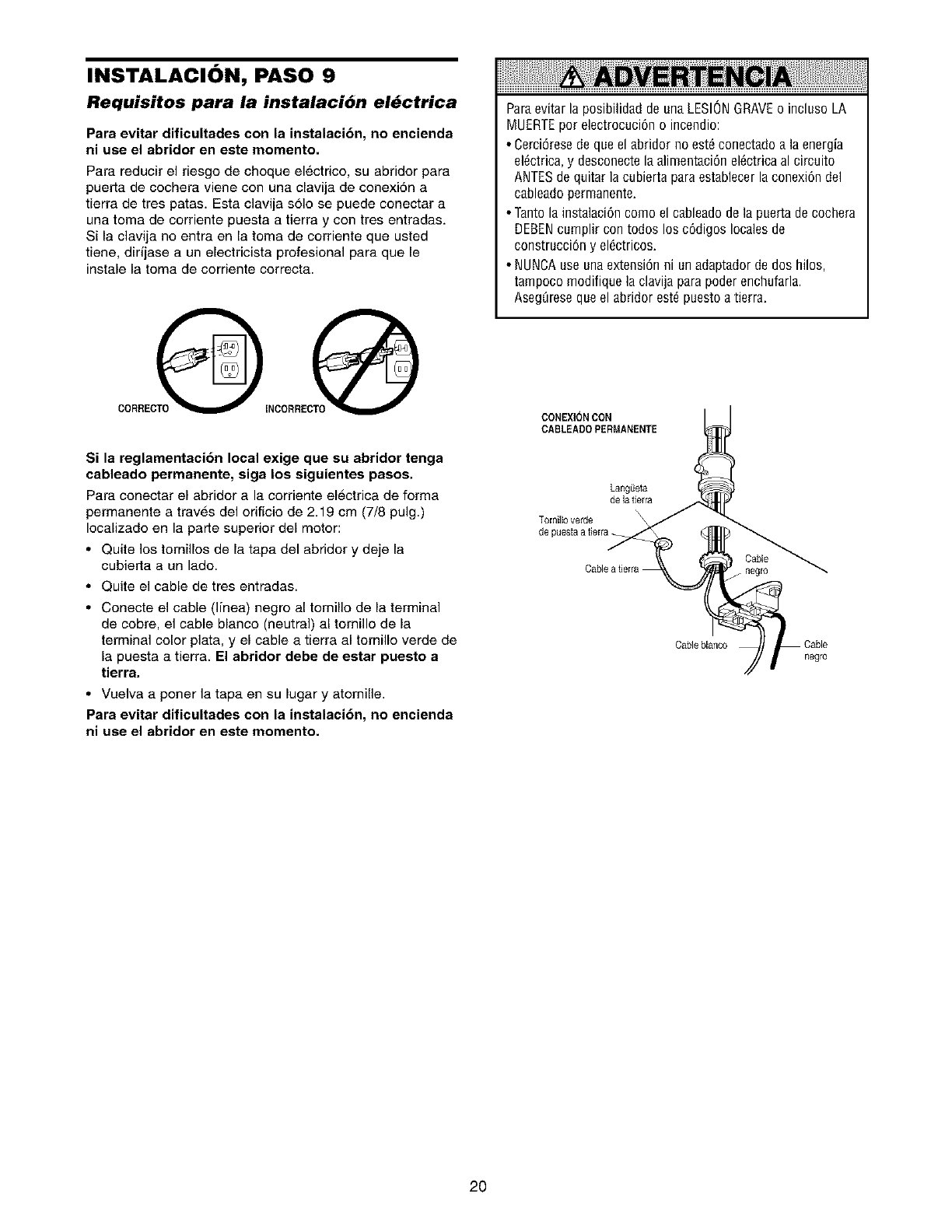
INSTALACION, PASO 9
Requisitos para la instalaci6n el_ctrica
Para evitar dificultades con la instalaci6n, no encienda
ni use el abridor en este momento.
Para reducir el riesgo de choque el6ctrico su abridor para
puerta de cochera viene con una clavija de conexiSn a
tierra de tres patas Esta clavija solo se puede conectar a
una toma de corriente puesta a tierra y con tres entradas
Si la clavija no entra en la toma de corriente que usted
tiene dirfjase a un electricista profesional para que le
instale la toma de corriente correcta
CORRECOINCORRECTO_
Si la reglamentaci6n local exige que su abridor tenga
cableado permanente, siga los siguientes pasos.
Para conectar el abridor a la corriente electrica de forma
permanente a traves del orificio de 2 19 cm (7/8 pulg)
Iocalizado en la parte superior del motor:
• Quite los tornillos de la tapa del abridor y deje la
cubierta a un lado
• Quite el cable de tres entradas
• Conecte el cable (Ifnea) negro al tornillo de la terminal
de cobre el cable blanco (neutral) al tornillo de la
terminal color plata y el cable a tierra al tornillo verde de
la puesta a tierra El abridor debe de estar puesto a
tierra
• Vuelva a poner la tapa en su lugar y atornille
Para evitar dificultades con la instalaci6n, no encienda
ni use el abridor en este momento
ParaevitarlaposibilidaddeanaLESIONGRAVEo inclusoLA
MUERTEporelectrocuci6no incendio
• Cerci6resedeqaeel abridornoest6conectadoa laenergia
el6ctricay desconectelaalimentaci6nel_ctricaal circuito
ANTESdequitarlacubiertaparaestablecerlaconexi6ndel
cableadopermanente
• Tantola instalaci6ncomoel cableadodela paertadecochera
DEBENcamplircontodoslos c6digoslocalesde
construcci6ny el6ctricos
• NUNCAuseunaextensi6nni anadaptadorde doshilos
tampocomodifiquelaclavijaparapoderenchufarla
AsegOresequeel abridorest6puestoatierra
CONEXION CON
CABLEADO PERMANENTE
Lang_eta
delatierra
Tomillo verde
de puestaa tierra
Cable
/ negro
Cable blanco
negro
2O
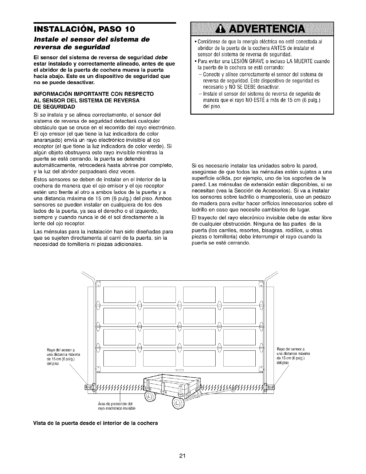
INSTALACION, PASO 10
Instale el sensor del sistema de
reversa de seguridad
El sensor del sistema de reversa de seguridad debe
estar instalado y correctamente alineado, antes de que
el abridor de la puerta de cochera mueva la puerta
hacia abajo. Este es un dispositivo de seguridad que
no se puede desactivar.
INFORMACI(_N IMPORTANTE CON RESPECTO
AL SENSOR DEL SISTEMA DE REVERSA
DE SEGURIDAD
Si se instala y se alinea correctamente, el sensor del
sistema de reversa de seguridad detectara cualquier
obstAculo que se cruce en el recorrido del rayo electr6nico.
El ojo emisor (el que tiene la luz indicadora de color
anaranjado) envfa un rayo electronico invisible al ojo
receptor (el que tiene la luz indicadora de color verde). Si
algt]n objeto obstruyera este rayo invisible mientras la
puerta se esta cerrando, la puerta se detendr_.
automAticamente, retrocedera basra abrirse por complete,
y la luz del abridor parpadeara diez veces.
Estos sensores se deben de instalar en el interior de la
cochera de manera que el ojo emisor y el ojo receptor
esten uno frente al etro a ambos lados de la puerta y a
una distancia maxima de 15 cm (6 pulg.) del piso. Ambos
sensores se pueden instalar en cualquiera de los dos
lados de la puerta, ya sea el derecho o el izquierdo,
siempre y cuando nunca le d6 el sol directamente a la
lente del ojo receptor.
Las m6nsulas para la instalaci6n ban sido disefiadas para
que se sujeten directamenta al carril de la puerta, sin la
necesidad de ternilleria ni piezas adicienales.
•Cerci6rese de que la energia el6ctrica no est6 conectada al
abridor de la puerta de la cochera ANTESde instalar el
sensor del sistema de reversa de seguridad.
• Para evitar una LESl6N GRAVEo incluso LA MUERTEcuando
la puerta de la cochera se est_ cerrando:
- Conectey alinee correctamente el sensor del sistema de
reversa de seguridad. Estedispositivo de seguridad es
necesario y NOSE DEBEdesactivar.
- Instale el sensor del sistema de reversa desegurida de
manera que el rayo NO ESTEa m_s de 15 cm (6 pulg)
del piso
Si es necesario instalar las unidades sobre la pared,
asegdlrese de que todes las mensulas est6n sujetas a una
superficie solida, por ejemple, uno de los soportes de la
pared. Las mensulas de extensi6n est_.n disponibles, si se
necesitan (vea la Seccion de Acceseries). Si va a instalar
los senseres sobre ladrillo e mamposteria, use un pedazo
de madera para evitar hacer erificies innecesarios sobre el
ladrillo en caso que necesite cambiarlos de lugar.
El trayecto del rayo elecr6nice invisible debe de estar libre
de cualquier ebstrucci6n. Ninguna de las partes de la
puerta (los carriles, resortes, bisagras, redillos, u otras
piezas o tornillerfa) debe interrumpir el rayo cuando la
puerta se este cerrando.
A[ea de protecci6ndel
rayoelectr_nicoinwsible
Vista de la puerta desde el interior de la cochera
21
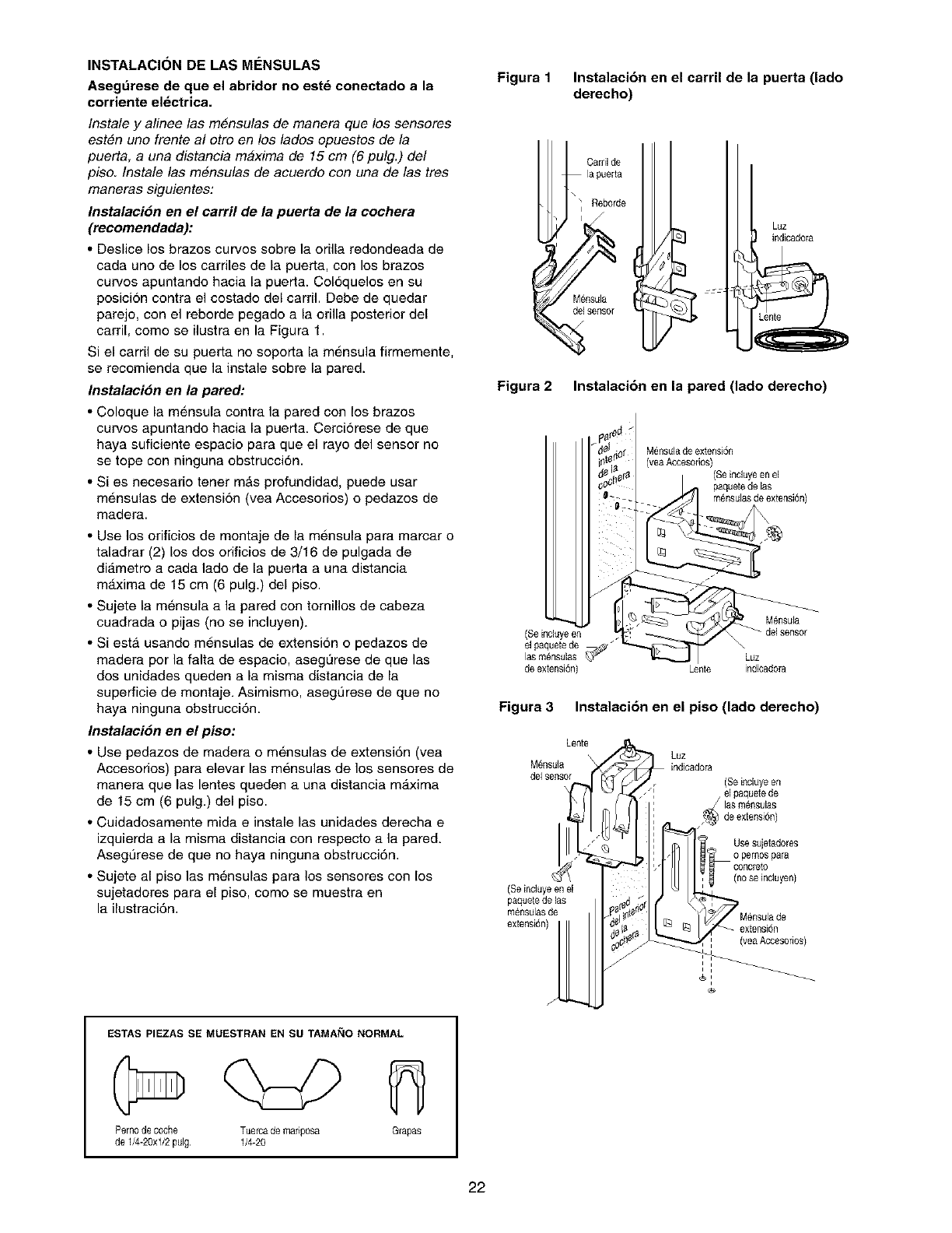
INSTALACION DE LAS M#:NSULAS
Asegdrese de que el abridor no est_ conectado a la
corriente el_ctrica.
Instale y alinee las m#nsulas de manera que los sensores
est#n uno frente al otro en los lados opuestos de la
puerta, a una distancia m#xima de 15 cm (6 pulg.) de!
piso. Instale las m#nsulas de acuerdo con una de las tres
maneras siguientes:
Instalaci6n en el carril de la puerta de la cochera
(recomendada):
• Deslice los brazos curves sobre la orilla redondeada de
cada uno de los carriles de la puerta, con los brazos
curvos apuntando hacia la puerta. Col6quelos en su
posicion contra el costado del carril. Debe de quedar
parejo, con el reborde pegado a la orilla posterior del
carril, como se ilustra en la Figura 1.
Si el carril de su puerta no soporta la mensula firmemente,
se recomienda que la instale sobre la pared.
Instalaci6n en la pared:
• Coloque la m6nsula contra la pared con los brazos
curvos apuntando hacia la puerta. Cerci6rese de que
haya suficiente espacio para que el rayo del sensor no
se tope con ninguna obstrucci6n.
• Si es necesario tener mAs profundidad, puede usar
mensulas de extensi6n (vea Accesorios) o pedazos de
madera.
• Use los orificios de montaje de la mensula para marcar o
taladrar (2) los dos orificios de 3/16 de pulgada de
di_.metro a cada lado de la puerta a una distancia
maxima de 15 cm (6 pulg.) del piso.
• Sujete la m_,nsula a la pared con tomillos de cabeza
cuadrada o pijas (no se incluyen).
• Siesta usando mensulas de extensi6n o pedazos de
madera por la falta de espacio, asegL_rese de que las
dos unidades queden a la misma distancia de la
superficie de montaje. Asimismo, asegL]rese de que no
haya ninguna obstrucci6n.
Instalaci6n en el piso:
• Use pedazos de madera o m6nsulas de extensi6n (vea
Accesorios) para elevar las mensulas de los sensores de
manera que las lentes queden a una distancia maxima
de 15 cm (6 pulg.) del piso.
• Cuidadosamente mida e instale las unidades derecha e
izquierda a la misma distancia con respecto a la pared.
Asegt]rese de que no haya ninguna obstrucci6n.
• Sujete al piso las m_,nsulas para los sensores con los
sujetadores para el piso, como se muestra en
la ilustraci6n.
ESTAS PIEZAS SE MUESTRAN EN SU TAMANO NORMAL
Pern0de c0che Tuercade mafip0sa Grapas
de 1/4-20xl/2 pulg 1/4-20
Figura 1Instalaci6n en el carril de la puerta (lado
derecho)
Carril de
la puerta
M_nsula
delsensor
Luz
indicadora
Figura 2Instalaci6n en la pared (lado derecho)
(Seincluyeen
el paquetede
lasmensulas
de extensi6n)
IS
d_j_
i
Mensulade extensi6n
(veaAccesorios)
_JJJ
Lente indicadora
Figura 3Instalaci6n en el piso (lado derecho)
Lente
Luz
M_nsula
delsensor
jl
(Seincluye enel
paquetede las
mCnsulasde
extensi6n)
(Seincluye en
el paquetede
Use sujetad0res
0 pem0s para
(noseincluyen)
extensi6n
(yea Accesofios)
i
i
i
J
22
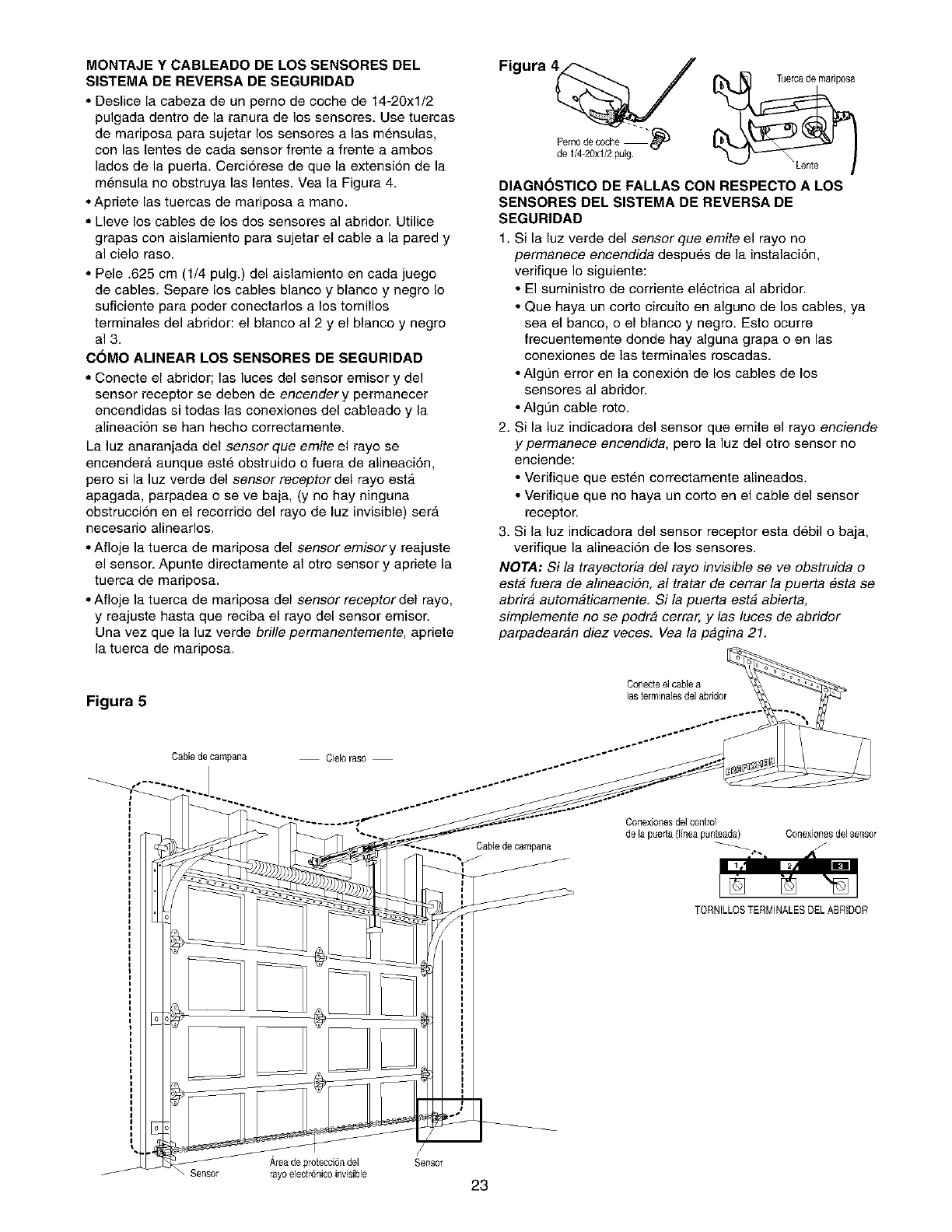
MONTAJE Y CABLEADO DE LOS SENSORES DEL
SISTEMA DE REVERSA DE SEGURIDAD
• Deslice la cabeza de un pemo de coche de 14-20xl/2
pulgada dentro de la ranura de los sensores. Use tuercas
de mariposa para sujetar los sensores alas mensulas,
con las lentes de cada sensor frente a frente a ambos
lados de la puerta. Cerciorese de que la extension de la
mensula no obstruya las lentes. Vea la Figura 4.
• Apriete las tuercas de mariposa a mane.
• Lleve los cables de los dos sensores al abridor. Utilice
grapas con aislamiento para sujetar el cable a la pared y
al cielo raso.
• Pele .625 cm (1/4 pulg.) del aislamiento en cada juego
de cables. Separe los cables blanco y blanco y negro Io
suficiente para poder conectarlos a los tomillos
terminales del abridor: el blanco al 2 y el blanco y negro
al 3.
COMO ALINEAR LOS SENSORES DE SEGURIDAD
• Conecte el abridor; las luces del sensor emisor y del
sensor receptor se deben de encender y permanecer
encendidas si todas las conexiones del cableado y la
alineaci6n se han hecho correctamente.
La luz anaranjada del sensor que emite el rayo se
encendera aunque este obstruido o fuera de alineaci6n,
pero si la luz verde del sensor receptor del rayo est,.
apagada, parpadea o se ve baja, (y no hay ninguna
obstruccion en el recorrido del rayo de luz invisible) ser_
necesario alinearlos.
• Afloje la tuerca de mariposa del sensor emisor y reajuste
el senson Apunte directamente al otro sensor y apriete la
tuerca de mariposa.
• Afloje la tuerca de mariposa del sensor receptor del rayo,
y reajuste hasta que reciba el rayo del sensor emisor.
Una vez que la luz verde bri!le permanentemente, apriete
la tuerca de mariposa.
Figura 5
Cable de campana Ciel0 raso
Figura 4
Pern0dec0che - "_
de 1/4-20xl/2pulg.
DIAGNOSTICO DE FALLAS CON RESPECTO A LOS
SENSORES DEL SISTEMA DE REVERSA DE
SEGURIDAD
1. Si la luz verde del sensor que emite el rayo no
permanece encendida despu_,s de la instalaci6n,
verifique Io siguiente:
• El suministro de corriente el6ctrica al abridor.
• Que haya un corto circuito en alguno de los cables, ya
sea el banco, o el blanco y negro. Esto ocurre
frecuentemente donde hay alguna grapa o en las
conexiones de las terminales roscadas.
• AIgt]n error en la conexion de los cables de los
sensores al abridon
• AIgt]n cable roto.
2. Si la luz indicadora del sensor que emite el rayo enciende
y permanece encendida, pero la luz del otro sensor no
enciende:
• Verifique que esten correctamente alineados.
• Verifique que no haya un corto en el cable del sensor
receptor.
3. Si la luz indicadora del sensor receptor esta debil o baja,
verifique la alineaci6n de los sensores.
NOTA: Si la trayectoria de! rayo invisible se ve obstruida o
est& fuera de alineacidn, al tratar de cerrar la puerta esta se
abrira automaticamente. Si la puerta esta abierta,
simplemente no se podra cerrar, y las luces de abridor
parpadearan diez veces. Vea la pagina 21.
Conecte el cable a
las terminales de] abridor
Cablede campana
C0nexi0nesdel c0ntr01
de la puerta (Ifneapunteada) Conexionesdel sensor
TORNILLOSTERMINALESDEL ABRIDOR
Areade protecci6ndel Sensor
Sensor rayoelectr6nicoinvisible 23
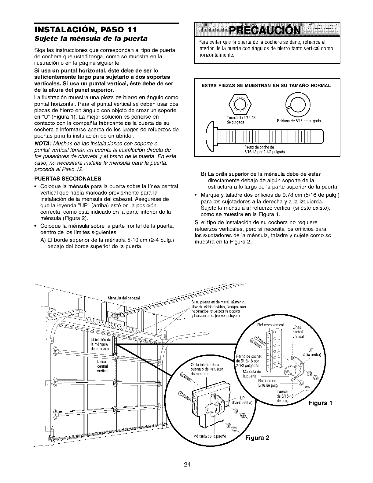
INSTALACION, PASO 11
Sujete la m_nsula de la puerta
Siga las instrucciones que correspondan al tipo de puerta
de cochera que usted tenga, come se muestra en la
ilustraci6n o en la p_.gina siguiente.
Si usa un puntal horizontal, _ste debe de ser Io
sufieientemente largo para sujetarlo a dos soportes
vertieales. Si usa un puntal vertical, _ste debe de set
de la altura del panel superior.
La ilustraci6n muestra una pieza de hierro en angulo come
puntal horizontal. Para el puntal vertical se deben usar dos
piezas de hierro en angulo con objeto de crear un soporte
en "U" (Figura 1). La mejor soluci6n es ponerse en
contacto con la compaRia fabricante de la puerta de su
cochera einformarse acerca de los juegos de refuerzos de
puertas para la instalaci6n de un abridor.
NOTA: Muchas de las instalaciones con soporte o
puntal vertical toman en cuenta la instalacion directa de
los pasadores de chaveta y e! brazo de la puerta. En este
caso, no necesitara instalar la mensula para la puerta;
proceda al Paso 12.
PUERTAS SECCIONALES
•Coloque la mensula para la puerta sobre la linea central
vertical que habia marcado previamente para la
instalaci6n de la m6nsula del cabeza]. Asegurese de
que la leyenda "UP" (arriba) est_ en la posici6n
correcta, como esta. indicado en la parte interior de la
mensula (Figura 2).
• Coloque la mensula sobre la parte frontal de la puerta,
dentro de los limites siguientes:
A) El borde superior de la m6nsula 5-10 cm (2-4 pulg.)
debajo del borde superior de la puerta.
Paraevitar que la puerta de la cochera se da5e, refuerceel
interior de la puerta con _ngulos de hierro tanto vertical como
horizontalmente.
ESTASPIEZASSE MUESTRANEN SU TAMAI_IO NORMAL
de pulgada Roldanade5/16 de pulgada
Pemode coche de
5/16-16por 2-1/2pulgada
B) La orilla superior de la mensula debe de estar
directamente debajo de algL_nsoporte de la
estructura a Io largo de la parte superior de la puerta.
• Marque y taladre dos orificios de 0.78 cm (5/16 de pulg.)
para los sujetadores a la derecha y a la izquierda.
Sujete la md,nsula al refuerzo vertical (si d,ste existe),
come se muestra en la Figura 1.
Si el tipo de instalaci6n de su cochera no requiere
refuerzos verticales, pero si necesita los orificios para
los sujetadores de la mensula, taladre y sujete come se
muestra en la Figura 2.
Mensuladel cabezal
Si su puerta esde metal, aluminio,
fibra de vidrioo vidno, siempre son
rlecesario$refLlerzosveriica[es
Figura 1
ura 2
24
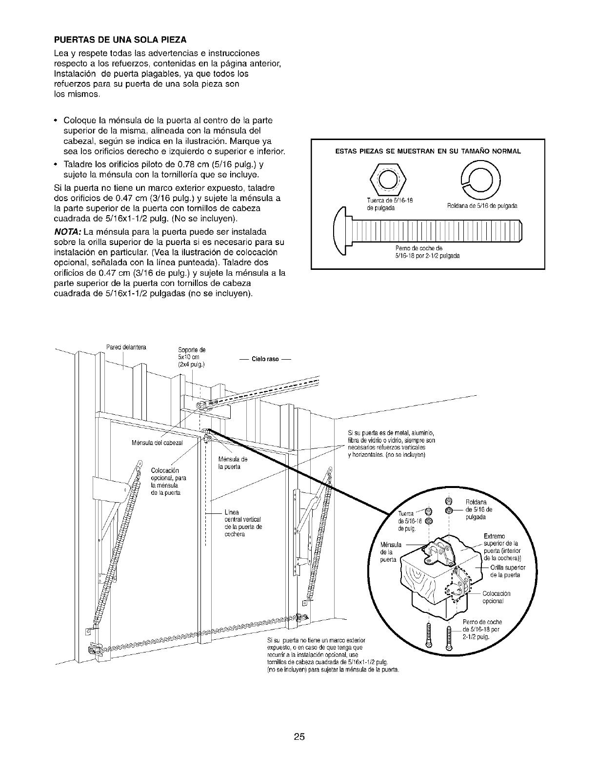
PUERTAS DE UNA SOLA PIEZA
Lea y respete todas las advertencias e instrucciones
respecto a los refuerzos, contenidas en la pAgina anterior,
Instalaci6n de puerta plagables, ya que todos los
refuerzos para su puerta de una sola pieza son
los mismos.
• Coloque la mensula de la puerta al centro de la parte
superior de la misma, alineada con la mensula del
cabezal, segL_nse indica en la ilustracion. Marque ya
sea los orificios derecho e izquierdo o superior e inferior.
• Taladre los orificios piloto de 0.78 cm (5/16 pulg.) y
sujete la mensula con la tornillerfa que se incluye.
Si la puerta no tiene un marco exterior expuesto, taladre
dos orificios de 0.47 cm (3/16 pulg.) y sujete la mensula a
la parte superior de la puerta con tornillos de cabeza
cuadrada de 5/16x1-1/2 pulg. (No se incluyen).
NOTA: La mensula para la puerta puede ser instalada
sobre la orilla superior de la puerta si es necesario para su
instalacion en particular. (Vea la ilustracion de colocacion
opcional, se5alada con la Ifnea punteada). Taladre dos
orificios de 0.47 cm (3/16 de pulg.) y sujete la m_,nsula a la
parte superior de la puerta con tornillos de cabeza
cuadrada de 5/16x1-1/2 pulgadas (no se incluyen).
ESTAS PIEZAS SE MUESTRAN EN SU TAMANO NORMAL
de pulgada R01danade 5/16 de pulgada
Pernode c0che de
5/16-18p0r2-1/2 pulgada
Pareddelantera Soporte de
5x10 cm
(2x4 pulg) Cieloraso
Mensuladel cabezal
Colocaci6n
opcional, para
la mensula
dela puerta
Mensulade
la puerta
Linea
centralveflical
de la puefla de
cochera
Si su puertaes de metal,aluminio,
fibra de viddoo vidrio, siempre son
y hodzontales (no seincluyen)
Mensula
de]a _
pue_a
Si su puerta no tiene un marcoexterior
expuesto, oen caso de que tengaque
recurdra la instalaci6nopcional,use
tomillos de cabezacuadradade 5/16xl -1/2pulg.
(no se incluyen)para sujetarla m@nsulade la puerta
_ oldana
de 5/16de
, pulgada
i
E×/remo
f superior dela
..., puerta(interior
_lde la cochera))
Orilla superior
_de la puerta
Colocaci6n
opcional
Perno decoche
25
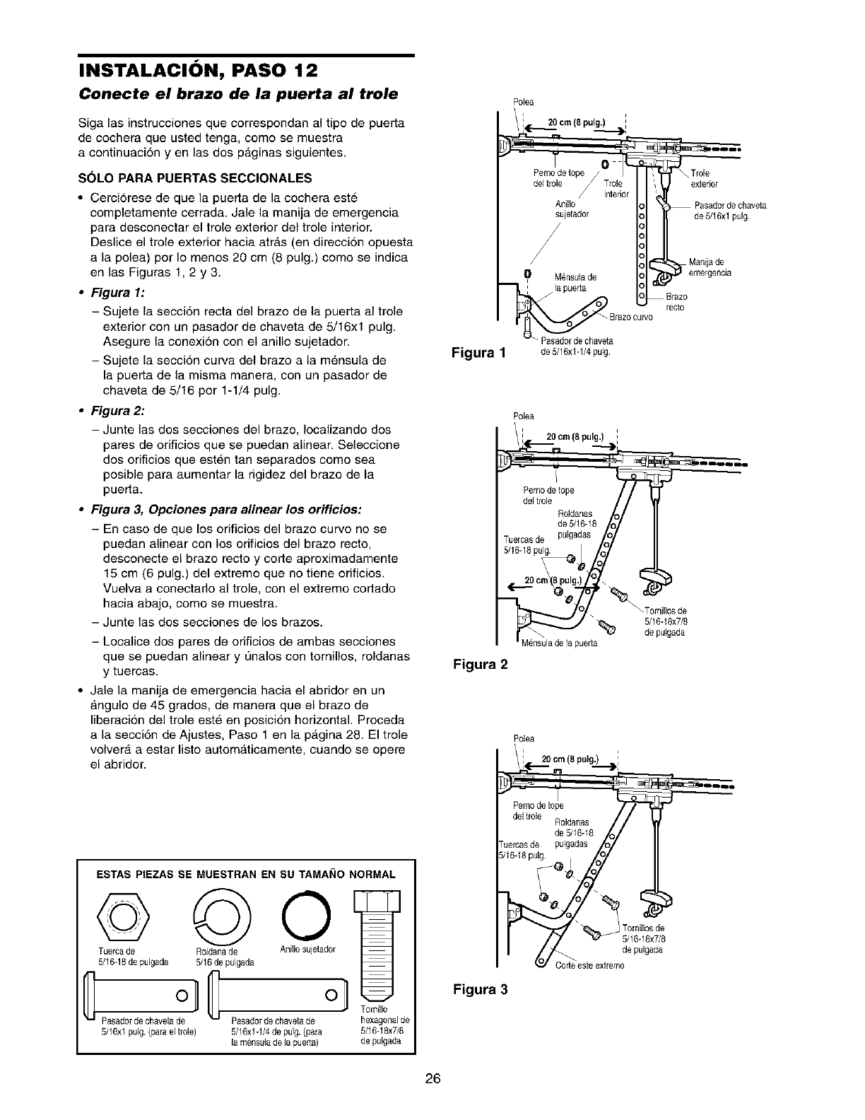
INSTALACION, PASO 12
Conecte el brazo de la puerta al trole
Siga las instrucciones que correspondan al tipo de puerta
de cochera que usted tenga, come se muestra
a continuacion yen las dos p_.ginas siguientes.
SOLO PARA PUERTAS SECCIONALES
•Cerciorese de que la puerta de la cochera este
completamente cerrada. Jale la manija de emergencia
para desconectar el trole exterior del trole interior.
Deslice el trole exterior hacia atrfis (en direccion opuesta
a la polea) por Io menos 20 cm (8 pulg.) como se indica
en las Figuras 1, 2 y 3.
•Figura I:
- Sujete la seccidn recta del braze de la puerta al trole
exterior con un pasador de chaveta de 5/16xl pulg.
Asegure la conexion con el anillo sujetador.
- Sujete la seccidn curva del brazo a la m6nsula de
la puerta de la misma manera, con un pasador de
chaveta de 5/16 per 1-1/4 pulg.
•Figura 2:
-Junte las dos secciones del brazo, Iocalizando dos
pares de orificios que se puedan alinear. Seleccione
dos orificios que esten tan separados como sea
posible para aumentar la rigidez del brazo de la
puerta.
•Figura 3, Opciones para alinear los orificios:
- En case de que los orificios del braze curve no se
puedan alinear con los orificios del braze recto,
desconecte el brazo recto y corte aproximadamente
15 cm (6 pulg.) del extreme que no tiene orificios.
Vuelva aconectarlo al trole, con el extremo cortado
hacia abajo, como se muestra.
- Junte las dos secciones de los brazes.
-Localice dos pares de orificios de ambas secciones
que se puedan alinear y L_naloscon tornillos, roldanas
y tuercas.
• Jale la manija de emergencia hacia el abridor en un
fingulo de 45 grados, de manera que el braze de
liberacion del trole este en posicion horizontal. Proceda
a la secci6n de Ajustes, Paso 1 en la pfigina 28. El trole
volver_, a estar listo automfiticamente, cuando se opere
el abridor.
ESTAS PIEZAS SE MUESTRAN EN SU TAMANO NORMAL
© © 0
Tuercade Roldanade Anillosujetador
5/16-18de pulgada 5/16 de pulgada
Co o
Pasad0rde chaveta de Pasad0r de chaveta de hexagonalde
5/16xl pulg (para el tr01e) 5/16x1-1/4de pulg. (para 5/16-18x7/8
la m_nsulade la puerta) de pulgada
Polea
i
20 cm (8 pulg,) :
. _ -_ --_t,
_ _ . ....
Pernode tope/ / ', Trole
del tr01e Tr01e '_ exterior
interior
Anillo Pasadorde chaveta
sujetad0r de5/16xl pulg.
/
/
/Manijade
Mensulade
:la puerta
recto
Figura 1 de5/16x1-1/4pulg
Polea
i20 cm (8 pulg.)
___,., "--3,
Pemode tope
del trole
Roldanas
de 5/16-18 o
5Jle6rclassdueg pulgadas o
Figura 2
l
_ Tomillos de
5/16-18x7/8
de pulgada
Polea
i28cm (8pulg.) ,
7
del Irole Roldanas
de 5/16-18
"uercasde pulgadas
;/1648 pulg _!_
Tornillos de
de pulgada
, '
Figura 3
26
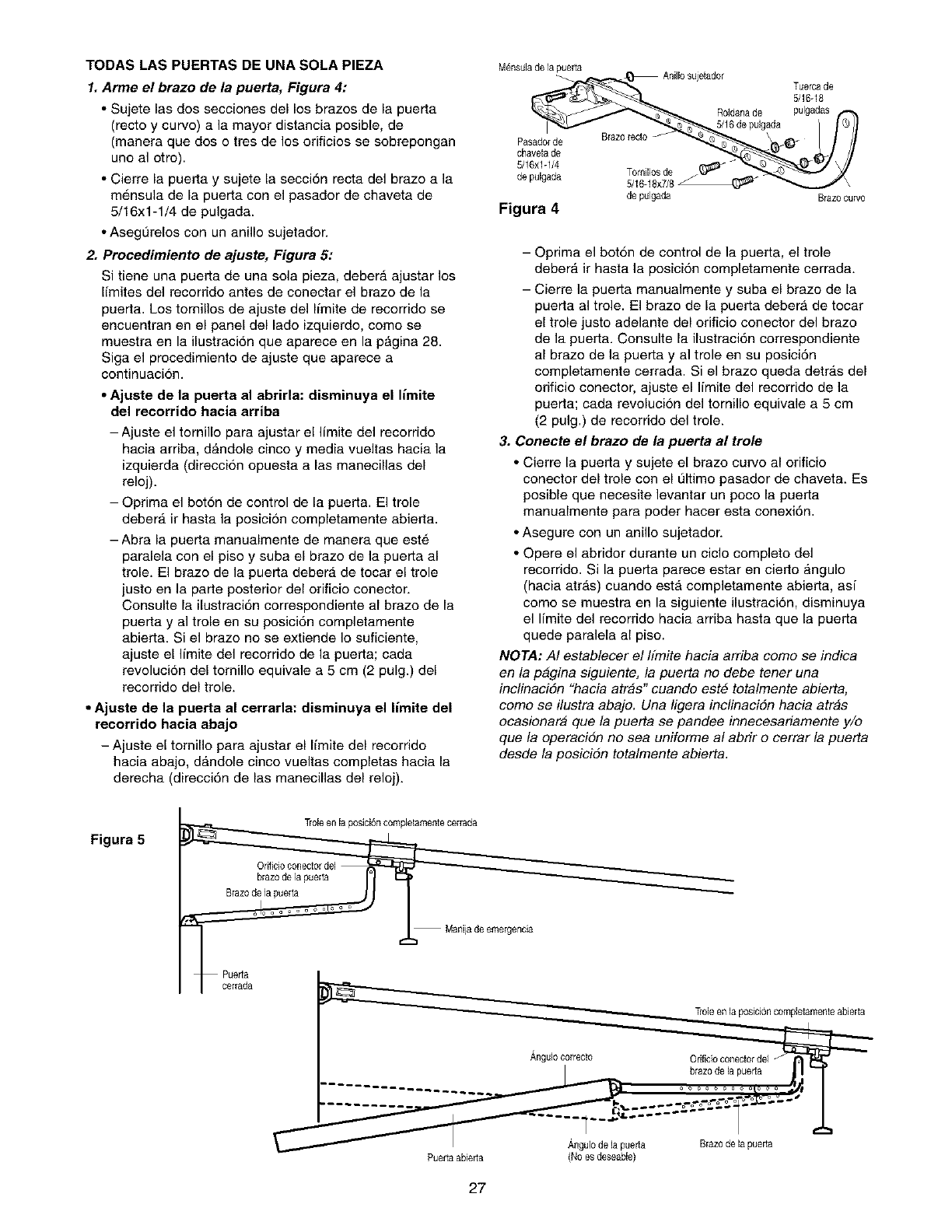
TODAS LAS PUERTAS DE UNA SOLA PIEZA
1. Arme el brazo de la puerta, Figura 4:
• Sujete las dos secciones del los brazos de la puerta
(recto y curvo) a la mayor distancia posible, de
(manera que dos o tres de los orificios se sobrepongan
uno al otro).
• Cierre la puerta y sujete la secci6n recta del brazo a la
mensula de la puerta con el pasador de chaveta de
5/16x1-1/4 de pulgada.
• AsegL_relos con un anillo sujetador.
2. Procedimiento de ajuste, Figura 5:
Si tiene una puerta de una sola pieza, deber_, ajustar los
limites del recorrido antes de conectar el brazo de la
puerta. Los tomillos de ajuste del limite de recorrido se
encuentran en el panel del lado izquierdo, como se
muestra en la ilustraci6n que aparece en la p_gina 28.
Siga el procedimiento de ajuste que aparece a
continuaci6n.
•Ajuste de la puerta al abrirla: disminuya el limite
del recorrido hacia arriba
-Ajuste el tornillo para ajustar el limite del recorrido
hacia arriba, dAndole cinco y media vueltas hacia la
izquierda (direcci6n opuesta alas manecillas del
reloj).
- Optima el bot6n de control de la puerta. El trole
debera ir hasta la posici6n completamente abierta.
- Abra la puerta manualmente de manera que est',
paralela con el piso y suba el brazo de la puerta al
trole. El brazo de la puerta deber_, de tocar el trole
justo en la parte posterior del orificio conector.
Consulte la ilustraci6n correspondiente al braze de la
puerta y al trole en su posici6n completamente
abierta. Si el brazo no se extiende Io suficiente,
ajuste el limite del recorrido de la puerta; cada
revoluci6n del tornillo equivale a 5 cm (2 pulg.) del
recorrido del trole.
•Ajuste de la puerta al cerrarla: disminuya el limite del
recorrido hacia abajo
- Ajuste el tornillo para ajustar el limite del recorrido
hacia abajo, dandole cinco vueltas completas hacia la
derecha (direcci6n de las manecillas del reloj).
M_nsulade la puerta Anill0 sL_jetador z
5/16-18
Roldanade pulgadas
5/16 depulgada
Pa _)-
0h v0ta o e-/, //
5/16x1-1/4
de p_lgada Brazocurvo
Figura 4
-Optima el bot6n de control de la puerta, el trole
deber_, ir hasta la posici6n completamente cerrada.
- Cierre la puerta manualmente y suba el brazo de la
puerta al trole. El brazo de la puerta deber_ de tocar
el trole justo adelante del orificio conector del brazo
de la puerta. Consulte la ilustraci6n correspondiente
al brazo de la puerta y al trole en su posici6n
completamente cerrada. Si el brazo queda detr_.s del
orificio conector, ajuste el limite del recorrido de la
puerta; cada revoluci6n del tornillo equivale a 5 cm
(2 pulg.) de recorrido del trole.
3. Conecte el brazo de la puerta al trole
• Cierre la puerta y sujete el brazo curvo al orificio
conector del trole con el L_ltimopasador de chaveta. Es
posible que necesite levantar un poco la puerta
manualmente para poder hacer esta conexi6n.
• Asegure con un anillo sujetador.
• Opere el abridor durante un ciclo completo del
recorrido. Si la puerta parece estar en cierto angulo
(hacia atr_s) cuando esta completamente abierta, asi
como se muestra en la siguiente ilustraci6n, disminuya
el limite del recorrido hacia arriba hasta que la puerta
quede paralela al piso.
NOTA: AI establecer el Ifmite hacia arriba como se indica
en la pagina siguiente, la puerta no debe tener una
inclinacidn "hacia atras" cuando este totalmente abierta,
como se ilustra abajo. Una ligera inclinacidn hacia atras
ocasionara que la puerta se pandee innecesariamente y/o
que la operacion no sea uniforme al abrir o cerrar la puerta
desde la posicion totalmente abierta.
Figura 5
Troleen la posici6n complelamentecerrada
Puertaabierta Angulo de la puerta Brazo de la puerta
(Noes deseable)
27
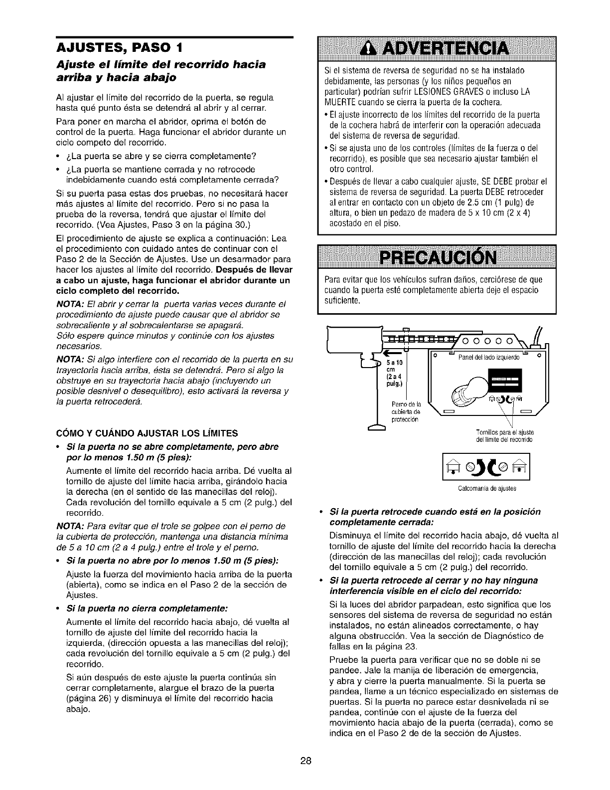
AJUSTES, PASO 1
Ajuste el limite del recorrido hacia
arriba y hacia abajo
AI ajustar el limite del recorrido de la puerta, se regula
hasta que punto esta se detendra al abrir y al cerrar.
Para poner en marcha el abridor, oprima el bot6n de
control de la puerta. Haga funcionar el abridor durante un
ciclo competo del recorrido.
•&La puerta se abre y se cierra completamente?
• &La puerta se mantiene cerrada y no retrocede
indebidamente cuando esta completamente cerrada?
Si su puerta pasa estas dos pruebas, no necesitara hacer
m_.s ajustes al limite del recorrido. Pero si no pasa la
prueba de la reversa, tendr_, que ajustar el limite del
recorrido. (Vea Ajustes, Paso 3 en la p_.gina 30.)
El procedimiento de ajuste se explica a continuaci6n: Lea
el procedimiento con cuidado antes de continuar con el
Paso 2 de la Secci6n de Ajustes. Use un desarmador para
hacer los ajustes al limite del recorrido. Despu_s de Ilevar
a cabo un ajuste, haga funcionar el abridor durante un
ciclo completo del recorrido.
NOTA: El abrir y cerrar la puerta varias veces durante e!
procedimiento de ajuste puede causar que e! abridor se
sobrecaliente y al sobrecalentarse se apagar&
Sd!o espere quince minutos y continue con los ajustes
necesarios.
NOTA: Si algo interfiere con e! recorrido de la puerta en su
trayectoria hacia arriba, #sta se detendra. Pero si algo la
obstruye en su trayectoria hacia abajo (incluyendo un
posible desnive! o desequilibro), esto activara la reversa y
la puerta retrocedera.
C(_MO Y CUANDO AJUSTAR LOS LIMITES
•Si la puerta no se abre completamente, pero abre
por Io menos 1.50 m (5 pies):
Aumente el limite del recorrido hacia arriba. D_ vuelta al
tornillo de ajuste del limite hacia arriba, girandolo hacia
la derecha (en el sentido de las manecillas del reloj).
Cada revolucion del tornillo equivale a 5 cm (2 pulg.) del
recorrido.
NOTA: Para evitar que e! trole se golpee con e! pemo de
la cubierta de proteccidn, mantenga una distancia minima
de 5 a 10 cm (2 a 4 pulg.) entre e! trole y el pemo.
•Si la puerta no abre por Io menos 1.50 m (5 pies):
Ajuste la fuerza del movimiento hacia arriba de la puerta
(abierta), como se indica en el Paso 2 de la seccion de
Ajustes.
• $i la puerta no cierra eompletamente:
Aumente el limite del recorrido hacia abajo, d6 vuelta al
tornillo de ajuste del limite del recorrido hacia la
izquierda, (direcci6n opuesta alas manecillas del reloj);
cada revoluci6n del tomillo equivale a 5 cm (2 pulg.) del
recorrido.
Si aun despu_,s de este ajuste la puerta continua sin
cerrar completamente, alargue el brazo de la puerta
(p_.gina 26) y disminuya el limite del recorrido hacia
abajo.
Si el sistema de reversa de seguridad no se hainstalado
debidamente, las personas (y los niSos pequeSosen
particular) podrian sufrir LESIONESGRAVESo incluso LA
MUERTEcuando se cierra la puerta de la cochera.
• El ajuste incorrecto de los limites del recorrido de la puerta
de la cochera habr_ de interferir con la operaci6n adecuada
del sistema de reversa de seguridad.
• Si se ajusta uno de los controles (limites de la fuerza o del
recorrido), es posible que sea necesario ajustar tambi_n el
otro control.
• Despu6sdeIlevaracabocualquierajuste,SEDEBEprobarel
sistemadereversadeseguridad.LapuertaDEBEretroceder
al entrarencontactocon unobjetode 2,5cm (1 pulg)de
altura,o bienunpedazodemaderade5 x 10cm (2 x 4)
acostadoenelpiso.
Paraevitar que los vehiculos sufran daSos,cerci6rese de que
cuando la puerta est6 completamente abierta deje el espacio
suficiente.
Pemode la
cubieria de
protecci6n
Tomillospara el ajuste
del limite del recorrido
Calcomaniade ajustes
•Si la puerta retrocede cuando est_ en la posici6n
completamente cerrada:
Disminuya el limite del recorrido hacia abajo, d6 vuelta al
tomillo de ajuste del limite del recorrido hacia la derecha
(direccion de las manecillas del reloj); cada revoluci6n
del tomillo equivale a 5 cm (2 pulg.) del recorrido.
•Si la puerta retrocede al cerrar y no hay ninguna
interferencia visible en el ciclo del recorrido:
Si la luces del abridor parpadean, esto significa que los
sensores del sistema de reversa de seguridad no estan
instalados, no estan alineados correctamente, o hay
alguna obstrucci6n. Vea la secci6n de Diagn6stico de
fallas en la pAgina 23.
Pruebe la puerta para verificar que no se doble ni se
pandee. Jale la manija de liberacion de emergencia,
y abra y cierre la puerta manualmente. Si la puerta se
pandea, Ilame a un tecnico especializado en sistemas de
puertas. Si la puerta no parece estar desnivelada ni se
pandea, continL'_econ el ajuste de la fuerza del
movimiento hacia abajo de la puerta (cerrada), como se
indica en el Paso 2 de de la seccion de Ajustes.
28
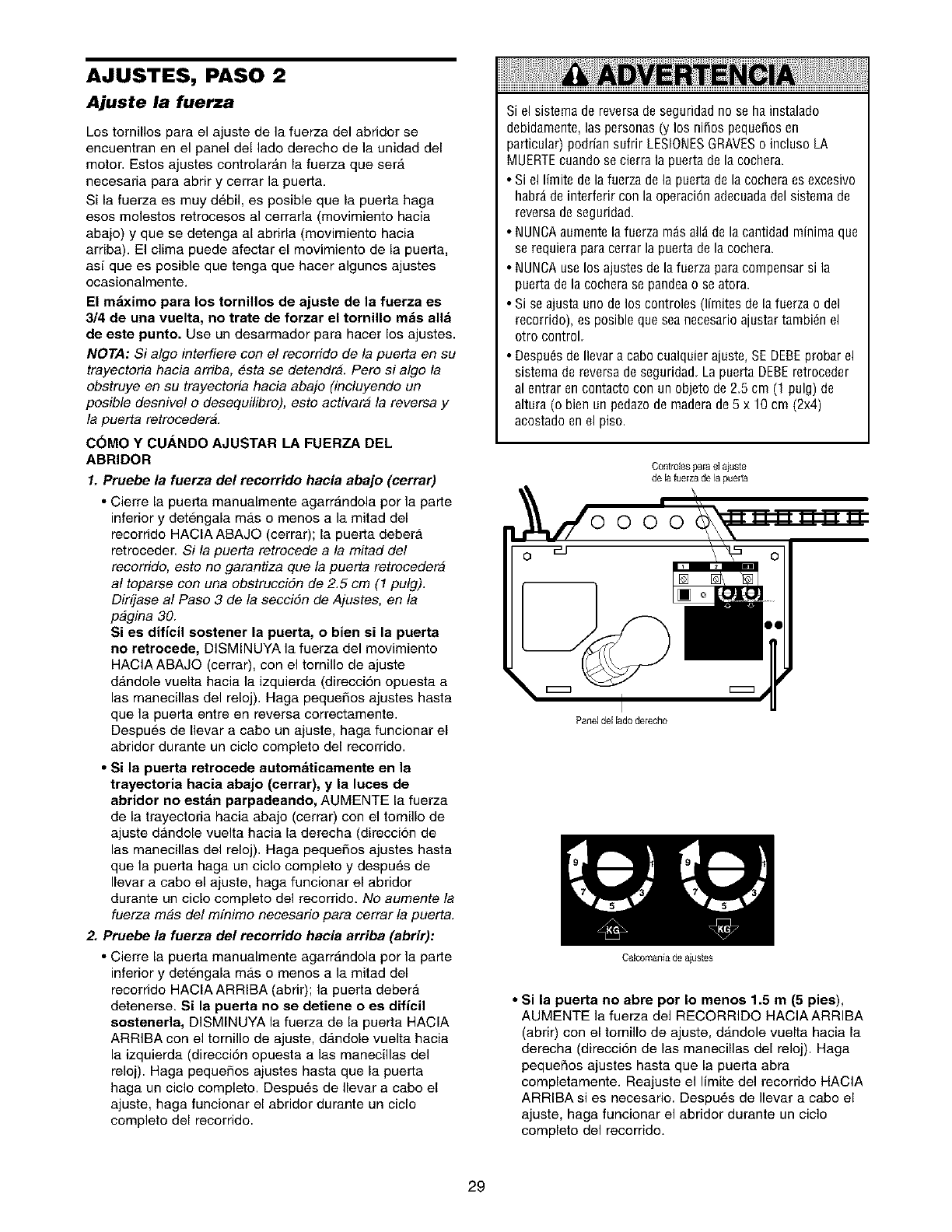
AJUSTES, PASO 2
Ajuste la fuerza
Los tornillos para el ajuste de la fuerza del abridor se
encuentran en el panel del lado derecho de la unidad del
motor. Estos ajustes controlarAn la fuerza que serA
necesaria para abrir y cerrar la puerta.
Si la fuerza es muy d6bil, es posible que la puerta haga
esos molestos retrocesos al cerrarla (movimiento hacia
abajo) y que se detenga al abrirla (movimiento hacia
arriba). El clima puede afectar el movimiento de la puerta,
asi que es posible que tenga que hacer algunos ajustes
ocasionalmente.
El m_ximo para los tornillos de ajuste de la fuerza es
3/4 de una vuelta, no trate de forzar el tornillo m&s alld
de este punto. Use un desarmador para hacer los ajustes.
NOTA: Si algo interfiere con e! recorrido de la puerta en su
trayectoria hacia arriba, esta se detendra. Pero si algo la
obstruye en su trayectoria hacia abajo (incluyendo un
posible desnivel o desequilibro), esto activara la reversa y
la puerta retrocedera.
C(3MO Y CUANDO AJUSTAR LA FUERZA DEL
ABRIDOR
1. Pruebe la fuerza del recorrido hacia abajo (cerrar)
•Cierre la puerta manualmente agarr_.ndola por la parte
inferior y detengala mas o menos a la mitad del
recorrido HACIA ABAJO (cerrar); la puerta debera
retroceder. Si la puerta retrocede a la mitad de!
recorrido, esto no garantiza que la puerta retrocedera
al toparse con una obstruccidn de 2.5 cm (1 pulg).
Dirfjase al Paso 3 de la seccidn de Ajustes, en la
pagina 30.
Si es dificil sostener la puerta, o bien si la puerta
no retrocede, DISMINUYA la fusrza del movimiento
HACIAABAJO (cerrar), con el tornillo de ajuste
dandole vuelta hacia la izquierda (direccion opuesta a
las manecillas del reloj). Haga pequeSos ajustes hasta
que la puerta entre en reversa correctamente.
Despues de Ilevar a cabo un ajuste, haga funcionar el
abridor durante un ciclo completo del recorrido.
• Si la puerta retrocede autem_ticamente en la
trayecteria hacia abajo (cerrar), y la luces de
abrider no est_n parpadeande, AUMENTE la fuerza
de la trayectoria hacia abajo (cerrar) con el tornillo de
ajuste dAndole vuelta hacia la derecha (direccion de
las manecillas del reloj). Haga pequeSos ajustes hasta
que la puerta haga un ciclo completo y despu6s de
Ilevar acabo el ajuste, haga funcionar el abridor
durante un ciclo completo del recorrido. No aumente la
fuerza mas del mfnimo necesario para cerrar la puerta.
2. Pruebe la fuerza del recorrido hacia arriba (abrir):
• Cierre la puerta manualmente agarr_.ndola por la parte
inferior y detengala mas o menos a la mitad del
recorrido HACIA ARRIBA (abrir); la puerta deber_.
detenerse. Si la puerta no se detiene o es dificil
sostenerla, DISMINUYA la fuerza de la puerta HACIA
ARRIBA con el tornillo de ajuste, dandole vuelta hacia
la izquierda (direcci6n opuesta alas manecillas del
reloj). Haga pequeSos ajustes hasta que la puerta
haga un ciclo completo. Despu6s de Ilevar a cabo el
ajuste, haga funcionar el abridor durante un ciclo
completo del recorrido.
Si el sistema de reversa de seguridad no se ha instalado
debidamente, las personas (y los nifios pequeSosen
particular) podrian sufrir LESIONESGRAVESo incluso LA
MUERTEcuando se cierra la puerta de la cochera.
• Si el limite dela fuerza de la puerta de la cochera es excesivo
habrd de interferir con la operaci6n adecuada del sistema de
reversa de seguridad.
• NUNCAaumente la fuerza m_s alld de la cantidad minima que
se requiera para cerrar la puerta de la cochera.
• NUNCAuse los ajustes de la fuerza para compensar si la
puerta de la cochera se pandea o se atora.
• Si se ajusta uno de los controles (limites de la fuerza o del
recorrido), es posible que seanecesario ajustar tambi_n el
otro control.
• Despu6sde Ilevaracabocualquierajuste,SEDEBEprobarel
sistemadereversadeseguridad,LapuertaDEBEretroceder
al entraren contactocon unobjetode2,5cm (1 pulg)de
altura(o bienunpedazodemaderade5 x 10cm (2x4)
acostadoenel piso.
Controlespara el ajuste
de la fuerza de la pueea
Paneldel lado de[echo
Calcomania deaiustes
• Si la puerta no abre per Io menos 1.5 m (5 pies),
AUMENTE la fuerza del RECORRIDO HACIAARRIBA
(abrir) con el tornillo de ajuste, d_.ndole vuelta hacia la
derecha (direcci6n de las manecillas del reloj). Haga
pequeRos ajustes basra que la puerta abra
completamente. Reajuste el limits del recorrido HACIA
ARRIBA si es necesario. Despu_,s de Ilevar a cabo el
ajuste, haga funcionar el abridor durante un ciclo
completo del recorrido.
29
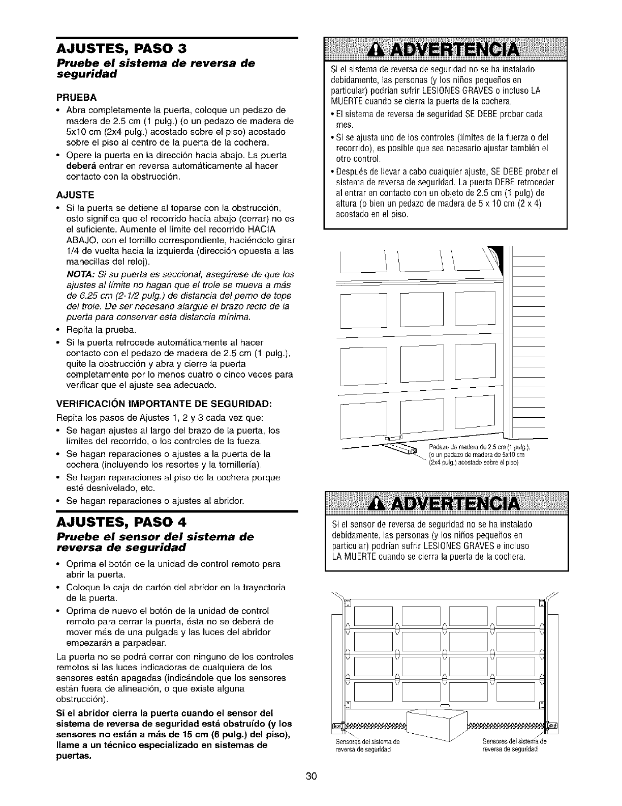
AJUSTES, PASO 3
Pruebe el sistema de reversa de
seguridad
PRUEBA
•Abra completamente la puerta, coloque un pedazo de
madera de 2.5 cm (1 pulg.) (o un pedazo de madera de
5x10 cm (2x4 pulg.) acostado sobre el piso) acostado
sobre el piso al centre de la puerta de la cochera.
•Opere la puerta en la direccion hacia abajo. La puerta
deber_ entrar en reversa automAticamente al hacer
contacto con la obstrucci6n.
AJUSTE
•Si la puerta se detiene al toparse con la obstruccion,
esto significa que el recorrido hacia abajo (cerrar) no es
el suficiente. Aumente el limite del recorrido HACIA
ABAJO, con el tornillo correspondiente, haciendolo girar
1/4 de vuelta hacia la izquierda (direcci6n opuesta alas
manecillas del reloj).
NOTA: Si su puerta es seccional, asegEtrese de que los
ajustes al Ifmite no hagan que el trole se mueva a mas
de 6.25 cm (2-1/2 pulg.) de distancia del pemo de tope
del trole. De ser necesario alargue el brazo recto de la
puerta para conservar esta distancia m[nima.
•Repita la prueba.
• Si la puerta retrocede autom_.ticamente al hacer
contacto con el pedazo de madera de 2.5 cm (1 pulg.),
quite la obstrucci6n y abra y cierre la puerta
completamente per Io menos cuatro o cinco veces para
verificar que el ajuste sea adecuado.
VERIFICACI(_N IMPORTANTE DE SEGURIDAD:
Repita los pasos de Ajustes 1,2 y 3 cada vez que:
• Se hagan ajustes al largo del brazo de la puerta, los
Ifmites del recorrido, o los controles de la fueza.
• Se hagan reparaciones o ajustes a la puerta de la
cochera (incluyendo los resortes y la tornilleria).
• Se hagan reparaciones al piso de la cochera porque
este desnivelado, etc.
• Se hagan reparaciones o ajustes al abridor.
AJUSTES, PASO 4
Pruebe el sensor del sistema de
reversa de seguridad
• Optima el bot6n de la unidad de control remoto para
abrir la puerta.
• Coloque la caja de cart6n del abridor en la trayectoria
de la puerta.
• Optima de nuevo el bot6n de la unidad de control
remoto para cerrar la puerta, esta no se deber_, de
mover m_.s de una pulgada y las luces del abridor
empezaran a parpadear.
La puerta no se podrA cerrar con ninguno de los controles
remotos si las luces indicadoras de cualquiera de los
sensores estan apagadas (indic_.ndole que los sensores
estan fuera de alineaci6n, o que existe alguna
obstruccion).
Si el abridor cierra la puerta cuando el sensor del
sistema de reversa de seguridad est_ obstruido (y los
sensores no est&n a mrs de 15 cm (6 pulg.) del piso),
Ilame a un t_cnico especializado en sistemas de
puertas.
Si el sistema de reversa de seguridad no se hainstalado
debidamente, las personas (y los niSos pequeSosen
particular) podrian sufrir LESIONESGRAVESo incluso LA
MUERTEcuando se cierra la puerta de la cochera.
• El sistema de reversa de seguridad SE DEBEprobar cada
mes.
• Si se ajusta uno de los controles (limites de la fuerza o del
recorrido), es posible que sea necesario ajustar tambi_n el
otro control.
• Despu6sdeIlevaracabocualquierajuste,SEDEBEprobarel
sistemadereversadeseguridad.LapuertaDEBEretroceder
al entrarencontactocon unobjetode 2,5cm (1 pulg)de
altura(o bienun pedazodemaderade5 x 10cm (2x 4)
acostadoenelpiso.
/ \__
JJ
(2x4 pulg.) acostadosobre el piso)
Si el sensor de reversa de seguridad no se ha instalado
debidamente, las personas (y los nifios pequefios en
particular) podrian sufrir LESlONESGRAVESe incluso
LA MUERTEouando se oierra la puerta de la coohera.
Sensoresdel sistemade
reversa deseguddad reversa de seguddad
30
OPERACION
IMPORTANTES INSTRUCCIONES DE SEGURIDAD
Para reducir el riesgo de lesiones graves o la muerte:
1. LEAY RESPETETODAS LASADVERTENCIASY LAS
INSTRUCCIONESDEOPERACION
2. SIEMPREconserve los controles remotos lejos del alcance de
los ni_os. NUNCApermita que los nifios operen o jueguen
con los botones del control de la puerta de la cochera ni con
los controles remotos.
4. SOLOactive la puerta de la cochera siempre y cuando la
puedan ver con claridad, est6 debidamenteajustada y no haya
ninguna obstrucci6n en el recorrido de la puerta al cerrarse.
5. NADIEDEBEPASARPORDEBAJODE LA PUERTASI EST,_
DETENIDAY PARClALMENTEABIERTA.
6. SIEMPREtenga la puerta de la cochera a la vista hasta que
est6 completamente cerrada, nadie debe atravesar el recorrido
dela puerta cuando estA EN MOVIMIENTO.
7. De ser posible, use la liberaci6n deemergencia para soltar el
trole SOLOcuando la puerta de la cochera est6 CERRADA.Si
los resortes estdn d6biles o rotos, o bien si la puerta estd
desequilibradapodria suceder que la puerta se caiga r_pida
y/o inesperadamentecuando est6 abierta.
8. NUNCAuse la manija parajalar la puerta para abrirla o
cerrarla. Si el nudo de lacuerda se suelta, usted podria caerse.
9. Si se ajusta uno de los controles (limites de la fuerza o del
recorrido), es posible que seanecesario ajustar tambi6n el
otro control.
10. Despu6sde Ilevar a cabo cualquier ajuste, SE DEBEprobar
el sistema de reversa de seguridad.
11. Elsistema de reversa de seguridad SE DEBEprobar cada
rues.La puerta DEBEretroceder al entrar en contacto con un
objeto de 2.5 cm (1 pulg) de altura o bien un pedazo de
maderade 5 x 10 cm (2x4) acostado en el piso.
12. SIEMPRE mantenga la puerta de la cochera debidamente
equilibrada (vea la pdgina3). Si la puerta no est_
debidamente equilibrada podrfa no retroceder cuando asf se
requiere, Io que podrfaocasionar una LESIONGRAVEo
incluso la MUERTE.
13. Todas las reparaciones necesarias en los cables, resortes y
otras piezas las DEBEIlevar a cabo un t6cnico especializado
en sistemas de puertas, pues todas estas piezasest_n bajo
unatensi6n EXTREMA.
14. SIEMPRE desconecteel suministro de energia el_ctrica al
abridor de la puerta de la cochera antes de Ilevar a cabo
cualquier reparaci6n o de quitar lascubiertas.
t5.CONSERVE ESTAS INSTRUCCIONES.
C_no usar su abridor de puerta de cochera
Su abridor Security÷ y el control remote manual han sido
pregramados en la fAbrica con un c6dige ceincidente que
cambia cada vez que se usa, accesando al azar m_.s de
100,000 millenes de c6diges nuevos. Su abrider funcienarA
con varies controles remetes Security÷, utilizando hasta 8
funciones y un Sistema de entrada sin Ilave de Security÷.
Si compra un control remoto nuevo, e si desea desactivar
algt]n control remote, siga las instrucciones que aparecen
en la seccion sebre Como programar el abridor.
Active su abrider de alguna de las siguientes maneras:
•El Control remoto manual: Mantenga oprimido el bet6n
grande hasta que la puerta se empiece a mover.
• El Control de pared de la puerta: Mantenga oprimido el
bot6n hasta que la puerta se empiece a mover.
• La Entrada sin !lave (yea Accesorios): Si su abridor de
puerta de cechera viene con este accesorio, debera.
estar pregramado antes de usarlo. Vea C6mo programar
el abridor.
Una vez activado el abridor (con el sensor de seguridad de
reversa correctamente instalado y alineado)
1. Si la puerta est,. abierta se va a cerrar. Si la puerta esta
cerrada se va a abrir.
2. Si la puerta se esta. cerrando va a retroceder.
3. Si la puerta se esta abriendo se va a detener.
4. Si la puerta se ha detenido en un punto parcialmente
abierta, se va a cerrar.
5. Sial cerrarse la puerta se top6 con alguna obstrucci6n,
va a retroceder. Si la ebstrucci6n interrumpe el rayo del
sensor, las luces del abrider van a parpadear durante
cince segundos.
6. Sial abrirse la puerta se top6 con alguna obstrucci6n,
se va a detener.
7. Si la puerta esta completamente abierta, no va a cerrar
si el rayo est,. interrumpide. El sensor no tiene ningun
efecto en el ciclo de apertura.
Si el sensor no se ha instalade o est,. desalineade, la
puerta no va a cerrar con el control remoto manual. Sin
embargo, la puerta se puede cerrar con el Control de la
puerta, el Interrupter de la Ilave extema, o la Entrada sin
Ilave, siempre y cuande los active hasta que el recerrido
hacia abaje haya terminado. Si suelta demasiado pronto, la
puerta va a retreceder.
Las luces del abridor se van a encender en los siguientes
cases: siempre que conecte el abrider inicialmente; cuando
se restaura el suministre de energfa despues de una
interrupci6n; cuando el abrider se activa.
Las luces se apagan autematicamente despues de cuatre
minutos y medie, o se quedan encendidas cuando se
activa Luz en la Censela de control Premium. Los foces
deben ser de 75 ratios m_.xime.
La caracter(stica de la luz del Security.P: Las luces se
van a encender tambien si alguien camina per la puerta de
la cechera cuande esta abierta. Si tiene la Consola de
control Premium, este puede desactivarse cemo sigue:
Con las luces del abrider apagadas, eprima y mantenga
oprimido el bet6n de la luz durante 10 segundes hasta que
la luz se encienda y se apague de nueve. Para volver a
activar este, empiece el precedimiento con las luces
encendidas, luege oprima y mantenga oprimido el bet6n de
la luz durante 10 segundes hasta que la luz se apague y
luego se encienda de nueve.
31
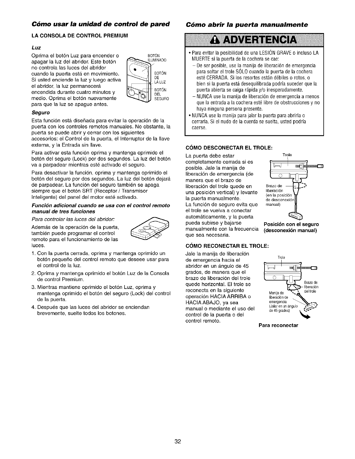
C6mo usar la unidad de control de pared C6mo abrir la puerta manualmente
LA CONSOLA DE CONTROL PREMIUM
Luz
Optima el bot6n Luz para encender o
apagar la luz del abridor. Este bot6n
no controla las luces del abridor
cuando la puerta est,. en movimiento.
Si usted enciende la luz y luego activa
el abridor, la luz permanecerA
encendida durante cuatro minutos y
medio. Oprima el bot6n nuevamente
para que la luz se apague antes.
BOTON
ILUMINADO
DE
LALUZ
BOTON
DEL
SEGURO
Seguro
Esta funci6n est_ disefiada para evitar la operaci6n de la
puerta con los controles remotos manuales. No obstante, la
puerta se puede abrir y cerrar con los siguientes
accesorios: el Control de la puerta, el Interrupter de la Ilave
externa, y la Entrada sin Ilave.
Para activar esta funci6n oprima y mantenga oprimido el
bot6n del seguro (Lock) por dos segundos. La luz del bot6n
va a parpadear mientras este activado el seguro.
Para desactivar la funcion, oprima y mantenga oprimido el
bot6n del seguro por dos segundos. La luz del bot6n dejara
de parpadear. La funcion del seguro tambi6n se apaga
siempre que el bot6n SRT (Receptor /Transmisor
Inteligente) del panel del motor este activado.
Funci6n adicional cuando se usa con el control remoto
manual de tres funciones
Para controlar las luces del abridor:
Adem_.s de la operacion de la puerta,
tambien puede programar el control
remoto para el funcionamiento de las
luces.
1. Con la puerta cerrada, oprima y mantenga oprimido un
bot6n pequefie del control remote que deseee usar para
el control de la luz.
2. Oprima y mantenga oprimido el bot6n Luz de la Consola
de control Premium.
3. Mientras mantiene oprimido el bot6n Luz, oprima y
mantenga oprimido el bot6n del seguro (Lock) de] control
de la puerta.
4. Despues que las luces del abridor se enciendan
brevemente, suelte tedes los botones.
•ParaevitarlaposibilidaddeunaLESIONGRAVEo inclusoLA
MUERTEsi la puertadelacocherasecae:
-Deserposible,usela manijadeliberaci6ndeemergencia
parasoltareltrole SOLOcuandola puertadelacochera
est6CERRADA.Si los resortesest_nd6bileso rotos,o
biensi lapuertaest_desequilibradapodriasucederquela
puertaabiertasecaigardpiday/oinesperadamente.
-NUNOAuselamanijadeliberaci6ndeemergenciaa rnenos
quelaentradaa lacocheraest6libredeobstruccionesy no
hayaningunapersonapresente.
•NUNOAusela rnanijaparajalarla puertaparaabrirlao
terraria.Siel nudodelacuerdase suelta,ustedpodria
caerse.
C(3MO DESCONECTAR EL TROLE:
La puerta debe estar Trole.
-I
completamente cerrada si es
posible. Jale la manija de
liberaci6n de emergencia (de
manera que el brazo de
liberaci6n del trole quede en Brazode ._J
una posici6n vertical) y levante liberaci6n
(en la posici6n
la puerta manualmente, dedesconexi6n
La funci6n de seguro evita que manual)
el trole se vuelva a conectar
automaticamente, y la puerta '_'
pueda subirse y bajarse Posici6n con el seguro
manualmente con la frecuencia (deseonexi6n manual)
que sea necesaria.
C(_MO RECONECTAR EL TROLE:
Jale la manija de liberacion
de emergencia hacia el
abridor en un _.ngulo de 45
grados, de manera que el
brazo de liberaci6n del trole
quede horizontal. El trole se
reconecta en la siguiente
operaci6n HACIA ARRIBA o
HACIA ABAJO, ya sea
manual o mediante el uso del
control de la puerta o del
control remoto.
Trole
erazo de
liberaci6n
Iiberaci6nde gulo_ t
eraergencia .-
(Jalaren un&n
de 45 grados) _ _$'_"
Para reconectar
32
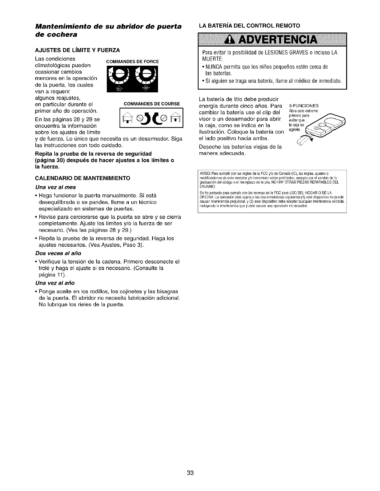
Mantenimiento de su abridor de puerta LA BATERIA DEL CONTROL REMOTO
de cochera
AJUSTES DE LiMITE Y FUERZA
Las condiciones
climatologicas pueden
ocasionar cambios
menores en la operaci6n
de la puerta, los cuales
van a requerir
algunos reajustes,
en particular durante el
primer afio de operaci6n.
En las p_ginas 28 y 29 se
encuentra la informaci6n
sobre los ajustes de limite
COMMANDESDEFORCE
COMMANDES DE COURSE
y de fuerza. Lo L_nicoque necesita es un desarmador. Siga
las instrucciones con todo cuidado.
Repita la prueba de la reversa de seguridad
(p&gina 30) despu_s de hacerajustes a los limites o
la fuerza.
CALENDARIO DE MANTENIMIENTO
Una vez al mes
•Haga funcionar la puerta manualmente. SiestA
desequilibrada o se pandea, flame a un t6cnico
especializado en sistemas de puertas.
•Revise para cerciorarse que la puerta se abre y se cierra
completamente. Ajuste los limites y/o la fuerza de ser
necesario. (Vea las pAginas 28 y 29.)
• Repita la prueba de la reversa de seguridad. Haga los
ajustes necesarios. (Vea Ajustes, Paso 3).
Dos veces al a_o
• Verifique la tensi6n de la cadena. Primero desconecte el
trole y haga el ajuste si es necesario. (Consulte la
p_.gina 11).
Una vez al a_o
• Ponga aceite en los rodillos, los cojinetes y las bisagras
de la puerta. El abridor no necesita lubricaci6n adicional.
No lubrique los rieles de la puerta.
Paraevitar la posibilidad de LESIONESGRAVESo incluso LA
MUERTE:
• NUNCApermita que los nifios pequefios est_n cerca de
las baterias.
• Si alguien se traga una bateria, flame al m6dico de inmediato.
La bateria de litio debe producir
energia durante cinco afios. Para 3-FUNCIONES
cambiar la bateria use el clip del Abraesteextrem0
pr_mer0uePea__para
visor o un desarmador para abrir evitarque
la caja, como se indica en la lacaiase
ilustraci6n. Coloque la bateria con agrle:i_
el lade positivo hacia arriba.
Deseche las baterias viejas de la
manera adeeuada.
AVISO:Palacumplirconlas reglasde laFCCy/odeCanada(IC),las reglas,ajusteso
33
Si tiene algbn problema
1. E! abridor no funciona con el control de la puerta ni con el
control remote:
•),Esta el abridor conectado a la electricidad? Conecte una
lampara a la toma de corriente. Si no se enciende, revise la caja
de fusibles o el cortacircuito. (AIgunas tomas de corriente se
controlan con un interruptor de pared).
_,Ha desactivado todas los seguros de las puertas? Revise las
advertencias de las instrucciones de instalaci6n que aparecen en
Ia pagina 11.
&Hay nieve o hielo acumulado debajo de la puerta? La puerta
puede congelarse y quedarse pegada al piso. EIimine esta
restricci6n.
El resorte de la pueda de cochera puede estar roto. Haga que Io
cambien.
Es posible que las repetidas operaciones hayan disparado el
protector de sobrecarga del motor. Espere 15 minutos y vueiva a
intentar.
2. E! abridor opera con el control remote, pore no funciona con
el control de/a puerta:
• _Esta iluminado el control? Si no es asf, quite el alambre del
timbre de las terminales de la unidad del motor. Ponga en corto
las terminales roja y blanca tocando con un pedazo de alambre
ambas terminales al mismo tiempo. Si el abridor funciona, revise
si hay alguna mala conexi6n en Io alambres del control de la
puerta, un corto bajo Ias grapas, o alg0n alambre roto.
• &Lasconexionesdelcableadosoncorrectas?ReviseelPaso6
de la seccion de Instalacidn en la pagina 18.
3. La puerta funciona con el control de la puerta, pore no
funciona con el control remote:
• _,Esta parpadeando el bot6n de la pueda? Si el modelo de su
abridor tiene la funci6n de seguro (Lock), cerci6rese de que este
apagada.
• Programe el abridor para que coincida con el c6digo deI control
remoto. (Consulte las instrucciones que se encuentran en el
panel del motor). Repita esto con todos los controles remotos.
4. El control remote tiene corto alcance:
• Cambie la ubicaci6n del control remoto en su coche.
• Revise y cerci6rese de que la antena que se encuentra a un lado
o en el panel posterior de la unidad del motor se extienda hacia
abajo completamente.
• Algunas instalaciones pueden tener menor alcance si las puertas
son de metal, tienen aislamiento, o el recubrimiento externo de la
cochera es de metal. (Estuche de extensi6n de antena 41A3504).
5. E! ruido que hace el abridor molesta en las habitaciones de
la casa:
• Si el ruido de la operaci6n del abridor es un problema porque las
habitaciones de la casa esten muy cerca, se puede instalar un
Aislador de la vibracion 41A3263. Este accesorio est_i diseSado
para minimizar la vibraci6n en Ia casa yes f#,cil de instalar.
6. La puerta de la cochera se abre y se cierra per s[ misma:
• Aseg[irese que todos los botones del control remoto esten
apagados.
• Quite el alambre del timbre de las terminales del control de la
puerta y haga funcionar la puerta solamente con el control
remoto. Si esto resuelve el problema, el control de la puerta tiene
alguna falla (cambielo), o hay alg0n corto intermitente en el
alambre entre el control de la pueda y la unidad del motor.
• Limpie la memoria y vuelva a programar todos los controles
remotos.
7. La puerta no hab/e completamente:
•z,Hay algo que este obstruyendo la puerta? _,Esta desequilibrada,
o los resortes est_in rotos? Elimine la obstruccion o repare la
puerta.
• Si la puerta est_i en buenas condiciones pero no abre
completamente, aumente la fuerza hacia arriba. Vea Ajustes,
Paso 2.
•Si la puerta abre pot Io menos cinco pies, es posible que se
tengan que aumentar los Ifmites del recorrido. Una vuelta
equivale a 5 cm (2 pulg.) del recorrido. Vea Ajustes, Paso I.
Repita la prueba de seguddad de reversa despues de terminar
el ajuste.
8. La puerta se detiene pero no cierra completamente:
•Revise los procedimientos de ajuste de los Ifmites del recorrido
que aparecen en la pdtgina 28.
Repita la prueba de seguddad de reversa despues de realizar
cualquier ajuste al largo de! brazo de la puerta, a la fuerza o al Ifmite
hacia abajo.9. La puerta se abre pero no se cierra:
•Si las luces del abridor parpadean, revise el sensor de seguridad de
reversa. Vea la seccion de Instalacidn, Paso 10.
• Si las luces deI abridor no parpadean y se trata de una instalacion
nueva, revise la fuerza hacia abajo. Vea la seccion de Ajuetes,
Paso 2 que aparece en la pagina 29. Si se trata de una instalaci6n
ya existente, yea a continuaci6n.
Repita la prueba de seguddad de reversa despues de terminar
el ajuste.
10. La puerta retrocede sin razSn aparente y las luces del abridor
no parpadean:
• _,Hay algo que este obstruyendo la puerta? Jale la manija de
Iiberacion de emergencia. Opere la puerta manualmente. Si est_i
desequilibrada o se pandea, Ilame a un tecnico especializado en
sistemas de puertas.
• Limpie el piso de la cochera si tiene hielo o nieve en el punto donde
Ia puerta cierra.
• Revise Ajustes, Paso 2 en la pagina 29.
• Si la puerta retrocede a la posici6n completamente cerrada,
disminuya los limites de recorrido (Ajustes, Paso 1).
Repita la prueba de seguddad de reversa despues de hacer los
ajustes a la fuerza o a los Ilmites del recorddo, La necesidad de un
ajuste ocasional de la fuerza y del ffmite es normal Las eondieiones
climatologicas en particular pueden afectar e! recorddo de la puerta,
11. La puerta retrocede sin raz6n aparente y las luces de/abridor
parpadean per cinco segundos despu_s de que retrocede:
• Revise el sensor de reversa de seguridad. Quite cualquier
obstrucci6n o alinee el ojo recepton Vea la seccion de Instalacion,
Paso 10.
12. Las /uces del abridor no se encienden:
•Cambie los focos (de 75 vatios maximo). Use un foco estandar para
puerta de cochera, si el foco se funde.
13. Las luces del abridor no se apagan:
• &Est_i activada la funcion de luz? Si es asi, apaguela.
14. E! abridor necesita la m#xima fuerza para operar la puerta:
• La puerta podria estar desequilibrada, o los resodes poddan
estar rotos. Cierre la puerta y use la manija de liberacion de
emergencia para desconectar el trole. Abra y cierre la pueda
manualmente. Si Ia pueda est_i bien equilibrada se sostiene en
cualquier punto del recorrido con s61o el soporte de sus resortes. Si
esto no ocurre, desconecte el abridor y llama a un tecnico
especializado en sistemas de puertas. No aumenta la fuerza
para operar el abridor.
15. E! motor hace un ruido brevemente pero luego no funciona
• Los resortes de Ia pueda de cochera podrian estar rotos. Vea los
parrafos anteriores.
• Si el probtema se presenta la primera vez que opera el abridor,
puede ser que la pueda este con seguro. Quite el seguro de la
puerta. Si ha quitado la cadena y la ha vuelto a inetalar, el motor
podda estas desfasado. Quite la cadena; corra el ciclo del motor
hasta Ia posici6n hacia abajo. Observe la polea o rueda dentada, si
gira a la derecha, es decir en el sentido de las manecillas del reloj,
y se detiene en la posicion hacia abajo, vuelva a instalar la cadena.
Repita la prueba de seguddad de reversa despues de terminar
el ajuste
16. E! abridor no funciona debido a una falla en el suministro
de energ(a
• Use la manija de liberaci6n de emergencia para desconectar el
trole. La puerta se puede abfir y cerrar manualmente. Cuando se
restaure el suministro de energia, optima el bot6n de control de la
puerta y el trole se vuelve a conectar automaticamente (a menos
que este con seguro). Vea la pagina 32.
• El accesorio Llave de liberaci6n de emergencia (que se usa
solamente en las cocheras que no tienen una puerta de servicio)
desconecta el trole desde afuera de Ia cochera en caso de una falla
en el suministro de energia.
17. Si la cadena se cuelga o se af!oja:
• Es normal que la cadena cuelgue un poco cuando la puerta esta
cerrada. Use la liberaci6n de emergencia para desconectar el trole.
Si la cadena vuelve a su altura normaI cuando el trole esta
desconectado y la puerta retrocede al toparse con un pedazo de
madera de 2.5 cm (1 pulg.), no es necesario efectuar ning0n ajuste.
(Vea la pdtgina 11).
34
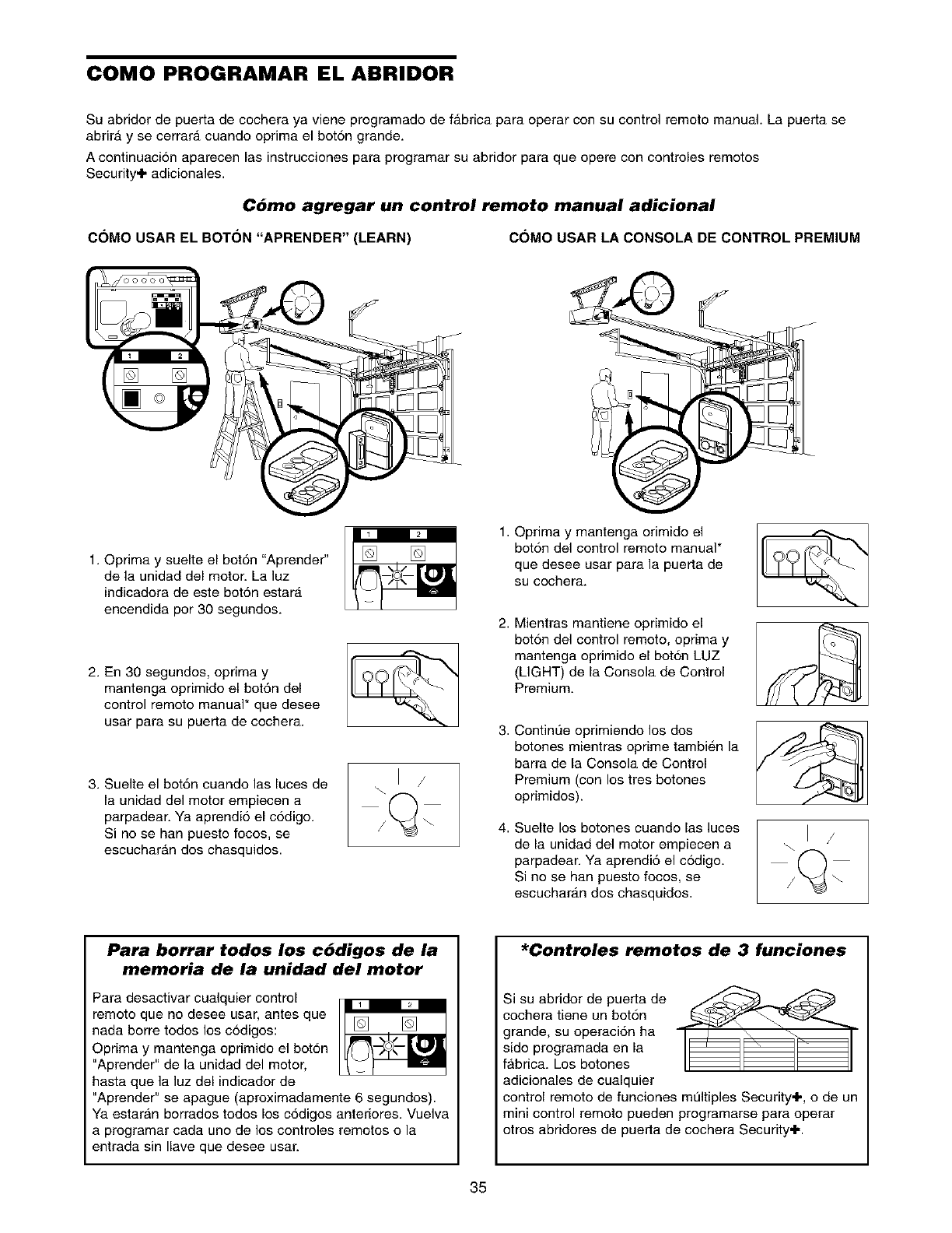
COMO PROGRAMAR EL ABRIDOR
Su abridor de puerta de cochera ya viene programado de fabrica para operar con su control remoto manual. La puerta se
abrirA y se cerrara cuando oprima el bot6n grande.
A continuaci6n aparecen las instrucciones para programar su abridor para que opere con controles remotos
Security+ adicionales.
Cbmo agregar un control remoto manual adicional
C(_MO USAR EL BOT(_N "APRENDER" (LEARN) C(_MO USAR LA CONSOLA DE CONTROL PREMIUM
1. Oprima y suelte el bot6n "Aprender"
de la unidad del motor. La luz
indicadora de este bot6n estara
encendida por 30 segundos.
2. En 30 segundos, optima y
mantenga oprimido el bot6n del
control remote manual* que desee
usar para su puerta de cochera.
3. Suelte el bot6n cuando las luces de
la unidad del motor empiecen a
parpadear. Ya aprendi6 el c6digo.
Si no se ban puesto focos, se
escucharAn dos chasquidos.
\1 /
1. Oprima y mantenga orimido el
bot6n del control remoto manual*
que desee usar para la puerta de
su cochera.
2. Mientras mantiene oprimido el
bot6n del control remoto, oprima y
mantenga oprimido el bot6n LUZ
(LIGHT) de la Consola de Control
Premium.
3. ContinL'le oprimiendo los dos
botones mientras oprime tambi_,n la
barra de la Consola de Control
Premium (con los tres botones
oprimidos).
4. Suelte los botones cuando las luces
de la unidad del motor empiecen a
parpadear. Ya aprendi6 el c6digo.
Si no se ban puesto focos, se
escucharan dos chasquidos.
\1 /
Para borrar todos los cddigos de la
memoria de la unidad del motor
Para desactivar cualquier control
remoto que no desee usar, antes que
nada borre todos los c6digos:
Oprima y mantenga oprimido el bot6n
"Aprender" de la unidad del motor,
hasta que la luz del indicador de
"Aprender" se apague (aproximadamente 6 segundos).
Ya estaran borrados todos los c6digos anteriores. Vuelva
a programar cada uno de los controles remotos o la
entrada sin Ilave que desee usar.
*Controles remotos de 3 funciones
Si su abridor de puerta de
cochera tiene un bot6n
grande, su operaci6n ha
sido programada en la
fAbrica. Los botones
adicionales de cualquier
control remoto de funciones multiples Security+, o de un
mini control remoto pueden programarse para operar
otros abridores de puerta de cochera Security+.
35
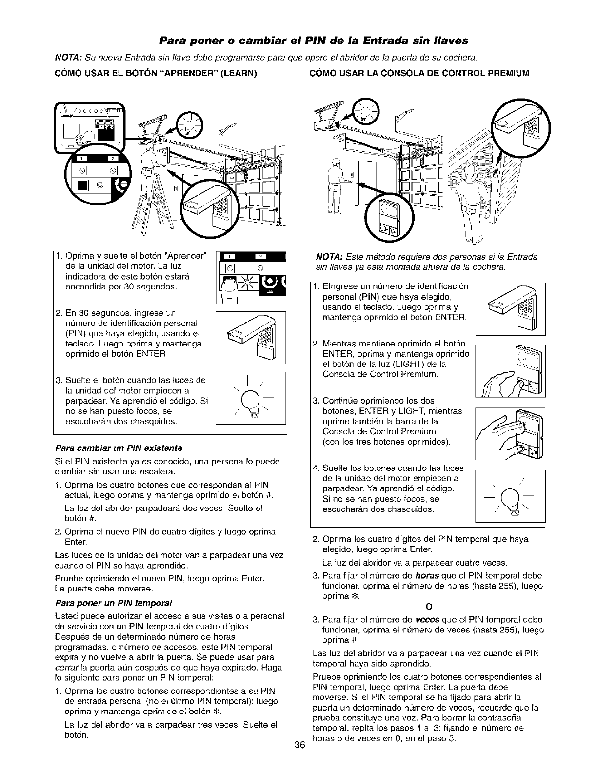
Para poner o cambiar el PIN de la Entrada sin Ilaves
NOTA: Su nueva Entrada sin/lave debe programarse para que opere el abridor de la puerta de su cochera.
COMO USAR EL BOT(_N "APRENDER" (LEARN) C(_MOUSAR LA CONSOLA DE CONTROL PREMIUM
1. Oprima y suelte el bot6n "Aprender"
de la unidad del motor. La luz
indicadora de este bot6n estarA
encendida por 30 segundos.
i En 30 segundos, ingrese un
numero de identificaci6n personal
(PIN) que haya elegido, usando el
teclado. Luego oprima y mantenga
oprimido el bot6n ENTER.
Suelte el bot6n cuando las luces de
la unidad del motor empiecen a
parpadear. Ya aprendi6 el c6digo. Si
no se ban puesto focos, se
escucharan dos chasquidos.
\1 /
Para cambiar un PIN existente
Si el PIN existente ya es conocido, una persona Io puede
cambiar sin usar una escalera.
1. Oprima los cuatro botones que correspondan al PIN
actual, luego oprima y mantenga oprimido el bot6n #.
La luz del abridor parpadeara dos veces. Suelte el
bot6n #.
2. Oprima el nuevo PIN de cuatro dfgitos y luego oprima
Enter.
Las luces de la unidad del motor van a parpadear una vez
cuando el PIN se haya aprendido.
Pruebe oprimiendo el nuevo PIN, luego oprima Enter.
La puerta debe moverse.
Para poner un PIN temporal
Usted puede autorizar el acceso a sus visitas o a personal
de servicio con un PIN temporal de cuatro dfgitos.
Despues de un determinado n=3merode horas
programadas, o nt_mero de accesos, este PIN temporal
expira y no vuelve a abrir la puerta. Se puede usar para
cerrarla puerta alan despu_,s de que haya expirado. Haga
Io siguiente para porter un PIN temporal:
1. Optima los cuatro botones correspondientes a su PIN
de entrada personal (no el L_ltimo PiN temporal); luego
oprima y mantenga oprimido el bot6n ¢-.
La luz del abridor va a parpadear tres veces. Suelte el
bot6n.
36
NOTA: Este metodo requiere dos personas si la Entrada
sin/laves ya esta montada afuera de la cochera.
1. Elngrese un nL_mero de identificaci6n
personal (PIN) que haya elegido,
usando el teclado. Luego oprima y
mantenga opdmido el bot6n ENTER.
2. Mientras mantiene oprimido el bot6n
ENTER, oprima y mantenga oprimido
el bot6n de la luz (LIGHT) de la
Consola de Control Premium.
3. ContinL_e oprimiendo los dos
botones, ENTER y LIGHT, mientras
oprime tambi6n la barra de la
Consola de Control Premium
(con los tres botones oprimidos).
4. Suelte los botones cuando las luces
de la unidad del motor empiecen a
parpadear. Ya aprendi6 el c6digo.
Si no se ban puesto focos, se
escucharan dos chasquidos.
\1 /
2. Oprima los cuatro dfgitos del PIN temporal que haya
elegido, luego oprima Enter.
La luz del abridor va a parpadear cuatro veces.
3. Para fijar el nt_mero de horas que el PIN temporal debe
funcionar, oprima el n0mero de horas (hasta 255), luego
oprima¢. O
3. Para fijar el nt_mero de veces que el PIN temporal debe
funcionar, oprima el n0mero de veces (hasta 255), luego
optima #.
Las luz del abridor va a parpadear una vez cuando el PIN
temporal haya sido aprendido.
Pruebe opdmiendo los cuatro botones correspondientes al
PIN temporal, luego optima Enter. La puerta debe
moverse. Si el PIN temporal se ha fijado para abrir la
puerta un determinado nL_mero de veces, recuerde que la
prueba constituye una vez. Para borrar la contraseSa
temporal, repita los pasos 1 al 3; fijando el numero de
horas o de veces en 0, en el paso 3.
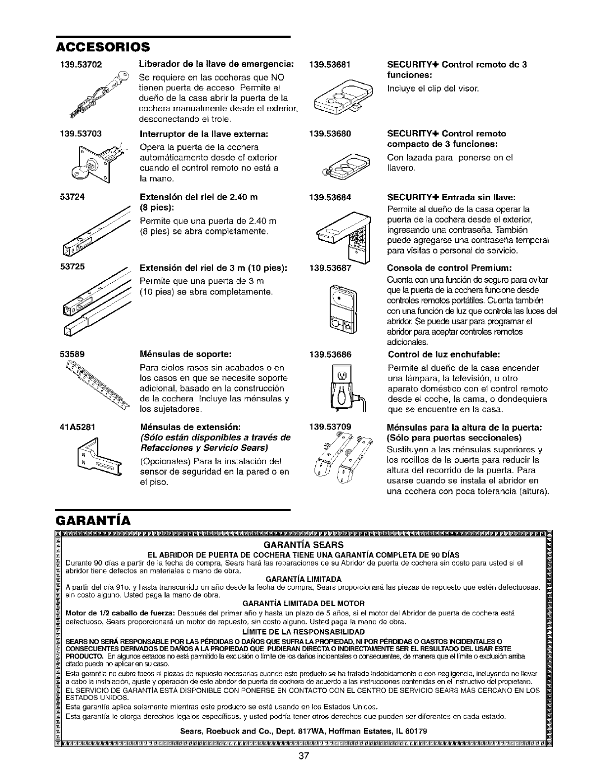
ACCESORIOS
139.53702 Liberador de la Ilave de emergencia:
Se requiere en las cocheras que NO
tienen puerta de acoeso. Permite al
duefio de la casa abrir la puerta de la
cochera manualmente desde el exterior,
desconectando el trole.
139.53703 Interruptor de la Ilave externa:
Opera la puerta de la cochera
autom_ticamente desde el exterior
cuando el control remoto no esta a
la mano.
53724 Extensi6n del riel de 2.40 m
(8 pies):
Perrnite que una puerta de 2.40 m
(8 pies) se abra completamente.
53725 Extensi6n del riel de 3 m (10 pies):
Permite que una puerta de 3 m
(10 pies) se abra completamente.
53589
41A5281
M_nsulas de soporte:
139.53681
139.53680
139.53684
139.53687
139.53686
Para cielos rasos sin acabados o en
los cases en que se necesite soporte
adicional, basado en la construcoi6n
de la cochera. Incluye las mensulas y
los sujetadores.
Mdnsulas de extensi6n:
($61o est_n disponibles a travds de
Refacciones y Servicio Sears)
(Opcionales) Para la instalaelon del
sensor de seguridad en la pared o en
el piso.
139.53709
SECURITY+ Control remoto de 3
funciones:
Incluye el clip del visor.
SECURITY+ Control remoto
compacto de 3 funciones:
Con lazada para ponerse en el
Ilavero.
SECURITY+ Entrada sin Ilave:
Perrelte al duefio de la casa operar la
puerta de la cochera desde el exterior,
ingresando una contrasefia. Tambien
puede agregarse una contrasefia temporal
para visitas o personal de servicio.
Consola de control Premium:
Cuenta con una funcide de seguro para evitar
que la puerta de la ccohera funcione desde
contreles remotos port,tiles. Cuenta tambien
con una funcion de luz que contrela las luces del
abride_ Se puede usar para programar el
abrider para aceptar contreles remotos
adicioneles.
Control de luz enchufable:
Permite al duefio de la casa encender
una I_.mpara, la television, u otro
aparato dom_,stico con el control remoto
desde el coche, la cama, o dondequiera
que se encuentre en la casa.
M_nsulas para la altura de la puerta:
($61o para puertas seccionales)
Sustituyen a las m6nsulas superiores y
los rodillos de la puerta para reducir la
altura del recorrido de la puerta. Para
usarse cuando se instala el abridor en
una cochera con poca tolerancia (altura).
GARANTJA
GARANTIA SEARS
ELABRIDORDEPUERTADECOCHERATIENE UNAGARANTiACOMPLETADE90 DiAS
Durante90dias a partir de ta fecha de compra,Sears har_las reparaciones de su Abddor depuerta de cocherasin costo paraustedsi el
abridordene defectosen matedaleso manodeobra. GARANTiALIMITADA
A partirdeldia 91o. y hastatranscurddouna_o desde la fechade cornpra,Searsproporcionar_las piezasde repuestoque estendefectuosas,
sin costoalguno.Usted pagala manode obra. GARANTIALIMITADADELMOTOR
Motorde 112caballodefuerza: Despuesdel primerai_oy hasta un plazode5 a_os,si el motor del Abridorde puertade cocheraesta
defectuoso,Sears proporcionar_un motorde repuesto,sincosto alguno.Ustedpaga ta manodeobra.
LiMITEDELA RESPONSABILIDAD
SEARS NO SERA RESPONSABLE POR LAS P_:RDIDAS O DAI_OS QUE SUFRA LA PROPIEDAD, NI POR PERDIDAS O GASTOS INClDENTALES O
CONSECLIENTES DERIVADOS DE DANOS A LA PROPIEDAD QUE PUDIERAN DIRECTA O INDIRECTAM ENTE SER EL RESULTADO DEL LISAR ESTE
PRODUCTO.EnalgunosestadosnoestApermitidolaexdusiSno {imitedelosda_asincidertalesoconsecuentes,demaneraqueelIimiteo exctusi6nardba
citadopuedenoaplicarensucaso.
Esta garandenocubrefocosnipiezas de repuesto necesariascuandoesteproducto se hatratadoindebidamenteocon negligencia, incluyendonollevar
a cabola instalacide, ajuste y operacide deesteabddorde puededecocheradeacuerdoalas instruccionescontenidasenel instructivodelpropietade.
ELSERVIClODEGARANTiA EST', DiSPONIBLECONPONERSEENCONTACTOCONELCENTRODESERVIClOSEARSM,_S CERCANOENLOS
ESTADOSUNIDOS.
Esta garantia apiica solamentemientrasesteproducto se est_usandoen los EstadosUnidos.
Esta garantia le otorga derechos legales especificos, y ustedpodria tenerotrosderechosque pueden ser diferentesen cada estado.
Sears, Roebuck and Co., Dept. 817WA, Hoffman Estates, IL 60179
37
Your Home
For repair-in your home-of all major brand appliances,
lawn and garden equipment, or heating and cooling systems,
no matter who made it, no matter who sold it!
For the replacement parts, accessories and
owner's manuals that you need to do-it-yourself.
For Sears professional installation of home appliances
and items like garage door openers and water heaters.
1-800-4-MY-HOME ®(1-800-469-4663)
Call anytime, day or night (U.S.A. and Canada)
www.sears.com www.sears.ca
Our Home
For repair of carry-in items like vacuums, lawn equipment,
and electronics, call or go on-line for the location of your nearest
Sears Parts & Repair Center.
1-800-488-1222
Call anytime, day or night (U.S.A. only)
www.sears.com
To purchase a protection agreement (U.S.A.)
or maintenance agreement (Canada) on a product serviced by Sears:
1-800-827-6655 (U.S.A.) 1-800-361-6665 (Canada)
Para pedir servicio de reparaci6n
a domicilio, y para ordenar piezas:
1-888-SU-HOGAR SM
(1-888-784-6427)
Au Canada pour service en fran£ais:
1-800-LE-FOYER Mc
(1-800-533-6937)
www.sears.ca
114A2631C
® Registered Trademark /TMTrademark /M Service Mark of Sears, Roebuck and Co.
® Marca Registrada /TMMarca de F#,bdca /s_ Marca de Servic{o de Sears, Roebuck and Co.
'_° Marque de commerce /_° Marque d_pos_e de Sears, Roebuck and Co. © 2003 Sears, Roebuck and Co.
Printed in Mexico
