Sears 143 804062 Users Manual
536885410 536885410 CRAFTSMAN SNOW THROWER - Manuals and Guides L0810227 View the owners manual for your CRAFTSMAN SNOW THROWER #536885410. Home:Lawn & Garden Parts:Craftsman Parts:Craftsman SNOW THROWER Manual
CRAFTSMAN Snowthrower, Gas Manual L0810227 CRAFTSMAN Snowthrower, Gas Owner's Manual, CRAFTSMAN Snowthrower, Gas installation guides
536.885410 L0810227
143.804062 to the manual 8dd62955-836c-412f-8916-f007c8712d59
2015-02-05
: Sears Sears-143-804062-Users-Manual-399491 sears-143-804062-users-manual-399491 sears pdf
Open the PDF directly: View PDF ![]() .
.
Page Count: 38
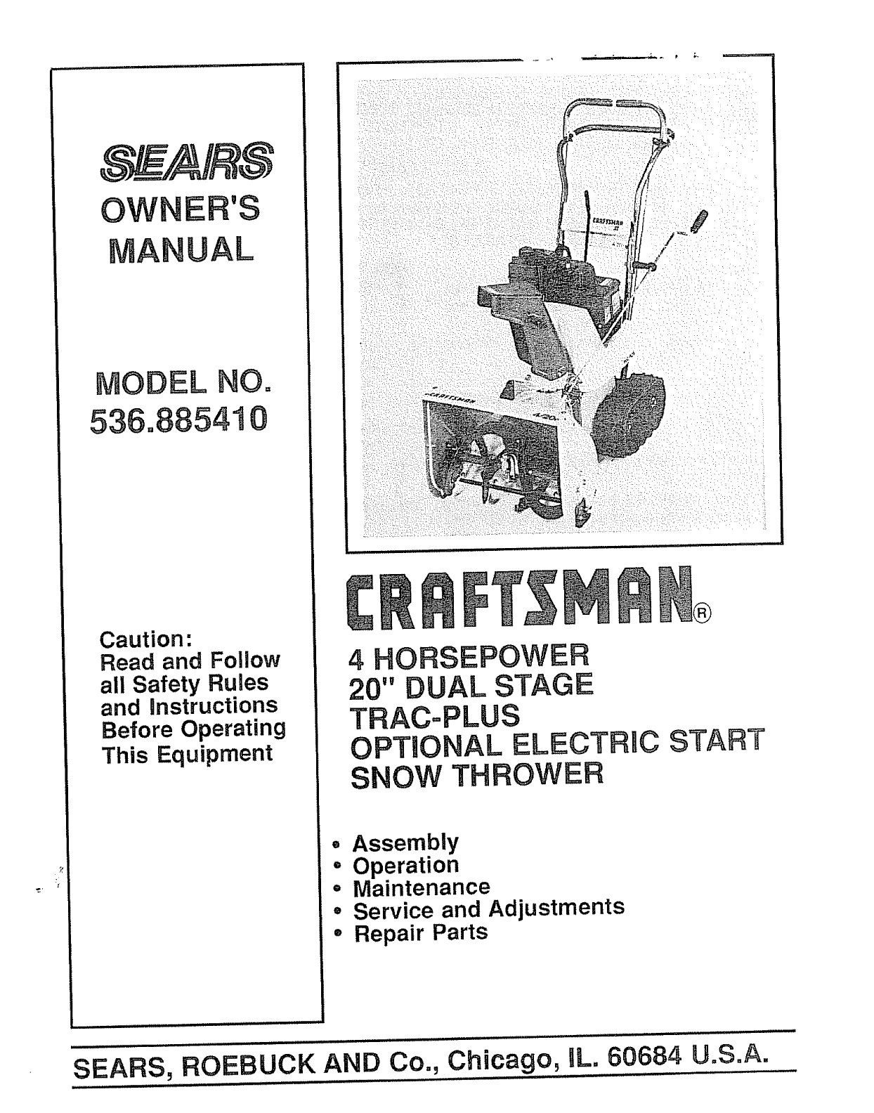
OWNE 'S
UAL
MODEL NO=
536.885410
Caution-.
Read and Follow
all Safety Rules
and instructions
Before Operating
This Equipment
4 HORSEPOWER
20" DUAL STAGE
TRAC=PLUS
OPTIONAL ELECTRBC START
SNOW THROWER
•Assembly
oOperation
= Maintenance
° Service and Adjustments
- Repair Parts
SEARS, ROEBUCK AND Co., Chicago, aL. 60684 U.SoA.
SAFETY RULES
CAUTION: ALWAYS DISCONNECT SPARK PLUG WIRE AND A
PLACE WIRE WHERE IT CANNOT CONTACT SPARK PLUG TO &
PREVENT ACCIDENTAL STARTING WHEN SETTING-UP,
TRANSPORTING, ADJUSTING OR MAKING REPAIRS.
IMPORTANT
SAFETY STANDARDS REQUIRE OPERATOR PRESENCE CONTROLS TO MINIMIZE
THE RISK OF INJURY. YOUR SNOW THROWER IS EQUIPPED WITH SUCH CONTROLS.
DO NOT ATTEMPT TO DEFEAT THE FUNCTION OF THE OPERATOR PRESENCE
CONTROL UNDER ANY CIRCUMSTANCES,
BEFORE USE
® Read the owner's manual carefully. Be thor-
oughly familiar with the controls and the proper
use of the snow thrower. Know how to stop the
snow thrower and disengage the controls
quickly.
® Do not operate the snow thrower without wear-
ing adequate winter outer garments. Wear
footwear that will improve footing on slippery
surfaces°
® Keep the area of operation clear of all persons,
particularly small children, and pets.
e Thoroughly inspect the area where the snow
thrower is to be used and remove all doormats,
sleds, boards, wires, and other foreign objects.
e Use extension cords and receptacles as speci-
fied by the manufacturer for all snow throwers
with electric drive motors or electric starting
motors°
® Use only attachments and accessories ap-
proved by the manufacturer of the snow thrower
(such as tire chains, electric start kits, etco)
e Never operate the snow thrower without good
visibility or light, Always be sure of your footing,
and keep a firm hold on the handles, Walk;
never run.
e This snow thrower is for use on sidewalks,
driveways, and other ground level surfaces.
CAUTION should be exercised while using on
steep sloping surfaces. DO NOT USE SNOW
THROWER ON SURFACES ABOVE
GROUND LEVEL such as reofs of residences,
garages, porches or other such structures or
buildings.
= Check shear bolts and other bolts at frequent
intervals for proper tightness to be sure the
snow thrower is in safe working condition.
e Disengage all clutches and shift into neutral
before starting the engine
® Adjust the snow.thrower height to clear gravel
or crushed rock surface.
® Let engine and snow thrower adjust to outdoor
temperatures before starting to Clear snow.
FUEL .SAFETY
eHandle fuel with care; it is highly flammable.
e Use an approved fuel container.
® Check fuel supply before each use, allowing
space for expansion as the heat of the engine
and/or sun can cause fuel to expand,
® Fill fuel tank outdoors with extreme care. Never
fill fuel tank indoors.
® Replace fuel tank cap securely and wipe up
spilled fuel,
e Never remove fuel tank cap or add fuel to a
runningengine or hot engine_
® Never store fuel or snow thrower with fuel in the
tank inside of a building where fumes may
reach an open flame or spark.
OPERATING SAFETY
® Never allow children or young teenagers to
operate the snow thrower and keep them away
while it is operating. Never allow adults to
operate the snow thrower without proper in-
struction. Do not carry passengers.
® Always wear safety glasses or eye shields
during operation orwhile performing an adjust-
ment or repair to protect eyes from foreign
objects that may be thrown from the snow
thrower.
® Exercise extreme caution when operating on
or crossing gravel drives, walks, or roads, Stay
alert for hidden hazards or traffic°
o Do not put hands or feet near or under rotating
parts. Keep clear of the discharge opening at
all times.
e Exercise caution to avoid slipping or falling, es-
pecially when operating in reverse.
® Do not clear snow across the face of slopes.
Exercise caution when changing direction on
slopes. Do not attempt to clear steep slopes,
® Never operate the snowthrower without proper
guards, plates or other safety protective de-
vices in place.
SAFETY RU LES
e Never operate the snow thrower near glass en-
closures, automobiles, window wells, drop-
offs, and the like without proper adjustment of
the snow discharge angle,, Keep children and
pets away.
® Never operate the snow thrower at high trans-
port speeds on slippery surfaces,. Look behind
and use care when backing.
e Never direct discharge at bystanders or allow
anyone in front of the snow throwers.
o Do not run the engine indoors, except when
starting the engine and for transporting the
snow thrower in or out of the building. Open the
outside doors; exhaust fumes are dangerous
(containing CARBON MONOXIDE, an ODOR-
LESS and DEADLY GAS)_
Take all possible precautions when leaving the
snow thrower unattended., Disengage the
auger!impeller, shift to neutral, stop engine,
and remove key,.
® Do not overload the machine capacity by at-
tempting to clear snow at too fast a rate.,
SAFE STORAGE
e Always referto owner's manual instructions for
important details if the snow thrower is to be
stored for an extended period,
e Disengage power to the auger/impeller when
snow thrower is transported or not in use_
o Never store the snow thrower with fuel in the
fuel tank inside a building where ignition sources
are present such as hot water and space
heaters, clothes dryers, and the like.. A_low the
engine to cool before storing in any enclosure.
REPAIRtADJUSTMENTS SAFETY
e After striking a foreign object, stop the engine
(motor), remove the wire from the spark plug,
disconnect the cord on electric motors, thor-
oughly inspect the snow thrower for any dam-
age, and repair the damage before restarting
and operating the snow thrower°
o If the snow thrower should start to vibrate
abnormally, stop the engine (motor) and check
immediately for the causer Vibration is gener-
ally a warning of trouble_.
® Stop the engine (motor) whenever you leave
the operating position, before unclogging the
auger/impeller housing or discharge guide,
and when making any repairs, adjustments, or
inspections_
o When cleaning, repairing, or inspecting, make
certain the auger/impeller and all moving parts
have stopped° Disconnect the spark plug wire
and keep the wire away from the ptug to
prevent accidental starting.
o Never attempt to make any adjustments while
the engine is running (except when specifically
recommended by manufacturer).
o Maintain or replace safety and instruction
labels, as necessary.
® Run the snow thrower a few minutes after
throwing snow to prevent freeze-up of the
auger/impeller,.
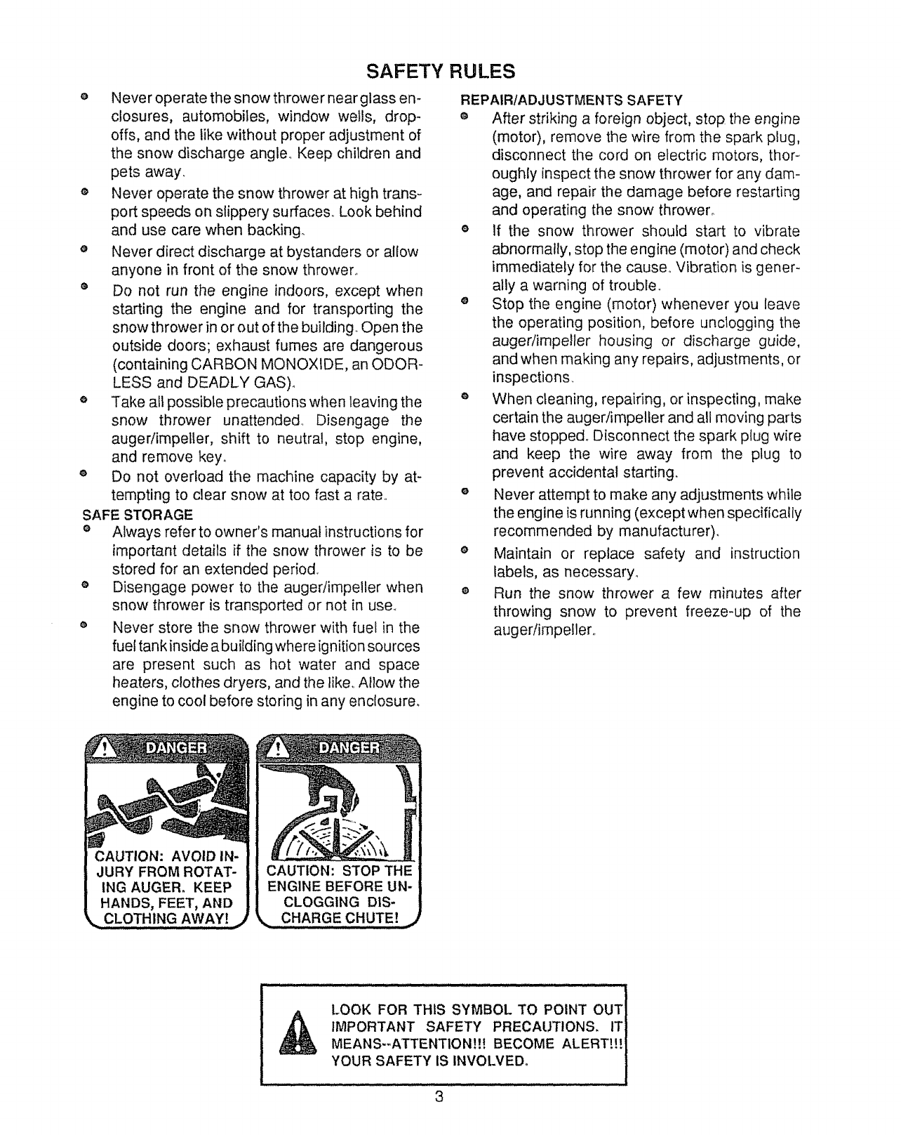
CAUTION: AVOID IN-
JURY FROM ROTAT-
ING AUGER. KEEP
HANDS, FEET, AND
LOOK FOR THIS SYMBOL TO POINT OUT
IMPORTANT SAFETY PRECAUTIONS. IT]
MEANS--ATTENTION!!! BECOME ALERTt!! i
YOUR SAFETY IS INVOLVED.
3
CONGRATULATIONS on your purchase of a Sears
Craftsman Snow Thrower.. It has been designed, engi-
neered and manufactured to give you the best possible
dependability and performance.
Should you experience any problem you cannot easily
remedy, please contact your nearest Sears Service Cen-
tedDepartment. We have competent, well-trained tech-
nicians and the proper tools to service or' repair this unit..
Please read and retain this manual.. The instructions will
enable you to assemble and maintain your snow thrower
properly.. Always observe the "SAFETY RULES/'
MODEL
NUMBER 536.885410
SERIAL
NUMBER
DATE OF
PURCHASE
THE MODEL AND SERIAL NUMBERS WILL BE
FOUND ON A DECAL ATTACHED TO THE REAR
OF THE SNOW THROWER HOUSING
YOU SHOULD RECORD BOTH SERIAL NUMBER
AND DATE OF PURCHASE AND KEEP IN ASAFE
PLACE FOR FUTURE REFERENCE..
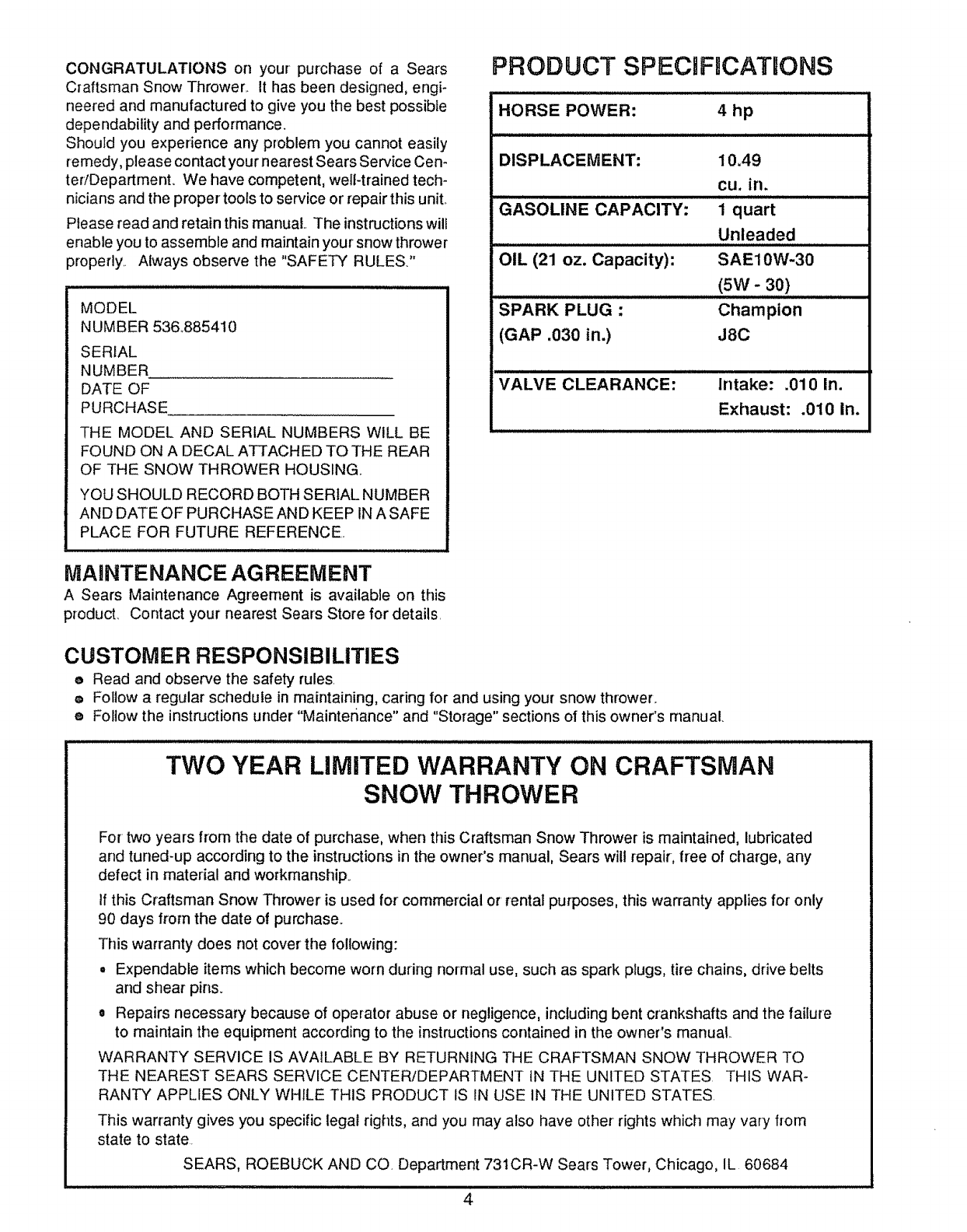
PRODUCT SPECiFmCATIONS
HORSE POWER: 4 hp
DISPLACEMENT:
GASOLINE CAPACITY:
OIL (21 oz. Capacity):
SPARK PLUG -
(GAP .030 in.)
10A9
cu. in.
1quart
Unleaded
SAE10W-30
(5W - 30)
Champion
J8C
VALVE CLEARANCE: Intake: .010 In.
Exhaust: .010 In.
MAINTENANCE AGREEMENT
A Sears Maintenance Agreement is available on this
producL Contact your nearest Sears Store for details,
CUSTOMER RESPONSIBILITIES
eRead and observe the safety rules
o Follow a regular schedule in maintaining, caring for and using your snow thrower.
eFollow the instructions under "Maintenance" and "Storage" sections of this owner's manual.
TWO YEAR LIMITED WARRANTY ON CRAFTSMAN
SNOW THROWER
For two years from the date of purchase, when this Craftsman Snow Thrower is maintained, lubricated
and tuned-up according to the instructions in the owner's manual, Sears wilt repair, free of charge, any
defect in material and workmanship.
If this Craftsman Snow Thrower is used for commercial or rental purposes, this warranty applies for only
90 days from the date of purchase.
This warranty does not cover' the following:
• Expendable items which become worn during normal use, such as spark plugs, tire chains, drive belts
and shear pins.
oRepairs necessary because of operator abuse or negligence, including bent crankshafts and the failure
to maintain the equipment according to the instructions contained in the owner's manual
WARRANTY SERVICE IS AVAILABLE BY RETURNING THE CRAFTSMAN SNOW THROWER TO
THE NEAREST SEARS SERVICE CENTER/DEPARTMENT IN THE UNITED STATES THIS WAR-
RANTY APPLIES ONLY WHILE THIS PRODUCT IS IN USE IN THE UNITED STATES.
This warranty gives you specific legal rights, and you may also have other rights which may vary from
state to state.
SEARS, ROEBUCK AND CO. Department 731CR-W Sears Tower, Chicago, IL 60684
4
TABLE OF CONTENTS
SAFETY RULES ...................................................2,3
PRODUCT SPECIFICATIONS ..............................4
CUSTOMER RESPONSIBILITIES ................. 4
WARRANTY .............................................................4
TABLE OF CONTENTS ...........................................5
INDEX .................................................................... 5
ASSEMBLY ....................................................... 6-8
OPERATION ................................................... 9-t3
MAINTENANCE ...............................................14-15
SERVICE AND ADJUSTMENTS ..............16-22
STORAGE .................................................................23
SERVICE RECOMMENDATIONS ..................24
TROUBLE SHOOTING .........................................25
REPAIR PARTS (SNOWTHROWER) ....26-33
REPAIR PARTS (ENGINE) ....................... 34-37
PARTS ORDERINGISE RVlCE ..... Back Cover
iNDEX
A
Adjustment:
Auger ..............................................................17
Belt ..................................................................t7
Belt Guides ...................................................tg
Cables ...............................................................17
Carburetor .............................................22
Friction Wheel ..........................................t 9
Chute Crank .............................................16
Scraper Bar .................................................16
Spark Plug ...............................................22
Track ..............................................................21
Traction and Auger ....................................17
Assembly:
Crank Assembly ..............................................8
Skid Height Adjustment ..................7, 16
Unpacking ........................................................7
B
Belts:
Adjust Belts ....................................................t7
Belt Guide Adjustment ..........................19
Belt Maintenance .............14, 17, 18, t9
Replace Belts ......................................t8, 19
C
Cables, Clutch ........................................... 7, 9
Carburetor: .......................................22, 23
Chain ...................................................................14
Choke ....................................................9, 1O, 12
Clutch, Levers ..........................................9, t0
Controls:
Engine .............................................9, I0, 12
Snow Thrower ........................9, 10, t 1, t3
Crank:
Adjusting Rod .......................................8, 16
Assembly ........................................................8
Operation .....................................................10
Customer Responsibilities .........................4
D
Drive, Auger ...................................................10
Drive, Traction .........................................10
Deflector, Chute ..........................................t0
E
Engine:
Control .................................................9, 10, t2
Oil Cap .................................................11, t5
Oil Change .............................................16
Oil Level ...........................................11,15
0il Type ...........................................4, 1!, 15
Speed Governor ....................................22
Starting the Engine .............................12
Storage ......................................................23
F
Fuel, Type .................................................4, 12
Fuel, Storage .........................................!2, 24
Friction Wheel:
Adjustment .....................................................I g
Replacement ...............................................20
G
Gears:
Auger Gear Box ...................................14
Hex Shaft ...............................................I4
H
Handle, Upper and Lower ............................7
Height Adjust Skids ..................................7, 16
Hex Shaft ......................................................14
I
Ignition, Key ....................................I0, 11, 12
index ...................................................................5
L
Levers:
Auger Drive Clutch ...........................9, 10
Choke ...............................................9, 1O, 12
Shift Rod Lever ...................................9, 10
Throttle Control ......................9, 10, 12
Traction Drive Clutch .......................9, t 0
Lubrication:
Auger Gear Box ..................................14
Auger Shaft ...................................................14
Chain and Sprockets ................................14
Chart ...........................................................24
Engine ...............................................11, 15
Hex Shaft and Gears ..................!4, 15
Weight Transfer System ......................14
M
Maintenance:
Agreement ............................................4
Auger Gear Box .......................................t4
Auger Shaft ........................................14
Chain and sprockets ..........................14
Engine ....................................................!5
General Recommendations .................14
Hex Shaft and Gears .............................14
Weight Transfer System ......................t4
O
Oil:
Engine ...........................................4, 11, 15
Extreme Cold Weather ................I1, 1'3
Storage ...........................................................23
Type ...............................................4, 11, t5
Operation:
Engine Controls .........................9, 10, t2
Operating Snow Thrower. 10, t 1, 13
Operating Tips ..........................................13
Starting the Engine ...........................12, 13
Snow Thrower Controls ...........9-11, 13
Weight Transfer System ............... t I
P
Parts ............................................... 26-39
Primer Button .......................... 9, !0, 12
R
Repair/Replacement Parts .............26-39
Recoil Starter ...........................................12
Replacements:
Auger Shear Bolt ................................2I
Belts ....................................................17, !8
Friction Wheel ...............................19 20
S
Safety Rules ..................................................2, 3
Service and Adjustments:
Auger Housing Height ........................16
Auger Shear Bolt ................................21
Belts ................................................!7, 18
Belt Guide ...........................................!9
Belt Replacements ....................... 18
Cable .................................................. 17
Carburetor ........................................ 22
Chute Crank ................................... ! 6
Friction Wheel ............................. t9, 20
Spark Plug ...................................... 22
Track ........................................................21
Service Recommendations .............. 24
Spark Plug ............................ 4, 15, 22
Specifications ..........................................4
Speed Governor .....................................22
Starting the Engine ...............................12
Stopping the Engine ........................t0, 12
Stopping the Snow Thrower ................10
Shipping Carton ..................................6, 7
Skid Height .........................................7, t6
Shift Rod Lever ............................ 9, 10
Shear Bolts .................................................21
Storage .....................................................23
T
Table of Contents ................................ 5
Trouble Shooting Chart .................... 25
Tools for Assembly .............................. 6
Traction Drive Belt ...................... t7, 18
Track Adjustment .............................. 2t
W
Warranty ............................................... 4
Weight Trans{er System ................ 9, 11
5
ii ............... ASSE L¥
THIS SNOW THROWER iS EQUIPPED WITH "TRAC-PLUS" AND ONLY
MOVES EFFECTIVELY WHEN ENGnNE iS RUNNING
if your snow thrower must be moved without the aid of the engine, it will be easier' to pull the snow thrower' back-
ward by the handles, rather than pushing°
On start up, the track drive system may be tight and wilt loosen up as the snow thrower is used. After first use,
check the track for tension and adjust if necessary.. See the Track Adjustment paragraph in the Service and Adjust-
ments section of this manual, Check track adjustment and fasteners regularly.
CONTENTS OF SHIPPING CARTON TOOLS REQUnRED FOR ASSEMBLY
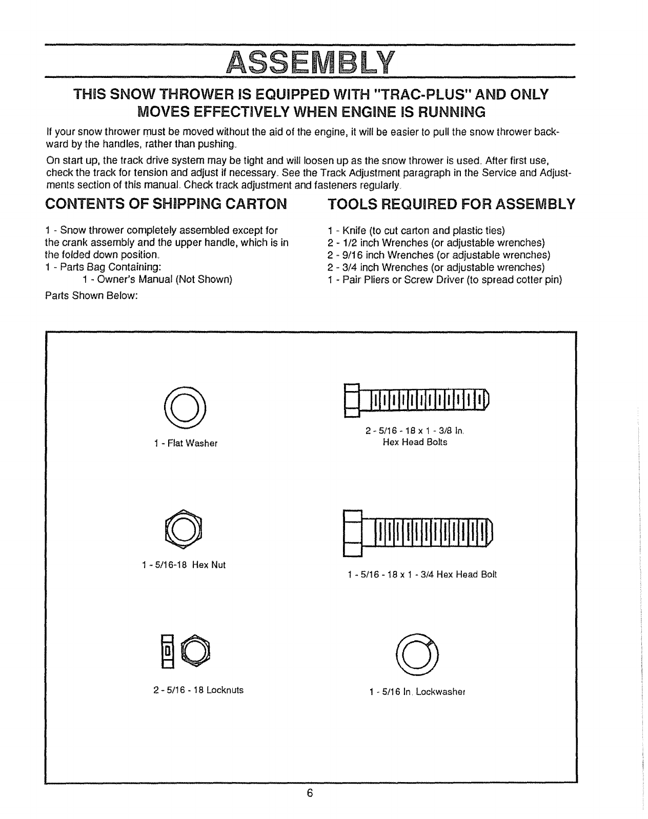
1-Snow thrower completely assembled except for
the crank assembly and the upper handle, which is in
the folded down position°
1 - Parts Bag Containing:
1 - Owner's Manual (Not Shown)
Parts Shown Below:
1 - Knife (to cut carton and plastic ties)
2 - 1/2 inch Wrenches (or adjustable wrenches)
2 - 9/16 inch Wrenches (or adjustable wrenches)
2 - 3/4 inch Wrenches (or adjustable wrenches)
t - Pair' Pliers or Screw Driver (to spread cotter pin)
G
I - Fiat Washer
iiIili!iIiiiIflmlilq_
2- 5/16- 18 x 1 - 3/8 In.
Hex Head Bolts
O
1 -5/16-18 Hex Nut
2 - 5/! 6 - 18 Locknuts
O
1 - 5/16 In. Lockwasher
ASS L¥
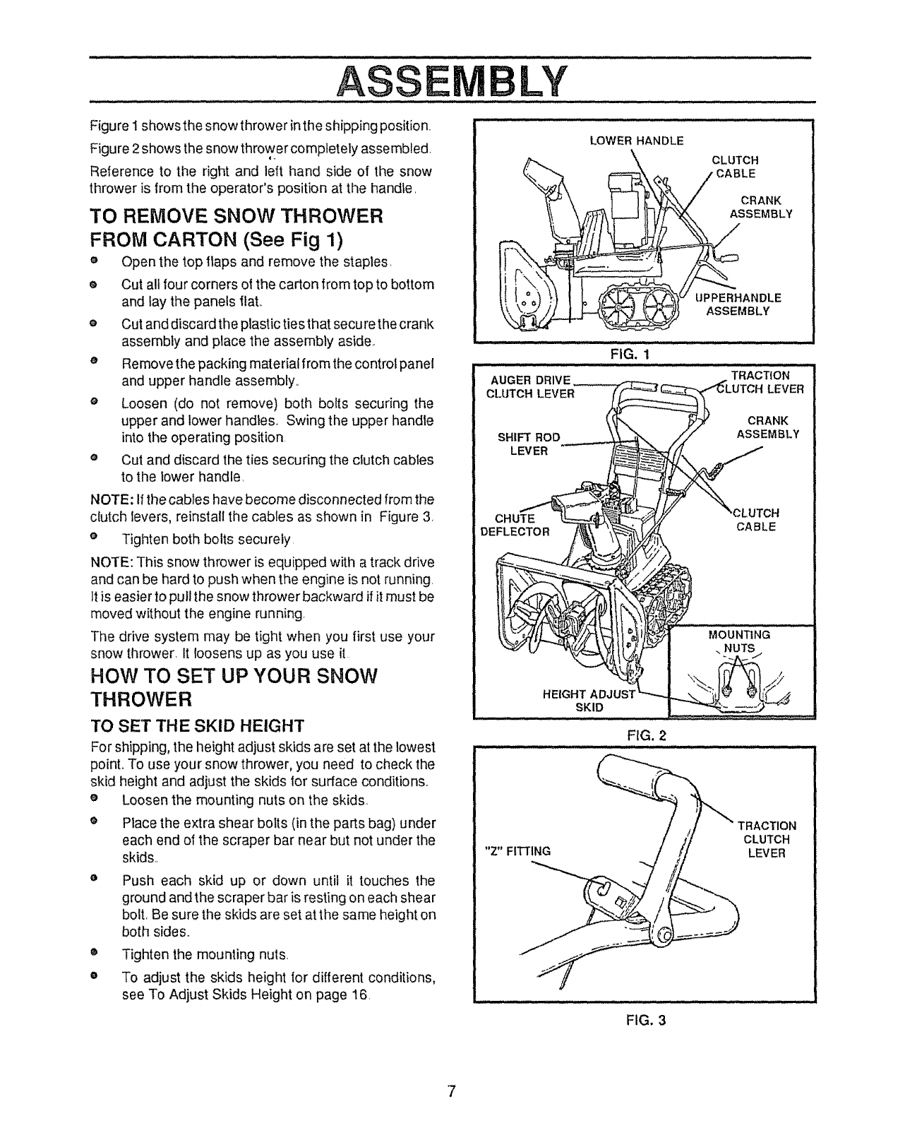
Figure I shows the snow thrower in the shipping position.
Figure 2 shows the snow thrower completely assembled,
Reference to the right and left hand side of the snow
thrower is from the operator's position at the hand_e,
TO REMOVE SNOW THROWER
FROM CARTON (See Fig 1)
e Open the top flaps and remove the staples
® Cut all four corners of the carton from top to bottom
and lay the panels flat.
o Cut and discard the plastic ties that secure the crank
assembly and place the assembly aside_
o Remove the packing material from the control panel
and upper handle assembly,,
o Loosen (do not remove) both bolts securing the
upper and lower handles,, Swing the upper handle
into the operating position,
e Cut and discard the ties securing the clutch cables
to the lower handle.
NOTE: If the cables have become disconnected from the
clutch levers, reinstall the cables as shown in Figure 3,
o Tighten both bolts securely,
NOTE: This snow thrower is equipped with a track drive
and can be hard to push when the engine is not running.
It is easier to pull the snow thrower backward if it must be
moved without the engine running,
The drive system may be tight when you first use your
snow thrower, It loosens up as you use it
HOW TO SET UP YOUR SNOW
THROWER
TO SET THE SKID HEIGHT
For shipping, the height adjust skids are set at the lowest
point. To use your snow thrower, you need to check the
skid height and adjust the skids for surface conditions,
e Loosen the mounting nuts on the skids.,
o Place the extra shear bolts (in the parts bag) under
each end of the scraper bar near but not under the
skids.,
Push each skid up or down until it touches the
ground and the scraper bar is resting on each shear
bolt, Be sure the skids are set at the same height on
both sides,,
o
o
Tighten the mounting nuts.
To adjust the skids height for different conditions,
see To Adjust Skids Height on page 16,
LOWER HANDLE
CLUTCH
CABLE
CRANK
ASSEMBLY
UPPERHANDLE
ASSEMBLY
FIG. 1
FIG, 2
"Z" FITTING
TRACTION
CLUTCH
LEVER
FIG. 3
7
CAUTION: IF YOU ARE REMOVING
,_ SNOW FROM ANY ROCKY OR UNEVEN
SURFACES, RAISE THE FRONT OF THE
SNOW THROWER BY MOVING THE
SKIDS DOWN. THIS WILL HELP TO PREVENT
ROCKS AND OTHER DEBRIS FROM BEING
PICKED UP AND THROWN BY THE AUGER.
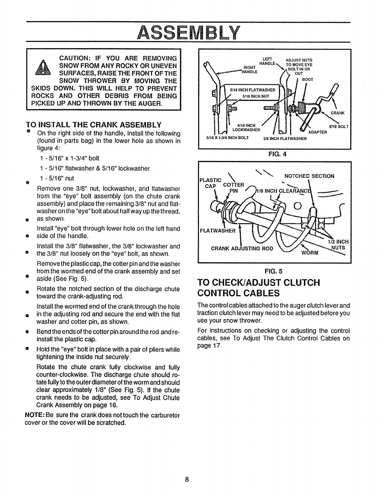
TO INSTALL THE CRANK ASSEMBLY
eOn the right side of the handle, install the following
(found in parts bag) in the lower hote as shown in
o
o
o
o
figure 4:
1 - 5/16" x 1-3/4" bolt
1 - 5/16" flatwasher & 5/16" Iockwasher
1 - 5/16" nut
LY IIIllUIIlllILillllllllllllllIll _IIIllU I II J
illlll ill iilll i_ IHlll ill_l Hj i_ II
RIGHT
51t6 INCH
LOCKWASHEB
Remove one 3/8" nut, lockwasher, and flatwasher
from the "eye" bolt assembly (on the chute crank
assembly) and place the remaining 3/8" nut and flat-
washer on the "eye" bott about half way up the thread,
as shown
5116 X 1-314 INCH BOLT
LEFT ADJUST NUTS
TO MOVE EYE
BOLT IN OR
OUT
BOOT'
Install "eye" bolt through lower hole on the left hand
side of the handle.
install the 3/8" flatwasher, the 3/8" lockwasher and
the 3/8" nut loosely on the "eye" bolt, as shown_
Remove the plastic cap, the cotter pin and the washer
from the wormed end of the crank assembly and set
®aside (See Fig. 5).
Rotate the notched section of the discharge chute
otoward the crank-adjusting rod_
Install the wormed end of the crank through the hole
e in the adjusting rod and secure the end with the flat
washer and cotter pin, as shown.
• Bend the ends of the cotter pin around the rod and re-
install the plastic cap.
o Hold the "eye" bolt in place with a pair of pliers while
tightening the inside nut securely.
Rotate the chute crank fully clockwise and fully
counter-clockwise. The discharge chute should ro-
tate fully to the outer diameteroi the worm and should
clear approximately 1/8" (See Fig 5)° If the chute
crank needs to be adjusted, see To Adjust Chute
Crank Assembly on page 16.
NOTE: Be sure the crank does nottouch the carburetor
cover or the cover will be scratched.
3/8 INCH FLATWASHER
FIG. 4
CAP COTTER
FLATWASHER
CRANK ADJUSTING ROD
I/2 INCH
WORM
illlllllllllllllllll
The control cables attached to the auger clutch lever and
traction clutch lever may need to be adjusted before you
use your snow thrower.
For instructions on checking or adjusting the control
cables, see To Adjust The Clutch Control Cables on
page 17.
w_ NK
EYE BOLT
ADAPTER
NOTCHED SECTION
FIG. 5
TO CHECK/ADJUST CLUTCH
CONTROL CABLES
OPE AT O
:: .... : : :.
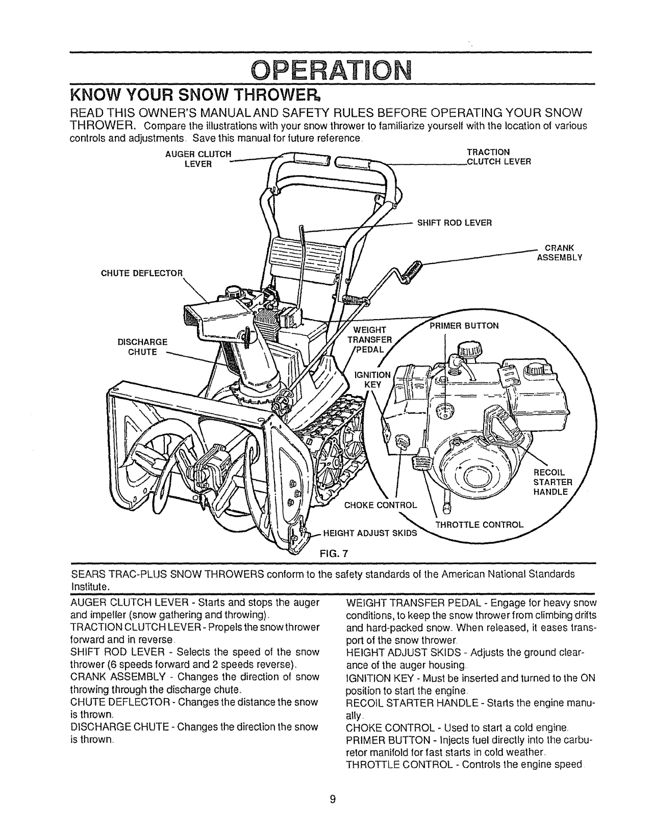
KNOW YOUR SNOW THROWER,
READ THIS OWNER'S MANUALAND SAFETY RULES BEFORE OPERATING YOUR SNOW
THROWER. Compare the illustrationswith your snow thrower to familiarize yourself with the location oi various
controls and adjustments. Save this manual for future reference
AUGER CLUTCH TRACTION
LEVER .CLUTCHLEVER
CHUTE DEFLECTOR
SHIFT ROD LEVER
CRANK
ASSEMBLY
DISCHARGE
CHUTE
WEIGHT
TRANSFER
IGNITION
KEY
BUTTON
RECOIL
STARTER
HANDLE
CHOKE CONTROL
THROTTLE CONTROL
HEIGHT ADJUST
FIG. 7
SEARS TRAC-PLUS SNOW THROWERS conform to the safety standards of the American National Standards
institute,
AUGER CLUTCH LEVER - Starts and stops the auger WEIGHT TRANSFER PEDAL - Engage for heavy snow
and impeller (snow gathering and throwing), conditions, to keep the snow thrower from climbing drifts
TRACTION CLUTCH LEVER-Propels the snow thrower and hard-packed snow,, When released, it eases trans-
forward and in reverse,
SHIFT ROD LEVER - Selects the speed of the snow
thrower (6 speeds forward and 2 speeds reverse),
CRANK ASSEMBLY - Changes the direction of snow
throwing through the discharge chute.,
CHUTE DEFLECTOR - Changes the distance the snow
is thrown,
DISCHARGE CHUTE - Changes the direction the snow
is thrown..
port of the snow thrower,
HEIGHT ADJUST SKIDS - Adjusts the ground clear-
ance of the auger housing.
IGNITION KEY - Must be inseded and turned to the ON
position to start the engine,
RECOIL STARTER HANDLE - Starts the engine manu-
ally.
CHOKE CONTROL - Used to start a cold engine,
PRIMER BUTTON - injects fuel directly into the carbu-
retor manifold for fast starts in cold weather,
THROTTLE CONTROL -Controls the engine speed
9
,, Ill
OPE A=f O
li,,HUll m
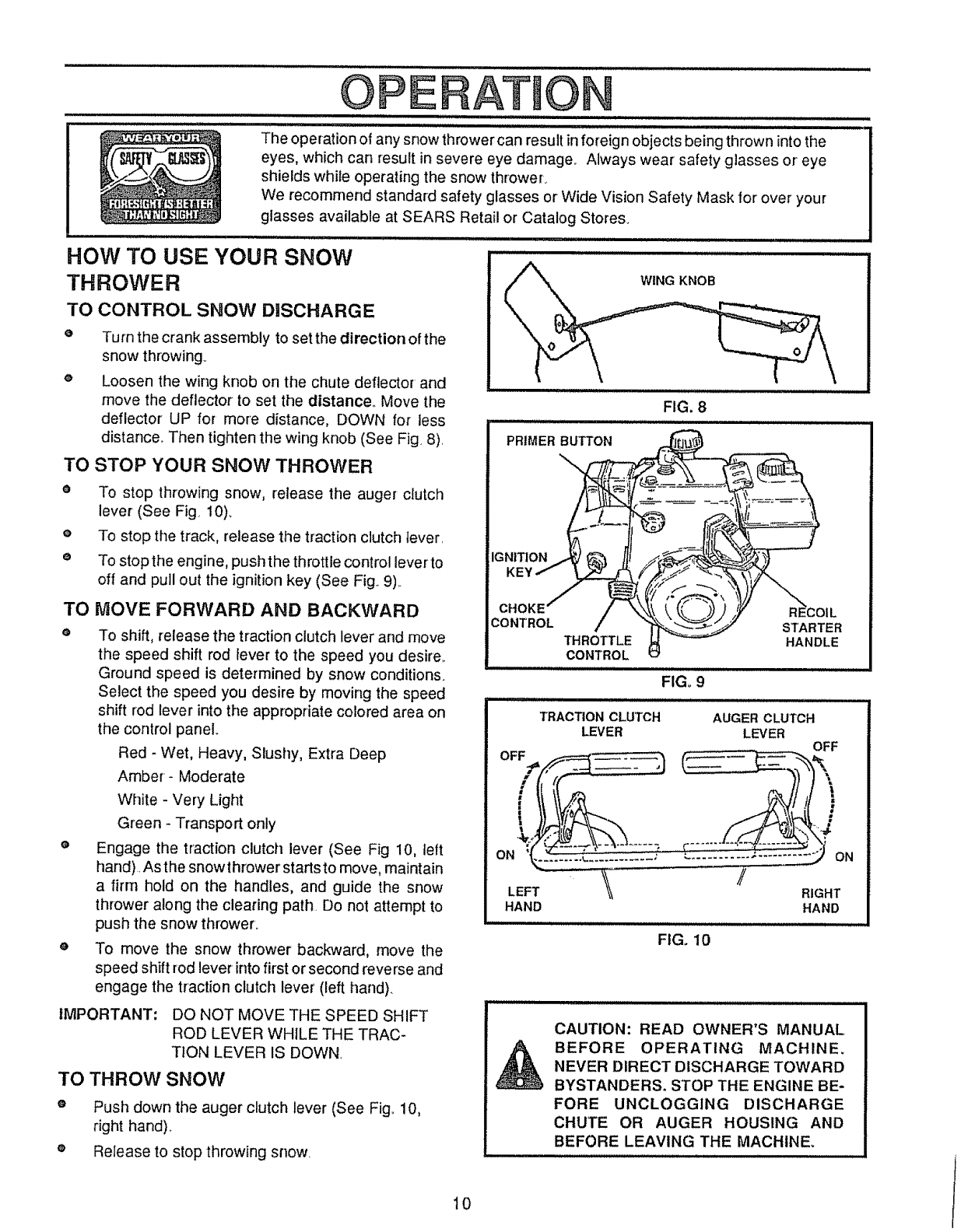
The operation of any snow th rower can result in foreign objects being thrown into the
eyes, which can result in severe eye damage_ Always wear safety glasses or eye
shields while operating the snow thrower.
We recommend standard safety glasses or Wide Vision Safety Mask for over your
glasses available at SEARS Retail or Catalog Stores.
TO
O
HOW TO USE YOUR SNOW
THROWER
CONTROL SNOW DISCHARGE
Turn the crank assembly to set the direction of the
snow throwing_
eLoosen the wing knob on the chute deflector and
move the deflector to set the distance° Move the
deflector UP for more distance, DOWN for less
distance. Then tighten the wing knob (See Fig 8)
TO STOP YOUR SNOW THROWER
• To stop throwing snow, release the auger clutch
lever (See Fig 10)_
eTo stop the track, release the traction clutch tever
e To stop the engine, push the throttle control lever to
off and pull out the ignition key (See Fig 9)
TO
O
o
MOVE FORWARD AND BACKWARD
To shift, release the traction clutch lever and move
the speed shift rod lever to the speed you desire.
Ground speed is determined by snow conditions.
Select the speed you desire by moving the speed
shift rod lever into the appropriate colored area on
the control panel
Red - Wet, Heavy, Slushy, Extra Deep
Amber- Moderate
White - Very Light
Green - Transport only
Engage the traction clutch lever (See Fig 10, tett
hand) As the snowthrower starts to move, maintain
a firm hold on the handles, and guide the snow
thrower along the clearing path Do not attempt to
push the snow thrower.
To move the snow thrower backward, move the
speed shift rod lever into first or second reverse and
engage the traction clutch lever (left hand).
IMPORTANT: DO NOT MOVE THE SPEED SHIFT
ROD LEVER WHJLE THE TRAC-
TION LEVER IS DOWN
TO THROW SNOW
Push down the auger clutch lever (See Fig. 10,
right hand).
Release to stop throwing snow
PRIMER BUTTON
FIG. 8
IGNITION
KEY
CHOKE'
CONTROL
THROTTLE
CONTROL
STARTER
HANDLE
FIGo 9
IU,HI, I:l / / I I I I
TRACTION CLUTCH AUGER CLUTCH
LEVER LEVER OFF
/RIGHT
HAND HAND
=lUl
FIG. 10
CAUTION: READ OWNER'S MANUAL
BEFORE OPERATING MACHINE,
NEVER DIRECT DISCHARGE TOWARD
BYSTANDERS. STOP THE ENGINE BE-
FORE UNCLOGGING DISCHARGE
CHUTE OR AUGER HOUSING AND
BEFORE LEAVING THE MACHINE.
10

OPERATION
TO USE WEIGHT TRANSFER SYSTEM ...................... ..............................
In hard packed or heavy snow conditions, conventional
snow throwers tend to ride up and leave uneven mounds
of snow behind. For these conditions, your new tracked
snow thrower has a unique weight transfer system (See
Fig, 11) designed to minimize ride-up,
Stepping on the weight transfer pedal shiit s more weight
to the auger housing. This weight transfer keeps the
snow thrower in contact with the ground and reduces
ride-up.
In Iighter snow conditions or when transporting, you
should release the weight transfer system 1or easier
steering.
e To use the weight transfer, hold the upper handle
firmly and push down on the weight transfer pedal
(See Fig_ 12) with the ball of your foot.
e To release, pull up on the weight transfer pedal with
the top of your foot.
BEFORE STARTING THE ENGtNE
FILL! ADD OIL:
The engine on this snow thrower was shipped without
oil, Add oil before you start the engine.. Remove the oil
fill cap/dipstick and fill the crank case to FULL line on
dipstick (about 21 ounces) (See Fig.. 13) with S.AE.
10 W-30 motor oil (or equivalent). Do not overfill. Tighten
the fill cap/dipstick securely each time you check the oil
level,,
NOTE: SAE. 5W-30 motor oil may be used to make
starting easier in areas where temperature is consis-
tently 20° F, or lower..
OFF
ON
ENGAG_ /
(ON)
FIGol I
WEIGHT TRANSFER
PEDAL
FIG,12
11,, .... H J , ,iJ ,, , j= ,i i ....
OIL FILL CAPtDIPSTICK
NOTE: OIL LEVEL
MUST BE BETWEEN
FULL AND ADD MARK
FIG,13
il
,H,I i i ..........
OPE ATIO
FILL GAS:
Fill the fuel tank with clean, fresh, unleaded grade auto-
motive gasoline., Be sure that the container you pour the
gasoline from is clean and free from rust or other foreign
particles.. Never use gasoline that may be stale from long
periods of storage in the container°
WARNING: Experience indicates that alcohol blended
fuels (called gasohol or' using ethanol or methanol) can
attract moisture which leads to separation and formation
of acids during storage.. Acidic gas can damage the fuel
system of an engine while in storage,
To avoid engine problems, the fuel system should be
emptied before storage for 30 days or longer'.. Drain the
gas tank, start the engine and let it run until the fuet lines
and carburetor are empty.. Use the carburetor bowl drain
to empty residual gasoline from the float chamber
(Figure 39).. Use fresh fuel next season.. (See Storage
instructions on page 23 for additional information..)
Never use engine or carburetor cleaner products in the
fuel tank or permanent damage may occur.
_ AUTION: GASOLINE IS FLAMMABLE
AND CAUTION MUST BE USED WHEN
HANDLING OR STORING IT.
DO NOT FILL FUEL TANK WHILE SNOW
THROWER iS RUNNING,WHEN IT IS HOT, OR
WHEN SNOW THROWER IS tN AN ENCLOSED
AREA.
KEEP AWAY FROM OPEN FLAME OR AN ELEC-
TRICAL SPARK AND DO NOT SMOKE WHILE
FILLING THE FUEL TANK.
NEVER FILL THE TANK COMPLETELY. FILL
TH ETANK TO WITHIN 1/4"- 1/2" FROM TH E TOP
TO PROVIDE SPACE FOR EXPANSION OF FUEL.
ALWAYS FILL FUEL TANK OUTDOORS AND
USE A FUNNEL OR SPOUTTO PREVENTSPILL-
ING.
MAKE SURE TO WIPE UP ANY SPILLED FUEL
BEFORE STARTING THE ENGINE.
STORE GASOLINE IN A CLEAN, APPROVED
CONTAINER AND KEEP THE CAP IN PLACE ON
THE CONTAINER°
CAUTION: NEVER RUN ENGINE IN-
DOORS OR IN ENCLOSED, POORLY
VENTILATED AREAS. ENGINE EX-
HAUST CONTAINS CARBON MON-
OXIDE, AN ODORLESS AND DEADLY GAS.
KEEP HANDS, FEET, HAIR AND LOOSE CLOTH-
ING AWAY FROM ANY MOVING PARTS ON
ENGINE AND SNOW THROWER=
WARNING: TEMPERATURE OF MUFFLER AND
NEARBY AREAS MAY EXCEED 150°F. AVOID
THESE AREAS.
DO NOT ALLOW CHILDREN OR YOUNG TEEN-
AGERS TO OPERATE OR BE NEAR SNOW
THROWER WHILE IT IS OPERATING.
TO STOP ENGmNE
eTo stop engine, move the throttle control lever to
"STOP" position and remove key. Keep the key in a
safe place_ The engine will not start without the key.
TO START ENGINE
Be sure that the engine has sufficient oil. Before starting
the engine, be certain that you have read the following
information:
COLD START (See Fig. 14)
OBe sure the auger and the traction clutch levers are
in the disengaged "RELEASED" position.
®Move the throttle control up to "FAST" position.
®Push the key into the ignition slot. Be sure it snaps
into place, Do not turn key.
o
o
o
Rotate choke control to "FULL" choke position,
Press the primer button two or three times, while
keeping your finger' over the vent hole on the primer
button. Additional priming may be necessary for the
first start if the temperature is below 15° F,
Pull the starter handle rapidly, Do not allow the
handle to snap back, but allow it to rewind slowly
while keeping a firm hold on the starter handle.
As the engine warms up and begins to operate
evenly, rotate the choke knob slowly to "OFF" posi-
tion. If the engine falters, return to "FULL" choke,
then slowly move to "OFF" choke position.
NOTE: Allow the engine to warm up for a few minutes
because the engine will not develop full power until it
reaches operating ternperature.
eRun the engine at or near the top speed when
throwing snow..
12
OPERATION
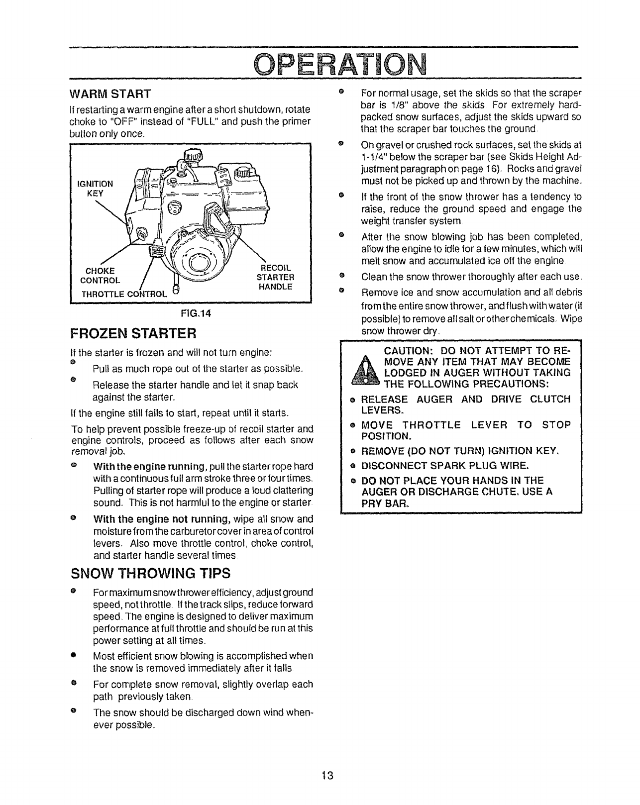
WARM START o
If restarting a warm engine after a short shutdown, rotate
,hoke to "OFF" instead of "FULL" and push the primer
)utton only once.
J .... ,, , _,,_..... _1 u..ll .i.i -
IGNITION
KEY
CHOKE RECOIL
CONTROL STARTER
HANDLE
THROTTLE CONTROL
/L iuju...., -
FIG.14
FROZEN STARTER
tf the starter is frozen and will not turn engine:
oPutl as much rope out of the starter as possible.
eRelease the starter handle and let it snap back
against the starter_
If the engine still fails to start, repeat unlit it starts..
To help prevent possible freeze-up of recoil starter and
engine controls, proceed as follows after each snow
removal job,.
o With the engine running, putl the starter rope hard
with a continuous full arm stroke three or four times.
Pulling of starter rope will produce a loud clattering
sound. This is not harmlu! to the engine or starter
eWith the engine not running, wipe all snow and
moistu refrom the carburetor cover in area of control
levers_ Also move throttle control, choke control,
and starter handle several times.
SNOW THROWING TIPS
o For maximum snow thrower efficiency, adjust ground
speed, not throttle. Ifthe track slips, reduce forward
speed_ The engine isdesigned to deliver maximum
performance at full throttle and shou{d be run at this
power setting at all times..
•Most efficient snow blowing is accomplished when
the snow is removed immediately after it falls
eFor complete snow removal, slightly overlap each
path previously taken.
eThe snow should be discharged down wind when-
ever possible..
o
o
For normal usage, set the skids so that the scraper
bar is 1/8" above the skids. For extremefy hard-
packed snow surfaces, adjust the skids upward so
that the scraper bar touches the ground
On gravel or crushed rock surfaces, set the skids at
1-1/4" below the scraper bar (see Skids Height Ad-
justment paragraph on page 16). Rocks and gravel
must not be picked up and thrown by the machine..
If the front of the snow thrower has a tendency to
raise, reduce the ground speed and engage the
weight transfer system.
After the snow blowing iob has been completed,
allow the engine to idle for a few minutes, which will
melt snow and accumulated ice off the engine
Clean the snow thrower thoroughly after each use,
Remove {ce and snow accumulation and all debris
from the entire snow thrower, and flush with water (it
possible) to remove all salt orotherchemicals. Wipe
snow thrower dr_'_
..... ,, _........... IIH ...........
CAUTION: DO NOT ATTEMPT TO RE-
MOVE ANY ITEM THAT MAY BECOME
LODGED IN AUGER WITHOUT TAKING
THE FOLLOWING PRECAUTIONS:
oRELEASE AUGER AND DRIVE CLUTCH
LEVERS.
e MOVE THROTTLE LEVER TO STOP
POSITION.
aREMOVE (DO NOT TURN) IGNITION KEY,
e DISCONNECT SPARK PLLtG WIRE.
e DO NOT PLACE YOUR HANDS IN THE
AUGER OR DISCHARGE CHUTE. USE A
PRY BAR.
t3

Al TE A OE
GENERA L RECONMENDATiONS o._(C.A,.SAN0SPROCKETS)
The warranty on this snow thrower does not cover items
that have been subjected to operator abuse or negli-
gence To receive full value from the warranty, operator
must maintain snow thrower as instructed in this manual.
Some adjustments wilt need to be made periodically to
properly maintain your' snow thrower.
All adjustments in the Service and Adjustments section
of this manual should be checked at least once each sea-
son
AFTER FIRST USE
eCheck the tracks for tension and adjust if necessary
(See Adjust Track paragraph on page 21)_ Check
the track adjustment and fasteners regularly
o Be sure that all fasteners are tight
AS REQUIRED
The following adjustments should be performed more
than once each season,,
eAuger' and Track Drive Belts should be adjusted after
the first 2 to 4 hours of use and again about mid-
season and twice each season thereafter. See To
Adjust Belts paragraph on page 17,
eAll screws and nuts should be checked often to make
sure they are tight, preferably after each use•
SNOW THROWER
HEX SHAFT
DISC DRI_¢E PLATE
FIG.16
LUBRICATION - EVERY TEN HOURS
® Chain and Sprockets- Oilchains and sprockets (See
Fig. 15) with 10W-30 oil (orequivalent) after i 0 hours
use and at the end of each season
LUBRICATION - NOT REQUIRED
o Hex Shaft and Gears - Hex shaft and gear's require
no lubrication. All bearings and bushings are lifetime
lubricated and require no maintenance (See Fig.
16).
NOTE: Any greasing or oiling of the above components
can cause contamination of the friction wheel. If the disc
drive plate or friction wheel come in contact with grease
or oil, damage to the friction wheel will result..
Should grease or oil come in contact with the disc drive
plate or friction wheel, be sure to clean the plate and
wheel thoroughty_
NOTE: For storage, the hex shaft and gears should be
wiped with 10W-30 motor oil to prevent rusting (See Fig.
16),
e Auger Gear Box - The auger gear box has been
factory lubricated for life. If for some reason lubricant
should leak out, have the auger gear' case checked
by a competent repairman_ 14
TENANCE
ENGINE ...................
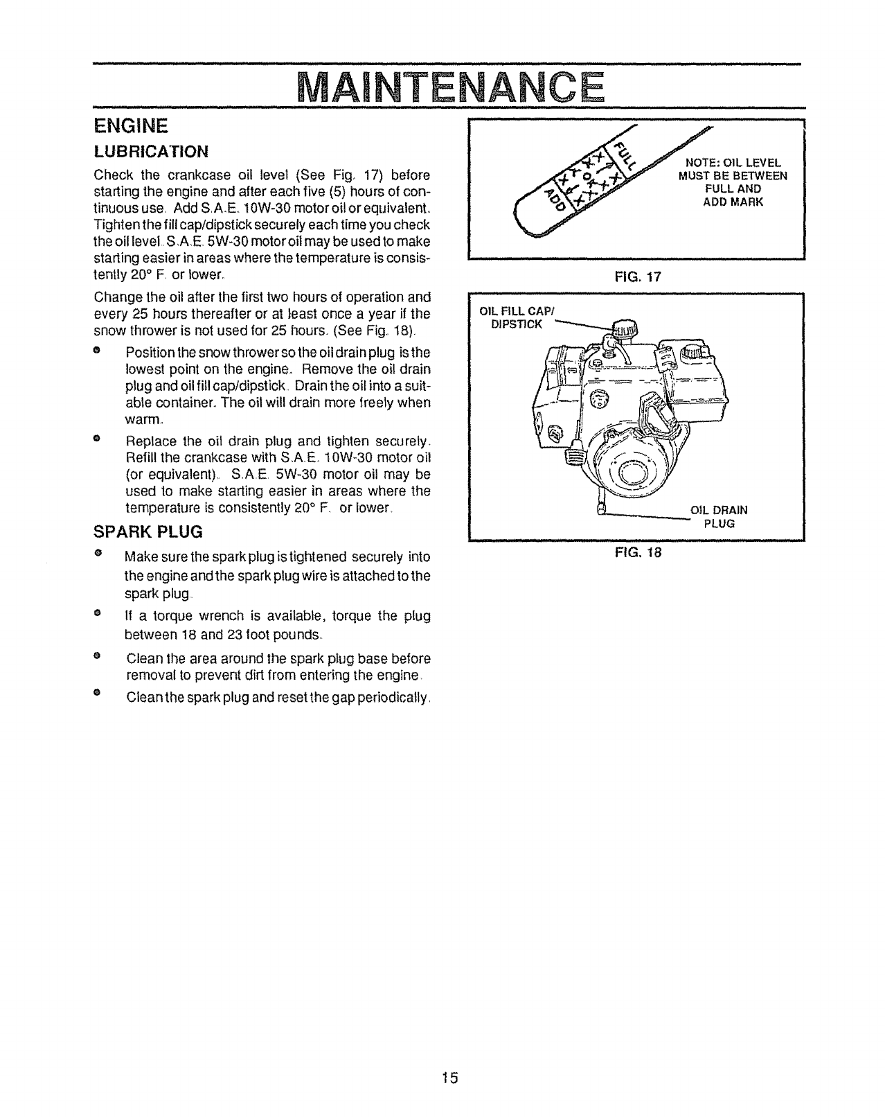
.E(. NOTE: OIL LEVEL
MUST BE BETWEEN
FULL AND
ADD MARK
LUBRICATION
Check the crankcase oil level (See Fig 17) before
starting the engine and after each five (5) hours of con-
tinuous use, Add S,A_E.,10W-30 motor oil or equivalenL
Tighten the fill cap/dipstick securely each time you check
the oil level, S,AE. 5W-30 motor oil may be used to make
starting easier in areas where the temperature is consis-
tently 20° F, or lower°
- • , _.............,, i ,ll ii ill i ii
FIG, 17
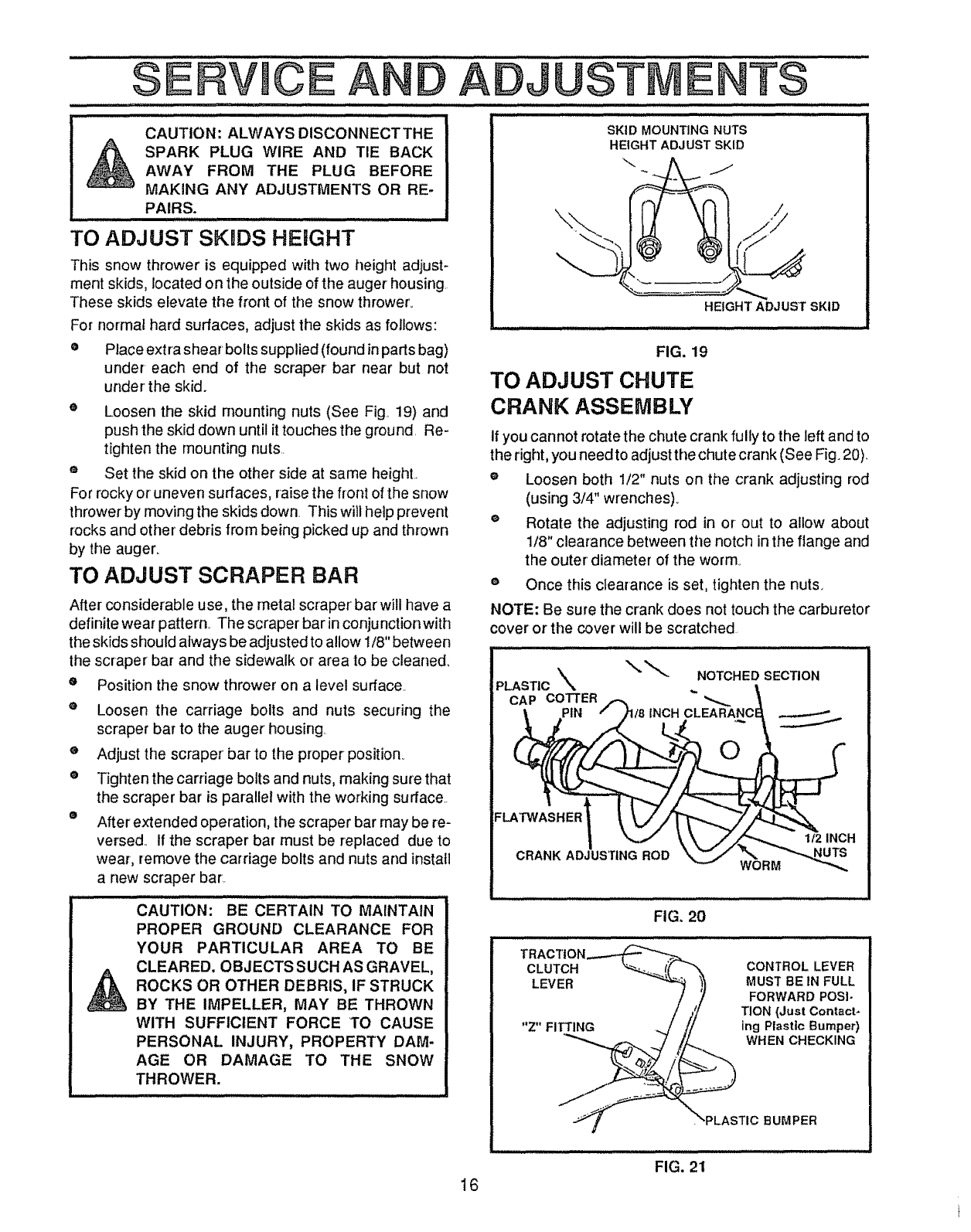
Change the oil after the first two hours of operation and
every 25 hours thereafter or at }east once a year if the
snow thrower is not used for 25 hours.• (See Fig., 18).
e Position the snow thrower so the oil drain plug isthe
lowest point on the engine_ Remove the oil drain
plug and oil fill cap/dipstick, Drain the oil into a suit-
able container. The oil will drain more freely when
warm.
Replace the oit drain plug and tighten securely_
Refill the crankcase with SA.E_ 10W-30 motor oi!
(or equivalent)., S,A.E. 5W-30 motor oil may be
used to make starting easier in areas where the
temperature is consistently 20° F. or lower,
SPARK PLUG
oMake su re the spark plug is tightened securely into
the engine and the spark plugwire is attached to the
spark plug,,
o If a torque wrench is available, torque the plug
between 18 and 23 foot pounds.
OIL FILL CAP/
DIPSTICK
@
OJL DRAIN
PLUG
""; ..........FIGI ........
Clean the area around the spark plug base before
removal to prevent dirt from entering the engine.
Clean the spark plug and reset the gap periodicatly,
15
SERVMCE
,, ,H,
CAUTION: ALWAYS DISCONNECTTHE
SPARK PLUG WIRE AND TIE BACK
AWAY FROM THE PLUG BEFORE
MAKING ANY ADJUSTMENTS OR RE-
PAIRS. .............................
m=,
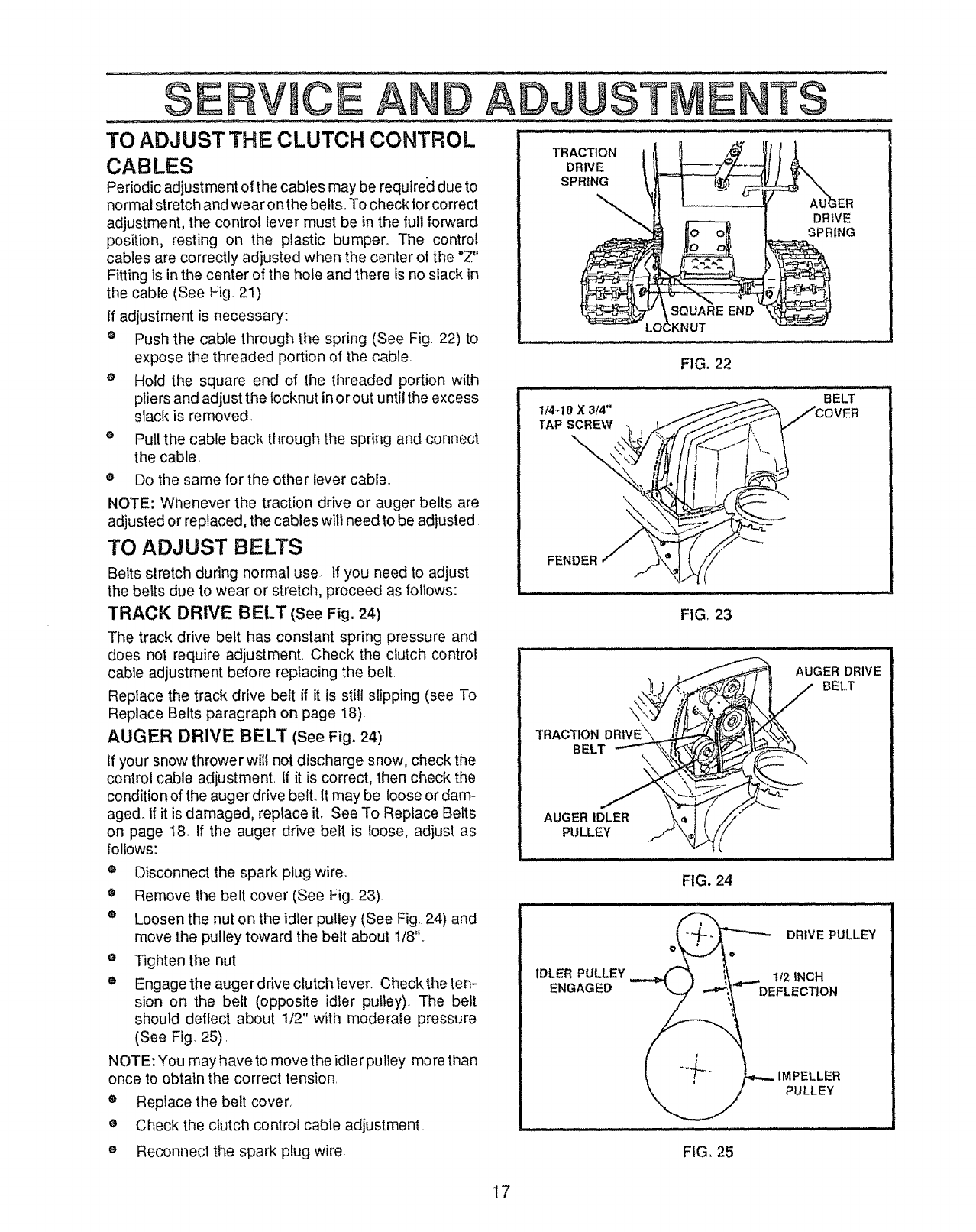
TO ADJUST SKnDS HEIGHT
ANDADJUST E TS
SKID MOUNTING NUTS
HEIGHT ADJUST SKID
This snow thrower is equipped with two height adjust-
ment skids, located on the outside of the auger housing.
These skids elevate the front of the snow thrower°
For normal hard surfaces, adjust the skids as follows:
o Place extra shear' bolts supplied (found inparts bag)
under each end of the scraper bar near but not
under the skid.
eLoosen the skid mounting nuts (See Fig 19) and
push the skid down until it touches the ground. Re-
tighten the mounting nuts.
= Set the skid on the other side at same height..
For rocky or uneven surfaces, raise the front of the snow
thrower by moving the skids down. This will help prevent
rocks and other debris from being picked up and thrown
by the auger.
TO ADJUST SCRAPER BAR
After considerable use, the metal scraper bar will have a
definite wear pattern. The scraper barin conjunctionwith
the skids should always be adjusted to allow 1/8" between
the scraper bar and the sidewalk or area to be cleaned_
ePosition the snow thrower' on a level surface
eLoosen t!le carriage bolts and nuts securing the
scraper bar to the auger housing
eAdjust the scraper' bar to the proper position..
eTightenthe carriage bolts and nuts, making sure that
the scraper bar is parallel with the working surface..
®After extended operation, the scraper bar may be re-
versed.. If the scraper bar must be replaced due to
wear, remove the carriage bolts and nuts and install
a new scraper bar.
"' cA ' ,o .........................
N: BE CERTAIN TO MAINTAIN
PROPER GROUND CLEARANCE FOR
YOUR PARTICULAR AREA TO BE
CLEARED. OBJECTS SUCH AS GRAVEL,
A ROCKS OR OTHER DEBRIS, IF STRUCK
BY THE IMPELLER, MAY BE THROWN
WITH SUFFICIENT FORCE TO CAUSE
PERSONAL INJURY, PROPERTY DAM-
AGE OR DAMAGE TO THE SNOW
THROWER.
................ .............. : ,,,,luu
HEIGHT ADJUST SKID
FIG. 19
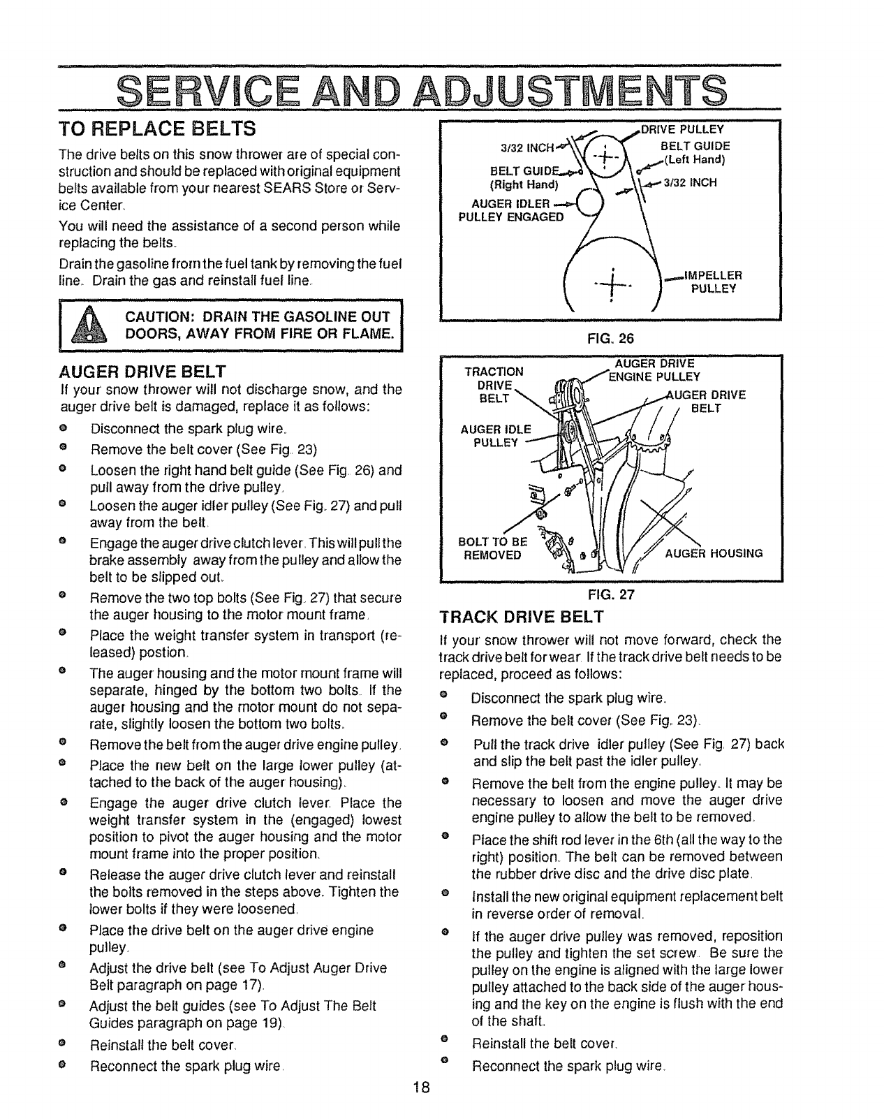
TO ADJUST CHUTE
CRANK ASSEMBLY
if you cannot rotate the chute crank fully to the left and to
the right, you needto adjust the chute crank (See Fig. 20)_
e Loosen both 1/2" nuts on the crank adjusting rod
(using 3/4" wrenches).
®Rotate the adjusting rod in or out to allow about
1/8" clearance between the notch in the flange and
the outer' diameter of the worm°
e Once this clearance is set, tighten the nuts.
NOTE: Be sure the crank does not touch the carburetor
cover or the cover will be scratched
PLASTIC _. NOTCHED SECTION
CAP COTTER
PIN NCH CLEARANC
ROD
FIG. 20
1/2 INCH
WORM
TRACTION
CLUTCH CONTROL LEVER
LEVER MUST BE IN FULL
FORWARD POSI-
TION (Just Contact-
"Z" FITI"ING ing Plastic Bumper)
WHEN CHECKING
16
. "PLASTIC BUMPER
FIG. 21
SERVmCE AND ADJUSTME T$
TO ADJUST THE CLUTCH CONTROL _ " ....:: .... ......
CABLES
Periodic adjustment of the cables may be required due to
normal stretch and wear on the belts,.To check for correct
adjustment, the control lever must be in the full forward
position, resting on the plastic bumper.. The control
cables are correctly adjusted when the center of the "Z"
Fitting is in the center of the hole and there is no slack in
the cable (See Fig. 21)
If adjustment is necessary:
oPush the cable through the spring (See Fig. 22) to
expose the threaded portion of the cable.
o Hold the square end of the threaded portion with
pliers and adjust the locknut in or out until the excess
slack is removed..
o Pul! the cable back through the spring and connect
the cable,
® Do the same for the other lever cable°
NOTE: Whenever the traction drive or auger belts are
adjusted or replaced, the cables will need to be adjusted.
TO ADJUST BELTS
Belts stretch during normal use. tf you need to adjust
the belts due to wear or stretch, proceed as follows:
TRACK DRIVE BELT (See Fig. 24)
The track drive belt has constant spring pressure and
does not require adjustment. Check the clutch control
cable adjustment before replacing the belt.
Replace the track drive belt if it is still slipping (see To
Replace Belts paragraph on page 18).
AUGER DRIVE BELT (see Fig. 24)
tf your snow thrower wilt not discharge snow, check the
control cable adjustment. If it is correct, then check the
conditio n of the auger drive bell It may be loose or dam-
aged. If it is damaged, replace it. See To Replace Belts
on page 18o If the auger drive belt is loose, adjust as
follows:
o Disconnect the spark plug wire.
®Remove the belt cover (See Fig. 23).
e Loosen the nut on the idler pulley (See Fig. 24) and
move the pulley toward the belt about 1/8"**
o Tighten the nut.
• Engage the auger drive clutch lever. Checktheten-
sion on the belt (opposite idler pulley)_ The belt
should deflect about 1/2" with moderate pressure
(See Fig. 25).
NOTE: You may have to move the idler pulley more than
once to obtain the correct tension.
® Replacethe belt cover,
eCheck the clutch control cable adjustment
TRACTION
DRIVE
SPRING
DRIVE
SPRING
FIG. 22
I/4-10 X 3/4"
TAP SCREW
\
BELT
FENDER
FIG.23
AUGER DRIVE
BELT
TRACTION DRIVE'\
BELT
AUGER IDLER
PULLEY
FIG. 24
DRIVE PULLEY
IDLER PULLEY t12 INCH
ENGAGED DEFLECTION
IMPELLER
PULLEY
o Reconnect the spark plug wire FIG,, 25
17
SERViCEA D ADJUST ENTS
TO REPLACE BELTS
The drive belts on this snow thrower are of special con-
struction and should be replaced with original equipment
beetsavailable from your nearest SEARS Store or Serv-
ice Center.
You will need the assistance of a second person while
replacing the belts..
Drain the gasoline from the fuel tank by removing the fuel
line.. Drain the gas and reinstall fuel line._
..........................,HI JULLU U,, ,I ,llll III
!_ CAUTION'. DRAIN THE GASOLINE OUT i
DOORS, AWAY FROM FIRE OR FLAME.
J,,i .............
AUGER DRIVE BELT
if your snow thrower will not discharge snow, and the
auger drive belt is damaged, replace it as follows:
e Disconnect the spark plug wire.
eRemove the belt cover (See Fig.. 23)
e Loosen the right hand belt guide (See Fig. 26) and
pull away from the drive pulley.
e Loosen the auger idler pulley (See Fig..27) and pull
away from the belt.
eEngage the auger drive clutch lever. This will pullthe
brake assembly away from the pulley and allow the
belt to be slipped ouL
e Remove the two top bolts (See Fig 27) that secure
the auger housing to the motor mount frame.
e Place the weight transfer system in transport (re-
leased) postion
eThe auger housing and the motor mount frame will
separate, hinged by the bottom two bolts If the
auger housing and the motor mount do not sepa-
rate, slightly loosen the bottom two bolts._
e Remove the belt from the auger drive engine pulley
e Place the new belt on the large lower pulley (at-
tached to the back of the auger housing)..
eEngage the auger drive clutch lever. Place the
weight transfer system in the (engaged) lowest
position to pivot the auger housing and the motor
mount frame into the proper position.
eRelease the auger drive clutch lever' and reinstall
the bolts removed in the steps above_ Tighten the
lower bolts if they were loosened.
e Place the drive belt on the auger drive engine
pulley.
eAdjust the drive belt (see To Adjust Auger Drive
Belt paragraph on page 17).
e Adjust the belt guides (see To Adjust The Belt
Guides paragraph on page 19).
eReinstall the belt cover.
e Reconnect the spark plug wire.
.._,,:,...._ ...,,,.DRIVE PULLEY:
3t32 INCH"_'_K _ "_-- BELT GUIDE
BELT GUIDF_:._\ • "_(Left Hand)
,.o?. ,- ,.c,
I._l }_IMPELLER
JH,H ,,,,I llll I,,,
FIG. 26
iiiii
TRACTION
DRIVE.
BELT "_
AUGER DRIVE ...........
PULLEY
DRIVE
BELT
AUGER IDLE
PULLEY
BOLl"TO BE
REMOVED AUGER HOUSING
FIG, 27
"[RACK DRIVE BELT
If your' snow thrower witl not move forward, check the
track drive belt for wear. If the track drive belt needs to be
replaced, proceed as follows:
eDisconnect the spark plug wire.
®Remove the belt cover (See Fig,. 23).
ePull the track drive idler' pulley (See Fig. 27) back
and slip the belt past the idler pulley..
eRemove the belt from the engine pulley. It may be
necessary to loosen and move the auger drive
engine pulley to allow the belt to be removed.
oPlace the shift rod lever in the 6th (all the way to the
right) position. The belt can be removed between
the rubber drive disc and the drive disc plate.
eInstall the new original equipment replacement belt
in reverse order' of removal.
e
o
o
If the auger drive pulley was removed, reposition
the pulley and tighten the set screw. Be sure the
pulley on the engine is aligned with the large lower
pulley attached to the back side of the auger hous-
ing and the key on the engine is flush with the end
of the shaft..
Reinstall the belt cover.
Reconnect the spark plug wire
18
SERV CEAN ADJUSTME TS
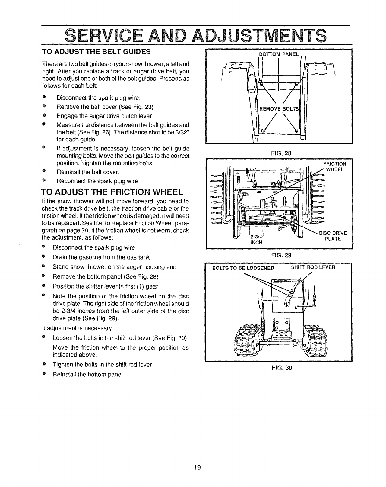
TO ADJUST THE BELT GUIDES
There are two belt guides on your snow thrower, a left and
righL After you replace a track or auger drive belt, you
need to adjust one or both of the belt guides Proceed as
follows for each belt:
•Disconnect the spark plug wire.
® Remove the belt cover (See Fig. 23)
® Engage the auger drive clutch lever.
® Measure the distance between the belt guides and
the belt (See Fig. 26)..The distance should be 3/32"
for each guide.
® If adjustment is necessary, loosen the belt guide
mounting bolts.. Move the belt guides to the correct
position. Tighten the mounting bolts•
• Reinstall the belt cover..
o Reconnect the spark plug wire,
TO ADJUST THE FRICTION WHEEL
If the snow thrower will not move forward, you need to
check the track drive belt, the traction drive cable or the
friction wheel. Ifthe friction wheel is damaged, it will need
to be replaced. See the To Replace Friction Wheel para-
graph on page 20. If the fdction wheel is not worn, check
the adjustment, as follows:
Disconnect the spark plug wire,.
Drain the gasoline from the gas tank_
e Stand snow thrower on the auger housing end..
o Remove the bottom panel (See Fig 28).
® Position the shifter lever in first (1) gear.
® Note the position of the friction wheel on the disc
drive plate.. The right side of the friction wheel should
be 2-3/4 inches from the left outer side of the disc
drive plate (See Fig.. 29)_
If adjustment is necessary:
e Loosen the bolts in the shift rod lever (See Fig. 30).
Move the friction wheel to the proper position as
indicated above.
o Tighten the bolts in the shilt rod lever.
® Reinstallthe bottom panel.
INCH
DRIVE
PLATE
FIG. 29
BOLTS TO BE LOOSENED
iiilll ,Ul i lll ................... ,i
SHIFT ROD LEVER
/
6
FIG, 30
19
SERVICE A
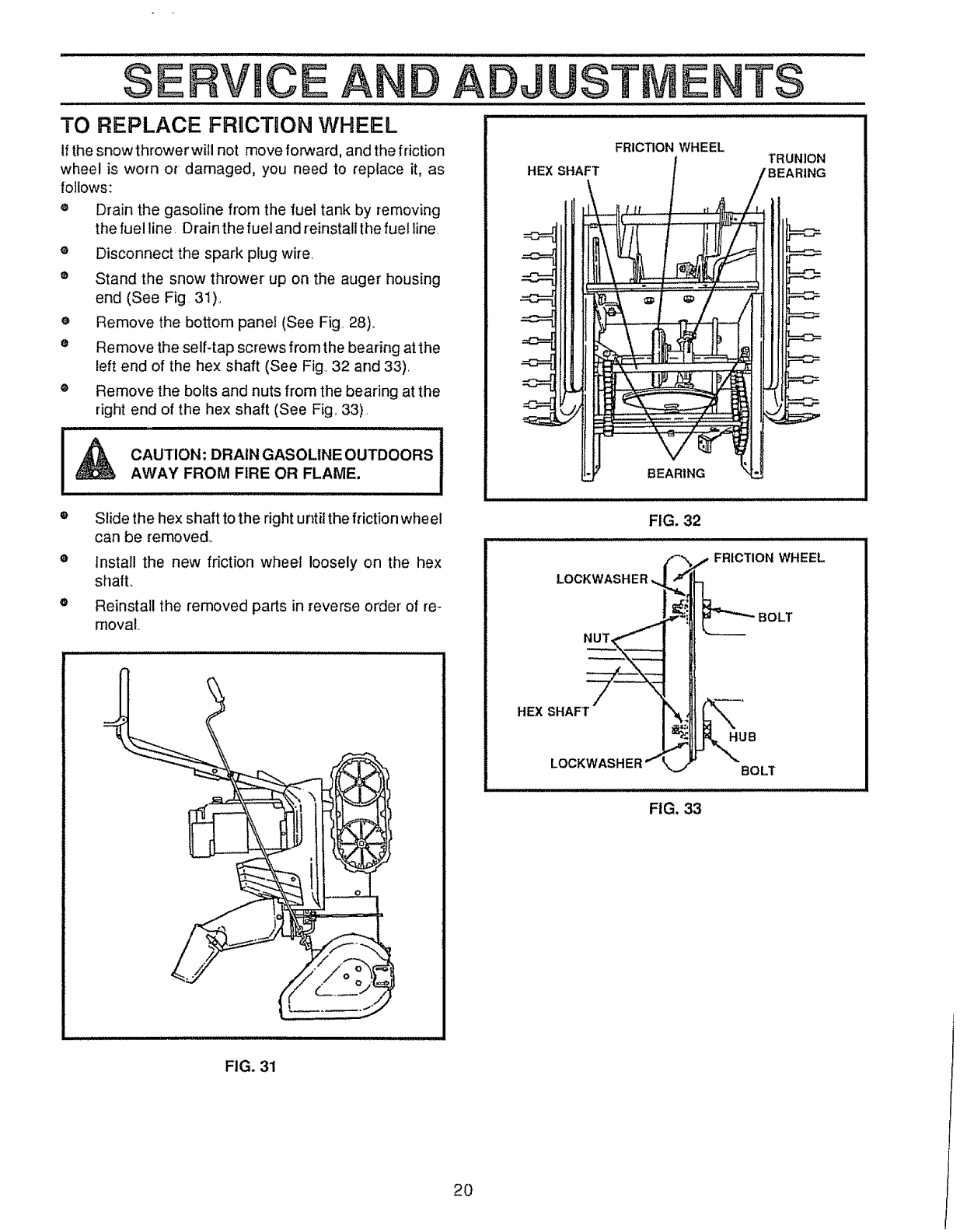
TO REPLACE FRICTION WHEEL
if the snowthrower will not move forward, and the friction
wheel is worn or damaged, you need to replace it, as
follows:
o Drain the gasoline from the fuel tank by removing
the fuel line Drain the fuel and reinstall the fuel line,
o Disconnect the spark plug wire,
® Stand the snow thrower up on the auger housing
end (See Fig 31)o
e Remove the bottom panel (See Fig. 28),
• Remove the self-tap screws from the bearing at the
left end of the hex shaft (See Fig. 32 and 33).
® Remove the bolts and nuts from the bearing at the
right end of the hex shaft (See Fig. 33)
CAUTION: DRAIN GASOLINE OUTDOORS
AWAY FROM FIRE OR FLAME.
ADJUST E T$
FRICTION WHEEL
HEX SHAFT TRUNION
BEARING
Slide the hex shaft to the right until the frictionwheel
can be removed,,
install the new friction wheel loosely on the hex
shall
Reinstall the removed parts in reverse order of re-
moval,
FIG. 32
LOCKWASHER
NUT,
BOLT
HEX SHAFT
HUB
LOCKWASHER BOLT
FIG, 33
FIG. 31
2O
SERVICE AND ADJUSTME TS
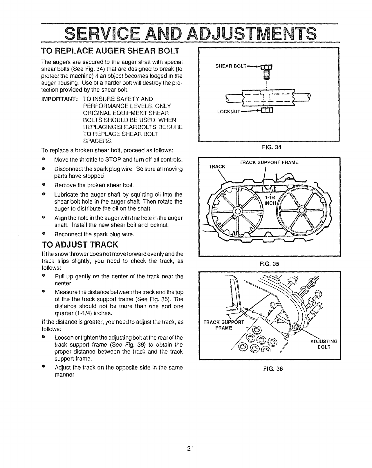
TO REPLACE AUGER SHEAR BOLT ..... ........ .......... ....
The augers are secured to the auger shaft with special
shear bolts (See Fig,. 34) that are designed to break (to
protect the machine) if an object becomes lodged in the
auger housing. Use of a harder bolt will destroy the pro-
tection provided by the shear bolt.
IMPORTANT: TO INSURE SAFETY AND
PERFORMANCE LEVELS, ONLY
ORIGINAL EQUIPMENT SHEAR
BOLTS SHOULD BE USED. WHEN
REPLACING SHEAR BOLTS, BE SURE
TO REPLACE SHEAR BOLT
SPACERS
To replace a broken shear bolt, proceed as follows:
Move the throttle to STOP and turn off all controls.
o
o
O
o
e
Disconnect the spark plug wire. Be sure all moving
parts have stopped.
Remove the broken shear bolt
Lubricate the auger shaft by squirting oil into the
shear bolt hole in the auger shaft. Then rotate the
auger to distribute the oil on the shaft
Align the hole in the auger with the hole in the auger
shaft. Install the new shear bolt and Iocknut
o Reconnect the spark plug wire.
TO ADJUST TRACK
Ifthe snow thrower does not move forward evenly and the
track slips slightly, you need to check the track, as
follows:
ePull up gently on the center ol the track near the
center..
• Measure the distance between the track and the top
of the the track support frame (See Fig 35).. The
distance should not be more than one and one
quarter (1-I14) inches,
tf the distance is greater, you need to adjust the track, as
follows:
o Loosen or tighten the adjusting bolt at the rear of the
track support frame (See Fig.. 36) to obtain the
proper distance between the track and the track
support frame.
® Adjust the track on the opposite side in the same
manner.
SHEAR BOLT_
: L ,,i LI i,,..................... i,,_l_
FIG. 34
TRACK SUPPORT FRAME
FIG. 35
TRACK SUPPORT
FRAME
ADJUSTING
BOLT
FIG. 36
21
SERVmCE
,i i,
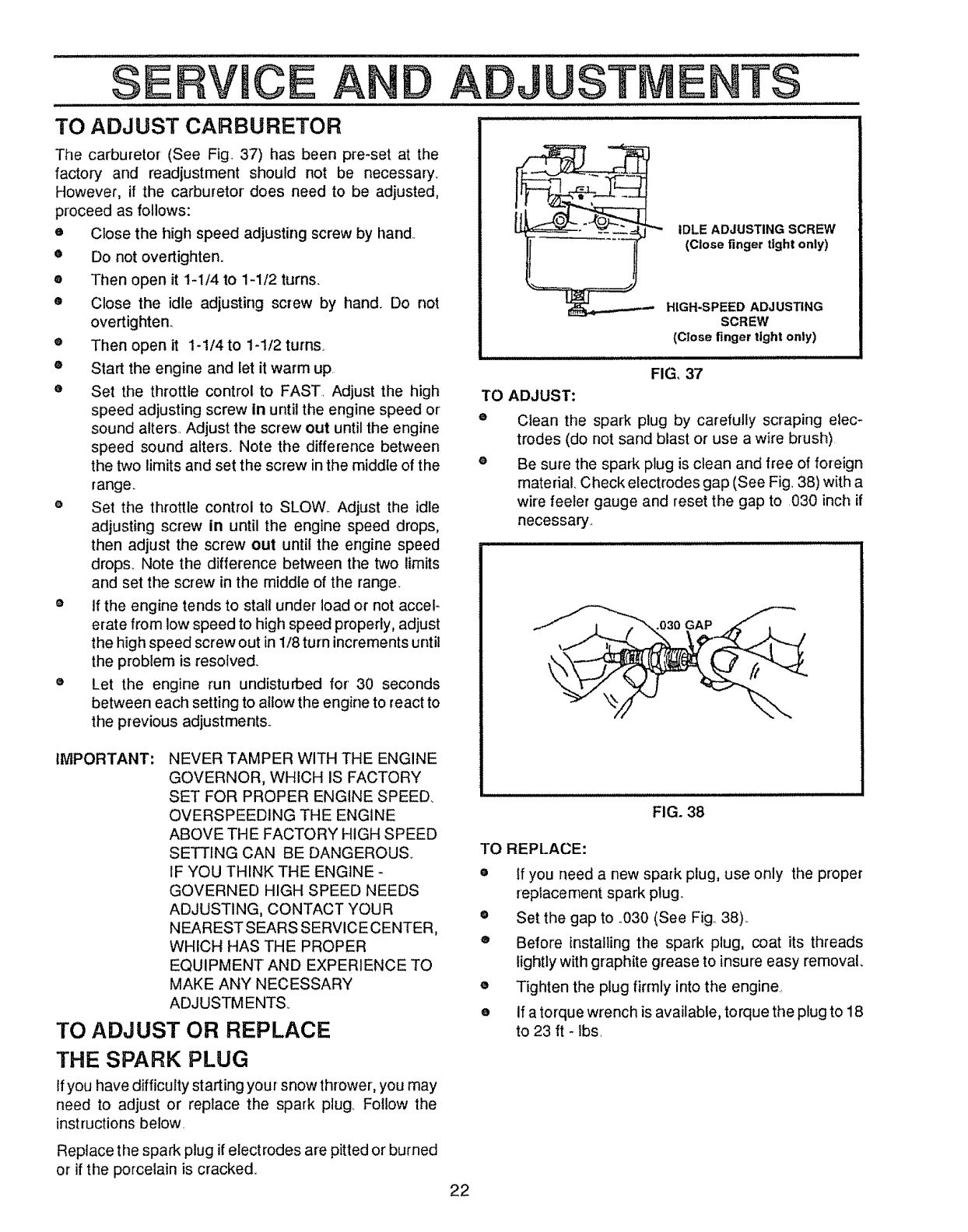
TO ADJUST CARBURETOR
AND A
TO ADJUST:
Q
The carburetor (See Fig. 37) has been pre-set at the
factory and readjustment should not be necessary.
However, if the carburetor does need to be adjusted,
proceed as follows:
e Close the high speed adjusting screw by hand
• Do not overtighten.
® Then open it 1-!/4 to 1-1/2 turns.
• Close the idle adjusting screw by hand. Do not
overtighten.
e Then open it 1-114 to 1-112 turns.
® Start the engine and let it warm up.
e Set the throttle control to FAST. Adjust the high
speed adjusting screw in until the engine speed or
sound alter& Adjust the screw out until the engine
speed sound alters. Note the difference between
the two limits and set the screw in the middle of the
range_
e Set the throttle control to SLOW. Adjust the idle
adjusting screw in until the engine speed drops,
then adjust the screw out until the engine speed
drop& Note the difference between the two limits
and set the screw in the middle of the range.
® If the engine tends to stall under load or not acceF
erate from low speed to high speed properly, adjust
the high speed screw out in 1/8 turn increments until
the problem is resolved_
o Let the engine run undisturbed for 30 seconds
between each setting to aitow the engine to react to
the previous adjustments..
TO REPLACE:
JUST E
22
IMPORTANT: NEVER TAMPER WITH THE ENGINE
GOVERNOR, WHICH IS FACTORY
SET FOR PROPER ENGINE SPEED.
OVERSPEED1NG THE ENGINE
ABOVE THE FACTORY HIGH SPEED
SETTING CAN BE DANGEROUS.
IF YOU THINK THE ENGINE -
GOVERNED HIGH SPEED NEEDS
ADJUSTING, CONTACT YOUR
NEAREST SEARS SERVICE CENTER,
WHICH HAS THE PROPER
EQUIPMENT AND EXPERIENCE TO
MAKE ANY NECESSARY
ADJUSTMENTS
TO ADJUST OR REPLACE
THE SPARK PLUG
If you have difficulty starting your snow thrower, you may
need to adjust or replace the spark plug. Fotlow the
instructions below.
Replace the spark plug if electrodes are pitted or burned
or if the porcelain is cracked.
TS
IDLE ADJUSTING SCREW
(Close finger tight only)
HIGH-SPEED ADJUSTING
SCREW
(Close finger tight only)
FIG, 37
Clean the spark plug by carefully scraping elec-
trodes (do not sand blast or use a wire brush)
Be sure the spark plug is clean and free of foreign
material. Check electrodes gap (See Fig. 38) with a
wire feeler gauge and reset the gap to 030 inch if
necessary.
.030 GAP
FIG. 38
• ff you need a new spark plug, use only the proper
replacement spark plug
o Set the gap to .,030 (See Fig 38),.
® Before installing the spark plug, coat its threads
lightly with graphite grease to insure easy removal,
• Tighten the plug firmly into the engine,.
oIf a torque wrench is available, torque the plug to 18
to 23 ft -ibs,
AGE
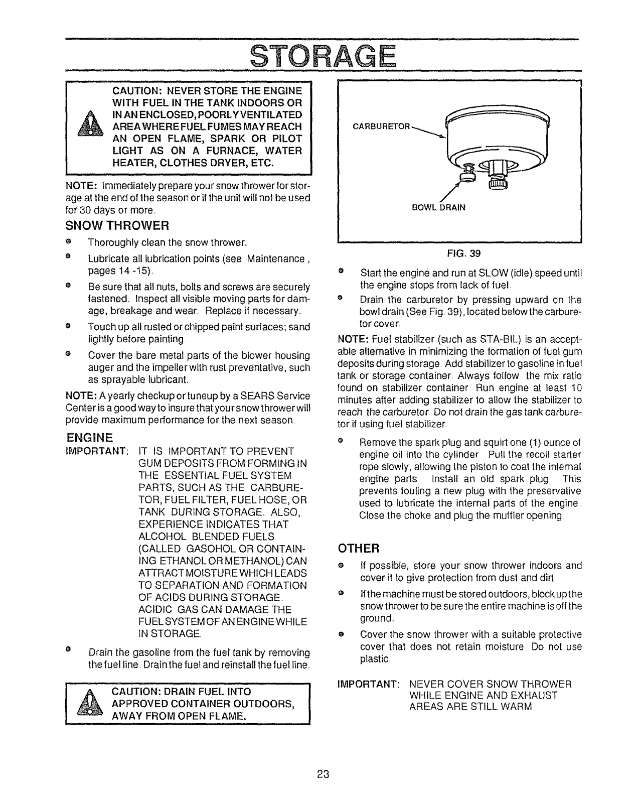
CAUTION: NEVER STORE THE ENGINE
WITH FUEL IN THE TANK INDOORS OR
IN AN ENCLOSED, POORLY VENTILATED
AREAWHERE FUEL FUMES MAY REACH
AN OPEN FLAME, SPARK OR PILOT
LIGHT AS ON A FURNACE, WATER
HEATER, CLOTHES DRYER, ETC.
NOTE: Immediately prepare your snow thrower for stor-
age at the end of the season or if the unit will not be used
for 30 days or more..
SNOW THROWER
e Thoroughly clean the snow thrower..
®Lubricate all lubrication points (see Maintenance,
pages 14-15).
e Be sure that all nuts, bolts and screws are securely
fastened. Inspect all visible moving parts for dam-
age, breakage and wear.. Replace if necessary..
oTouch up all rusted or chipped paint surtaces; sand
lightly before painting
e Cover the bare metal parts of the blower housing
auger and the impeller with rust preventative, such
as sprayable lubricant..
NOTE: A yearly checkup or tun®up by a SEARS Service
Center is a good way to insure that your snow thrower wilt
provide maximum performance for the next season
ENGINE
IMPORTANT: tT IS IMPORTANT TO PREVENT
GUM DEPOSITS FROM FORMING iN
THE ESSENTIAL FUEL SYSTEM
PARTS, SUCH AS THE CARBURE-
TOR, FUEL FILTER, FUEL HOSE, OR
TANK DURING STORAGE.. ALSO,
EXPERIENCE INDICATES THAT
ALCOHOL BLENDED FUELS
(CALLED GASOHOL OR CONTAIN-
ING ETHANOL OR METHANOL) CAN
ATTRACT MOISTURE WHICH LEADS
TO SEPARATION AND FORMATION
OF ACIDS DURING STORAGE.
ACIDIC GAS CAN DAMAGE THE
FUEL SYSTEM OFAN ENGINE WHILE
IN STORAGE.
Drain the gasoline from the fuel tank by removing
the fuel line. Drain the fuel and reinstall the fuel line..
CAUTION: DRAIN FUEL INTO
APPROVED CONTAINER OUTDOORS,
AWAY FROM OPEN FLAME.
BOWL DRAIN
FIG. 39
• Start the engine and run at SLOW (idle) speed until
the engine stops from lack of fuel.
e Drain the carburetor by pressing upward on the
bowl drain (See Fig. 39), located below the carbure-
tor cover.
NOTE: Fuel stabilizer (such as STA-BIL) is an accept-
able alternative in minimizing the formation of fuel gum
deposits during storage. Add stabilizer to gasoline in fuel
tank or storage container, Always follow the mix ratio
found on stabilizer container Run engine at least I0
minutes after adding stabilizer to allow the stabilizer to
reach the carburetor Do not drain the gas tank carbure-
tor if using fuel stabilizer..
Remove the spark plug and squirt one (I) ounce of
engine oil into the cylinder Pull the recoil starter
rope sfowty, allowing the piston to coat the internal
engine parts Install an old spark plug This
prevents fouling a new plug with the preservative
used to lubricate the internal parts of the engine
Close the choke and plug the muffler opening.
OTHER
e If possible, store your snow thrower indoors and
cover it to give protection from dust and dirt.
e lfthe machine must be stored outdoors, btock up the
snow thrower to be sure the entire machine is off the
ground
o Cover the snow thrower with a suitable protective
cover that does not retain moisture_ Do not use
plastic.
IMPORTANT: NEVER COVER SNOW THROWER
WHILE ENGINE AND EXHAUST
AREAS ARE STILL WARM
23
DATIONS
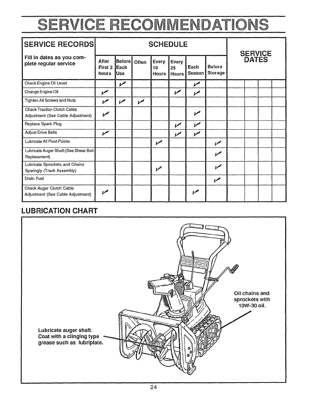
ISERVICE RECORDS SCHEDULE
Fill in dates as you com.
plete regular service
i II,L,, inl IHI I,u_r,t I /11 II .i.i ,_lllll
After Before Often Every Every
First 2 Each 10 25 Each Before
hours Use Hours Hours Season Storage
.HL t I_UI'
Check Engine Oil Level
Change Engine Oil t,f
Tighten All Screws and Nuts t_
Check Traction Clutch Cable
Adjustment {See Cable Adjustment) _t
Replace Spark Plug
Adjust Drive Belts j_
Lubricate All Pivot Points
Lubricate Auger Shaft (See Shear Bolt
Replacement)
Lubricaie Sprockets and Chains
Sparingly (Track Assembly)
Drain Fuel
SERVUCE
DATES
11
v"
Check Auger Clutch Cable
Adjustment {See Cable Adjustment)
t_
=
¢, v"
II
LUBRBCATION CHART
..,,. irl.,
Oil chains and
sprockets with
10W-30 oil.
Lubricate auger shaft,
Coat with a clinging type
grease such as lubriplate.
24
T OU................ G POUNTS
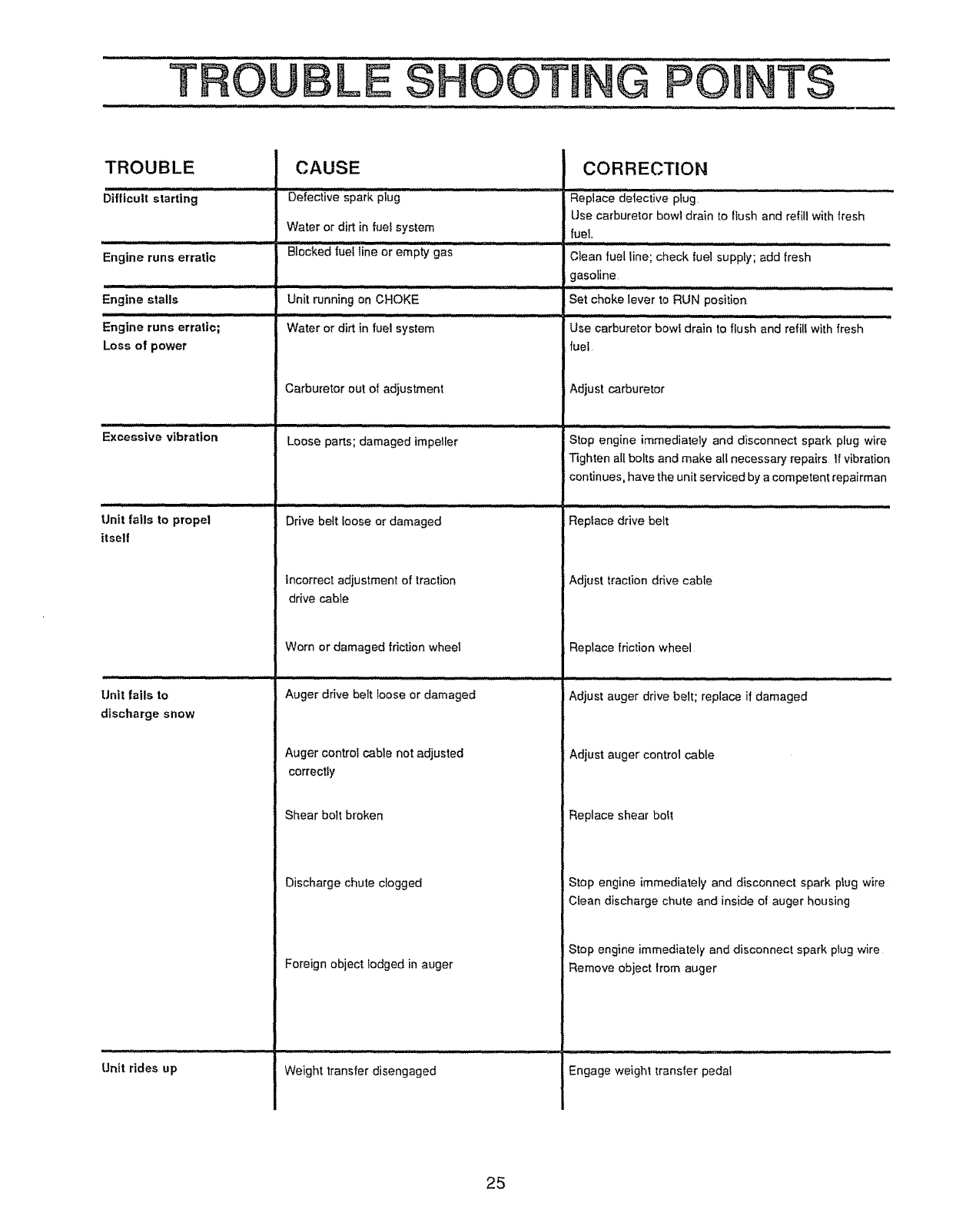
TROUBLE
Engine runs erratic
Engine stalls
Engine runs erratic;
Loss of power
Excessive vibration
Unit fails to propel
itself
Unit fails to
discharge snow
Unit rides up
CAUSE
Defective spark plug
Water or dirt in fuel system
Biocked fuel line 0r emp_ gas
Unit running on CHOKE
Water or dirt in fuel system
Carburetor out of adjustment
Loose parts; damaged impeller
........................:::::................
Drive belt loose or damaged
incorrect adjustment of traction
drive cable
Worn or damaged friction wheel
Auger drive belt loose or damaged
fuel.
Clean fuel line; check fuel supply; add fresh
gasoline
CORRECTION
Replace detective plug
Use carburetor bowl drain to flush and refill with flesh
Set choke lever to RUN position
Use carburetor bowl drain to flush and refill with fresh
fuel
Adjust carburetor
Stop engine immediately and disconnect spark plug wire
Tighten all bolts and make all necessary repairs If vibration
continues, have the unit serviced by a competent repairman
Repiace drive belt
Adjust traction drive cable
Replace friction wheel
i Adjust auger drive belt; replace if damaged
Auger control cable not adjusted
correctly
Shear bolt broken
Adjust auger control cable
Replace shear bolt
Stop engine immediately and disconnect spark plug wire
Clean discharge chute and inside of auger housing
Discharge chute clogged
Foreign object lodged in auger
Stop engine immediately and disconnect spark plug wire
Remove object from auger
Weight transfer disengaged Engage weight transfer pedal
25
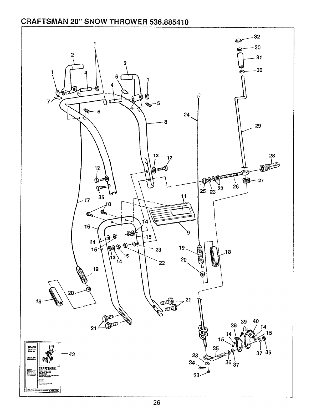
CRAFTSMAN 20" SNOW THROWER 536.885410
1
2
4
12
35
14
15
19
3
15
14
3 12
22
24
19
20
/
/
29
28
21
39 40
38 14
t4 _15
_42
37
37 36
26
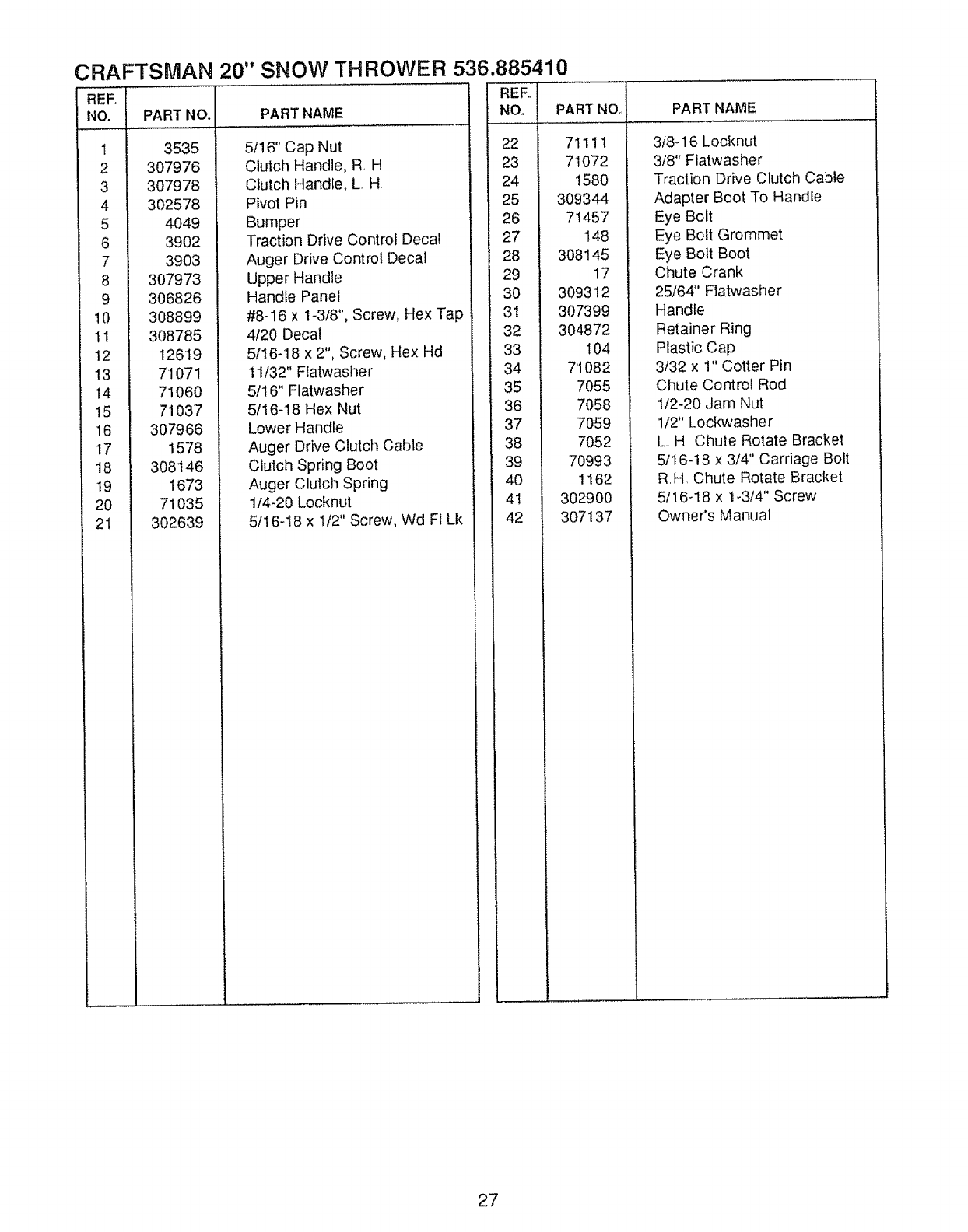
CRAFTSMAN 20" SNOW THROWER 536.885410
REF,,
NO, PART NO.
7
8
9
10
11
12
13
14
15
16
17
18
19
2O
21
3535
307976
307978
302578
4049
3902
3903
307973
306826
308899
308785
126I9
71071
71060
71037
307966
1578
308146
1673
71035
302639
PART NAME
5/16" Cap Nut
Clutch Handle, R, H
Clutch Handle, L H
Pivot Pin
Bumper
Traction Drive Control Decal
Auger Drive Control Decal
Upper Handle
Handle Panel
#8-16 x I-3/8", Screw, Hex Tap
4/20 Decal
5/16-18 x 2", Screw, Hex Hd
t 1/32" Flatwasher
5/16" Flatwasher
5/16-18 Hex Nut
Lower Handle
Auger Drive Clutch Cable
Clutch Spring Boot
Auger Clutch Spring
1/4-20 Locknut
5/16-!8 x 1/2" Screw, Wd F! Lk
PART NQ,
71111
71072
1580
309344
71457
148
308145
17
309312
307399
304872
104
7'1082
7055
7058
7059
7052
70993
1162
302900
3O7137
PART NAME
3/8-16 Locknut
3/8" Flatwasher
Traction Drive Clutch Cable
Adapter Boot To Handle
Eye Boft
Eye Bolt Grommet
Eye Bolt Boot
Chute Crank
25/64" Flatwasher
Handle
Retainer Ring
Plastic Cap
3/32 x 1" Cotter Pin
Chute Control Rod
1/2-20 Jam Nut
'1/2" Lockwasher
L H Chute Rotate Bracket
5/16-18 x 3/4" Carriage Bolt
R,H, Chute Rotate Bracket
5/16_18 x 1-3/4" Screw
Qwner's Manual
27
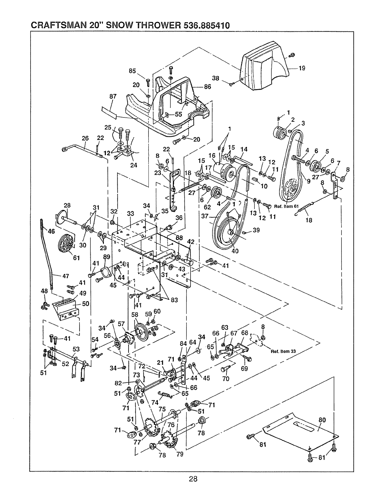
CRAFTSMAN 20" SNOW THROWER 536.885410
28
61
31
87
i
33
22
38
16
15
62
40
14
_f12 3
ReL Item 78_
12 11 18
39
51
47
53
41
58 59 6O
83
34
84 64
63
.>
8
68
7O
71
51
78 79
28
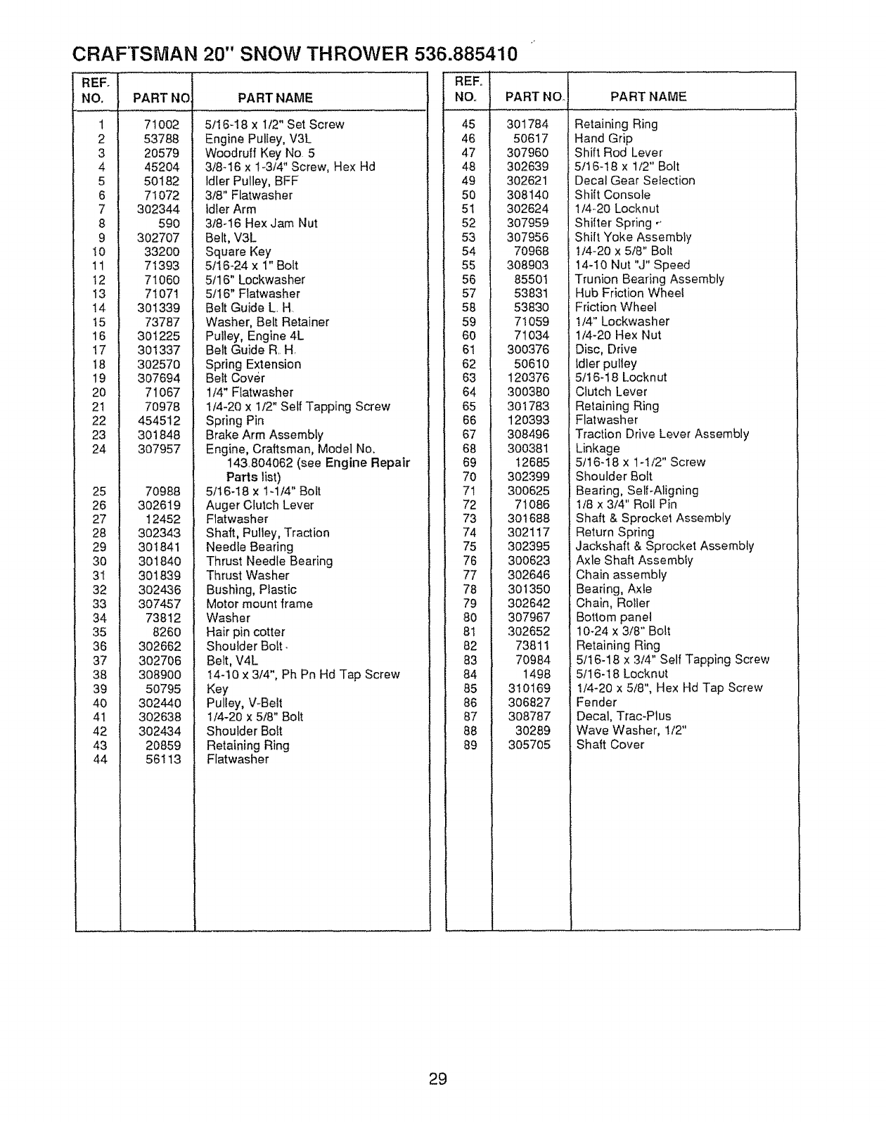
CRAFTSMAN 20" SNOW THROWER 536.885410
REF.
NO. PART NO
1 71OO2
2 53788
3 20579
4 45204
5 50182
6 71072
7 302344
8 590
9 302707
t0 3320O
11 71393
t2 71060
13 71071
14 301339
15 73787
16 301225
!7 301337
t8 302570
19 307694
20 71067
21 70978
22 454512
23 301848
24 307957
25 7O988
26 3O2619
27 12452
28 3O2343
29 3O1841
30 3O184O
3I 301839
32 302436
33 307457
34 73812
35 8260
36 302662
37 302706
38 308900
39 50795
40 302440
41 302638
42 302434
43 20859
44 56113
PART NAME
5116-18 x I/2" Set Screw
Engine Pulley, V3L
Woodruff Key No 5
3/8-i6 x 1-3/4" Screv, Hex Hd
Idler Pulley, BFF
3/8" Flatwasher
idler Arm
3/8-16 Hex Jam Nut
Belt, V3L
Square Key
5/I 6-24 x 1" Bolt
5/16" Lockwasher
5/t6" Flatwasher
Belt Guide L H
Washer, Belt RetainE
Pulley, Engine 4L
Belt Guide R H,
Spring Extension
Belt Cover
1/4" Ffatwasher
t/4-20 x 1/2" Self Tapping Screw
Spring Pin
Brake Arm Assembly
Engine, Craftsman, Model No.
143.804062 (see Engine Repair
Parts list)
5/t6-I8 x lq/4" Bolt
Auger Clutch Lever
Flatwasher
Shaft, Pulley, Tractio
Needle Bearing
Thrust Needle Bearir_g
Thrust Washer
Bushing, Ptastic
Motor mount frame
Washer
Hair pin cotter
Shoulder Bolt.
Belt, V4L
14-t0 x 3/4", Ph Pn Hd Tap Screw
Key
Pulley, V-Belt
I/4-20 x 5/8" Bolt
Shoulder Bolt
Retaining Ring
Flatwasher
REFo
NO., PART NO. PART NAME
45
46
47
48
49
50
51
52
53
54
55
56
57
58
59
60
6t
62
63
64
65
66
67
68
69
70
71
72
73
74
75
76
77
78
79
80
8I
82
83
84
85
86
87
88
89
3O1784
5O617
3O7960
302639
302621
30814O
3O2624
307959
307956
70968
308903
85501
53831
53830
71059
71034
300376
50610
120376
300380
301783
120393
308496
300381
12685
302399
300625
71086
301688
302117
302395
300623
302646
301350
302642
307967
302652
73811
70984
1498
310169
306827
308787
30289
305705
Retaining Ring
Hand Grip
Shift Rod Lever
5/t 6-18 x 1/2" Bolt
Decal Gear Selection
Shilt Console
1/4-20 Locknut
Shilter Spring r.
Shift Yoke Assembly
!/4-20 x 5/8" Bolt
14-10 Nut "J" Speed
Trunion Bearing Assembly
Hub Friction Wheel
Friction Wheel
t/4" Lockwasher
1/4-20 Hex Nut
Disc, Drive
Idler pulley
5/16-18 Locknut
Clutch Lever
Retaining Ring
Flatwasher
Traction Drive Lever Assembly
Linkage
5/16-18 x 1-1/2" Screw
Shoulder Bolt
Bearing, Self-Aligning
1/8 x 3/4" Roll Pin
Shaft & Sprocket Assembly
Return Spring
Jackshaft & Sprocket Assembly
Axle Shah Assembfy
Chain assembly
Bearing, Axle
Chain, Roller
Bottom panel
10-24 x 3/8" Bolt
Retaining Ring
5/t 6-18 x 3/4" Self Tapping Screw
5116-18 Locknut
I/4-20 x 5/8", Hex Hd Tap Screw
Fender
Decal, Trac-Plus
Wave Washer, 1/2"
Shaft Cover
29
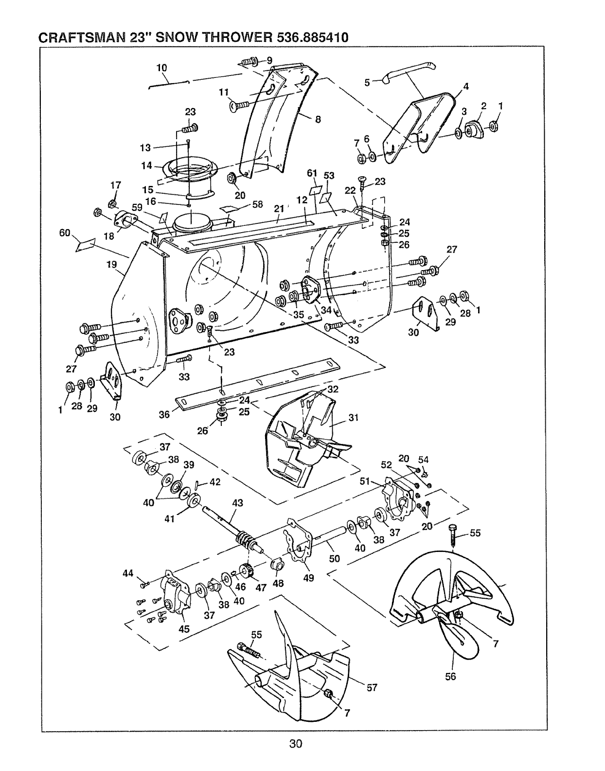
CRAFTSMAN 23" SNOW THROWER 536.885410
23
5
\
7
4
2 1
27
17
18
19
3O
15
21
"\
33
36
41
61 53
24
27
35 o
3O 29
7
3O
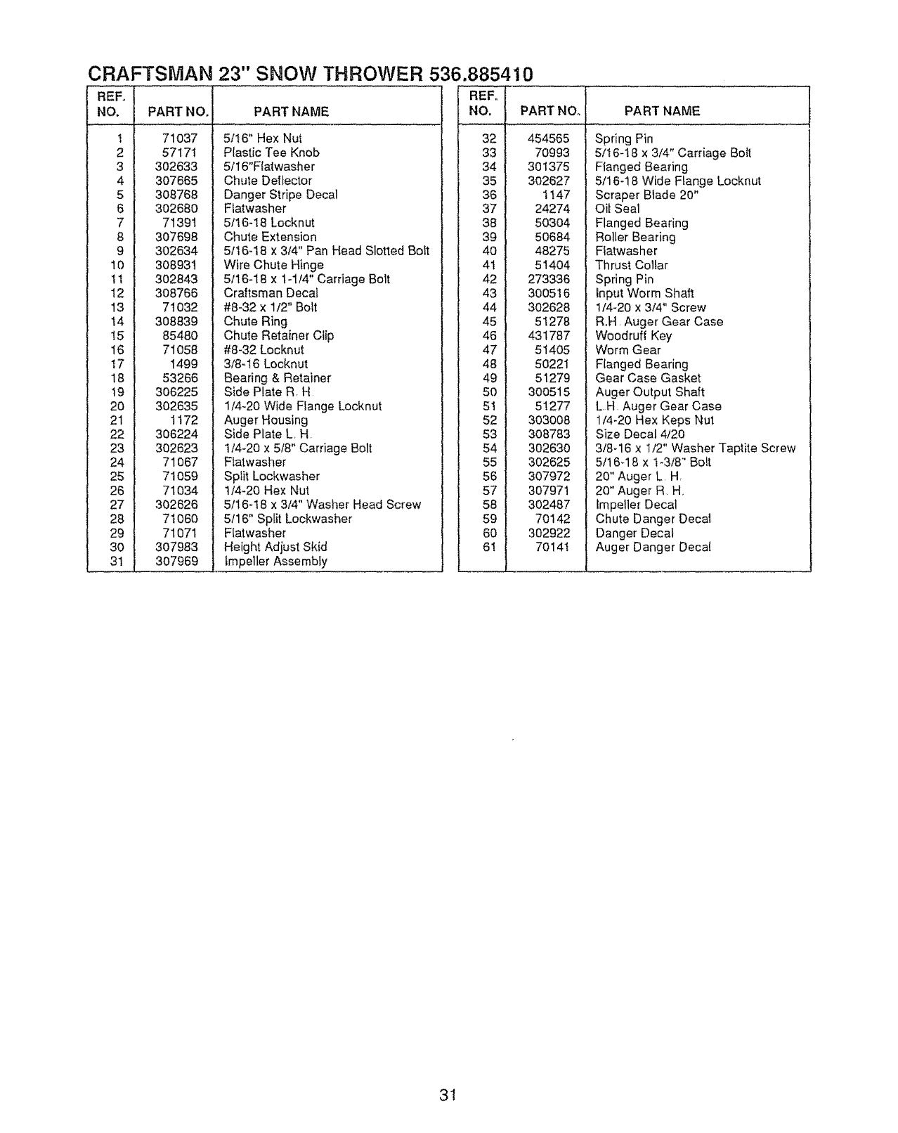
CRAFTSMAN 23" SNOW THROWER 536.885410
REFo
NO.
1
2
3
4
5
6
7
8
9
10
i1
12
13
t4
15
I6
!7
18
t9
2O
21
22
23
24
25
26
27
28
29
3O
3t
PART NO. PART NAME
71037 5/16" Hex Nut
57171 Plastic Tee Knob
302633 5/16"F{atwasher
307665 Chute Deflector
308768 Danger Stripe Decal
302680 Flatwasher
7139t 5/16-18 Lockn ut
307698 Chute Extension
302634 5/16-18 x 3/4" Pan Head Slotted Bolt
308931 Wire Chute Hinge
302843 5116-18 x 1-1/4" Carriage Bolt
308766 Craftsman Decal
71032 #8-32 x 1/2" Bolt
308839 Chute Ring
85480 Chute Retainer Clip
71058 #8-32 Locknut
I499 3/8-!6 Locknut
53266 Bearing & Retainer
306225 Side Plate R H
302635 1/4-20 Wide FLange Locknut
t t72 Auger Housing
306224 Side Plate L H
302623 t/4-20 x 5/8" Carriage Bolt
71067 Flatwasher
71059 Split Lockwasher
71034 t/4-20 Hex Nut
302626 5/16-t8 x 3/4" Washer Head Screw
7I 060 5/16" Split Lockwasher
71071 Flatwasher
307983 Height Adjust Skid
307969 Impeller Assembly
.... 32
33
34
35
36
37
38
39
4O
4t
42
43
44
45
46
47
48
49
50
51
52
53
54
55
56
57
58
59
60
61
PART NO.
454565
70993
301375
302627
1t47
24274
50304
50684
48275
51404
273336
30O516
302628
51278
431787
514O5
5O221
51279
300515
51277
303008
3O8783
302630
302625
307972
307971
302487
70142
302922
70141
PART NAME
Spring Pin
5/t 6-! 8 x 3/4" Carriage Bo{t
Flanged Bearing
5/16-! 8 Wide Flange Locknut
Scraper Blade 20"
Oit Seal
Flanged Bearing
Roller Bearing
Ffatwasher
Thrust Collar
Spring Pin
Input Worm Shaft
1/4-20 x 3/4" Screw
R.H Auger Gear Case
Woodruff Key
Worm Gear
Flanged Bearing
Gear Case Gasket
Auger Output Shaft
LH Auger Gear Case
1/4-20 Hex Keps Nut
Size Decal 4/20
3/8-16 x !/2" Washer Taptite Screw
5/16-18 x t-3/8" Bolt
20" Auger L H
20" Auger R H
tmpeller Decal
Chute Danger Decal
Danger Decal
Auger Danger Decal
31
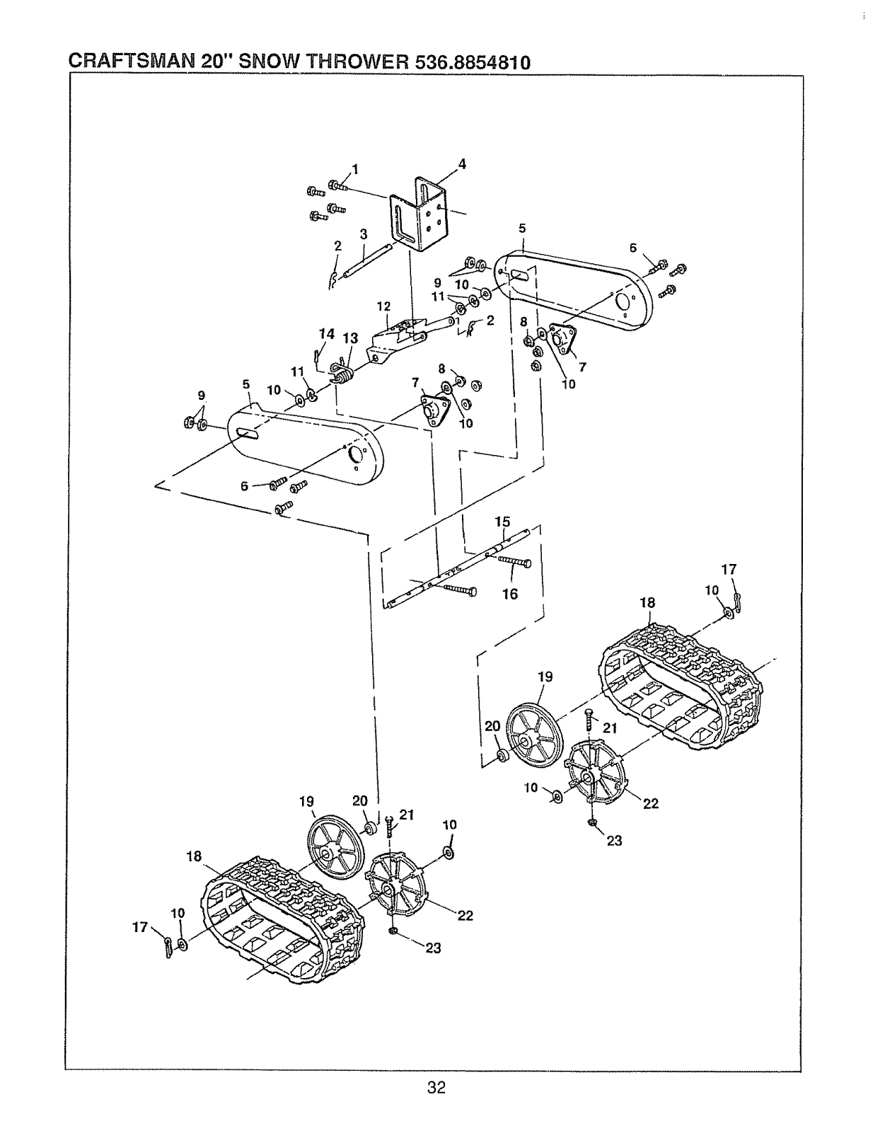
CRAFTSMAN 20" SNOW THROWER 536.8854810
9
18
11
5
14
19 20
12
,_21 _o k23
32
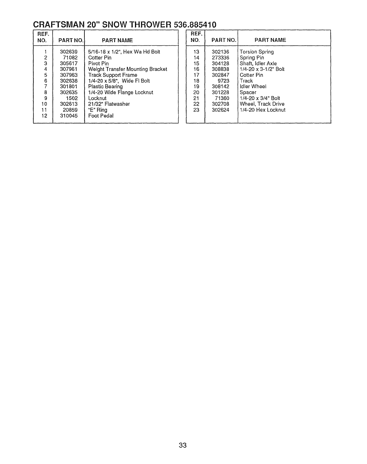
CRAFTSMAN 20" SNOW THROWER 536.885410
REFo
NO.
1
2
3
4
5
6
7
8
9
10
tl
t2
PART NO
3O2639
71082
305617
307961
307963
302638
301801
302635
1502
302613
20859
31O045
PART NAME
5/16-t8 x 1/2", Hex Wa Hd Bolt
Cotter Pin
Pivot Pin
Weight Transfer Mounting Bracket
Track Support Frame
1/4-20 x 5/8", Wide FI Boft
Plastic Bearing
1/4-20 Wide Range Locknut
Locknut
21/32" Flatwasher
"E" Ring
Foot Pedal
REF. 1
NO, I
13 J
: 14 I
15 1
16 1
17 l
18 1
19 1
20 I
21 I
22
23 I
PART NOo
302136
273336
304128
308838
3O2847
9723
3O8142
30!228
7136O
302708
3O2624
PART NAME
Torsion Spring
Spring Pin
Shaft, Idler Axle
1/4-20 x 3-112" Bolt
Cotter Pin
Track
Idler Wheel
Spacer
1/4-20 x 3!4" Bolt
Wheel, Track Drive
1/4-20 Hex Locknut
33
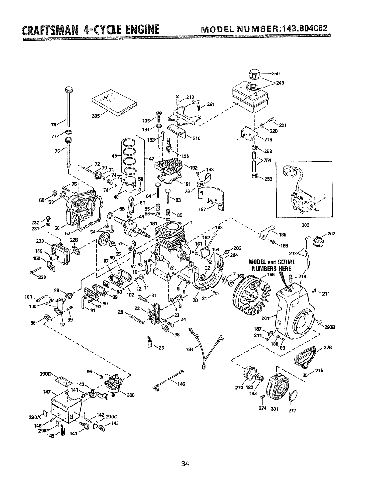
(P_FTSMAH4=(:Y(L[[N6iH[ MODELNUMBER:143.804062
,218
250
249
34
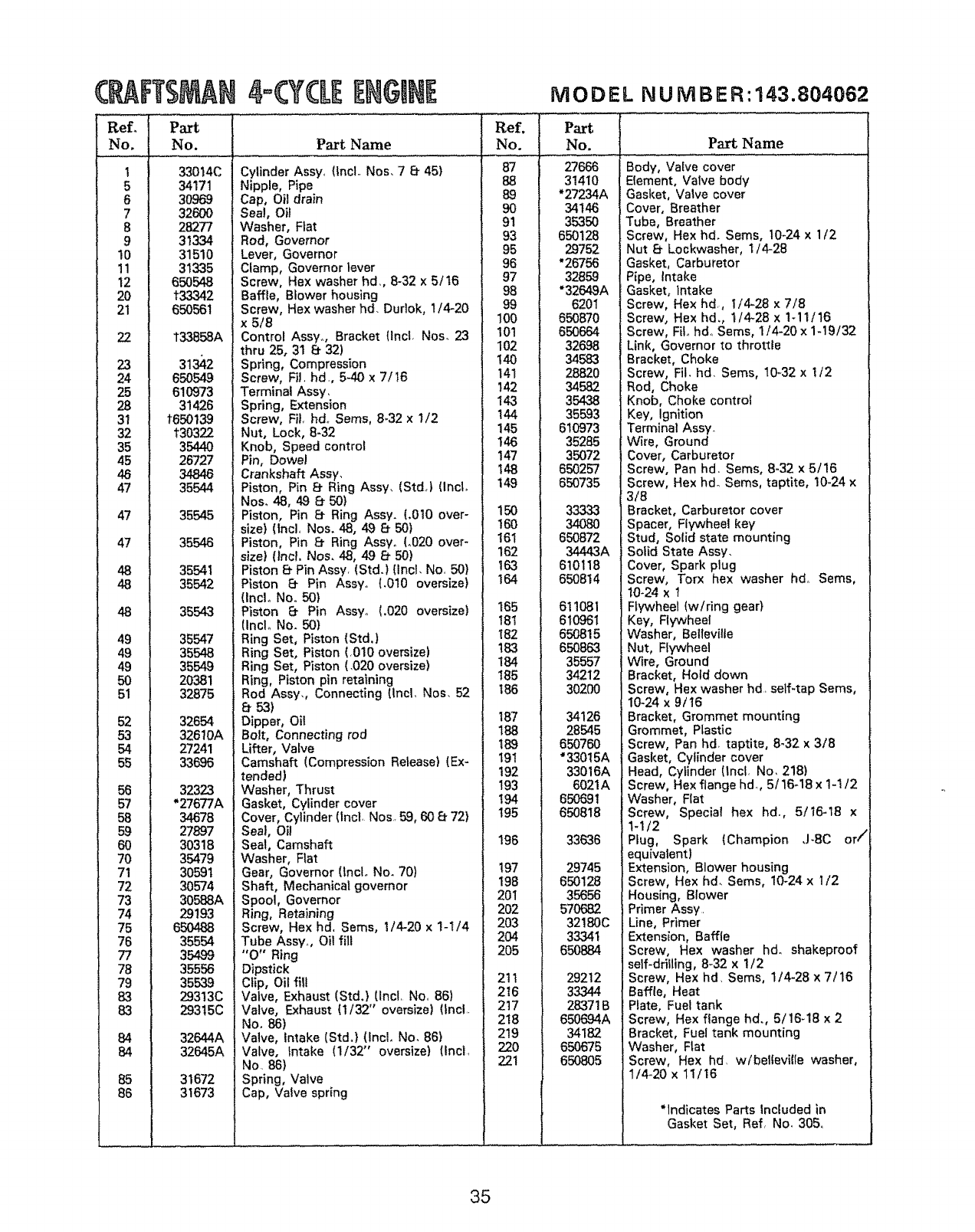
C rTSMAN
Ref_ Part
No. No.
1
5
6
7
8
9
10
11
12
2O
21
22
23
24
25
28
31
32
35
45
46
47
47
47
48
48
48
49
49
49
50
51
52
53
54
55
56
57
58
59
6O
70
71
72
73
74
75
76
77
78
79
83
83
84
84 i
85
86 i
_._J
4o(yCLEENGINE
33014C
34171
30969
32600
28277
31334
31510
31335
650548
133342
650561
133858A
31 2
650549
610973
31426
1650139
t30322
35440
26727
34846
35544
35545
35546
35541
35542
35543
35547
35548
35549
20381
32875
32654
32610A
27241
33696
32323
"27677A
34678
27897
30318
35479
30591
30574
30588A
29193
650488
35554
35499
35556
35539
29313C
29315C
32644A
32645A
31672
31673
Part Name
Cylinder Assy, (tncL Nos. 7 8- 45)
Nipple, Pipe
Cap, Oil drain
Seal, Oil
Washer, Fiat
Rod, Governor
Lever, Governor
Clamp, Governor lever
Screw, Hex washer hd,, 8-32 x 5/16
Baffle, Blower housing
Screw, Hex washer hd. Dudok, 1/4-20
x 5/8
Control Assyo, Bracket (IncL Nos. 23
thru 25, 31 e 32)
Spring, Compression
Screw, Fil, hd., 5-40 x 7/_6
Terminal Assy,
Spring, Extension
Screw, Fit. haloSems, 8-32 x 1/2
Nut, Lock, 8-32
Knob, Speed control
Pin, Dowel
Crankshaft Assy.
Piston, Pin 8, Ring Assy, (StdJ (lncL
Nos, 48, 49 8- 50)
Piston, Pin 8_ Ring Assy. (.010 over-
size) (lncl, Nos. 48, 49 850)
Piston, Pin 8` Ring Assyo (.020 over-
size) (Incl, Nos. 48, 49 8` 50)
Piston Ef Pin Assy, (Std.) (Incl. No, 50)
Piston 8` Pin Assyo (.010 oversize)
(IncL No.. 50)
Piston 8` Pin Assy° (.020 oversize)
{Inclo No. 50)
Ring Set, Piston {Std.)
Ring Set, Piston (O10 oversize)
Ring Set, Piston (,020 oversize)
Ring, Piston pin retaining
Rod Assy,, Connecting (Incl., Nos. 52
e 53)
Dipper, Oil
Bolt, Connecting rod
Lifter, Valve
Camshaft [Compression Release) (Ex-
tended)
Washer, Thrust
Gasket, Cylinder cover
Cover, Cylinder (lncl, Nos 59, 60 &_72)
Seal, Oil
Seal, Camshaft
Washer, Flat
Gear, Governor {Inclo No. 70)
Shaft, Mechanical governor
Spool, Governor
Ring, Retaining
Screw, Hex hd. Seres, I/4-20 x 1-1/4
Tube Assyo, Oil fill
"O" Ring
Dipstick
Clip, Oil lilt
Valve, Exhaust (Std.} [Incl. No, 86)
Valve, Exhaust (1/32" oversize) (lncl..
No. 86)
Valve, Intake (Std.) (IncL No. 86)
Valve, Intake (1/32" oversize) (Incl,
No. 86)
Spring, Valve
Cap, Valve spring
Ref.
No.
87
88
89
9O
91
93
95
96
97
98
99
100
101
102
!40
141
142
143
!44
145
146
147
148
149
150
160
161
162
163
!64
165
181
182
183
184
185
186
187
188
189
191
192
193
194
195
196
t97
198
201
202
203
204
2O5
211
216
2t7
218
219
22O
221
i
i
..................i
MODEL NU NIB ER:143.804062
Part Name
Part
No,
27666
31410
"27234A
34146
35350
650128
29752
"26756
32859
"32649A
6201
650870
650664
32698
34583
2882O
34582
35438
35593
610973
35285
35072
650257
650735
33333
34080
650872
34443A
610118
650814
611081
610961
650815
650863
35557
34212
30200
34126
28545
650760
"33015A
33016A
6021A
65O691
650818
33636
29745
650128
35656
57O682
32!80C
33341
65O884
29212
33344
2837! B
650694A
34182
650675
650805
Body, Valve cover
Element, Valve body
Gasket, Valve cover
Cover, Breather
Tube, Breather
Screw, Hex hdo Sems, 10_24x 1/2
Nut 8- Lockwasher, 1/4-28
Gasket, Carburetor
Pipe, Intake
Gasket, Intake
Screw, Hex hd, 1/4-28 x 7/8
Screw, Hex hd,, 1/4_28 x 1-11/16
Screw, FiL hd, Seres, 1/4-20 x %19/32
Link, Governor to throttle
Bracket, Choke
Screw, Fil, hd, Seres, 10-32 x I/2
Rod, Choke
Knob, Choke control
Key, Ignition
Terminal Assy.
Wire, Ground
Cover, Carburetor
Screw, Pan hd. Seres, 8-32 x 5/t6
Screw, Hex hdo Seres, taptite, 10-24 x
3/8
Bracket, Carburetor cover
Spacer, Flywheel key
Stud, Solid state mounting
Solid State Assy.
Cover, Spark plug
Screw, Torx hex washer hd, Sums,
10-24 x 1
Rywheet (w/ring gear)
Key, Flywheel
Washer, Beltevilie
Nut, Flywheel
Wire, Ground
Bracket, Hold down
Screw, Hex washer hd, self*tap Sums,
10-24 x 9/16
Bracket, Grommet mounting
Grommet, Plastic
Screw, Pan hd taptite, 8_32 x 3/8
Gasket, Cylinder cover
Head, CyLinder (Incl, No, 218)
Screw, Hex flange hd., 5/16-18 x 1-1/2
Washer, Flat
Screw, Special hex hd., 5/16-18 x
1-1/2
Piug, Spark {Champion J-BC or/"
equivalent)
Extension, Blower housing
Screw, Hex hd. Sums, 10-24 x I/2
Housing, Blower
Primer Assy.
Line, Primer
Extension, Baffle
Screw, Hex washer hdo shakeproof
self-drilling, 8-32 x 1/2
Screw, Hex hd, Sums, 1/4-28 x 7/16
Baffle, Heat
Piate, Fuel tank
Screw, Hex flange hd., 5/16q8 x 2
Bracket, Fuel tank mounting
Washer, Rat
Screw, Hex hd. w/beIIeville washer,
1/4o20 x 11/16
*Indicates Parts Included in
Gasket Set, Ref, No. 305,
35
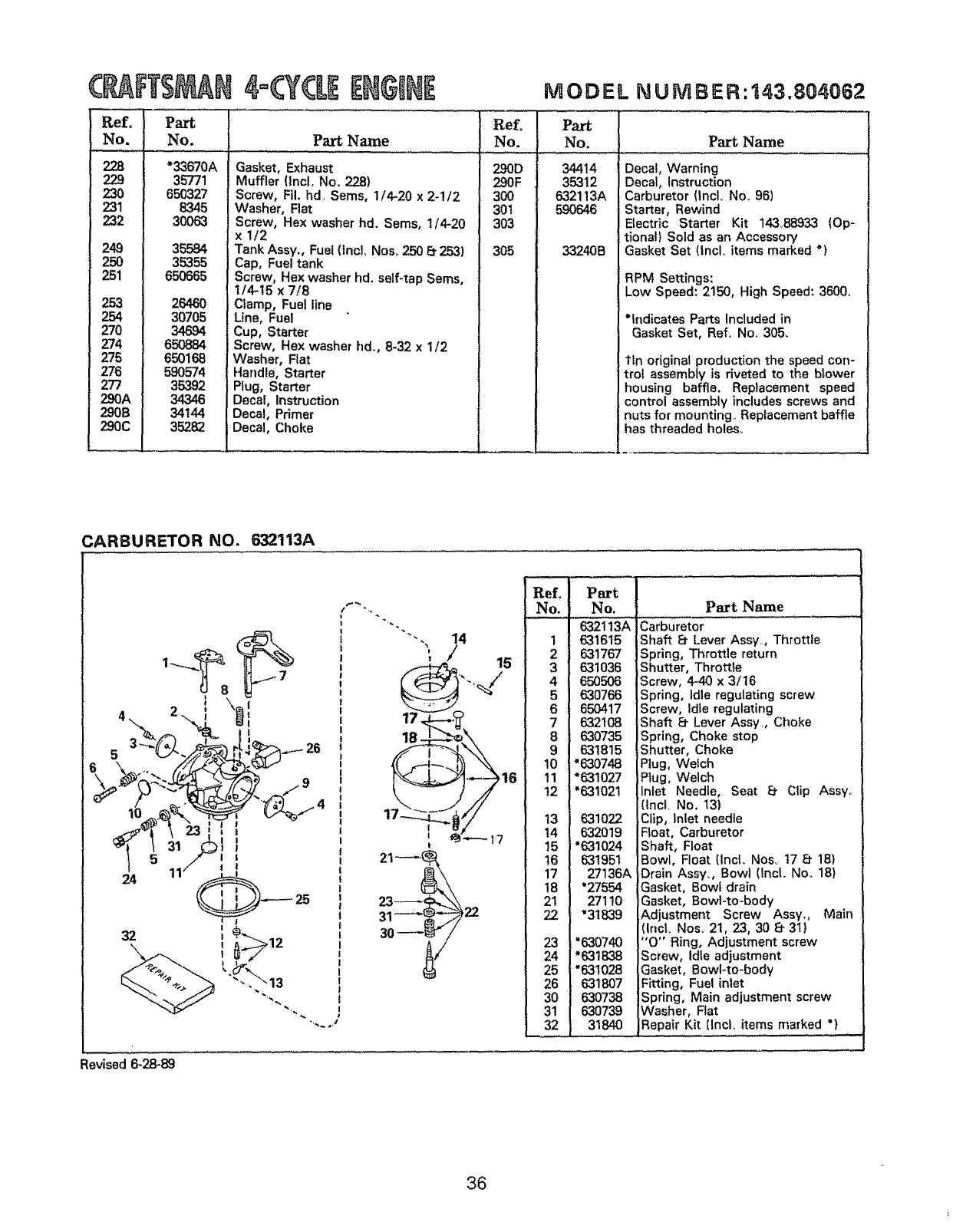
C FT$ N
ReL'
No, ! No.
35771
_2 I 650327300638345
249 I35584
250 35355
251 I 650665
30705
270 34694
274 I 65O884
275 650168
276 590574
277 35392
290A1 34346
290B J 34144
290C 35282
4=G'CLEE GmN
Part Name
MODEL NUNIBER:143.804062
Ref. Part
No. No Part Name
290D 34414
290F 35312
300 632113A
301 590646
303
305 33240B
Gasket, :haust
Muffler =cL No. 228)
Screw, Fil. hd, Seres, 1/4-20 x 2-1/2
Washer, ]at
Screw, =xwasher hd. Seres. 1/4-20
x1/2
Tank Ass_., Fuel (Incl, Nos° 250 8. 253)
Cap, F1 tank
Screw, x washer hd, self-tap Sems,
1/4-15 x 7/8
Ctamp, Fuel line
Line, Fuel
Cup, Starter
Screw, x washer hd. 8-32 x 1/2
Washer, at
Handle, S arter
Plug, Starter
Decal, ruction
Decal, _er
Decal, ,ke
Decal, Warning
Decal, instruction
Carbure (Incl. No. 96)
Starter, Rewind
Electric Starter Kit 14&88933 {Op-
lionel) Sold as an Accessory
Gasket Set (Incl. items marked "}
RPM Settings:
Low Speed: 2150, High Speed: 3600.
*lndicat Parts Included in
Gasket Set, Ref. No. 305.
tin orig_ production the speed con-
trol ass_ y is riveted to the blower
housing baffle. Replacement speed
control assembly includes screws and
nuts for mounting. Replacement baffle
has threaded holes.
CARBURETOR NO. 632113A
4.. "-..Lf!ll
24 O_ 25
32
I
I
I
1
"'"".,, 14
_, 15
1__7
t
Ref.
No. Part Name
Part
No.
632t 13A
1 631615
2 631767
3 631036
4 650506
5630766
6 65PA17
7 632108
8630735
9631815
10 "630748
11 *631027
12 "631021
13 631022
14 632O19
15 *631024
16 631951
17 27136A
t8 "27554
21 27110
22 "31839
23 "630740
24 *631838
25 "631028
26 631807
30 630738
31 630739
32 31840
Carburetor
Shaft 8 Lever Assy., Throttle
Spring, Throttle return
Shutter, Throttle
Screw, 4-40 x 3/16
Spring, idle regulating screw
Screw, Idle regulating
Shaft E_Lever Assy,, Choke
Spring, Choke stop
Shutter, Choke
Plug, Weich
Plug, Welch
Inlet Needle, Seat _ Clip Assy..
(lncL No. 13)
Clip, Inlet needle
Float, Carburetor
Shaft, Float
Bowl, Float (lncl. Nos_ t7 8 18)
Drain Assy., Bowl (Incl. Noo 18}
Gasket, Bowt drain
Gasket, Bowl-to-body
Adjustment Screw Assy,, Main
(IncL Nos_ 21, 23, 30 Ef 311
"O" Ring, Adjustment screw
Screw, Idle adjustment
Gasket, Bowl*to-body
Fitting, Fuel inlet
Spring, Main adjustment screw
Washer, Rat
Repair Kit (Incl. items marked *)
Revised 6-28-89
36
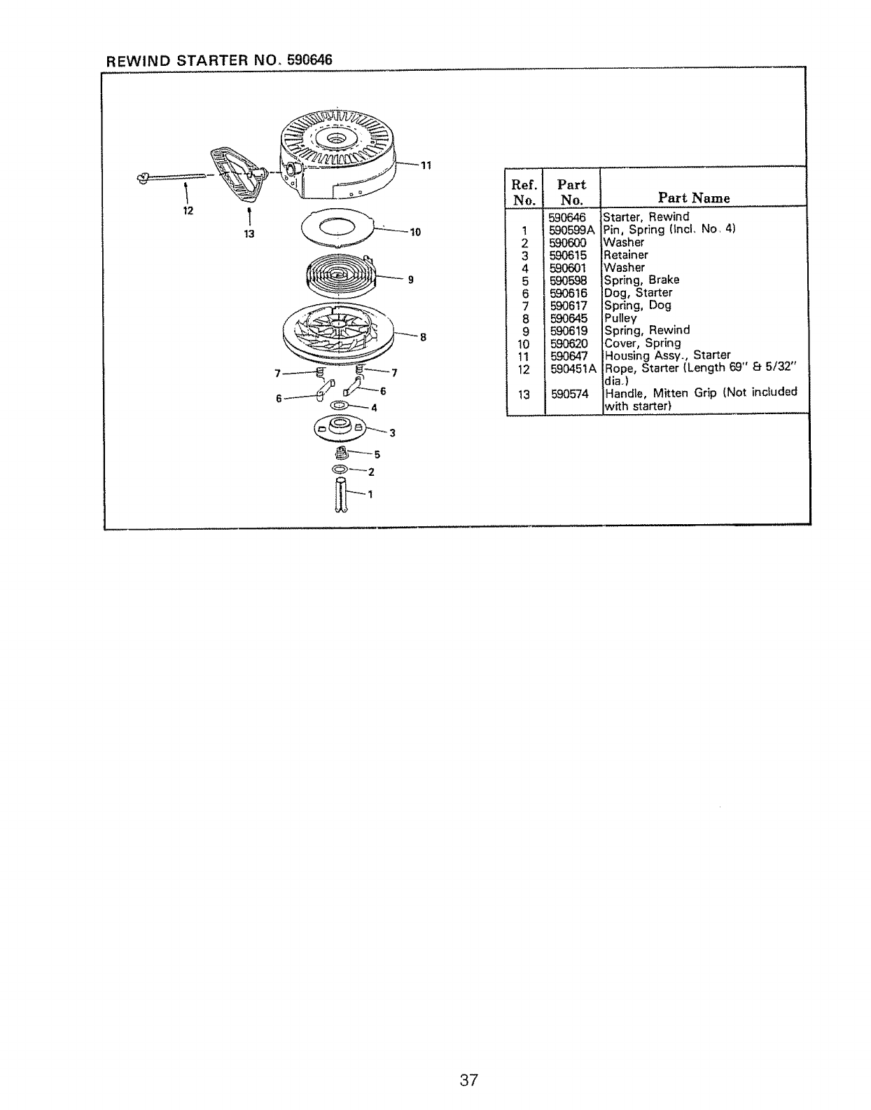
REWIND STARTER NOr 590646
12
13
...... ......................,,L
Ref. Part
No. No.
t
2
3
4
5
6
7
8
9
10
11
t2
13
Part Name ]
590646 Starter, Rewind
590599A Pin, Spring (tncl, No. 4)
590600 Washer
590615 Retainer
590601 Washer
590598 Spring, Brake
590616 Dog, Starter
590617 Spring, Dog
590645 Pulley
590619 Spring, Rewind
590620 Cover, Spring
5.90647 Housing Assyo, Starter
590451A iRope, Starter (Length 69" 8 5/32"
dia,)
590574 Handle, Mitten Grip [Not included
with starter}
37
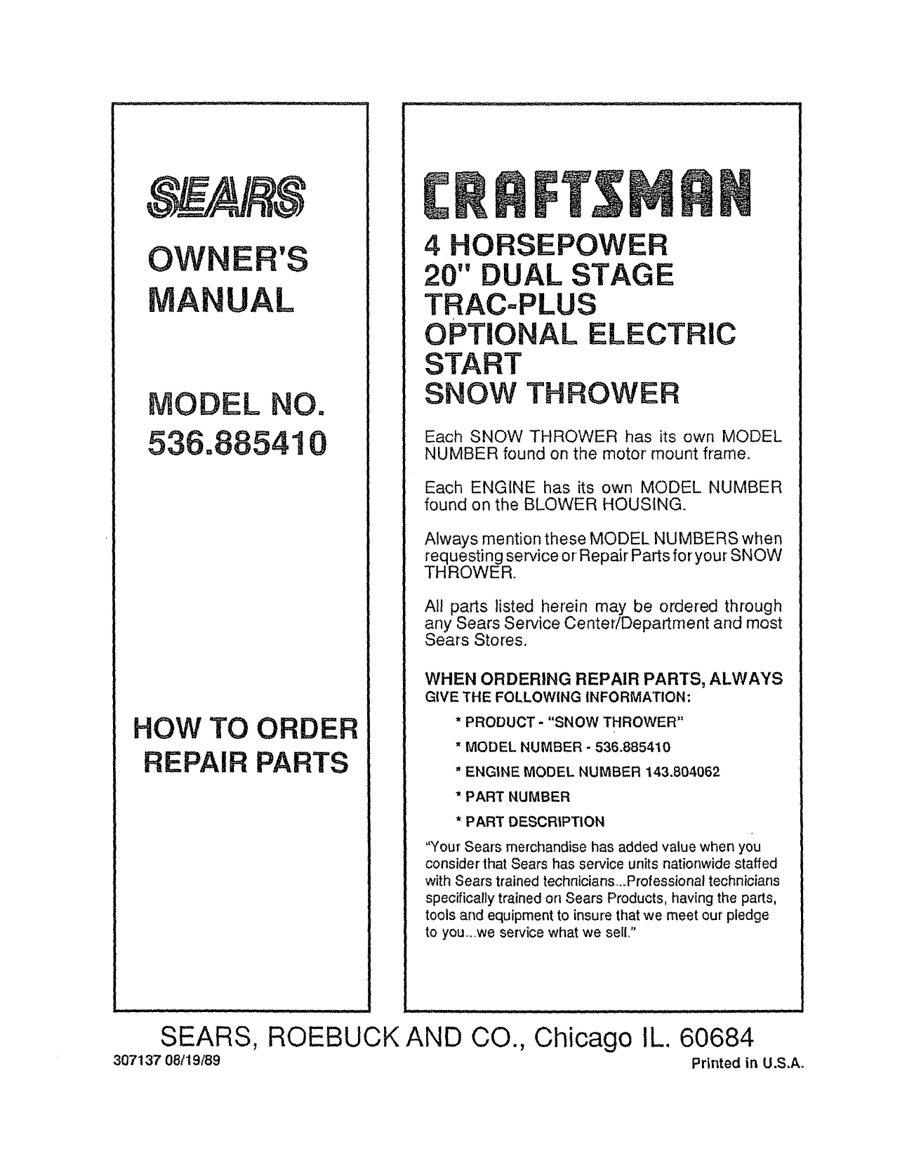
OWNER'S
UAL
MODEL NO.
536°885410
HOW TO ORDER
REPAIR PARTS
C T$
4 HORSEPOWER
20" DUAL STAGE
TRAC..PLUS
OPTIONAL ELECTRIC
START
SNOW THROWER
Each SNOW THROWER has its own MODEL
NUMBER found on the motor mount frame.
Each ENGINE has its own MODEL NUMBER
found on the BLOWER HOUSING.
Always mention these MODEL NUMBERS when
requesting service or Repair Parts foryour SNOW
THROWER.
All parts listed herein may be ordered through
any Sears Service Center/Department and most
Sears Stores,
WHEN ORDERING REPAIR PAR'TS, ALWAYS
GIVE THE FOLLOWING INFORMATION:
*PRODUCT - "SNOW THROWER"
"MODEL NUMBER - 536.885410
*ENGINE MODEL NUMBER 143.804062
"PART NUMBER
* PART DESCRIPTION
"Your Sears merchandise has added value whenyou
consider that Sears has service units nationwide staffed
with Sears trained technicians,,.,Professional technicians
specifically trained on Sears Products, having the parts,
tools and equipment to insure that we meet our pledge
to you,_..,weservice what we sell,"
......... :. ::: 1, q,UH nl rut ii /u
SEARS, ROEBUCK AND
307137 08/19/89 CO., Chicago IL. 60684
Printed in U.S.Ao
