Sears 917 25254 Users Manual
917252540 917252540 CRAFTSMAN LAWN TRACTOR - Manuals and Guides L0809027 View the owners manual for your CRAFTSMAN LAWN TRACTOR #917252540. Home:Lawn & Garden Parts:Craftsman Parts:Craftsman LAWN TRACTOR Manual
CRAFTSMAN Lawn, Tractor Manual L0809027 CRAFTSMAN Lawn, Tractor Owner's Manual, CRAFTSMAN Lawn, Tractor installation guides
!! Sears-21 Sears Lawn Mower Manuals - Lawn Mower Manuals – The Best Lawn Mower Manuals Collection
917.25254 to the manual a9152932-7f39-4c0e-92e0-e4c1bff5f37e
2015-02-05
: Sears Sears-917-25254-Users-Manual-399131 sears-917-25254-users-manual-399131 sears pdf
Open the PDF directly: View PDF ![]() .
.
Page Count: 56
_9
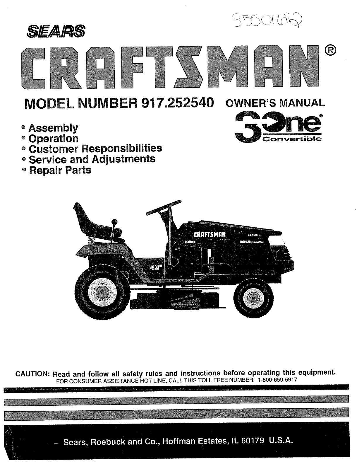
®
MODEL 917.252540
°Assembly
°Operation
oCustomer Responsibilities
oService and Adjustments
o Repair Parts
OWNER'S MANUAL
Convertible
CAUTION: Read and follow all safety rules and instructions before operating this equipment.
FOR CONSUMER ASSISTANCE HOT LINE, CALL THIS TOLL FREE NUMBER: 1-800-659-5917
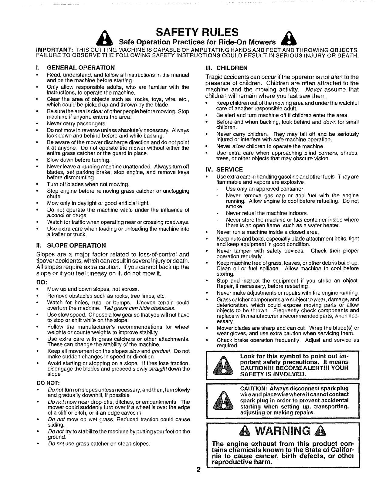
SAFETY RULES
Safe Operation Practices for Ride-On Mowers
IMPORTANT: THIS CUTTING MACHINE IS CAPABLE OF AMPUTATING HANDS AND FEET AND THROWING OBJECTS
FAILURE TO OBSERVE THE FOLLOWING SAFETY INSTRUCTIONS COULD RESULT IN SERIOUS INJURY OR DEATH.
1. GENERAL OPERATION
•Read, understand, and follow al! instructions in the manual
and on the machine before starting
-Only allow responsible adults, who are familiar with the
instructions, to operate the machine.
•Clear the area of objects such as rocks, toys, wire, etc,
which could be picked up and thrown by the blade.
• Be sure the area is clear of other people before mowing, Stop
machine if anyone enters the area°
• Never carry passengers.
•Do not mow in reverse unless absolutely necessary. Always
look down and behind before and while backing.
• Be aware of the mower discharge direction and do not point
it at anyone. Do not operate the mower •without either the
entire grass catcher or the guard in place.,
•Slow down before turning
• Never leave a running machine unattended. Always turn off
blades, set parking brake, stop engine, and remove keys
before dismounting.
° Turn off blades when not mowing.
• Stop engine before removing grass catcher or' unclogging
chute°
° Mow only in daylight or good artificial light..
° Do not operate the machine while under the influence of
alcohol or drugs,_
• Watch for traffic when operating near or crossing roadways.,
• Use extra care when loading or' unloading the machine into
atrailer or truck.,
II. SLOPE OPERATION
Slopes are a major' factor related to loss-of-control and
tipover accidents, which can result in severe injury or death.
All slopes require extra caution. If you cannot back up the
slope or if you feel uneasy on it, do not mow it.
DO:
. Mow up and down slopes, not across.
° Remove obstacles such as rocks, tree limbs, etc.
o Watch for holes, ruts, or bumps_ Uneven terrain could
overturn the machine° Tall grass can hide obstactes_
o Use s_owspeed. Choose a low gear so that you will not have
to stop or shift while on the slope.
o Follow the manufacturer's recommendations for wheel
weights or counterweights to improve stability
o Use extra care with grass catchers or other attachments.
These can change the stability of the machine,
o Keep all movement on the slopes slowand gradual, Do not
make sudden changes in speed or direction
o Avoid starting or stopping on a slope, ff tires lose traction,
disengage the blades and proceed slowly straight down the
slope,
DO NOT:
.Do not turn on slopes unless necessary, and then, turn slowly
and gradually downhill, if possible
oDo not mow near drop-offs, ditches, or embankments. The
mower could suddenly turn over if a wheel is over the edge
of a cliff or ditch, or if an edge caves in.
oDo not mow on wet grass.. Reduced traction could cause
sliding.,
.Do not try to stabilize the machine by putting your foot on the
ground_
oDo not use grass catcher on steep slopes.
2
III. CHILDREN
Tragic accidents can occur ifthe operator is not alert to the
presence of children. Children are often attracted to the
machine and the mowing activity_ Never assume that
children will remain where you last saw them.,
• Keep children out of the mowing area and under the watchful
care of another responsible adult,
• Be alert and turn machine off if children enter the area.
° Before and when backing, look behind and down for small
children.
• Never carry children. They may fall off and be seriously
injured or interfere with safe machine operation.
• Never allow children to operate the machine.
• Use extra care when approaching blind corners, shrubs,
trees, or other objects that may obscure vision,
IV. SERVICE
• Use extra care in handling gasoline and other fuels They are
flammable and vapors are explosive
-Use only an approved container.
Never remove gas cap or add fuel with the engine
running_ Allow engine to cool before refueling Do not
smoke..
- Never refuel the machine indoors.
Never store the machine or fuel container inside where
there is an open flame, such as a water heater.
• Never run a machine inside a closed area
•Keep nuts and bolts, especially blade attachment bolls, tight
and keep equipment in good condition..
° Never tamper with safety devices.. Check their proper
operation regularly
• Keep machine free of grass, leaves, or other debris build-upo
Clean oil or fuel spillage, Allow machine to coo! before
storing_
•Stop and inspect the equipment if you strike an object.
Repair, if necessary, before restarting
•Never make adjustments or repairs with the engine running
• Grass catcher components are subject to wear, damage, and
deterioration, which could expose moving parts or allow
objects to be thrown. Frequently check components and
replace with manufacturer's recommended pads, when nec-
essary.
• Mower blades are sharp and can cut. Wrap the blade(s) or
wear gloves, and use extra caution when servicing them.
• Check brake operation frequently. Adjust and service as
required..
................ Look for thi's'""symboi"to poi'nt out iT-
portant safety precautions. It means
CAUTIONt!! BECOME ALERT!!! YOUR
SAFETY IS INVOLVED.
.... CAUTION: Always disconnect spark plug I
_wireandplacewirewhereitcannotcontact I
spark plug in order to prevent accidental I
starting when setting up, transporting, |
adjusting or making repairs. .........
& WARNING
The engine exhaust from this product con-
tains chemicals known to the State of Califor-
nia to cause cancer, birth defects, or other
reproductive harm.
CONGRATULATIONS on your purchase of a Sears
Tractor. It has been designed, engineered and manufac-
tured to give you the best possible dependability and
performance.
Should you experience any problem you cannot easily
remedy, please contact your nearest Sears Authorized
Service CentedDepartment. We have competent, well-
trained technicians and the proper tools to service or repair
this tractor.
Please read and retain this manual.. The instructions will
enable you to assemble and maintain your tractor properly.
Always observe the "SAFETY RULES'L
MODEL
NUMBER 917252540
SERIAL
NUMBER
DATE OF PURCHASE
THE MODEL AND SERIAL NUMBERS WILL BE FOUND
ON A PLATE UNDER THE SEAT°
YOU SHOULD RECORD BOTH SERIAL NUMBER AND
DATE OF PURCHASE AND KEEP tN A SAFE PLACE
FOR FUTURE REFERENCE°
MAINTENANCE AGREEMENT
A Sears Maintenance Agreement is available on this prod-
UCto Contact your nearest Sears store for detaits_
CUSTOMER RESPONSIBILITIES
o Read and observe the safety rules.
° Fo!low a regular schedule in maintaining, caring for and
using your tractor.
° Fotlow the instructions under "Customer Responsibili-
ties" and "Storage" sections of this owner's manual
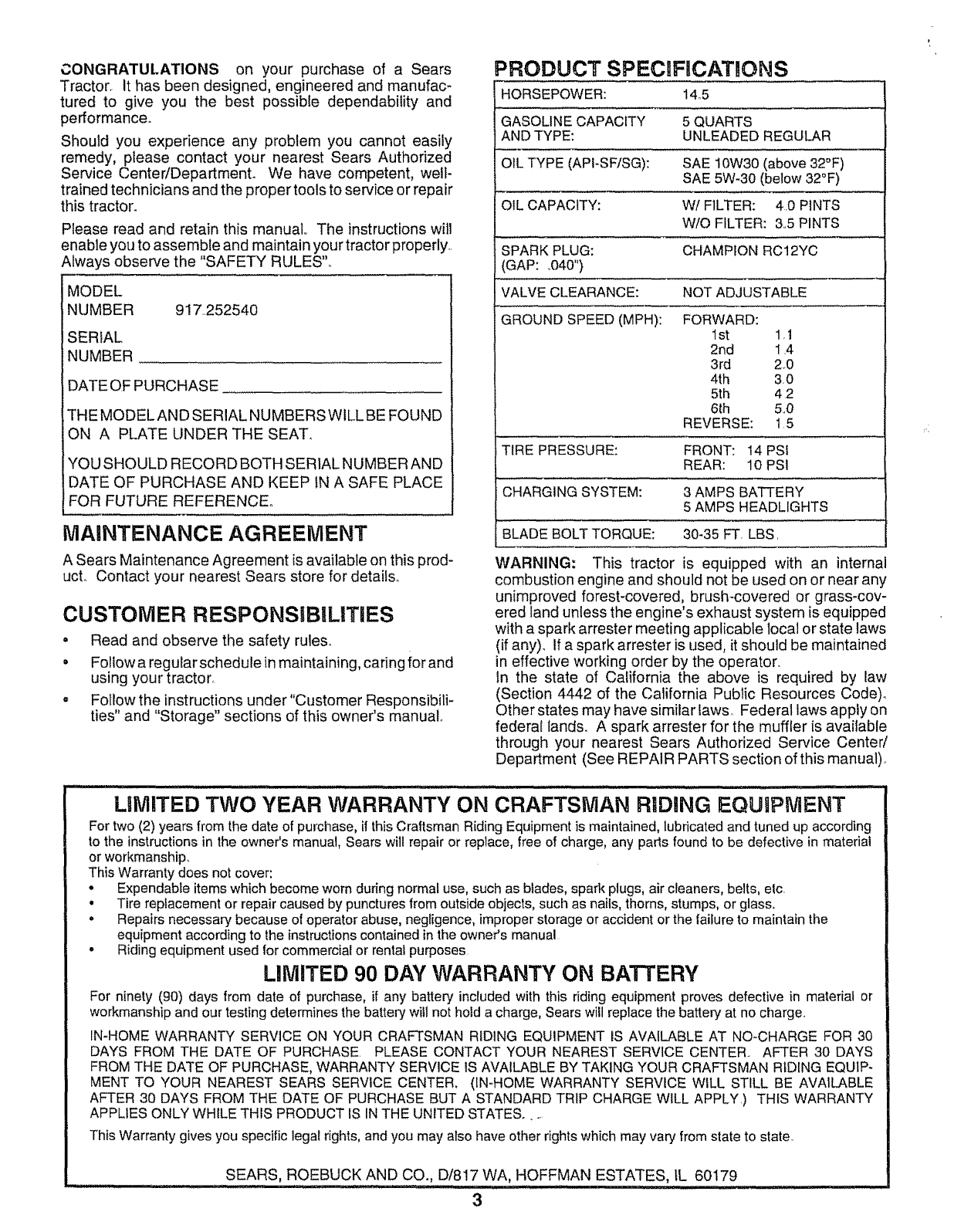
PRODUCT SPECRFICATIONS
HORSEPOWER: 14.5
GASOLINE CAPACITY 5 QUARTS
AND TYPE: UNLEADED REGULAR
OIL TYPE (API-SF/SG): SAE 10W30 (above 32°F)
SAE 5W-30 (below 32°F)
OIL CAPACITY: W/FILTER: 4.0 PINTS
W/O FILTER: 3.5 PINTS
SPARK PLUG: CHAMPION RC12YC
(GAP: .040")
VALVE CLEARANCE: NOT ADJUSTABLE
GROUND SPEED (MPH): FORWARD:
1st 1,1
2nd 1.4
3rd 2_0
4th 3.0
5th 4 2
6th 5..0
REVERSE: 15
TIRE PRESSURE: FRONT: 14 PSI
REAR: 10 PSI
CHARGING SYSTEM: 3 AMPS BATTERY
5 AMPS HEADLIGHTS
BLADE BOLT TORQUE: 30_35 FT, LBS.
WARNING: This tractor is equipped with an internal
combustion engine and should not be used on or near any
unimproved forest-covered, brush-covered or grass-cov-
ered land unless the engine's exhaust system is equipped
with a spark arrester meeting applicable local or state laws
(if any). If a spark arrester is used, it should be maintained
in effective working order by the operator..
In the state of California the above is required by law
(Section 4442 of the California Public Resources Code)_
Other states may have similar laws. Federal laws apply on
federal lands. A spark arrester for the muffler is available
through your nearest Sears Authorized Service Center/
Department (See REPAIR PARTS section of this manual).
.......... iH iH.-...:_... illl¸ ,
LiMiTED TWO YEAR WARRANTY ON CRAFTSMAN RIDING EQUIPMENT
For two (2) years from the date of purchase, if this Craftsman Riding Equipment is maintained, lubricated and tuned up according
to the instructions in the owner's manual, Sears will repair or replace, free of charge, any pads found to be defective in material
or workmanship,
This Warranty does not cover:
•Expendable items which become worn during normal use, such as blades, spark plugs, air cleaners, belts, elc
• Tire replacement or repair caused by punctures from outside objects, such as nails, thorns, stumps, or glass.
• Repairs necessary because of operator abuse, negligence, improper storage or accident or the failure to maintain the
equipment according to the instructions contained in the owner's manual
•Riding equipment used for commercial or rental purposes
LIMITED 90 DAY WARRANTY ON BATTERY
For ninety (90) days from date of purchase, if any batter,] included with this riding equipment proves defective in material or
workmanship and our testing determines the battery will not hold a charge, Sears will replace the battery at no charge.
IN-HOME WARRANTY SERVICE ON YOUR CRAFTSMAN RIDING EQUIPMENT IS AVAILABLE AT NO-CHARGE FOR 30
DAYS FROM THE DATE OF PURCHASE. PLEASE CONTACT YOUR NEAREST SERVICE CENTER.. AFTER 30 DAYS
FROM THE DATE OF PURCHASE, WARRANTY SERVICE IS AVAILABLE BY TAKING YOUR CRAFTSMAN RIDING EQUIP-
MENT TO YOUR NEAREST SEARS SERVICE CENTER_ (IN-HOME WARRANTY SERVICE WILL STILL BE AVAILABLE
AFTER 30 DAYS FROM THE DATE OF PURCHASE BUT A STANDARD TRIP CHARGE WILL APPLY.) THiS WARRANTY
APPLIES ONLY WHILE THIS PRODUCT IS IN THE UNITED STATES ......
This Warranty gives you specific legal rights, and you may also have other rights which may vary from state to state.
HOFFMAN ESTATES, IL 60179SEARS, ROEBUCK AND CO., D/817 WA,, ,
i1, ,. i ,i.i 'II'H ' I I'WlIII'II, ,I 'III ''llw,l:lll,
3
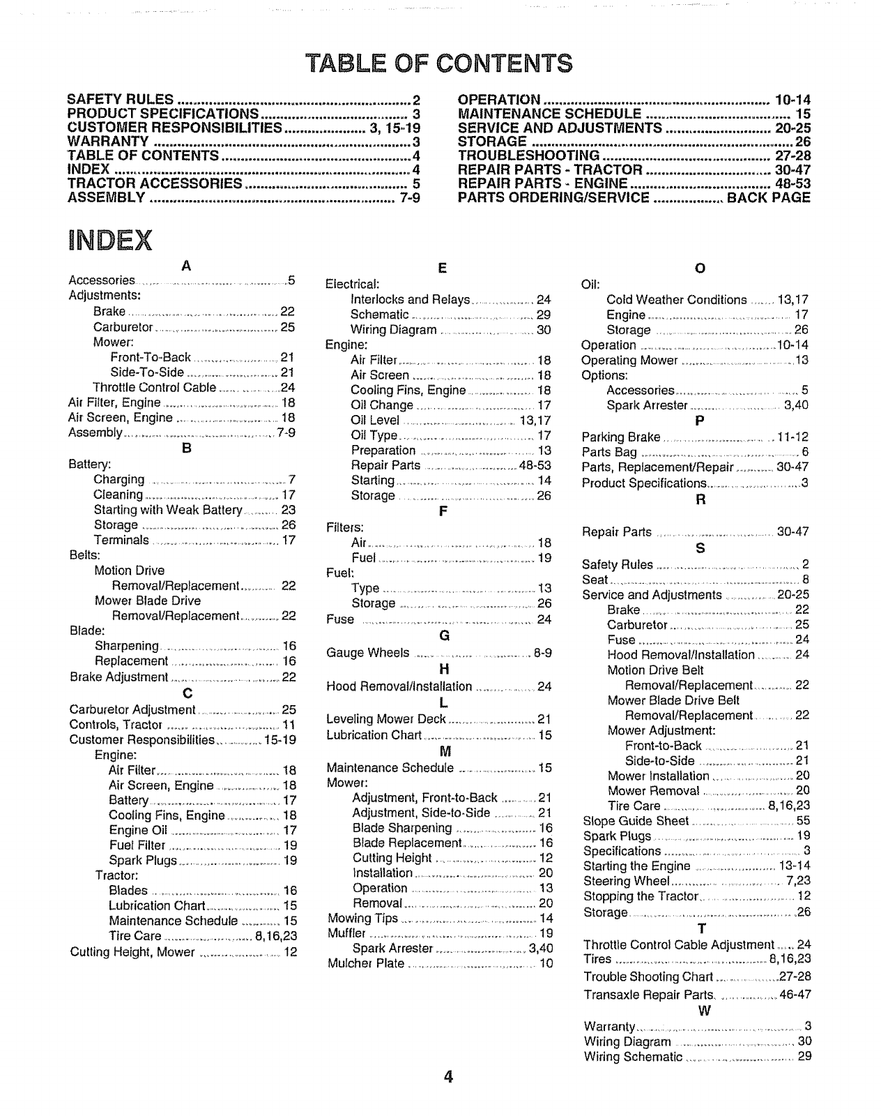
TABLE OF CONTENTS
SAFETY RULES ............................................................ 2
PRODUCT SPECIFICATIONS ...................................... 3
CUSTOMER RESPONSIBILITIES ..................... 3, 15-19
WARRANTY .................................................................. 3
TABLE OF CONTENTS ................................................. 4
INDEX ............................................................................ 4
TRACTOR ACCESSORIES .......................................... 5
ASSEMBLY ............................................................... 7-9
OPERATION .......................................................... 10-14
MAINTENANCE SCHEDULE ..................................... 15
SERVICE AND ADJUSTMENTS ........................... 20-25
STORAG E................................................................... 26
TROUBLESHOOTING ........................................... 27-28
REPAIR PARTS - TRACTOR ................................ 30-47
REPAIR PARTS - ENGINE .................................... 48-53
PARTS ORDERING/SERVICE .................. BACK PAGE
INDEX
A
Accessories ...............................................................5
Adjustments:
Brake ..............................................................22
Carburetor ....................................................25
Mower:
Front-To-Back ..............................21
Side-To-Side ......................................2!
Throttle Control Cable ........................24
Air Filter, Engine ..............................................18
Air Screen, Engine ..........................................18
Assembly .......................................................7-9
B
Battery:
Charging ......................................................7
Cleaning .....................................................17
Starting with Weak Batten,/ ............23
Storage ..................................................26
Terminals ............................................17
Belts:
Motion Drive
Removal/Replacement ...............22
Mower Blade Drive
Removal/Replacement ...............22
Blade:
Sharpening ............................................t6
Replacement .......................................16
Brake Adjustment ........................................22
C
Carburetor Adjustment .................................25
Controls, Tractor, .......................................11
Customer Responsibilities ..................15-19
Engine:
Air Filter ..........................................18
Air Screen, Engine .........................18
Battery ..............................................17
Cooling Fins, Engine ....................18
Engine Oil..............................................17
Fuel Filter,..........................................19
Spark Plugs ......................................19
Tractor:
Blades .................................................16
Lubrication Chad ..............................15
Maintenance Schedule ................15
Tire Care ...................................8,16,23
Cutting Height, Mower .................................12
E
Electrical:
Interlocks and Relays .........................24
Schematic ........................................29
Wiring Diagram .....................................30
Engine:
Air Filter ........................................................18
Air Screen ............................................18
Cooling Fins, Engine ...........................18
Oil Change .............................................17
Oil Level ..........................................13,17
Oit Type ................................................17
Preparation .............................................13
Repair Parts ........................................48-53
Stading ................................................14
Storage ................................................26
F
Fitters:
Air.........................................................18
Fuel ...............................................................19
Fuel:
Type ...............................................................t3
Storage .....................................................26
Fuse ..............................................................24
G
Gauge Wheels ........................................8-9
H
Hood Removalttnstallation ....................24
L
Leveling Mower Deck ..................................21
Lubrication Chad .............................................15
M
Maintenance Schedule ...............................15
Mower:
Adjustment, Front4o-Back ..............21
Adjustment, Side-to-Side ...............2t
Blade Sharpening ..................................16
Blade Replacement ............................16
Cutting Height .....................................12
Installation ..............................................20
Operation ................................................13
Removal .................................................20
Mowing Tips ....................................................14
Muffler ..........................................................i9
Spark Arrestor ..............................3,40
Mulcher Plate .............................................10
4
0
Oil:
Cold Weather Conditions ....... 13,17
Engine ...........................................................17
Storage ............................................................26
Operation .................................................10-14
Operating Mower ..............................................13
Options:
Accessories .................................................5
Spark Arrestor, ............................. 3,40
P
Parking Brake .............................................11-12
Parts Bag ..............................................................6
Parts, Replacement/Repair ..............30-47
Product Specifications .................................3
R
Repair Pads ..........................................30-47
S
Safety Rules ...............................................2
Seat ..................................................................................8
Service and Adjustments .....................20-25
Brake ..........................................................22
Carburetor ...............................................25
Fuse ................................................................24
Hood Removal/Installation ...............24
Motion Ddve Belt
Removal/Replacement ...................22
Mower Blade Drive Belt
Remova!/Replacement ..............22
Mower Adjustment:
Front-to-Back ................................21
Side-to-Side ....................................21
Mower Installation ..............................20
Mower Removal .......................................20
Tire Care ........................................8,16,23
Slope Guide Sheet ....................................55
Spark Plugs ..........................................................19
Specifications ......................................................3
Starling the Engine ...............................13-14
Steering Wheel .....................................7,23
Stopping the Tractor ...................................t2
Storage ..............................................................26
T
Throttle Control Cable Adjustment .......24
Tires .........................................................8,16,23
Trouble Shooting Chad .......................27-28
Transaxle Repair Pads .....................46-47
W
Warranty .............:..................................................3
Wiring Diagram ............................................30
Wiring Schematic .......................................29
ACCESSORIES A ATTACH ENTS
........ i i ...... i i l i, ,l i,,
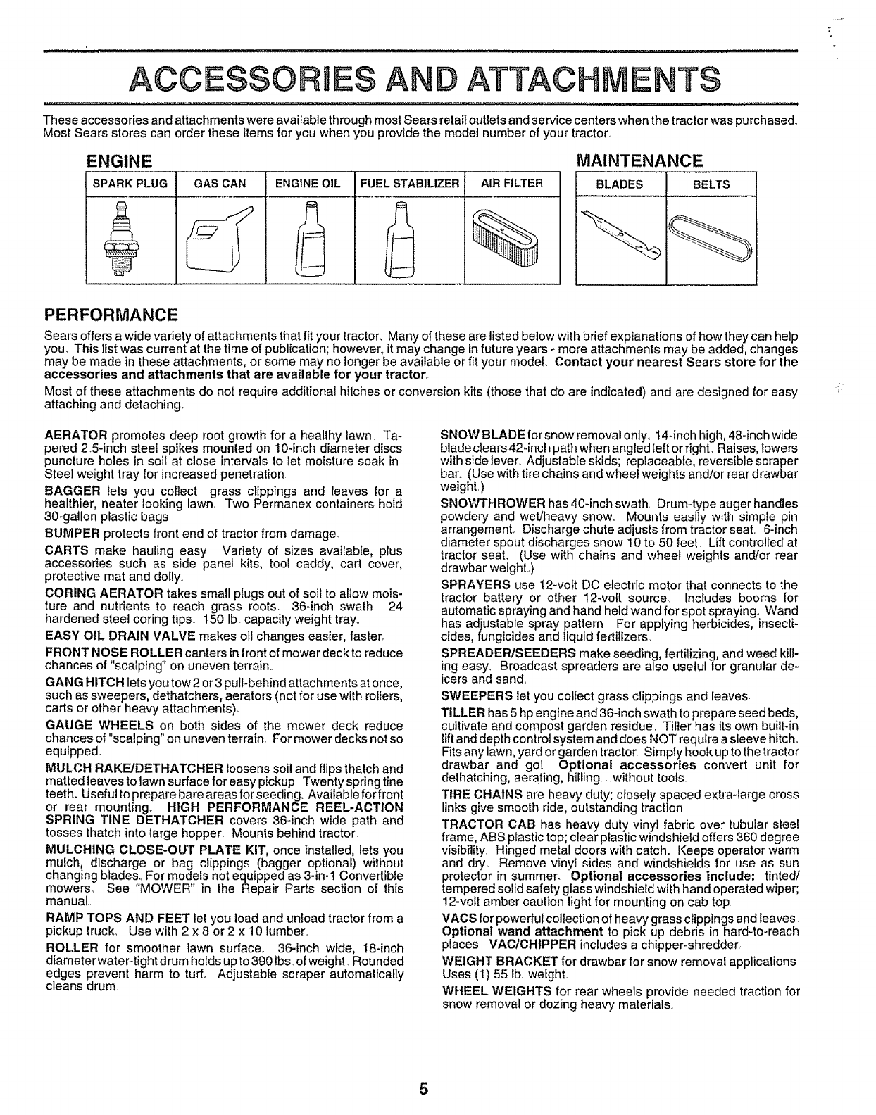
These accessories and attachments were available through most Sears retail outlets and service centers when the tractor was purchased_
Most Sears stores can order these items for you when you provide the model number of your tractor,
ENGINE
SPARK PLUG GAS CAN ENGtNE OIL FUEL STABILIZER AIR FILTER
MAINTENANCE
BLADES BELTS
PERFORMANCE
Sears offers a wide variety of attachments that fit your tractor_ Many of these are listed below with brief explanations of how they can help
you. This list was current at the time of publication; however, it may change in future years _ more attachments may be added, changes
may be made in these attachments, or some may no longer be available or fit your modet. Contact your nearest Sears store for the
accessories and attachments that are available for your tractor.
Most of these attachments do not require additional hitches or conversion kits (those that do are indicated) and are designed for easy
attaching and detaching°
AERATOR promotes deep root growth for a healthy lawn. Ta-
pered 25-inch steel spikes mounted on 10-inch diameter discs
puncture holes in soi_ at close intervals to let moisture soak in.
Steel weight tray for increased penetration
BAGGER lets you collect grass clippings and leaves for a
healthier, neater looking lawn. Two Permanex containers hold
30-gallon plastic bags.
BUMPER protects front end of tractor from damage
CARTS make hauling easy Variety of sizes available, plus
accessories such as side panel kits, tool caddy, cart cover,
protective mat and dolly.
CORING AERATOR takes small plugs out of soil to allow mois-
ture and nutrients to reach grass roots, 36-inch swath 24
hardened steel coring tips 150 lb. capacity weight tray.
EASY OIL DRAIN VALVE makes oil changes easier, faster,
FRONT NOSE ROLLER canters in front of mower deck to reduce
chances of "scalping" on uneven terrain..
GANG HITCH lets you tow 2 or 3 pull-behind attachments at once,
such as sweepers, dethatchers, aerators (not for use with rollers,
carts or other heavy attachments),
GAUGE WHEELS on both sides of the mower deck reduce
chances of "scalping" on uneven terrain, For mower decks not so
equipped.
MULCH RAKE/DETHATCHER loosens soil and flips thatch and
matted leaves to lawn surface for easy pickup. Twenty spring tine
teeth. Useful topreparebareareasforseeding. Availableforfront
or rear mounting. HIGH PERFORMANCE REEL-ACTION
SPRING TINE DETHATCHER covers 36-inch wide path and
tosses thatch into large hopper. Mounts behind tractor.
MULCHING CLOSE-OUT PLATE KIT, once installed, lets you
mulch, discharge or bag clippings (bagger optional) without
changing blades.. For models not equipped as 3-in-1 Convertible
mowers° See "MOWER" in the Repair Parts section of this
manual,
RAMP TOPS AND FEET let you load and unload tractor from a
pickup truck_ Use with 2 x 8 or 2 x 10 lumber..
ROLLER for smoother lawn surface. 36-inch wide, 18*inch
diameterwater-tight drum holds upto 390 lbs.of weight. Rounded
edges prevent harm to turf,. Adjustable scraper automatically
cleans drum
SNOW BLADE for snow removal only. 14-inch high, 48-inch wide
blade clears42-inch path when angled felt or right. Raises, lowers
with side lever Adjustable skids; replaceable, reversible scraper
bar.. (Use with tire chains and wheel weights and/or rear drawbar
weight.)
SNOWTHROWER has 40-inch swath. Drum-type auger handles
powdery and wet/heavy snow., Mounts easily with simple pin
arrangement° Discharge chute adjusts from tractor seat.. 6-inch
diameter spout discharges snow 10 to 50 feet Lift controlled at
tractor seat. (Use with chains and wheel weights and!or rear
drawbar weight..)
SPRAYERS use 12-voft DC electric motor that connects to the
tractor battery or other 12-volt source. Includes booms for
automatic spraying and hand held wand for spot spraying.. Wand
has adjustable spray pattern For applying herbicides, insecti-
cides, fungicides and liquid fertilizers,
SPREADER/SEEDERS make seeding, fertilizing, and weed kill-
ing easy. Broadcast spreaders are also useful for granular de-
icers and sand.
SWEEPERS let you collect grass clippings and leaves,
TILLER has 5 hp engine and 36-inch swath to prepare seed beds,
cultivate and compost garden residue. Tiller has its own built-in
tift and depth control system and does NOT require a sleeve hitch.
Fits any lawn, yard or garden tractor Simply hook up to the tractor
drawbar and go! Optional accessories convert unit for
dethatching, aerating, hilling.., _without tools.
TIRE CHAINS are heavy duty; closely spaced extra-large cross
links give smooth ride, outstanding traction
TRACTOR CAB has heavy duty vinyl fabric over tubular steel
frame, ABS plastic top; clear plastic windshield offers 360 degree
visibility. Hinged metal doors with catch. Keeps operator warm
and dry, Remove vinyl sides and windshierds for use as sun
protector in summer. Optional accessories include: tinted/
tempered solid safety glass windshield with hand operated wiper;
12-volt amber caution light for mounting on cab top
VACS for powerful collection of heavy grass clippings and leaves.
Optional wand attachment to pick up debris in hard-to-reach
places. VAC/CHIPPER includes a chipper-shredder.
WEIGHT BRACKET for drawbar for snow removal applications
Uses (1) 55 lb. weight.
WHEEL WEIGHTS for rear wheels provide needed traction for
snow removal or dozing heavy materials
5

CONTENTS
,,inn,H ..........
OF HARDWARE PACK
i
Parts Bag contents shown full size
O (2) Sheet
Metal
Screws
#10-16 x 1/42
(1) Large Flat Washer
(-
(!) Shoulder Bolt 5t16-18 (1) Hex Bolt 1/2-13 x 1
(1) Lock Washer 1/2
(!) Washer" 17/32 x 1-3116 x 12 Gauge
(2) Screws #10 x 5/8 (2) Lock Washers #10
O(2) Weld Nuts #10 i
ashers 3/16 x 3/4 x 16 Gauge _"
(2) Hex Bolts 114-20 x 314
(2) Hex Nuts 1/4-20
[2) Washers 9/32 x 5/8 x 16 Gauge
(2) Lock Washers !/4
Parts packed separately in carton
Steering
Wheel
Manual
Video
Cassette
Steering
Boot
Il t
Parts Bag
....... IIIIIIIII_IIIIIIUIII_U 11 jLjjj
Parts bag contents not shown full size
n i, ii , ii ...................................
(2) Shoulder
Bolts
Steering Wheel
Adapter
_ok
Assemblys
(2) Washers 3/8
x 7/8 x 14 Gauge
Gauge _ (2) Center-
lock Nuts
(_ Steedng
Bushing
(2) Keys
Slope Sheet
i,, ill ,.......................
Steering
Wheel
Insert
U LJ
6
LY
iiill Ill. I/I/ / IIllllll III,
Your new tractor has been assembled at the factory with exception of those parts left unassembled for shipping purposes.
To ensure safe and proper operation of your tractor all parts and hardware you assemble must be tightened securely. Use
the correct tools as necessary to insure proper tightness°
TOOLS REQUIRED FOR ASSEMBLY
A socket wrench set will make assembly easier.. Standard
wrench sizes are listed_
(1) 5/16" wrench
(2) 7/16" wrenches
(1) 1/2" wrench
(1) 9/16" wrench
(1) 3/4" Socket w/drive rachet
Phillips Screwdriver
Tire pressure gauge
Utility knife
When right or left hand is mentioned in this manual, it
means when you are in the operating position (seated
behind the steering wheel).
TO REMOVE TRACTOR FROM CARTON
UNPACKCARTON
• Remove all accessible loose parts and parts cartons
from carton (See page 6).
. Cut, from top to bottom, along lines on all four corners
of carton, and lay panels flat..
°Check for any additional loose parts or cartons and
remove,
BEFORE ROLLING TRACTOR OFF SKaD
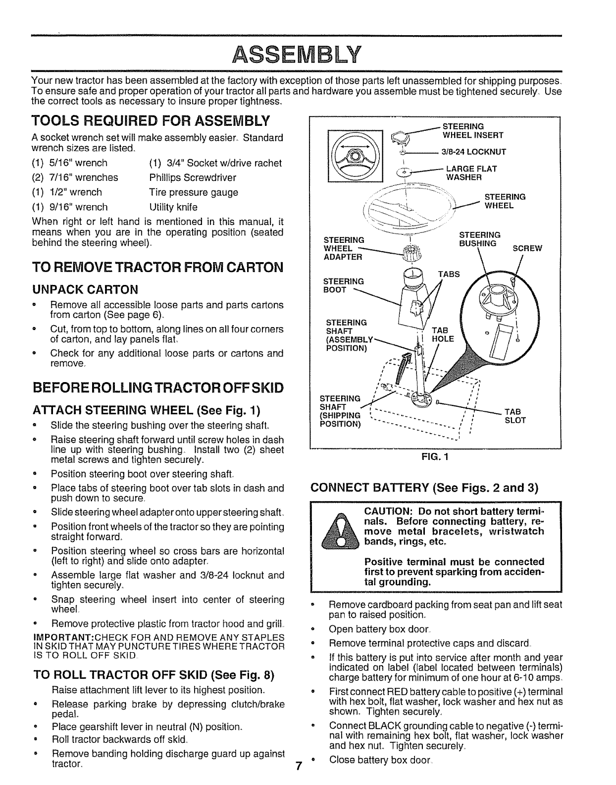
ATTACH STEERING WHEEL (See Fig, 1)
o Slide the steering bushing over the steering shaft°
° Raise steering shaft forward until screw holes in dash
line up with steering bushing, Install two (2) sheet
metal screws and tighten securely°
• Position steering boot over steering shaft
.Place tabs of steering boot over tab slots in dash and
push down to secure.
° Slide steering wheel adapter onto upper stee ring shaft.
-Position front wheels of the tractor so they are pointing
straight forward°
o Position steering wheel so cross bars are horizontal
(left to right) and slide onto adapter_
= Assemble large flat washer and 3/8-24 iocknut and
tighten securely.
°Snap steering wheel insert into center of steering
wheel.
= Remove protective plastic from tractor hood and grill..
IMPORTANT:CHECK FOR AND REMOVE ANY STAPLES
IN SKiD THAT MAY PUNCTURE TIRES WHERE TRACTOR
tS TO ROLL OFF SKiD
TO ROLL TRACTOR OFF SKID (See Fig. 8)
Raise attachment lift lever to its highest position°
° Release parking brake by depressing clutch/brake
pedal
o Place gearshift lever in neutral (N) position.
° Roll tractor backwards off skid,,
• Remove banding holding discharge guard up against
tractor,
STEERING
_WHEEL INSERT
.... 3t8-24 LOCKNUT
_ LARGE FLAT
WASHER
STEERING
STEERING
)_ WHEEL
STEERING
IBUSHING SCREW
TABS
STEERING _ A
,oo
STEERING _ //
SHAFT _TAB
HOLE
POSITION)
STEERING
SHAFT
(SHIPPING
POSITION)
FIG. 1
7
CONNECT BATTERY (See Figs. 2and 3)
CAUTION: Do not short battery termio
_nals. Before connecting battery, re-
move metal bracelets, wristwatch
bands, rings, etco
Positive terminal must be connected
first to prevent sparking from acciden-
tal grounding.
• Remove cardboard packing from seat pan and lift seat
pan to raised position,.
° Open battery box door.
o Remove terminal protective caps and discard.
o If this battery is put into service after month and year
indicated on label (label located between terminals)
charge battery for minimum of one hour at 6-10 amps.
°First connect RED battery cable to positive (+) terminal
with hex bolt, flat washer, lock washer and hex nut as
shown° Tighten securely..
° Connect BLACK grounding cable to negative (-) termi-
nal with remaining hex bolt, fiat washer, lock washer
and hex nut° Tighten securely.
° Close battery box door
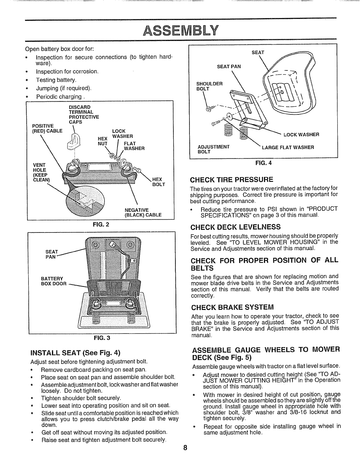
Openbatteryboxdoorfor:
o
o
o
e
ASSEMBLY
Inspection for secure connections (to tighten hard-
ware),,
Inspection for corrosion_
Testing battery,
Jumping (if required)_
Periodic charging ,.
POSITIVE
(RED) CABLE
DISCARD
TERMINAL
PROTECTIVE
CAPS
_, HEX
NUT
LOCK
WASHER
FLAT
WASHER
VENT
HOLE
(KEEP
CLEAN) BOLT
NEGATIVE
(BLACK) CABLE
FIG. 2
SEA"['
PAN
BATTERY
BOXDOOR
FIG, 3
SEAT PAN
SEAT
,\
LOCK WASHER
ADJUSTMENT LARGE FLAT WASHER
BOLT
FIG. 4
CHECK TIRE PRESSURE
The tires on your tractor were overinflated at the factory for
shipping purposes, Correct tire pressure is important for
best cutting performance,.
o Reduce tire pressure to PS! shown in "PRODUCT
SPECIFICATIONS" on page 3 of this manual
CHECK DECK LEVELNESS
Forbest cutting results, mower housing should be propedy
leveled. See "TO LEVEL MOWER HOUSING" in the
Service and Adjustments section of this manual,
CHECK FOR PROPER POSITION OF ALL
BELTS
See the figures that are shown for replacing motion and
mower blade drive belts in the Service and Adjustments
section of this manual_ Verify that the belts are routed
correctty._
CHECK BRAKE SYSTEM
After you learn how to operate your tractor, check to see
that the brake is properly adjusted1. See "TO ADJUST
BRAKE" in the Service and Adjustments section of this
rnanuat.
INSTALL SEAT (See Fig. 4)
Adjust seat before tightening adjustment bolt.,
• Remove cardboard packing on seat pan..
oPlace seat on seat pan and assemble shoulder bolt,
•Assemble adjustment bolt, lock washer and flat washer
loosely, Do not tighten°
•Tighten shoulder bolt securely,
°Lower seat into operating position and sit on seat°
o Slide seat until a comfortable position is reached which
allows you to press clutch/brake pedal all the way
down°
° Get off seat without moving its adjusted position..
o Raise seat and tighten adjustment bolt securely.
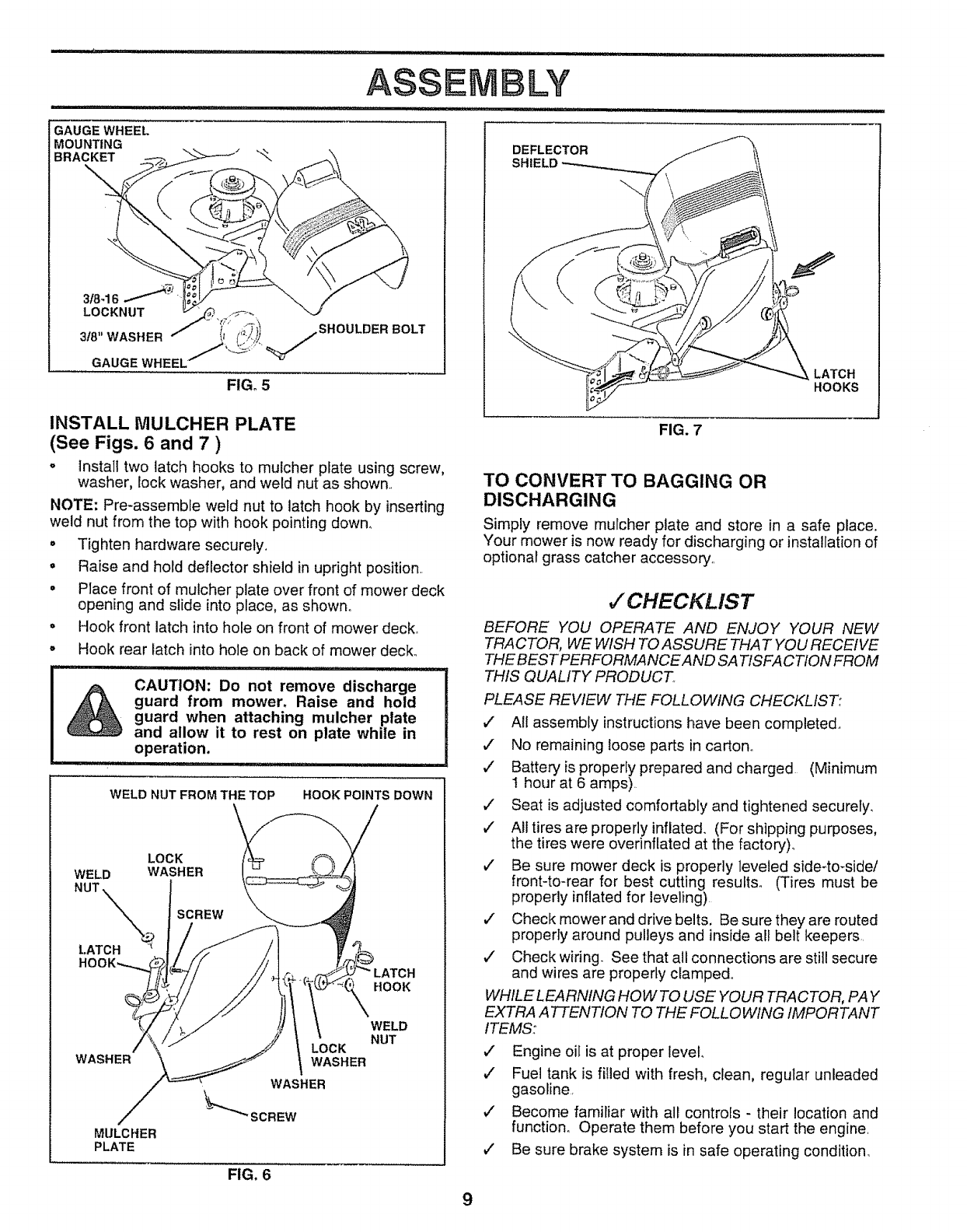
ASSEMBLE GAUGE WHEELS TO MOWER
DECK (See Fig. 5)
Assemble gauge wheels with tractor on a fiat level surface,
o Adjust mower to desired cutting height (See "TO AD-
JUST MOWER CUTTING HEIGHT" in the Operation
section of this manual),,
° With mower in desired height of cut position, gauge
wheels should be assembled so they are slightly off the
ground, Install gauge wheel in appropriate hole with
shoulder bolt, 3/8 washer and 3/8-I6 Iocknut and
tighten securefy,
° Repeat for opposite side installing gauge wheel in
same adjustment hole.
8
ASSE LY
GAUGE WHEEL
MOUNTING
BRACKET
318-16.-_'_
LOCKNUT
318" WASHER
GAUGE WHEEL
_,,/.SHOULDER BOLT
FIG, 5
INSTALL MULCHER PLATE
(See Figs, 6 and 7 )
oinstall two latch hooks to mulcher plate using screw,
washer, lock washer, and weld nut as shown..
NOTE: Pre-assemble weld nut to latch hook by inserting
weld nut from the top with hook pointing down_
• Tighten hardware securely..
. Raise and hold deflector shield in upright position.
° Place front of mulcher plate over front of mower deck
opening and slide into place, as shown_
. Hook front latch into hole on front of mower deck.
° Hook rear latch into hole on back of mower deck°
CAUTION: Do not remove discharge
guard from mower. Raise and hold
guard when attaching mulcher plate
and allow it to rest on plate while in
operation.
WELD NUT FROM THE TOP HOOK POINTS DOWN
LOCK
WELD WASHER
NUT ,.\\\\ SCREW
t.ATCH _
LATCH
HOOK
WASHER
MULCHER
PLATE
LOCK
WASHER
WASHER
_SCREW
FIG. 6
WELD
NUT
DEFLECTOR
SHIELD
FIG. 7
LATCH
HOOKS
TO CONVERT TO BAGGING OR
DISCHARGING
Simply remove mulcher plate and store in a safe place.
Your mower is now ready for discharging or installation of
optional grass catcher accessory.
,/CHECKLIST
BEFORE YOU OPERATE AND ENJOY YOUR NEW
TRACTOR, WE WISH TO ASSURE THAT YOU RECEIVE
THE BEST PERFORMANCE AND SATISFACTION FROM
THIS QUALITY PRODUCT
PLEASE REVIEW THE FOLLOWING CHECKLIST:
,/ Al! assembly instructions have been completed..
v" No remaining loose parts in carton°
v" Batteryis property prepared and charged (Minimum
1 hour at 6 amps).
v" Seat is adjusted comfortably and tightened securely.
,/ All tires are properly inflated. (For shipping purposes,
the tires were overinflated at the factory).
v" Be sure mower deck is properly leveled side-to-sidel
front-to-rear for best cutting results. (Tires must be
properly inflated for leveling)
,/ Check mower and drive belts. Be sure they are routed
properly around pulleys and inside all belt keepers,
,/ Check wiring. See that all connections are still secure
and wires are properly clamped_
WHILELEARNING HOWTO USE YOUR TRACTOR, PAY
EXTRA A 7TENTION TO THE FOLLOWING IMPORTANT
ITEMS:
¢' Engine oil is at proper level..
¢" Fuel tank is filled with fresh, clean, regular unleaded
gasoline.
¢" Become familiar with all controls - their location and
function. Operate them before you start the engine.
,/ Be sure brake system is in safe operating condition.
9
......... ::::::1111i i ii i ii
OPERATmON
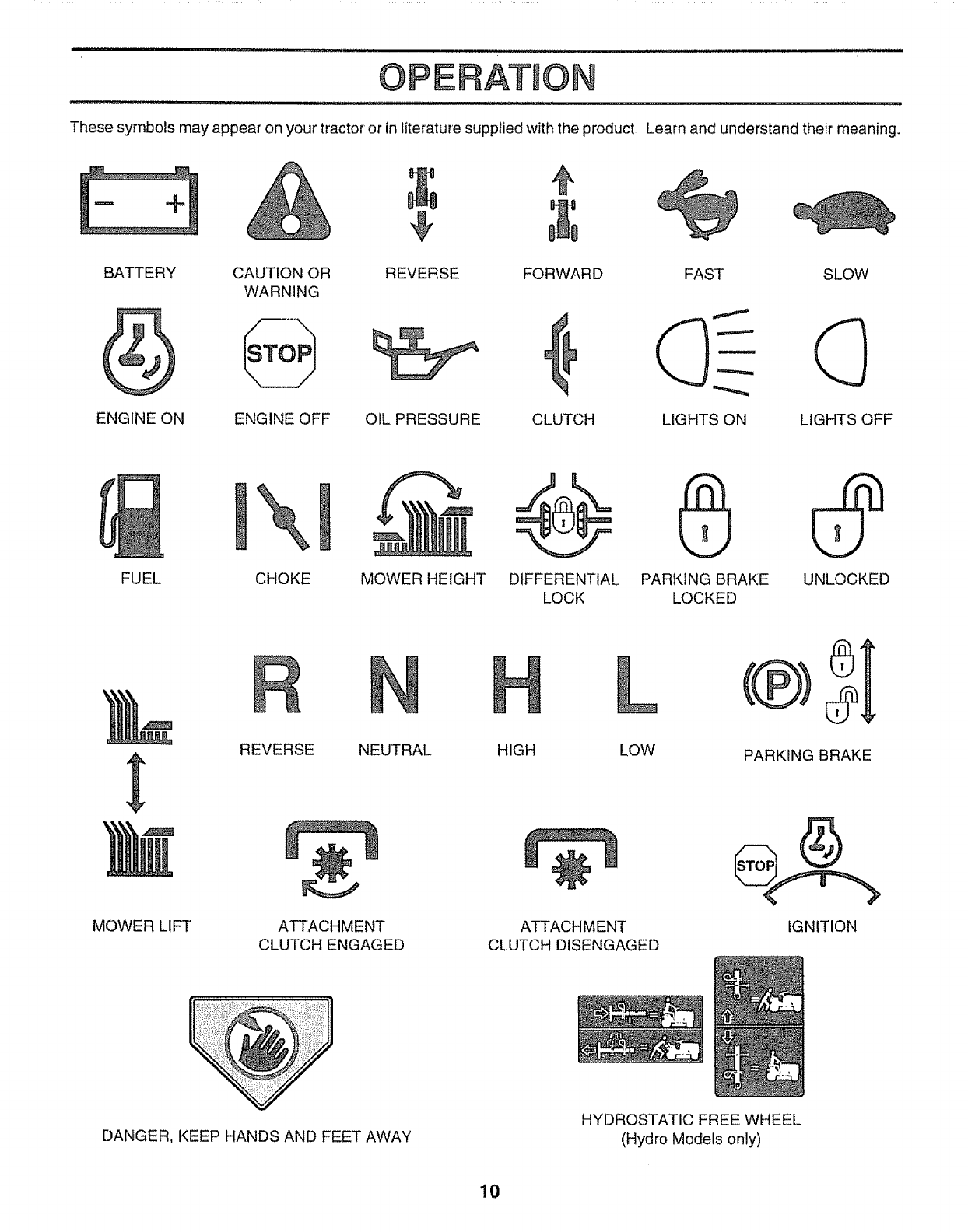
These symbols may appear on your tractor or in literature supplied with the product, Learn and understand their meaning.
BATTERY CAUTION OR SLOW
WARNING
ENGfNE ON ENGINE OFF LIGHTS OFF
REVERSE FORWARD FAST
d)-
OIL PRESSURE CLUTCH LIGHTS ON
FUEL UNLOCKED
X
CHOKE MOWER HEIGHT DIFFERENTIAL PARKING BRAKE
LOCK LOCKED
MOWER LIFT
REVERSE NEUTRAL HIGH LOW
ATTACHMENT
CLUTCH ENGAGED
÷
ATTACHMENT
CLUTCH DISENGAGED
PARKING BRAKE
IGNITION
DANGER, KEEP HANDS AND FEET AWAY
HYDROSTATIC FREE WHEEL
(Hydro Models only)
10
OPERATION
,..ill ,i ii ,ll ii i i
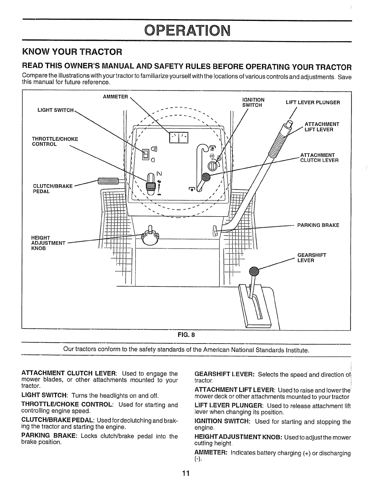
KNOW YOUR TRACTOR
READ THIS OWNER'S MANUAL AND SAFETY RULES BEFORE OPERATING YOUR TRACTOR
Comparethe illustrations withyourtractor to familiarize yourself with the locations of various controls and adjustments, Save
this manual for future reference°
THROTTLE/CHOKE
CONTROL
CLUTCHIBRAKE
PEDAL
HEIGHT
ADJUSTMENT
KNOB
AMMETER
I\1
IGNITION LIFT LEVER PLUNGER
SWITCH /
ATTACHMENT
ATTACHMENT
LEVER
PARKING BRAKE
GEARSHIFT
LEVER
FIG. 8
Our tractors conform to the safety standards of the American National Standards Institute_
ATTACHMENT CLUTCFt LEVER: Used to engage the
mower blades, or other attachments mounted to your
tractor_
LIGHT SWITCH: Turns the headlights on and off.
THROTTLE/CHOKE CONTROL: Used for starting and
controlling engine speed°
CLUTCHtBRAKE PEDAL: Used for declutching and brak-
ing the tractor and starting the engine°
PARKING BRAKE: Locks clutch/brake pedal into the
brake position°
I
GEARSHIFT L.EVER: Selects the speed and direction o_
tractor, i
ATTACHMENT LIFT LEVER: Used to raise and lower the
mower deck or other attachments mounted to your tractor,
LIFT LEVER PLUNGER: Used to release attachment lift
lever when changing its position,,
IGNITION SWITCH: Used for starting and stopping the
engine.
HEIGHTADJUSTMENT KNOB; Used to adjust the mower
cutting height.
AMMETER: Indicates battery charging (+) or discharging
11
OPERAT OIN
The operation of any tractor can result in foreign objects thrown into the eyes, which can
result in severe eye damage. Always wear safety glasses or eye shields while operating your
tractor or performing any adjustments or repairs. We recommend awide vision safety mask
over the spectacles or standard safety glasses.
HOW TO USE YOUR TRACTOR
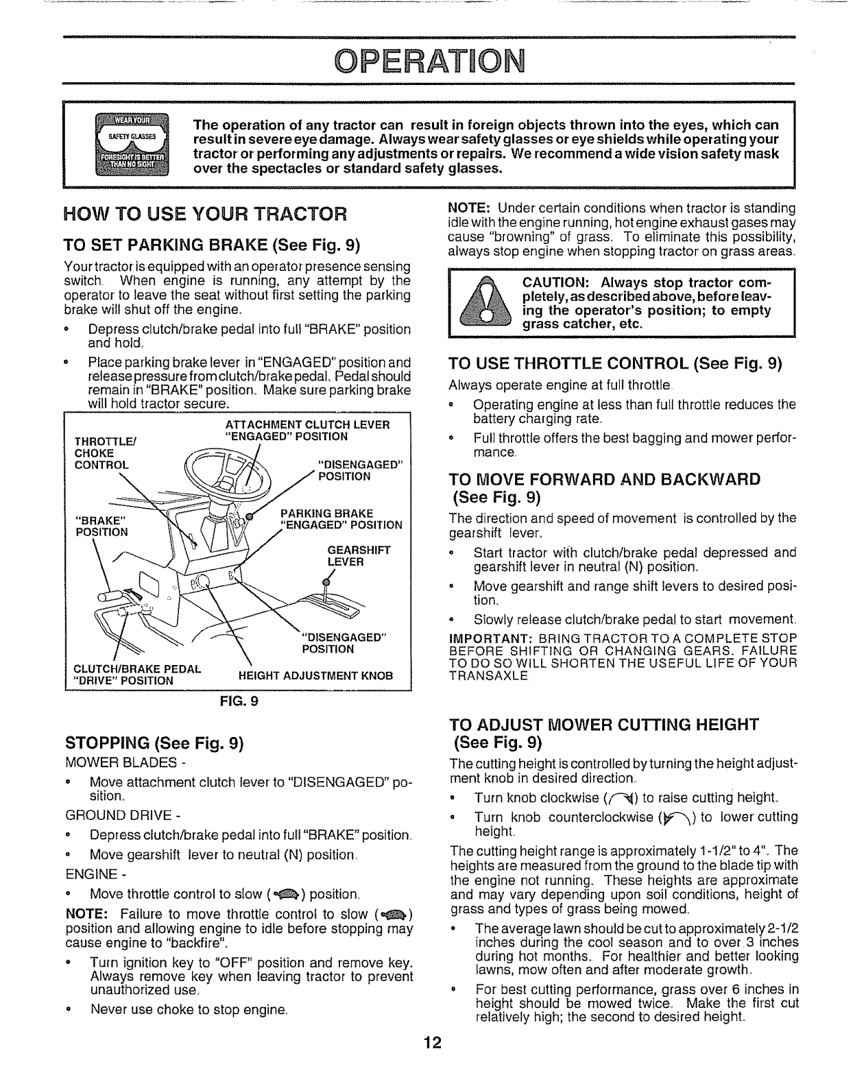
TO SET PARKING BRAKE (See Fig. 9)
Your tractoris equipped with an operator presence sensing
switch. When engine is running, any attempt by the
operator to leave the seat without first setting the parking
brake will shut off the engine.
°Depress clutch/brake pedal into full "BRAKE" position
and hotd_
Place parking brake lever in "ENGAGED" position and
release pressure from clutch/brake pedal.. Pedal should
remain in "BRAKE" position.. Make sure parking brake
will hold tractor secure.
THROTTLE/
CHOKE
CONTROL
ATTACHMENT CLUTCH LEVER
"ENGAGED" POSITION
"DISENGAGED"
POSITION
"BRAKE"
POSITION
PARKING BRAKE
!'ENGAGED" POSITION
GEARSHIFT
LEVER
CLUTCHIBRAKE PEDAL
"DRIVE" POSITION
"DISENGAGED"
POSITION
HEIGHT ADJUSTMENT KNOB
FIG. 9
STOPPING (See Fig. 9)
MOWER BLADES -
° Move attachment clutch lever to "DISENGAGED" po-
sitiono
GROUND DRIVE -
o Depress clutch/brake pedal into full "BRAKE" position.
= Move gearshift lever to neutral (N) position.
ENGINE -
•Move throttle control to slow (_,) position.
NOTE: Failure to move throttle control to slow (°_,)
position and allowing engine to idle before stopping may
cause engine to "backfire".
° Turn ignition key to "OFF" position and remove key.
Always remove key when leaving tractor to prevent
unauthorized use.
= Never use choke to stop engine.
NOTE: Under certain conditions when tractor is standing
idle with the engine running, hot engine exhaust gases may
cause "browning" of grass. To eliminate this possibility,
always stop engine when stopping tractor on grass area&
CAUTION: Always stop tractor com-
pletely, as described above, before leav-
ing the operator's position; to empty
grass catcher, etc.
TO USE T!tROTTLE CONTROL (See Fig. 9)
Always operate engine at full throttle
o Operating engine at less than full throttle reduces the
battery charging rate..
= Full throttle offers the best bagging and mower perfor-
mance.
TO MOVE FORWARD AND BACKWARD
(See Fig, 9)
The direction and speed of movement is controlled by the
gearshift lever.
o Start tractor wit'h clutch/brake pedal depressed and
gearshift lever in neutral (N) position.,
. Move gearshift and range shift levers to desired posi-
tion.
o Slowly release clutch/brake pedal to start movemenL
IMPORTANT; BRING TRACTOR TO A COMPLETE STOP
BEFORE SHIFTING OR CHANGING GEARS. FAILURE
TO DO SO WILL SHORTEN THE USEFUL LIFE OF YOUR
TRANSAXLE
TO ADJUST MOWER CUTTING HEIGHT
(See Fig. 9)
The cutting height is controlled by turning the height adjust-
ment knob in desired direction..
o Turn knob clockwise (f'-_) to raise cutting height.
° Turn knob counterclockwise (_p-_) to lower'cutting
height,
The cutting height range is approximately 1-1/2" to 4L The
heights are measured from the ground to the blade tip with
the engine not running., These heights are approximate
and may vary depending upon soil conditions, height of
grass and types of grass being mowed
• The average lawn should be cut to approximately 2-1/2
inches during the cool season and to over 3 inches
during hot months. For healthier and better looking
lawns, mew often and after moderate growth,
=For best cutting performance, .grass over6 inches in
height should be mewed twice., Make the first cut
relatively high; the second to desired heighL
12
OPEF AT ON
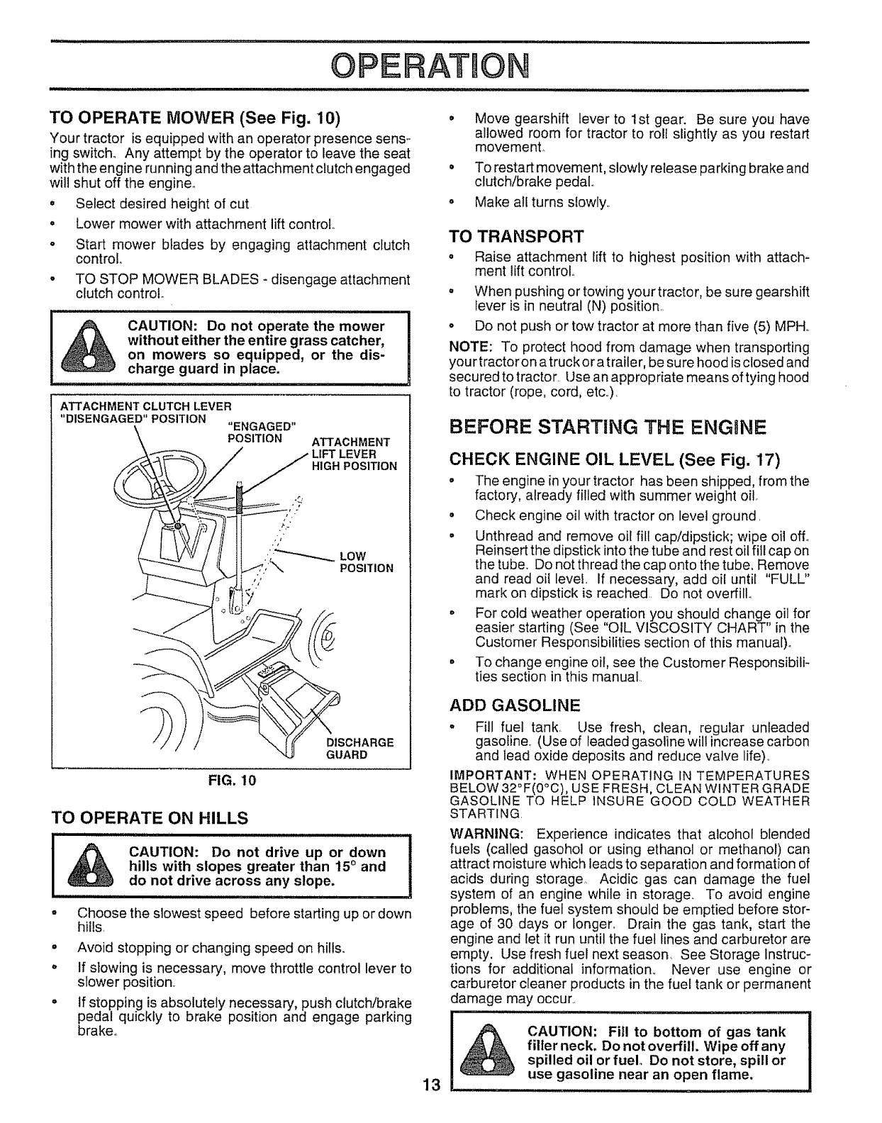
TO OPERATE MOWER (See Fig. 10)
Your tractor is equipped with an operator presence sens-
ing switch.. Any attempt by the operator to leave the seat
with the engine runnJngand the attachment clutch engaged
will shut off the engine°
• Select desired height of cut
Lower mower with attachment lift control
o
oStart mower blades by engaging attachment clutch
control
TO STOP MOWER BLADES - disengage attachment
clutch control°
,illll ,IL,i,l,ll, ,ll,,iJll,,i ii i, i , i1,1, i
CAUTION: Do not operate the mower
without either the entire grass catcher,
on mowers so equipped, or the dis-
charge guard in place.
ATTACHMENT CLUTCH LEVER
"DISENGAGED" POSITION "ENGAGED"
POSITION ATTACHMENT
HIGH POSITION
FIG, 10
DISCHARGE
GUARD
TO OPERATE ON HILLS
CAUTION: Do not drive up or down
hills with slopes greater than 15°and
do not drive across any slope.
Choose the slowest speed before starting up or down
hills,
• Avoid stopping or changing speed on hills.
o If slowing is necessary, move throttle control lever to
slower position.
° If stopping is absolutely necessary, push clutch/brake
pedal quickly to brake position and engage parking
brake°
Move gearshift lever to 1st gear. Be sure you have
allowed room for tractor to roll slightly as you restart
movemenL
To restart movement, slowly release parking brake and
clutch/brake pedal.
Make all turns slowly,.
TO TRANSPORT
o Raise attachment lift to highest position with attach-
ment lift control..
= When pushing or towing your tractor, be sure gearshift
lever is in neutral (N) position,.
- Do not push or tow tractor at more than five (5) MPH,,
NOTE: To protect hood from damage when transporting
you rtractor on atruck or a trailer, be sure hood is closed and
secured to tractor, Use an appropriate means of tying hood
to tractor (rope, cord, etc,),
BEFORE STARTING THE ENGINE
CHECK ENGINE OIL LEVEL (See Fig, 17)
•The engine in your tractor has been shipped, from the
factory, already filled with summer weight oil.
° Check engine oil with tractor on level ground
• Unthread and remove oil fill cap/dipstick; wipe oil off.,
Reinsert the dipstick into the tube and rest oil fill cap on
the tube.. Do not thread the cap onto the tube, Remove
and read oi{ level. If necessary, add oil until "FULL"
mark on dipstick is reached. Do not overfill.,
• For cold weather operation you should change oil for
easier starting (See "OIL VISCOSITY CHART" in the
Customer Responsibilities section of this manual)°
• To change engine oil, see the Customer Responsibili-
ties section in this manual
13
ADD GASOLINE
•Fill fuel tank, Use fresh, clean, regular unleaded
gasoline. (Use of leaded gasoline will increase carbon
and lead oxide deposits and reduce valve life)_
IMPORTANT: WHEN OPERATING IN TEMPERATURES
BELOW 32°F(0_C), USE FRESH, CLEAN WINTER GRADE
GASOLINE TO HELP INSURE GOOD COLD WEATHER
STARTING
WARNING: Experience indicates that alcohol blended
fuels (called gasohol or using ethanol or methanol) can
attract moisture which leads to separation and formation of
acids during storage. Acidic gas can damage the fuel
system of an engine while in storage_ To avoid engine
problems, the fuel system should be emptied before stor-
age of 30 days or longer. Drain the gas tank, start the
engine and let it run until the fuel lines and carburetor are
empty, Use fresh fuel next season_ See Storage Instruc-
tions for additional information,, Never use engine or
carburetor cleaner products in the fuel tank or permanent
damage may occur.,
CAUTION: Fill to bottom of gas tank
filler neck, Do not overfill, Wipe off any
spilled oil or fuel Do not store, spill or
use gasoline near an open flame,
,,11 ill 11 =
TO START ENGINE (See Fig. 9)
When starting engine for' the first time or if engine has run
out of fuel, it will take extra cranking time to move fuel from
the tank to the engine..
•Depress clutch/brake pedal and set parking brake._
o Place gearshift lever in neutral (N) position..
• Move attachment clutch to "DISENGAGED" position.
o Move throttle control lever to choke ( t",l ) position for
cold engine start_ For warm engine start, move throttle
control to fast (,_) position_
o Insert key into ignitionand turn keyctockwise to"START"
position and release key as soon as engine starts. Do
not run starter continuously for more than fifteen
seconds per minute.. If engine does not start after
several attempts, move throttle control to fast (,_)
position, wait a few minutes and try again..
° When engine starts, move throttle control to desired
position,
° Allow engine to warm up for a few minutes before
engaging drive or attachments,,
NOTE: if at a high altitude (above 3000 feet) or in cold
temperatures (below 32°F), the carburetor fuel mixture
may need to be adjusted for best engine performance. See
"TO ADJUST CARBURETOR" in the Service and Adjust-
ments section of this manual..
MOWING TiPS
Tire chains cannot be used when the mower housing
is attached to tractor'.
° Mower-should be properly leveled for best mowing
performance. See '%0 LEVEL MOWER HOUSING" in
the Service and Adjustments section of this manual..
° The left hand side of mower should be used for trim-
ming.
• Drive so that clippings are discharged onto the area
that has been cut. Have the cut area to the right of the
machine° This will result in a more even distribution of
clippings and more uniform cutting.
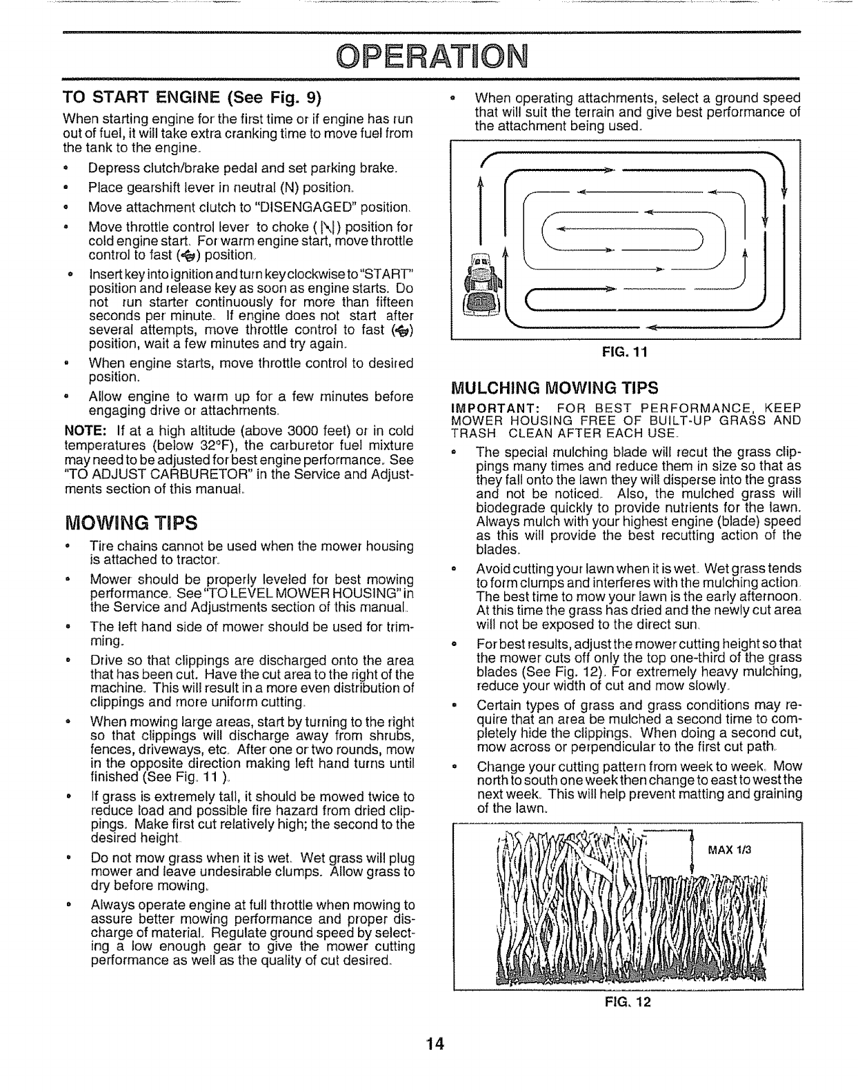
° When mowing large areas, start by turning to the right
so that clippings will discharge away from shrubs,
fences, driveways, etc_ After one or two rounds, mow
in the opposite direction making left hand turns until
finished (See Fig° 11 )o
• tf grass is extremely tall, it should be mowed twice to
reduce load and possible fire hazard from dried clip-
pings. Make first cut relatively high; the second to the
desired height.
• Do not mow grass when it is wet. Wet grass will plug
mower and leave undesirable clumps° Allow grass to
dry before mowing.
• Always operate engine at full throttle when mowing to
assure better mowing performance and proper dis-
charge of materiat_ Regulate ground speed by select-
ing a tow enough gear to give the mower cutting
performance as weil as the quality of cut desired.
A ON
° When operating attachments, select a ground speed
that will suit the terrain and give best performance of
the attachment being used.
FIG. 11
MULCHING MOWING TIPS
IMPORTANT: FOR BEST PERFORMANCE, KEEP
MOWER HOUSING FREE OF BUILT-UP GRASS AND
TRASH CLEAN AFTER EACH USE..
The special mulching blade will recur the grass clip-
pings many times and reduce them in size so that as
they fall onto the lawn they wil! disperse into the grass
and not be noticed.. Also, the mulched grass will
biodegrade quickly to provide nutrients for the lawn.
Always mulch with your highest engine (blade) speed
as this will provide the best recutting action of the
blades..
= Avoid cutting your lawn when it is wet. Wet grass tends
to form clumps and interferes with the mulching action
The best time to mow your lawn is the early afternoon..
At this time the grass has dried and the newly cut area
will not be exposed to the direct sun.
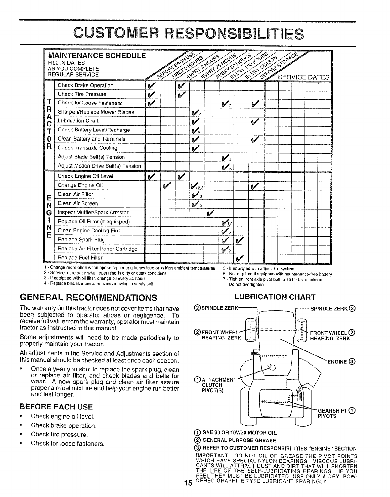
° For best results, adjust the mower cutting height so that
the mower cuts off only the top one-third of the grass
blades (See Fig. 12). For extremely heavy mulching,
reduce your width of cut and mow slowly..
° Certain types of grass and grass conditions may re-
quire that an area be mulched a second time to com-
pletely hide the clippings. When doing a second cut,
mow across or perpendicular to the first cut path.
° Change your cutting pattern from week to week. Mow
north to south one week then change to east to west the
next week° This will help prevent matting and graining
of the lawn.
FIG, 12
MAX 1t3
14
CUSTO RESPON ILITIES
u, NNl"::" INNNIN I
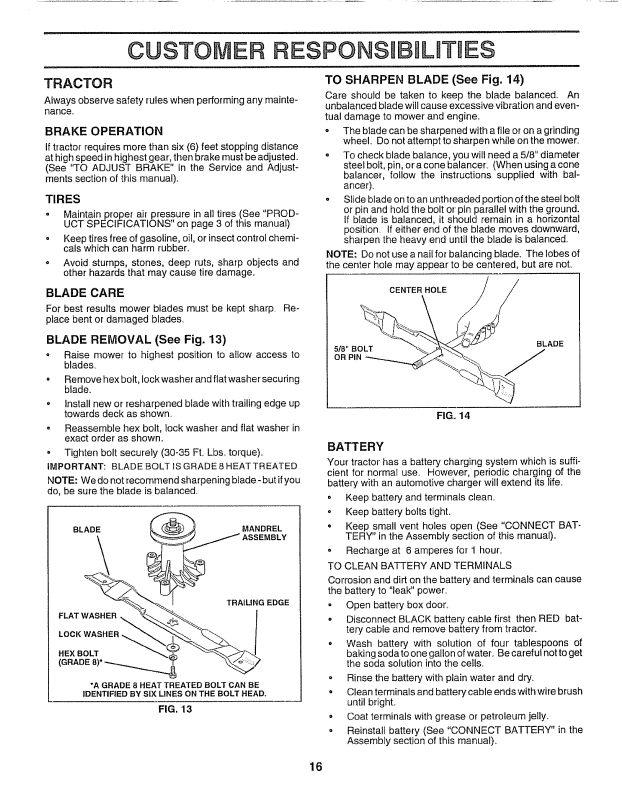
=,,,.,,c=sc.=0u.=
FILL IN DATES
REGULARSERVICE....., /__ft'_E RVI CE DATE S i
Check BrakeOperation 6/ 6/
CheckTire Pressure 6/446##'
TCheck for LooseFasteners 6/ 6/#476/
R sharpeniReplace MowerBlades ..................... 6f4 ...........
LubricationChart .............. _ (If * '
C......
T CheckBatteryLeve!iRiecharge .....i'ii"............... _ ..... "
0Clean BatteryandTerminals $#*' 6/
aCheckTransaxteCooling 6#4
Adjust Blade Belt(s) Tension _'s
Ad!us!MotionDriveB_e[!(s)Tension ...... _5. '
Check EngineOil Level 6/ 6/ ......
_ChangeEngineOil ., 6/ .................._t,2,3
E ,,,.CleanAir F!!ter.......... 6/'2
NCleanAir Screen 6/2
iG InspectMuffledSparkArrester 6/
Repiacielllio" Filter (1, equipped)' ' 1 r .............. , : ' _.2
CleanEnginecooling Fins .................. _#'2 "
E..... .............
Replace Spark Plug ........................ 644 =6/ I ............
ReplaceAir Filler PaperCartridge $/'2
ReplaceFuelFilter 6/
I
1 * Change mere ollen when operating under a heavy load or in htgh ambient lempe_atu[es
2 - Service mere olten when opefaltng in dirty or dusly cendtlions
3-I! equipped with elf Iitler, change oil every 50 hours
4 - Replace blades more ellen when mowing In sandy soi!
I - I! equipped wilh adiustable system
0 - Not required if equipped wilh mainlenance4ree baiter.i
7 - Tighlen Iron[ axle pivot bolt to 35 f{ -Ibs maximum
Do net ovedighlen
GENERAL RECOMMEN DATIONS
The warranty on this tractor does not cover items that have
been subjected to operator abuse or negligence., To
receive full value from the warranty, operator must maintain
tractor as instructed in this manual,
Some adjustments will need to be made periodically to
properly maintain your tractor°
All adjustments in the Service and Adjustments section of
this manual should be checked at least once each season.
• Once a year you should replace the spark plug, clean
or replace air filter, and check blades and belts for
wear,, A new spark plug and clean air filter assure
proper air-fuel mixture and help your engine run better
and last longer°
BEFORE EACH USE
° Check engine oil level,,
• Check brake operation°
° Check tire pressure,,
• Check for loose fasteners,,
LUBRICATION CHART
(_SPINDLE ZERK_ .[_- SPINDLE ZERK (_)
@FRONT WHEEL=====================================FRONT WHEEL (_)
BEARING ZERK _ '1| f_ BEARING ZERK
1
®
CLUTCH
PIVOT(S)
GEARSHIFT (_)
PIVOTS
(_) SAE 30 OR 10W30 MOTOR OIL
(_) GENERAL PURPOSE GREASE
(_) REFER TO CUSTOMER RESPONSIBILITIES "ENGINE" SECTION
IMPORTANT: DO NOT OIL OR GREASE THE PIVOT POINTS
WHICH HAVE SPECIAL NYLON BEARINGS VISCOUS LUBRI.
CANTS WILL ATTRACT DUST AND DiRT THAT WILL SHORTEN
THE LIFE OF THE SELF-LUBRICATING BEARINGS. IF YOU
FEEL THEY MUST BE LUBRICATED, USE ONLY A DRY, POW-
15 DERED GRAPHITE TYPE LUBRICANT SPARINGLY
CUSTO E
i,, i,/,i i i iJ ,llll ill ill i,, ,, i,i J ul ,,ulllu,,i,,H,,
TRACTOR
Always observe safety rules when performing any mainte-
nance.
BRAKE OPERATION
If tractor requires more than six (6) feet stopping distance
at high speed in highest gear, then brake must be adjusted..
(See 'q'o ADJUST BRAKE" in the Service and Adjust-
ments section of this rnanua0.
TIRES
o Maintain proper air pressure in all tires (See "PROD-
UCT SPECIFICATIONS" on page 3 of this manual)
• Keep tires free of gasoline, oil, or insect control chemi-
cals which can harm rubber'.,
o Avoid stumps, stones, deep ruts, sharp objects and
other hazards that may cause tire damage.
BLADE CARE
For best results mower' blades must be kept sharp Re-
place bent or damaged blades,.
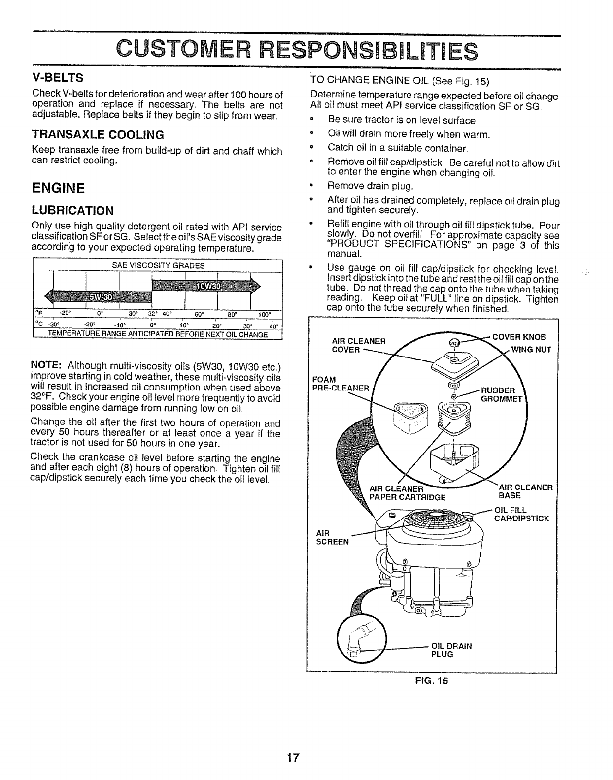
BLADE REMOVAL (See Fig. 13)
• Raise mower to highest position to allow access to
blades..
• Remove hex bolt, lock washer and flat washer secu ring
blade.,
o install new or resharpened blade with trailing edge up
towards deck as shown.
o Reassemble hex bolt, lock washer and flat washer in
exact order as shown.
° Tighten bolt securely (30-35 FL Lbs_ torque),,
IMPORTANT: BLADE BOLT IS GRADE 8 HEAT TREATED
NOTE: We do not recommend sharpening blade - but ifyou
do, be sure the blade is balanced.
BLADE MANDREL
ASSEMBLY
TRAILING EDGE
FLAT WASHER _, !
HEX BOLT
(GRADE
*A GRADE 8 HEAT TREATED BOLT CAN BE
IDENTIFIED BY SIX LINES ON THE BOLT HEAD.
FIG. 13
ESPONS JLITtES
TO SHARPEN BLADE (See Fig. 14)
Care should be taken to keep the blade balanced° An
unbalanced blade will cause excessive vibration and even-
tual damage to mower and engine.,
o The blade can be sharpened with a file or on a grinding
wheel. Do not attempt to sharpen while on the mower.
° To check blade balance, you will need a 5/8" diameter
steel bolt, pin, or a cone balancer_ (When using a cone
balancer, follow the instructions supplied with bal-
ancer).
°Slide blade on to an unthreaded portion of the steel bolt
or pin and hold the bolt or pin parallel with the ground.
If blade is balanced, it should remain in a horizontal
position. If either end of the blade moves downward,
sharpen the heavy end until the blade is balanced.,
NOTE: Do not use a nail for balancing blade. The lobes of
the center hole may appear to be centered, but are not°
CENTER HOLE
5/8" BOLT
OR PIN
BLADE
FIG. 14
BATTERY
Your tractor' has a battery charging system which is suffi-
cient for normal use., However, periodic charging of the
battery with an automotive charger will extend its life.
° Keep battery and terminals clean.
• Keep battery bolts tight.
o Keep small vent holes open (See "CONNECT BAT-
TERY" in the Assembly section of this manual),
° Recharge at 6 amperes for 1 hour.
TO CLEAN BATTERY AND TERMINALS
Corrosion and dirt on the battery and terminals can cause
the battery to "leak" power,.
, Open battery box door,
°Disconnect BLACK battery cable first then RED bat-
tery cable and remove battery from tractor.
°Wash battery with solution of four' tablespoons of
baking soda to one gallon of water,. Be careful not to get
the soda solution into the cells,.
°Rinse the battery with plain water and dry.
o Clean terminals and battery cable ends with wire brush
until brighL
• Coat terminals with grease or petroleum jelly,.
° Reinstall battery (See "CONNECT BATTERY" in the
Assembly section of this manual)_
16
V-BELTS
Check V-belts for deterioration and wear after 100 hours of
operation and replace if necessary_ The belts are not
adjustable° Replace belts if they begin to slip from wear_, o
TRANSAXLE COOLING °
Keep transaxle free from build_up of dirt and chaff which °
can restrict cooling. °
ENGINE
LUBRICATION
Only use high quality detergent oil rated with API service
classification SF or SG. Select the oil's SAE viscosity grade
according to your expected operating temperature°
SAE VISCOSITY GRADES
L
-20" 04 30" 32 =' 40" 60 _ 60 ° !00 °
°C 0"
.... .30°-20° -10°,,,,!0_ ....................20= 30' 4 o
TE,MPERATURE RANGE ANTICIPATED BEFORE NEXT OIL CHANGE
NOTE: Although multi-viscosity oils (5W30, 10VV30 etc.,)
improve starting in cold weather, these multi-viscosity oils
wilt result in increased oil consumption when used above
32°F. Check your engine oil level more frequently to avoid
possible engine damage from running low on oil,
Change the oil after the first two hours of operation and
every 50 hours thereafter or at least once a year if the
tractor is not used for 50 hours in one year.
Check the crankcase oil level before starting the engine
and after each eight (8) hours of operation_ Tighten oil fill
cap/dipstick securely each time you check the oil level
TO CHANGE ENGINE OIL (See Fig_ 15)
Determine temperature range expected before oil change
All oil must meet API service classification SF or SG,
°
o
Be sure tractor is on level surface
Oil will drain more freely when warm,
Catch oi! in a suitable container,,
Remove oil fill cap/dipstick, Be careful not to allow dirt
to enter the engine when changing oil,,
Remove drain plugo
After oil has drained completely, replace oil drain plug
and tighten securely.
Refill engine with oil through oil fill dipstick tube. Pour
slowly. Do not overfill. For approximate capacity see
"PRODUCT SPECIFICATIONS" on page 3 of this
manual.
Use gauge on oil fill cap/dipstick for checking level.
Insert dipstick into the tube and rest the oil fill cap on the
tube. Do not thread the cap onto the tube when taking
reading., Keep oil at "FULL" line on dipstick. Tighten
cap onto the tube securely when finished.
AIR CLEANER KNOB
COVER NUT
FOAM
PRE-CLEANER
AIR
SCREEN
PAPER CARTRIDGE
CLEANER
BASE
:ILL
CAP/DIPSTICK
DRAIN
PLUG
FIG. 15
17
ESPO ILITIES
AIR FILTER (See Fig. 15)
Your engine wilt not run properly using a dirty air filter,.
Clean the foam pre-cleaner after every 25 hours of opera-
tion or every season. Service paper' cartridge every 100
hours of operation or every season, whichever occurs first.
Service air' cleaner more often under dusty conditions..
•Remove knob and cover_
• Remove wing nut and air cleaner from base.
TO SERVICE PRE-CLEANER
°Slide foam pre-cleaner off cartridge.
•Wash it in liquid detergent and water_
•Squeeze it dry in a clean cloth.
°Saturate it in engine oil. Wrap it in clean, absorbent
cloth and squeeze to remove excess oil
TO SERVICE CARTRIDGE
•Gently tap the flat side of the paper cartridge to dis-
lodge dirt. Do not wash the paper cartridge or use
pressurized air, as this will damage the cartridge.
Replace a dirty, bent, or damaged cartridge.
o Reinstall the pre-cteaner (cleaned and oiled) over the
paper cartridge..
oReassemble air' cleaner, wing nut, cover and tighten
knob securely.
CLEAN AIR INTAKE/COOLING AREAS
To insure proper cooling, make sure the grass screen,
cooling fins, and other external surfaces of the engine are
kept clean at all times.
Every 100 hours of operation (more often under extremely
dusty, dirty conditions), remove the blower housing and
other cooling shrouds. Clean the cooling fins and external
surfaces as necessary. Make sure the cooling shrouds are
reinstalled,.
NOTE: Operating the engine with a blocked grass screen,
dirty or plugged cooling fins, and/or cooling shrouds re-
moved will cause engine damage due to overheating.
MUFFLER
Inspect and replace corroded muffler and spark arrester (if
equipped) as it could create a fire hazard and/or damage.
SPARK PLUGS
Replace spark plugs at the beginning of each mowing
season or' after every 100 hours of operation, whichever
occurs first. Spark plug type and gap setting are shown in
"PRODUCT SPECIFICATIONS" on page 3 of this manual.
CLEAN AIR SCREEN (See Fig. 15)
Air screen must be kept free of dirt and chaff to prevent
engine damage from overheating. Clean with a wire brush
or compressed air to remove dirt and stubborn dried gum
fibers..
18
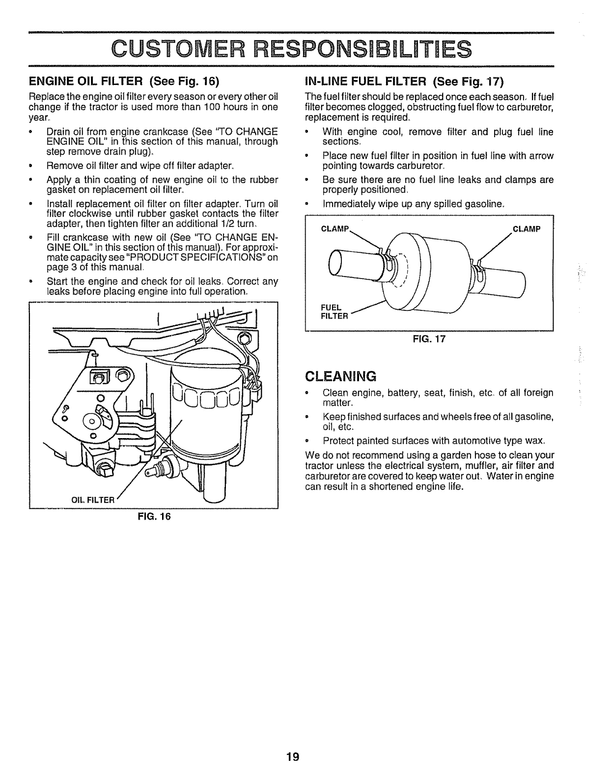
ENGINE OIL FILTER (See Fig. 16)
Replace the engine oil filter every season or every other oil
change if the tractor is used more than 100 hours in one
year°
oDrain oil from engine crankcase (See "TO CHANGE
ENGINE OIL" in this section of this manual, through
step remove drain plug).
• Remove oil filter and wipe off filter adapter°
° Apply a thin coating of new engine oil to the rubber
gasket on replacement oil filter°
° Install replacement oil filter on filter adapter° Turn oil
filter clockwise until rubber gasket contacts the filter
adapter, then tighten filter an additional 1/2 turn_
° Fill crankcase with new oil (See "TO CHANGE EN-
GINE OIL" in this section of this manual). For approxi-
mate capacity see "PRODUCT SPECIFICATIONS" on
page 3 of this manual°
• Start the engine and check for oil leaks, Correct any
teaks before placing engine into full operation.
IN-LINE FUEL FILTER (See Fig. 17)
The fuel filter should be replaced once each season. If fuel
filter becomes clogged, obstructing fuel flow to carburetor,
replacement is required°
• With engine cool, remove filter and plug fuel line
sections.
• Place new fuel filter in position in fuel line with arrow
pointing towards carburetor,.
°Be sure there are no fuel line leaks and clamps are
properly positioned.
= Immediately wipe up any spilled gasoline°
CLAMP CLAMP
FUEL
FILTER
FIG. 17
CLEANmNG
oClean engine, battery, seat, finish, etc_ of all foreign
matter°
° Keep finished surfaces and wheels free of all gasoline,
oil, etc.
o Protect painted surfaces with automotive type wax.
We do not recommend using a garden hose to clean your
tractor unless the electrical system, muffler, air filter and
carburetor are covered to keep water out, Water in engine
can result in a shortened engine life.
FIG. 16
i!,:
19
SERVICE AND ADJUSTMENTS
CAUTION:
@
o
o
o
o
BEFORE PERFORMING ANY SERVICE OR ADJUSTMENTS:
Depress clutch/brake pedal fully and set parking brake.
Place gearshift lever in neutral (N) position,
Place attachment clutch in "DISENGAGED" position.
Turn ignition key "OFF" and remove key.
Make sure the blades and all moving parts have completely stopped.
Disconnect spark plug wire from spark plug and place wire where it cannot come in contact with
plug,
TRACTOR
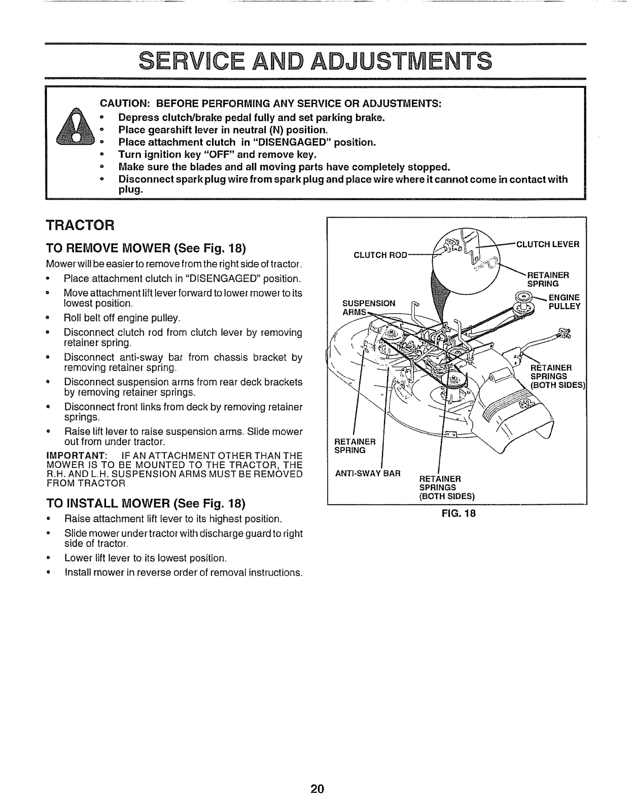
TO REMOVE MOWER (See Fig. 18)
Mower wi!lbe easier to remove from the right side of tractor.
o Place attachment clutch in "DISENGAGED" position.
o Move attachment lift lever forward to lower mower to its
lowest position
° Roll belt off engine pulley
o Disconnect clutch rod from clutch lever by removing
retainer spring
• Disconnect anti-sway bar from chassis bracket by
removing retainer spring_
, Disconnect suspension arms from rear deck brackets
by removing retainer springs,
° Disconnect front links from deck by removing retainer
springs_
° Raise lift lever to raise suspension arms Slide mower
out from under tractor,
IMPORTANT: IF AN ATTACHMENT OTHER THAN THE
MOWER IS TO BE MOUNTED TO THE TRACTOR, THE
R.H. AND L,H, SUSPENSION ARMS MUST BE REMOVED
FROM TRACTOR
TO INSTALL MOWER (See Fig. 18)
° Raise attachment lift lever to its highest position,
° Slide mower under tractorwith discharge guardto right
side of tractor
o Lower iiftlever to its lowest position,
° install mower in reverse order of removal instructions.
RETAINER
SPRING
ANTI-SWAY BAR RETAINER
SPRINGS
(BOTH SIDES)
FIG. 18
LEVER
]ETAINER
SPRING
2O
SERVmCE AN ADJUSTMENTS
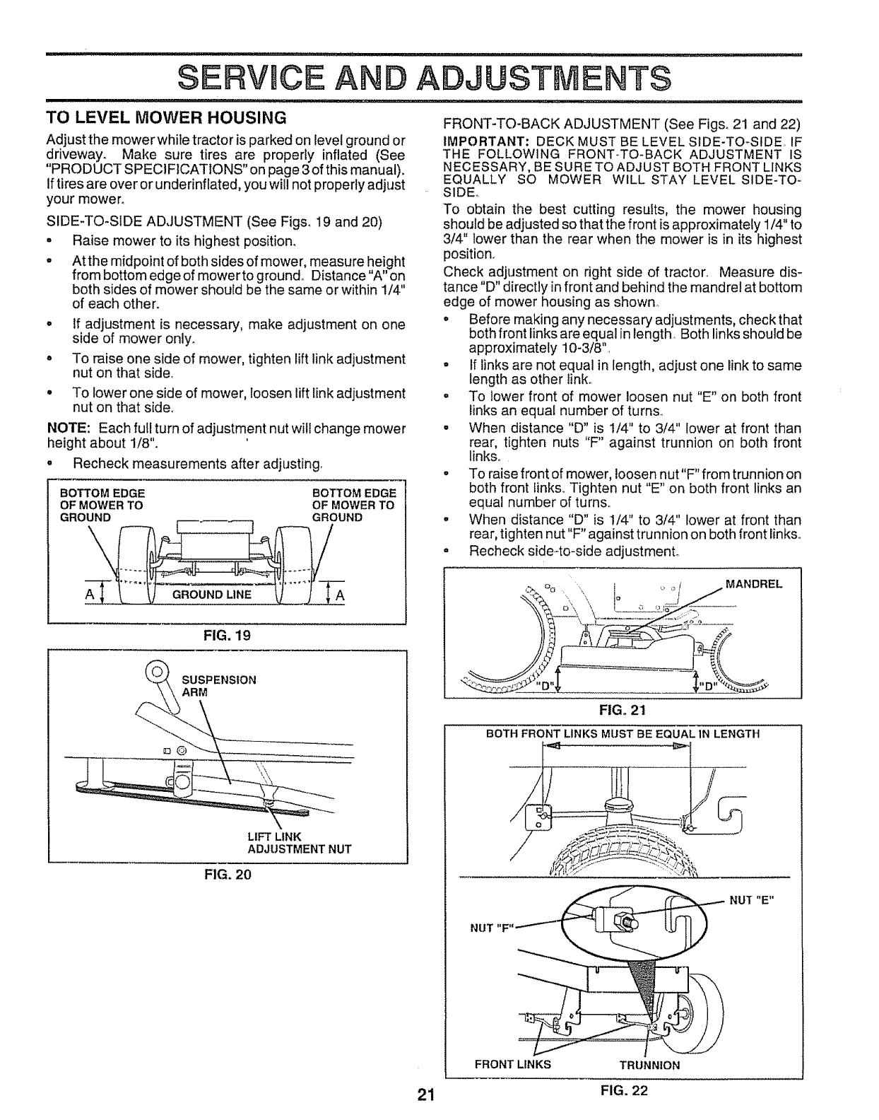
TO LEVEL MOWER HOUSING FRONT-TO-BACK ADJUSTMENT (See Figs. 21 and 22)
IMPORTANT: DECK MUST BE LEVEL SIDE-TO-SIDE,, IF
THE FOLLOWING FRONT-TO-BACK ADJUSTMENT IS
NECESSARY, BE SURE TO ADJUST BOTH FRONT LINKS
EQUALLY SO MOWER WILL STAY LEVEL SIDE-TO-
SIDE.,
To obtain the best cutting results, the mower housing
should be adjusted so that the front is approximately 1/4" to
3/4" lower than the rear when the mower is in its highest
position.
Check adjustment on right side of tractor. Measure dis-
tance "D" directly in front and behind the mandrel at bottom
edge of mower housing as shown,
o• Before making any necessary adjustments, check that
both front links are equal in length, Both links should be
approximately 10-3/8",
°• If links are not equal in length, adjust one link to same
length as other link.
. To lower front of mower loosen nut "E" on both front
links an equal number of turns.
• When distance "D" is 1/4" to 3/4" lower at front than
rear, tighten nuts "F" against trunnion on both front
links.
• To raise front of mower, loosen nut "F" from trunnion on
both front links,, Tighten nut "E" on both front links an
equal number of turn&,
•When distance "D" is 1/4" to 3/4" lower at front than
rear, tighten nut"F" against trunnion on both front links,,
• Recheck side4o-side adjustment°
Adjust the mower while tractor is parked on level ground or
driveway° Make sure tires are properly inflated (See
"PRODUCT SPECIFICATIONS" on page 3 of this manual).
Iftires are over or underinflated, you will not properly adjust
your mower°
SIDE-TO-SIDE ADJUSTMENT (See Figs. 19 and 20)
° Raise mower to its highest position.
° At the midpoint of both sides of mower, measure height
from bottom edge of mower to ground,, Distance "A" on
both sides of mower should be the same or within 1/4"
of each other°
If adjustment is necessary, make adjustment on one
side of mower only,,
To raise one side of mower, tighten lift link adjustment
nut on that side,
° To lower one side of mower, loosen lift link adjustment
nut on that side°
NOTE: Each full turn of adjustment nut will change mower
height about 1/8".
°Recheck measurements after adjusting
BOTTOM EDGE BOTTOM EDGE
OF MOWER TO OF MOWER TO
GROUND GROUND
GROUND LINE A
FIG. 19
SUSPENSION
ARM
LIFT LINK
ADJUSTMENT NUT
FIG. 20
:>, % ",, _ _ ,,_ MANDREL
\\ '-,r'
FIG. 21
BOTH FRONT LINKS MUST BE EQUAL 1N LENGTH
NUI "E"
NUT "F"
FRONT LINKS TRUNNION
21 FIG. 22
SERVHCE AND ADJUSTMENTS
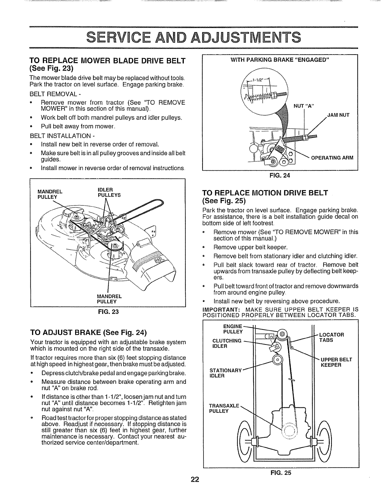
TO REPLACE MOWER BLADE DRIVE BELT
(See Fig. 23)
The mower'blade drive belt may be replaced without tools,.
Park the tractor on level su_ace,_ Engage parking brake._
BELT REMOVAL-
• Remove mower from tractor (See "TO REMOVE
MOWER" in this section of this manual),
• Work belt off both mandrel pulleys and idler pulleys.
= Pull belt away from mower,,
BELT INSTALLATION -
• Install new belt in reverse order of removal.
. Make su re belt is in all pulley grooves and inside a!l belt
guides°
. install mower in reverse order of removal instructions
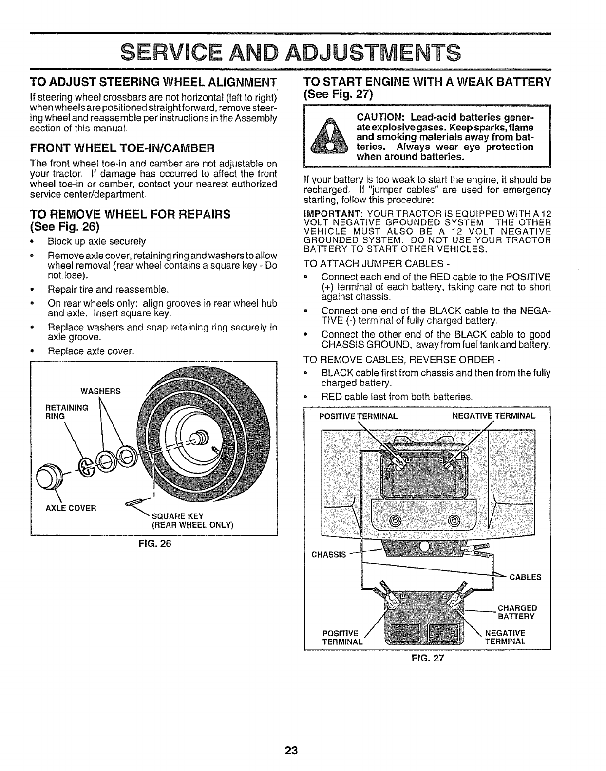
WITH PARKING BRAKE "ENGAGED"
FIG. 24
MANDREL IDLER
PULLEY PULLEYS
MANDREL
PULLEY
FIG. 23
TO ADJUST BRAKE (See Fig. 24)
Your tractor is equipped with an adjustable brake system
which is mounted on the right side of the transaxle_
tf tractor requires more than six (6) feet stopping distance
at high speed in highest gear-, then brake must be adjusted.
° Depress clutch/brake pedal and engage parking brake.
. Measure distance between brake operating arm and
nut "A" on brake rod,,
If distance is other than 1-1/2", loosen jam nut and turn
nut "A" until distance becomes 1-1/2",, Retighten jam
nut against nut "A",
Road test tractor for proper stopping distance as stated
above. Readjust if necessary. If stopping distance is
still greater than six (6) feet in highest gear, further
maintenance is necessary. Contact your nearest au-
thorized service center/department_
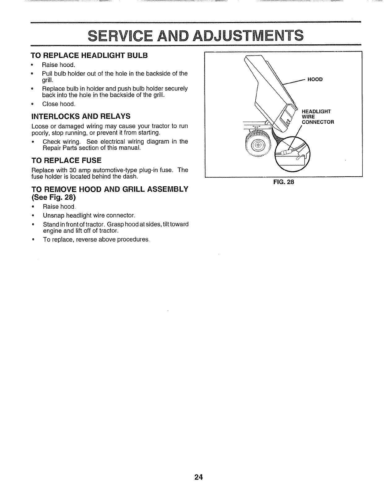
TO REPLACE MOTION DRIVE BELT
(See Fig. 25)
Park the tractor on levei surface,, Engage parking brake,,
For' assistance, there is a belt installation guide decal on
bottom side of left footrest.
o Remove mower (See "TO REMOVE MOWER" in this
section of this manuaL)
° Remove upper belt keeper,.
= Remove belt from stationary idler and clutching idler,
o Pull heft slack toward rear of tractor, Remove belt
upwards from transaxle pulley by deflecting belt keep-
ers,,
o Pull belt toward front of tractor and remove downwards
from around engine pu]ley_
°instatt new belt by reversing above procedure.
IMPORTANT: MAKE SURE UPPER BELT KEEPER IS
POSITIONED PROPERLY BETWEEN LOCATOR TABS.
ENG
PULLEY
CLUTCHING
IDLER
LOCATOR
TABS
UPPER BELT
KEEPER
IDLER
TRANSAXLE
PULLEY
22 FIG. 25
ERVmCEAN ADJUSTMENTS
TO ADJUST STEERING WHEEL ALIGNMENT
If steering wheel crossbars are not horizontal (left to right)
when wheels are positioned straightforward, remove steer-
ing wheel and reassemble per instructions in the Assembly
section of this manual
FRONT WHEEL TOE-IN/CAMBER
The front wheel toe-in and camber are not adjustable on
your tractor, if damage has occurred to affect the front
wheel toe-in or camber, contact your nearest authorized
service center/department,,
TO REMOVE WHEEL FOR REPAIRS
(See Fig. 26)
•Block up axle secure{y,
° Remove axle cover, retaining ring and washers to allow
TO START ENGINE WITH AWEAK BATTERY
See Fig. 27)
_u=_,,, _
CAUTION; Lead-acid batteries gener-
ate explosive gases. Keep sparks, flame
and smoking materials away from bat-
teries. Always wear eye protection
when around batteries.
If your battery is too weak to start the engine, it should be
recharged° If "jumper cables" are used for emergency
starting, follow this procedure:
IMPORTANT: YOUR TRACTOR IS EQUIPPED WITH A 12
VOLT NEGATIVE GROUNDED SYSTEM THE OTHER
VEHICLE MUST ALSO BE A 12 VOLT NEGATIVE
GROUNDED SYSTEM, DO NOT USE YOUR TRACTOR
BATTERY TO START OTHER VEHICLES_
wheel removal (rear wheel contains a square key - Do
not Iose)_
•Repair tire and reassemble°
°On rear wheels only: align grooves in rear wheel hub
and axle. Insert square key.
• Replace washers and snap retaining ring securely in
axle groove.
• Replace axle cover.
WASHERS
RETAINING
RING
AXLE COVER
1
_"SQUARE KEY
(REAR WHEEL ONLY)
FIG. 26
TO ATTACH JUMPER CABLES -
o Connect each end of the RED cable to the POSITIVE
(+) terminal of each battery, taking care not to short
against chassis,
= Connect one end of the BLACK cable to the NEGA-
TIVE (-) terminal of fully charged battery_
° Connect the other end of the BLACK cable to good
CHASSIS GROUND, away from fuel tank and battery
TO REMOVE CABLES, REVERSE ORDER -
= BLACK cable first from chassis and then from the fully
charged battery.
° RED cabte last from both batteries,
POSITIVE TERMINAL NEGATIVE TERMINAL
CHASSIS
CABLES
CHARGED
BATTERY
POSITIVE NEGATIVE
TERMINAL TERMINAL
FIG. 27
23
SERVUCE AND ADJ STMENTS
TO REPLACE HEADLIGHT BULB
, Raise hood.
= Pull bulb holder out of the hole in the backside of the
grill.
= Replace bulb in holder and push bulb holder securely
back into the hole in the backside of the grill
, CIosehood_
INTERLOCKS AND RELAYS
Loose or damaged wiring may cause your tractor' to run
poorly, stop running, or prevent it from starting.
= Check wiring_ See electrical wiring diagram in the
Repair Parts section of this manual.
TO REPLACE FUSE
Replace with 30 amp automotive-type pfug-in fuse. The
fuse holder' is located behind the dash.
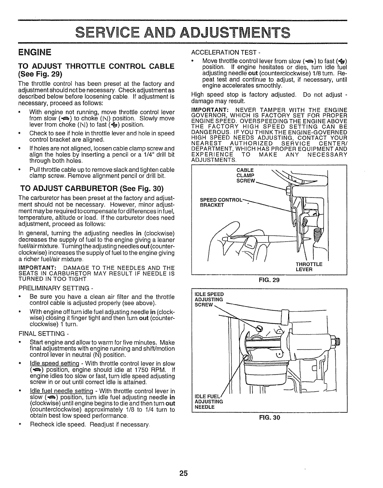
TO REMOVE HOOD AND GRILL ASSEMBLY
(See Fig. 28)
• Raise hood..
oUnsnap headlight wire connector_
= Stand in front of tractor. Grasp hood at sides, tilt toward
engine and lift off of tractor..
• To replace, reverse above procedures.
HOOD
HEADLIGHT
WIRE
CONNECTOR
FIG. 28
24
• _l..... ii,i ,i i, i,l,,i ,, i....
SERVmCE
ENGINE
AND ADJUSTMENTS
TO ADJUST THROTTLE CONTROL CABLE
(See Fig. 29)
The throttle control has been preset at the factory and
adjustment should not be necessary.. Check adjustment as
described below before loosening cable. If adjustment is
necessary, proceed as follows:
•With engine not running, move throttle control Iever
from slow (,_) to choke (1\1) position.. Slowly move
lever from choke (1\1)to fast (,_) position.
oCheck to see if hole in throttle lever and hole in speed
control bracket are aligned°
•If holes are not aligned, loosen cable clamp screw and
align the holes by inserting a pencil or a 1/4" drill bit
through both holes,.
•Pull throttle cable up to remove slack and tighten cable
clamp screw_ Remove alignment pencil or drill bit..
TO ADJUST CARBURETOR (See Fig. 30)
The carburetor has been preset at the factory and adjust-
ment should not be necessary_ However, minor adjust-
ment may be required to compensate fordifferences in fuel,
temperature, altitude or toad. If the carburetor does need
adjustment, proceed as follows:
In general, turning the adjusting needles in (clockwise)
decreases the supply of fuel to the engine giving a leaner
fuel/air mixture° Turning the adjusting needles out (counter-
clockwise) increases the supply of fuet to the engine giving
a richer fueVair mixture,.
IMPORTANT: DAMAGE TO THE NEEDLES AND THE
SEATS IN CARBURETOR MAY RESULT IF NEEDLE IS
TURNED tN TOO TIGHT
PRELIMINARY SE'I-[ING -
•Be sure you have a clean air filter and the throttle
control cable is adjusted properly (see above).
.With engine off turn idte fuel adjusting needle in (clock-
wise) closing it finger tight and then turn out (counter-
clockwise) 1 turn.
FINAL SETTING -
°Start engine and allow to warm for five minutes. Make
final adjustments with engine running and shift/motion
control lever in neutral (N) position.
° Idle speed setting - With throttle control lever in slow
(,€_) position, engine should idle at 1750 RPM. If
engine idles too slow or fast, turn idle speed adjusting
screw in or out until correct idle is attained.
°Idle fuel needle setting - With throttle control lever in
slow (.¢_) position, turn idle fuel adjusting needle in
(clockwise) until engine begins to die and then turn out
(counterclockwise) approximately 1/8 to 1/4 turn to
obtain best low speed performance..
o Recheck idle speed.. Readjust if necessary,
ACCELERATION TEST -
°Move throttle control lever from slow (-€_) to fast ('_s,)
position, If engine hesitates or dies, turn idle fuel
adjusting needle out (counterclockwise) 1/8 turn. Re-
peat test and continue to adjust, if necessary, until
engine accelerates smoothly_
High speed stop is factory adjusted° Do not adjust -
damage may result.
IMPORTANT: NEVER TAMPER WITH THE ENGINE
GOVERNOR, WHICH IS FACTORY SET FOR PROPER
ENGINE SPEED° OVERSPEEDING THE ENGINE ABOVE
THE FACTORY HIGH SPEED SETTING CAN BE
DANGEROUS. IF YOU THINK THE ENGINE-GOVERNED
HIGH SPEED NEEDS ADJUSTING, CONTACT YOUR
NEAREST AUTHORIZED SERVICE CENTER/
DEPARTMENT, WHICH HAS PROPER EQUIPMENT AND
EXPERIENCE TO MAKE ANY NECESSARY
ADJUSTMENTS
CABLE
CLAMP
SCREW
SPEED
BRACKET
FIG. 29
THROTFLE
LEVER
IDLE SPEED
ADJUSTING
SCREW
IDLE FUEL
ADJUSTING
NEEDLE
FIG. 30
25
...................... i
, i,,ll ,,ll ,ll,,,i iill
STORAGE
Immediately prepare your' tractor for storage at the end of
the season or if the tractor' will not be used for 30 days or
more,
CAUTION: Never store the tractor with
gasoline in the tank inside a building
where fumes may reach an open flame
or spark, Allow the engine to cool
before storing in any enclosure.
TRACTOR
Remove mower from tractor for winter storage.. When
mower is to be stored for a period of time, clean it thor-
oughly, remove all dirt, grease, leaves, etc.. Store in a
clean, dry area.
o Clean entire tractor (See"CLEANING" in the Customer
Responsibilities section of this manual)°
• Inspect and replace belts, if necessary (See belt re-
placement instructions in the Service and Adjustments
section of this manual).,
o Lubricate as shown in the Customer Responsibilities
section of this manual.,
. Be sure that all nuts, bolts and screws are securely
fastened.. Inspect moving parts for damage, breakage
and wear., Replace if necessary._
= Touch up atl rusted or chipped paint surfaces; sand
tightly before painting..
BATTERY
•Fut]y charge the battery for storage_
o After a period of time in storage, battery may require
recharging.
• To help prevent corrosion and power leakage during
long periods of storage, battery cables should be
disconnected and battery cleaned thoroughly (see "TO
CLEAN BATTERY AND TERMINALS" in the Cus-
tomer Responsibilities section of this manual)_
° After' cleaning, leave cables disconnected and place
cables where they cannot come incontact with battery
terminal&
° Be sure battery drain tube is securely attache&
• If battery asrernoved from tractor for storage, do not
store battery directly on concrete or damp surfaces..
ENGINE
FUEL SYSTEM
IMPORTANT: IT IS IMPORTANT TO PREVENT GUM
DEPOSITS FROM FORMING IN ESSENTIAL FUEL
SYSTEM PARTS SUCH AS CARBURETOR, FUEL FILTER,
FUEL HOSE, OR TANK DURING STORAGE. ALSO,
EXPERIENCE INDICATES THAT ALCOHOL BLENDED
FUELS (CALLED GASOHOL OR USING ETHANOL OR
METHANOL) CAN ATTRACT MOISTURE WHICH LEADS
TO SEPARATION AND FORMATION OF ACIDS DURING
STORAGE. ACIDIC GAS CAN DAMAGE THE FUEL
SYSTEM OF AN ENGINE WHILE IN STORAGE.
o
o
Drain the fuel tank..
Start the engine and let it run until the fuel lines and
carburetor are empty.,
Never use engine or carburetor cleaner products in the
fuel tank or permanent damage may occur.
Use fresh fuel next season.
NOTE: Fuel stabilizer is an acceptable alternative in
minimizing the formation of fuel gum deposits during stor-
age. Add stabilizer to gasoline in fuel tank or storage
container., Always follow the mix ratio found on stabilizer
container. Run engine at least 10 minutes after' adding
stabilizer to allow the stabilizer to reach the carburetor. Do
not drain the gas tank and carburetor if using fuel stabilizer_
ENGINE OIL
Drain oil (with engine warm) and replace with clean engine
oil. (See "ENGINE" in the Customer Responsibilities
section of this manual).
CYLINDERS
oRemove spark plug(s)..
° Pour one ounce of oil through spark plug hole(s) into
cylinder(s).
• Turn ignition key to "START" position for afew seconds
to distribute oil..
Replace with new spark plug(s),
OTHER
o Do not store gasoline from one season to another.
o Replace your gasoline can if your can starts to rusL
Rust and/or dirt in your gasoline will cause problem&
° If possible, store your' tractor indoors and cover it to
give protection from dust and dirt.,
• Covetyour tractor with a suitable protective cover that
does not retain moisture. Do not use plastic. Plastic
cannot breathe which allows condensation to form and
will cause your tractor to rust.
IMPORTANT: NEVER COVER TRACTOR WHILE ENGINE
AND EXHAUST AREAS ARE STILL WARM.
26

TROUBLESHOOTmNG POINTS
.................. ii i
PROBLEM
Will not start
Hard to start
Engine will not turn over
Engine clicks but wil! not
start
Loss of power
Excessive vibration
CAUSE
t Out of fuel.
2 Engine not "CHOKED" properly
3 Engine flooded.
4, Bad spark plug
5, Dirty air filter.
& Dirty fuel filter.
7Wafer in fuel
8. Loose or damaged wiring
9. Carburetor out of adjustment
i 0, Engine valves out of adjustment
1 Dirty air filter
2 Bad spark plug,
3 Weak or dead battery
4, Dirty fuel filter
5. Stale ordirty fuel
6 Loose or damaged wiring
7. Carburetor out of adjustment
8 Engine valves out of adjustmenL
1 Clutch/brake pedal not depressed
2. Attachment clutch is engaged
3, Weak or dead battery
4 Blown fuse
5, Corroded battery terminals
6, Loose or damaged widng
7,. Faulty ignition switch
8, Faulty solenoid or starter
9 Faulty operator presence switch(as),
1. Weak or dead battery,
2 Corroded battery terminals,
3, Loose or damaged wiring
4 Faulty solenoid or starter,
1 Cutting too much grass/too fast,
2, Throttle in"CHOKE" position.
3 Build-up of grass, leaves and trash under mower,
4, Dirty air fitter_
5. Low oil leveVdirty oif,
6 Fabtlty spark plug
7 Dirty fuel fi{ter
8 Stale or dirty fueI
9 Water in fuel
t0 Spark plug wire loose
tl Dirty engine air screentfins
12. Dirty/clogged muffler,
I3 Loose or damaged wiring
14 Carburetor out of adjustment
15, Engine valves oLit of adjustment,
1, Worn, bent or {oose blade
2. Bent blade mandrel
3, Loose/damaged part(s)
CORRECTION
1 Fill fuel tank
2 See "TO START ENGINE" in Operation section,
3. Wait several minutes before attempting to start
4, Replace spark p}ug,
5Clean/replace air filter
6, Replace fuel filter
7 Drain fuel tank and carburetor, refill tank with fresh
gasoline and replace fuel filter,.
8 Check at{ wiring,,
9, Contact an authorized serv{ce facility
10, Contact an authorized service facility,
t Clean/replace air fitter
2 Replace spark plug
3 Recharge or replace battery
4 Replace fuel filter
5, Drain fuel tank and refill with fresh gasoline
6 Check allwiring
7, Contact an authorized service facil{ty,
8 Contact an authorized service facility,
i i .i..it .luJnlLiLi/ iii i i
1 Depress clutch/brake pedal
2, Disengage attachment clutch,
3 Recharge or replace battery
4 Replace fuse
5 Clean battery terminals
6, Check all wiring
7. Check/replace ignition switch
8. Check/replace sofenoid or starter
9 Contact an authorized service facility
1 Recharge or replace battery,
2, Clean battery terminals
3, Check a_lwiring
4 Check!replace solenoidor starter,
1 Set in "Higher Cut" position/reduce speed,
2, Adjust throttle control
3, Clean underside of mower housing,
4 Clean/replace air filter
5 Check oil level/change oil
6 Clean and regap orchange spark plug
7 Replace fuel filter
8, Drain fuel tank and refill with fresh gasoline
9 Drain fuel tank and carburetor, refill tank with fresh
gasoline and replace tuel filter,
t0 Connect and tighten spark plug wire
11. C{ean engine air screen/fins
12 Clean/replace mufl{er
13 Check all wiring
14 Contact an authorized service facility,
15, Contact an authorized service facility.
1 Replace blade Tighten blade bolt
2 Replace blade mandre_
3. Tighten loose part(s) Replace damaged parts,
27

Engine continues to run
when operator leaves seat
with attachment clutch
engaged
Poor cut - uneven
Mower blades will not
rotate
wit
Poor grass discharge
Headlight(s) not working
(if so equipped)
Battery will not charge
Engine "backfires"
when turning engine
"OFF"
TROUBLESHOO NG POINTS
CAUSE
1.. Faulty operator-safety presence control system
1. Worn, bent or loose blade..
2 Mower deck notlevel.
3 Buildup of grass, leaves, and trash under mower
4 Bent blade mandrel
5.. Clogged mower deck vent holes from buildup of
grass, leaves, and trash around mandrels
1 Obstruction in clutch mechanism
2 Worn/damaged mower drive belt.
CORRECTION
1 Check wiring, switches and connections, If not
corrected, contact an authorized service facility
1 Repiace blade. Tighlen blade bolt.
2 Level mower deck
3 Clean underside of mower' housing
4 Replace blade mandrel
5 Clean around mandrels to open vent hoies
t Remove obstruction
2 Replace mower drive bait
3. Frozen idler pulley
4 Frozen blade mandre!
!., Engine speed too slow
2 Travel speed too fast
3 Wet grass,
4. Mower deck not level
5, Lowtuneven tire air pressure
6 Worn, bent orloose blade
3 Replace idler pulley.
4 Replace blade mandrel
1 Place throttle controf in "FAST" position.
2 Shift to slower speed.
3 Allow grass todry before mowing..
4 Level mower deck
5 Check tires for proper air pressure.
6 Replace/sharpen blade.. Tighten blade bolt.
7.. Buildup of grass, leaves and trash under mower
8 Mower drive beltworn..
9 Btades improperly installed
10 Improper blades used.
11. Clogged mower deck vent holes from buildup of
grass, leaves, and trash around mandrels
ww ...........
t Switch is "OFF"
2 Bulb(s) burned out..
3 Faulty light switch..
4. Loose or damaged wiring
5. Blown fuse
1 Bad battery cell(s)
2. Poor cable connections
3.. Faulty regulator (if so equipped).
4. Faulty alternator.
1,. Engine throttle control not set at "SLOW"
position for 30 seconds before stopping engine
7 Clean underside of mower housing,
8 Replace mower drive bett
9 Reinstall blades sharp edge down
10 Replace with blades listed in this manual,
1t Clean around mandrels to open vent holes
1
2
3
4
5
t
2
Turn swilch "ON".
Replace bulb(s).
Check/replace light switch..
Check wiring and connections
Replace fuse.
3
4.
Replace battery
Check/clean all connections
Replace regulator
Replace alternator
1. Move throttle control to "SLOW" position and attow
to idle for 30 seconds before stopping engine
28
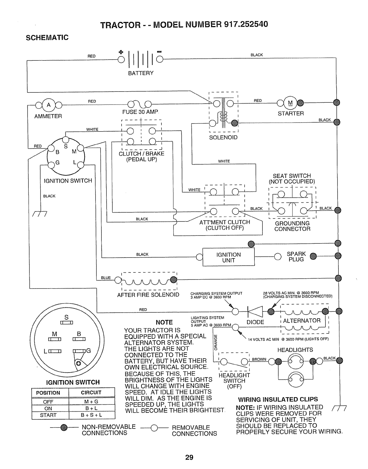
TRACTOR -- MODEL NUMBER 917.252540
SCHEMATIC
RED ©m
11o
_ATTERY
8LACK
AMMETER
RED
FUSE 30 AMP.
r .......
I t- 1
WHITE
t IGNITION SWITCH
la-@ , 0 Ii f
t
' ! C_--
LJ
CLUTCH /BRAKE
(PEDAL UP)
BLACK
I
t I
}
SOLENOID
WH1TE
STARTER
BLACK
RED
SEAT SWITCH
I _1
AFTER FIRE SOLENOID
I - I
WHITE T'--_
IiI
I L I
_AiLr_-EN'r CUJTOH "]
L (CLUTCH OFF) J
BLACK
@
(_ IGNITIONUNIT
(NOT OCCUPIED)
GROUNDING
CONNECTOR
CHARGING SYSTEM OUTPUT
3 AMP DC @ 3600 RPM
SPARK
PLUG
28 VOLTS AC MiN. @ 3600 RPM
(CHARGING SYSTEM DISCONNECTED)
RED
SLIGHTING SYSTEM
NOTE OUTPUT DIODE i ALTERNATOR
5 AMP AC @ 3600 R.PM_.F-__
YOUR TRACTOR 1S ,_
M B \/
EQUIPPED WITH ASPECIAL !_ ,4VOLTSACM,N_3600RPM(LtGHTSOF_')
[ICCt3 EECZ] ALTERNATOR SYSTEM IQ
L[zzzz] THE LIGHTS ARE NOT !_ HEADLIGHTS
CONNECTED TO THE I _....... _
BATTERY, BUT HAVE THEIR _ __
OWNELECTRICALSOURCE,;____ _'i v T _J T -
BECAUSE OF THIS, THE 14E-ADLK_T !_ 1
BRIGHTNESS OF THE LIGHTS SWtT_,.:I L----{O O)-J
IGNITION SWITCH
........ WILL CHANGE WITH ENGINE (OFF)
POSITION CIRCUIT SPEED. AT IDLE THE LIGHTS
............... ......................................... :: WILL DIM. AS THE ENGINE IS WIRING INSULATED CLIPS
OFF M + G SPEEDED UP, THE LIGHTS
ON " '""' ...................B'+'"'L _ " WILL BECOME THEIR BRIGHTEST. NOTE: IF WIRING INSULATED /-_
.... START B + S + L CLIPS WERE REMOVED FOR
......... SERVICING OF UNIT, THEY
NON-REMOVABLE _ REMOVABLE SHOULD BE REPLACED TO
CONNECTIONS CONNECTIONS
7
PROPERLY SECURE YOUR WIRING°
29
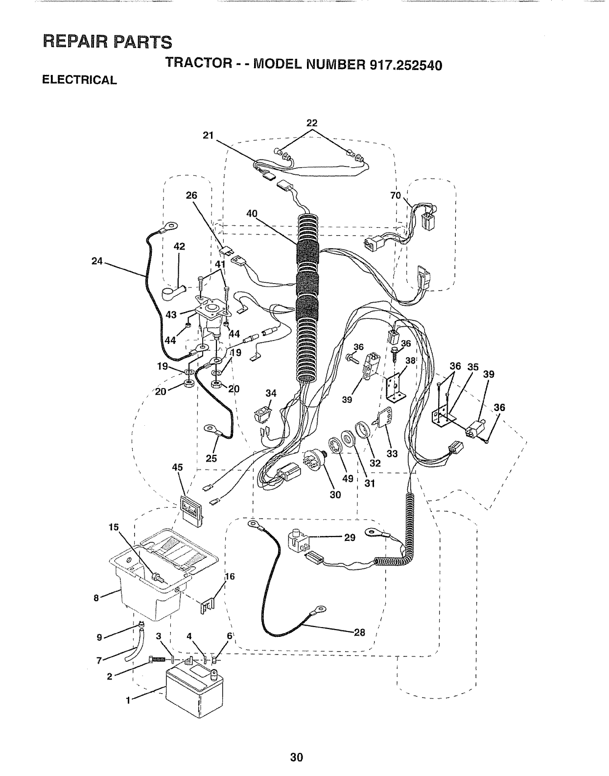
REPAIR PARTS
TRACTOR - - MODEL NUMBER 917.252540
ELECTRICAL
21
22
41
36 35
34
\
39
32
' 31
I
30
I I
i
\
39
,,36
-.,/
/
/
/
/
/
/
/
3O
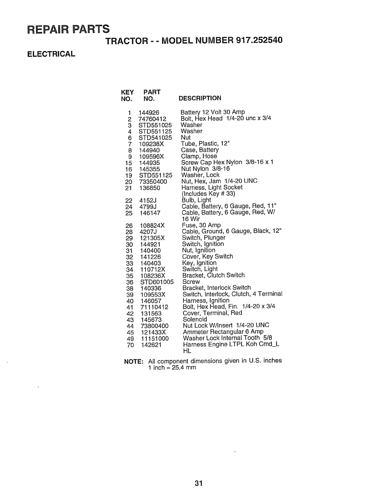
REPAIR PARTS
TRACTOR --MODEL NUMBER 917.252540
ELECTRICAL
KEY PART
NO. NO° DESCRIPTION
1 144926 Battery 12 Volt 30 Amp
2 74760412 Bolt, Hex Head 1/4-20 unc x 3/4
3 STD551025 Washer
4 STD551125 Washer
6 STD541025 Nut
7 109238X Tube, Plastic, 12"
8 144940 Case, Battery
9 109596X Clamp, Hose
15 144935 Screw Cap Hex Nylon 3/8-16 x 1
16 145355 Nut Nylon 3/8-16
19 STD55t125 Washer, Lock
20 73350400 Nut, Hex, Jam 1/4-20 UNC
21 136850 Harness, Light Socket
(Includes Key # 33)
22 4152J Bulb, Light
24 4799J Cable, Battery, 6 Gauge, Red, 11"
25 146147 Cable, Battery, 6 Gauge, Red, W/
16 Wit
26 !08824X Fuse, 30 Amp
28 4207J Cable, Ground, 6 Gauge, Black, 12"
29 121305X Switch, Plunger
30 144921 Switch, ignition
31 140400 Nut, Ignition
32 141226 Cover, Key Switch
33 't40403 Key, Ignition
34 110712X Switch, Light
35 108236X Bracket, Clutch Switch
36 STD601005 Screw
38 140336 Bracket, Interlock Switch
39 109553X Switch, Interlock, Clutch, 4 Terminal
40 146057 Harness, Ignition
41 71110412 Bolt, Hex Head, Finn 1/4-20 x 3/4
42 131563 Cover, Terminal, Red
43 145673 Solenoid
44 73800400 Nut LockW/Insert 1/4-20 UNC
45 121433X Ammeter Rectangular 6 Amp
49 11151000 Washer Lock internal Tooth 5/8
70 142621 Harness Engine LTPL Koh Cmd_L
HL
NOTE: All component dimensions given in UoS. inches
1 inch = 25.4 mm
31
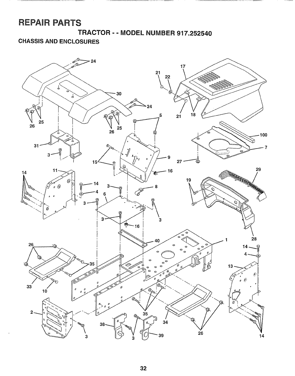
REPAnR PARTS
TRACTOR-- MODEL NUMBER 917.252540
CHASSIS AND ENCLOSURES
14
26
33 10
26 25 I
5 21 18
It
i
I
I
19
26
29
28
14
32
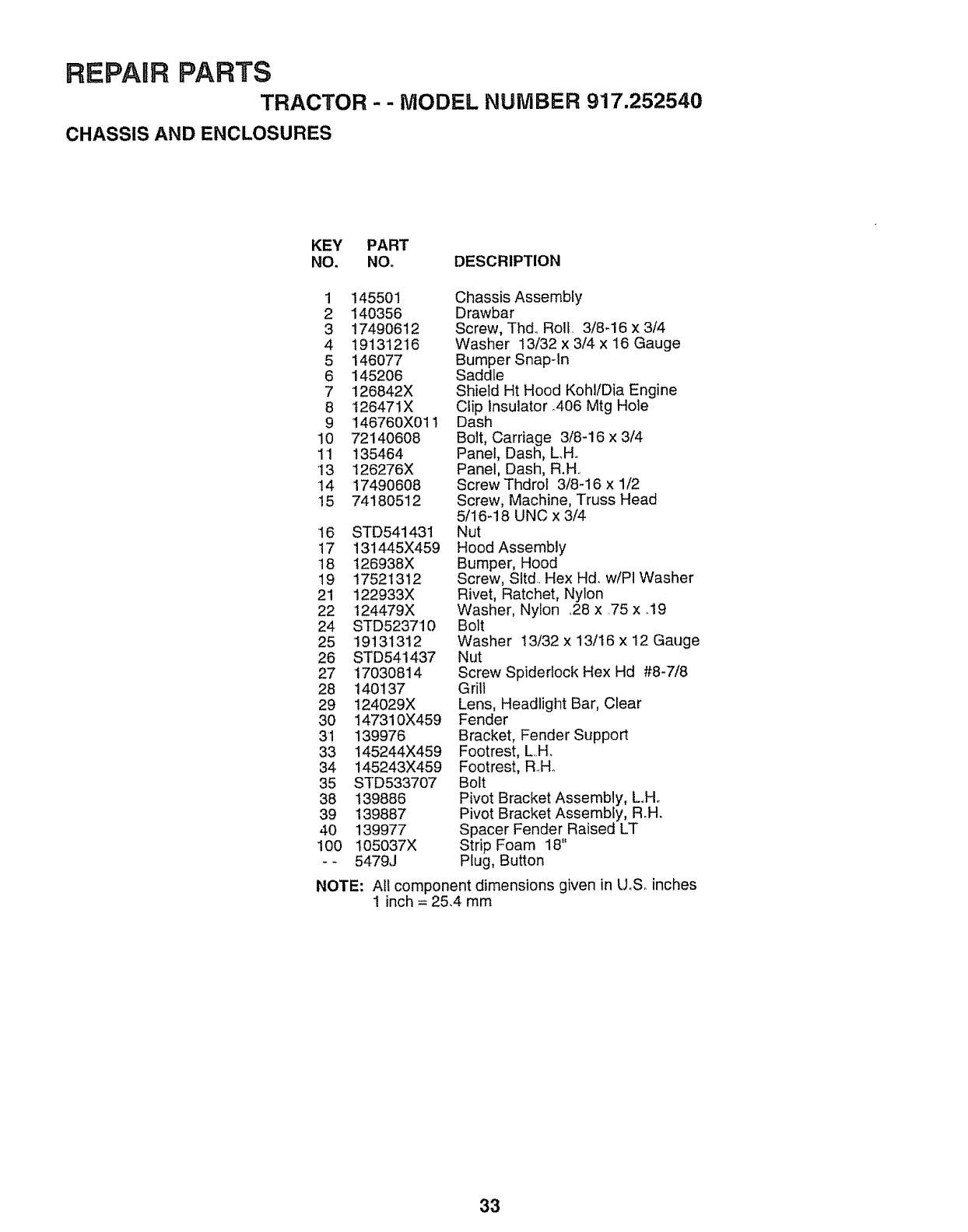
REPAIR PARTS
TRACTOR - - MODEL NUMBER 917.252540
CHASSIS AND ENCLOSURES
KEY PART
NO. NO. DESCRIPTION
1 145501 Chassis Assembly
2 140356 Drawbar
3 17490612 Screw, Thd. Roll. 3/8-16 x 3/4
4 19131216 Washer 13/32 x 3/4 x 16 Gauge
5 146077 Bumper Snap-In
6 145206 Saddle
7 126842X Shield Ht Hood Kohl/Dia Engine
8 126471X Clip Insulator .406 Mtg Hole
9 146760X011 Dash
10 72140608 Bolt, Carriage 3/8-16 x 3/4
11 135464 Panel, Dash, L_H_
•13 126276X Panel, Dash, R.H..
14 17490608 ScrewThdrot 3/8-16 x 1/2
15 74180512 Screw, Machine, Truss Head
5/16-18 UNC x 3/4
16 STD541431 Nut
17 131445X459 Hood Assembly
18 126938X Bumper, Hood
19 17521312 Screw, Slid. Hex Hd_ w/PI Washer
21 122933X Rivet, Ratchet, Nylon
22 124479X Washer, Nylon ,28 x .75 x ..19
24 STD523710 Bolt
25 19131312 Washer 13/32 x 13/t6 x 12 Gauge
26 STD541437 Nut
27 17030814 Screw Spiderlock Hex Hd #8-7/8
28 140137 Grill
29 124029X Lens, Headlight Bar, Clear
30 147310X459 Fender
31 139976 Bracket, Fender Support
33 145244X459 Footrest, L..H_
34 145243X459 Footrest, R.H..
35 STD533707 Bolt
38 139886 Pivot Bracket Assembly, L.H..
39 139887 Pivot Bracket Assembly, R_H.
40 139977 Spacer Fender Raised LT
100 105037X Strip Foam 18"
-- 5479J Plug, Button
NOTE: All component dimensions given in U.So inches
1inch = 25.4 mm
33
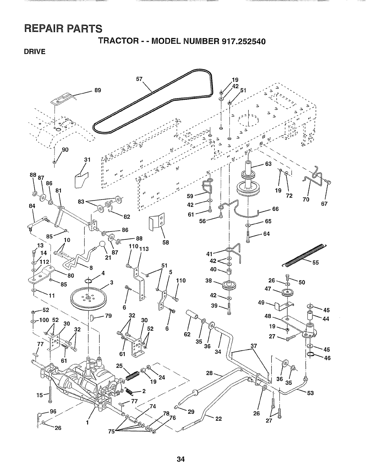
REPAIR PARTS
TRACTOR -- MODEL NUMBER 917,252540
DRIVE
19
5
i10
662
35 36 34 37
67
26
53
75
34
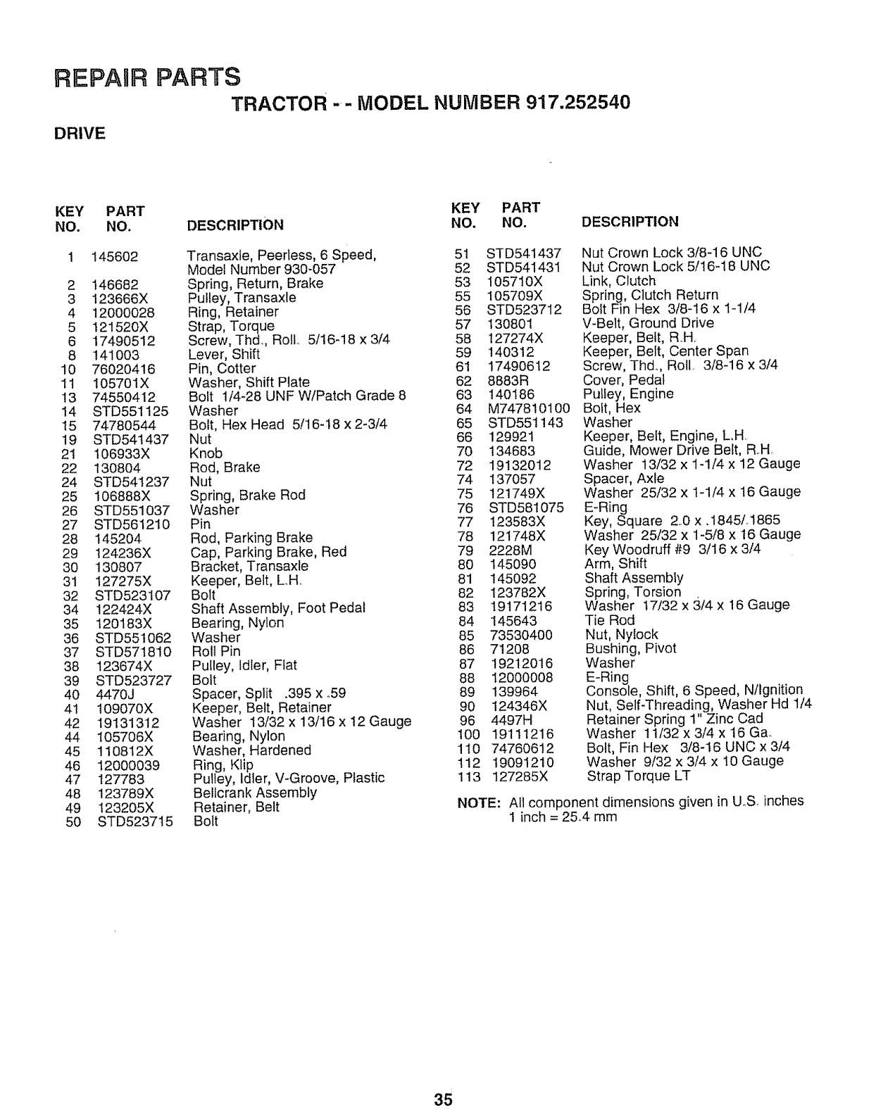
REPAIR
DRIVE
PARTS
TRACTOR -- MODEL NUMBER 917.252540
KEY PART
NO. NO.
1 145602
2 146682
3 123666X
4 12000028
5 121520X
6 17490512
8 141003
10 76020416
11 105701X
!3 74550412
14 STD551125
15 74780544
19 STD541437
21 106933X
22 130804
24 STD541237
25 106888X
26 STD551037
27 STD5612!0
28 145204
29 124236X
30 130807
31 127275X
32 STD523107
34 !22424X
35 t20183X
36 STD551062
37 STD571810
38 123674X
39 STD523727
40 4470J
41 109070X
42 19131312
44 105706X
45 110812X
46 12000039
47 127783
48 123789X
49 t23205X
50 STD523715
KEY PART
DESCRIPTION NO. NO. DESCRIPTION
Transaxle, Peerless, 6 Speed, 51 STD541437
Model Number 930-057 52 STD541431
Spring, Return, Brake 53 105710X
Pulley, Transaxle 55 105709X
Ring, Retainer 56 STD523712
Strap, Torque 57 130801
Screw, Thd., RoE 5/16-18 x 3/4 58 127274X
Lever, Shift 59 140312
Pin, Cotter 61 17490612
Washer, Shift Plate 62 8883R
Bolt 1/4-28 UNF W/Patch Grade 8 63 140186
Washer 64 M747810100
Bolt, Hex Head 5/16-18 x 2_3/4 65 STD551143
Nut 66 129921
Knob 70 134683
Rod, Brake 72 19132012
Nut 74 !37057
Spring, Brake Rod 75 !21749X
Washer 76 STD581075
Pin 77 123583X
Rod, Parking Brake 78 121748X
Cap, Parking Brake, Red 79 2228M
Bracket, Transaxle 80 145090
Keeper, Belt, L_H. 81 145092
Bolt 82 123782X
Shaft Assembly, Foot Pedal 83 19171216
Bearing, Nylon 84 145643
Washer 85 73530400
Roll Pin 86 71208
Pulley, Idler, Flat 87 19212016
Bolt 88 12000008
Spacer, Split .395 x °59 89 139964
Keeper, Belt, Retainer 90 124346X
Washer 13/32 x 13/16 x 12 Gauge 96 4497H
Bearing, Nylon !00 19111216
Washer, Hardened 1t0 74760612
Ring, Klip 112 19091210
Pulley, Idler, V-Groove, Plastic 113 t27285X
Betlcrank Assembly
Retainer, Belt
Bolt
Nut Crown Lock 3/8-16 UNC
Nut Crown Lock 5/16-18 UNC
Link, Clutch
Spring, Clutch Return
Bolt Fin Hex 318-16 x I-1/4
V-Belt, Ground Drive
Keeper, Belt, R.H,
Keeper, Belt, Center Span
Screw, Thd. Roll 3/8-16 x 3/4
Cover, Pedal
PuIfey, Engine
Bolt, Hex
Washer
Keeper, Belt, Engine, L.H
Guide, Mower Drive Belt, RH,
Washer 13/32 x 1-1/4 x 12 Gauge
Spacer, Axle
Washer 25/32 x 1-1/4 x 16 Gauge
E-Ring
Key, Square 20 x .1845L1865
Washer 25/32 x 1-5/8 x 16 Gauge
Key Woodruff #9 3/16 x 3/4
Arm, Shift
Shaft Assembly
Spring, Torsion
Washer 17/32 x 3/4 x 16 Gauge
Tie Rod
Nut, Ny!ock
Bushing, Pivot
Washer
E-Ring
Console, Shift, 6 Speed, Ntlgnition
Nut, Self-Threading, Washer Hd 1/4
Retainer Spring 1" Zinc Cad
Washer 11!32 x 3/4 x 16 G&
Bolt, Fin Hex 3/8-16 UNC x 3/4
Washer 9/32 x 3/4 x 10 Gauge
Strap Torque LT
NOTE: All component dimensions given in U..S. inches
1 inch = 25.4 mm
35
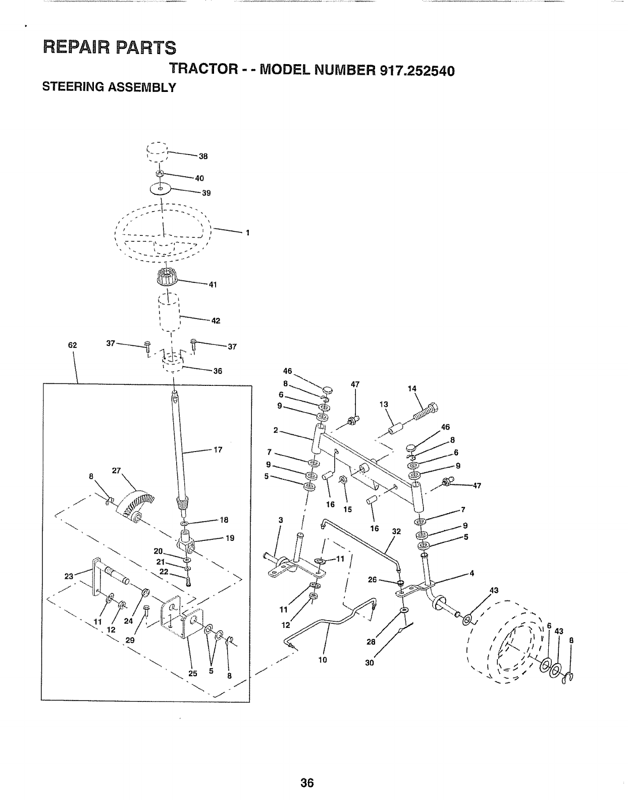
REPAIR PARTS
TRACTOR --MODEL NUMBER 917.252540
STEERING ASSEMBLY
b!-,
t I
I
I
I
117
46
47
12
16 32
26
28
30
t
I
I
\
\
43
36
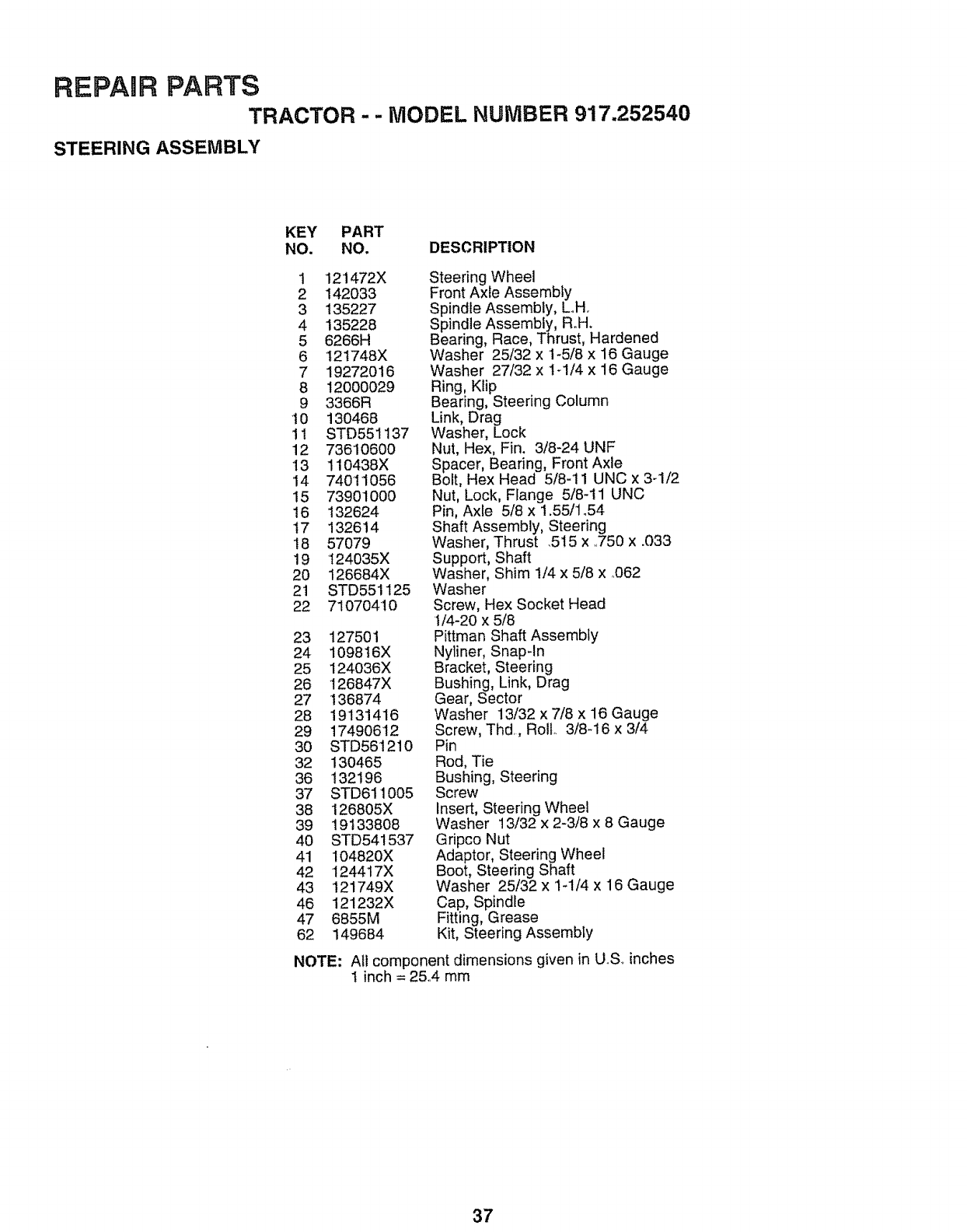
REPAIR PARTS
TRACTOR - -MODEL NUiVIBER 917.252540
STEERING ASSEMBLY
KEY PART
NO. NO. DESCRIPTION
1 121472X
2 142033
3 135227
4 135228
5 6266H
6 121748X
7 19272O16
8 12000029
9 3366R
10 130468
11 STD551137
12 73610600
13 110438X
'14 74011056
15 73901000
16 132624
17 132614
18 57079
19 124035X
2O 126684X
21 STD551125
22 71070410
23 127501
24 109816X
25 124036X
26 126847X
27 136874
28 19131416
29 17490612
3O STD561210
32 130465
36 132196
37 STD611005
38 126805X
39 19133808
4O STD541537
41 104820X
42 124417X
43 121749X
46 121232X
47 6855M
62 149684
Steering Wheel
Front Axte Assembly
Spindte Assembly, Loll.
Spindle Assembly, R.H.
Bearing, Race, Thrust, Hardened
Washer 25/32 x 1-5/8 x 16 Gauge
Washer 27/32 x 1_1/4 x 16 Gauge
Ring, Klip
Bearing, Steering Column
Link, Drag
Washer, Lock
Nut, Hex, Fin. 3/8-24 UNF
Spacer, Bearing, Front Axle
Bolt, Hex Head 5/8-11 UNC x 3-1/2
Nut, Lock, Flange 5/8-11 UNC
Pin, Axle 5/8 x 1.55/1.54
Shaft Assembly, Steering
Washer, Thrust .515 x ,.750 x .033
Support, Shaft
Washer, Shim 1/4 x 5/8 x .062
Washer
Screw, Hex Socket Head
1/4-20 x 5/8
Pittman Shaft Assembly
Nyliner, Snap-In
Bracket, Steering
Bushing, Link, Drag
Gear, Sector
Washer 13/32 x 7/8 x 16 Gauge
Screw, Thd, Roll 3/8-16 x 3/4
Pin
Rod, Tie
Bushing, Steering
Screw
Insert, Steering Wheel
Washer 13/32 x 2-3/8 x 8 Gauge
Gripco Nut
Adaptor, Steering Wheel
Boot, Steering Shaft
Washer 25/32 x 1-1/4 x 16 Gauge
Cap, Spindle
Fitting, Grease
Kit, Steering Assembty
NOTE: All component dimensions given in U..Soinches
I inch = 25..4 mm
37
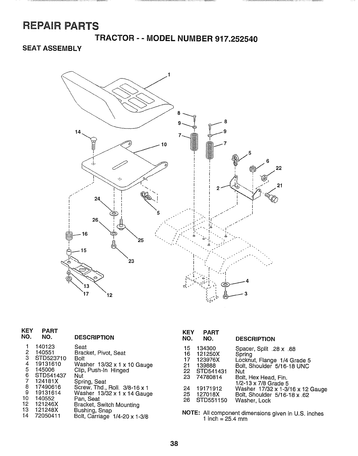
REPABR PARTS
TRACTOR -- MODEL NUMBER 917.252540
SEAT ASSEMBLY
115
"_\ 13 _.
17 12
23
5
10 ®6
21
KEY
NO.
!
2
3
4
5
6
7
8
9
10
12
t3
14
PART
NO.
140123
140551
STD523710
19131610
145006
STD541437
124181X
17490616
19131614
140552
121246 X
121248 X
72050411
DESCRIPTION
Seat
Bracket, Pivot, Seat
Bolt
Washer 13/32 x 1 x 10 Gauge
Clip, Push-ln Hinged
Nut
Spring, Seat
Sc_ew, Thd., RoE 3/8-!6 x 1
Washer 13/32 x I x i4 Gauge
Pan, Seat
Bracket, Switch Mounting
Bushing, Snap
Bolt, Carriage 1/4-20 x 1-3/8
KEY PART
NO. NO. DESCRIPTION
15 134300 Spacer, Split .28 x ..88
16 121250X Spring
17 123976X Locknut, Flange 1/4 Grade 5
21 139888 Bolt, Shoulder 5/16-18 UNC
22 STD541431 Nut
23 74780814 Bolt, Hex Head, Fin.
1/2-13 x 7/8 Grade 5
24 19171912 Washer 17/32 x 1-3/t6 x t2 Gauge
25 127018X Bolt, Shoulder 5/16-18 x .62
26 STD551150 Washer, Lock
NOTE: Atl component dimensions given in U.S. inches
1 inch = 25.4 mm
38
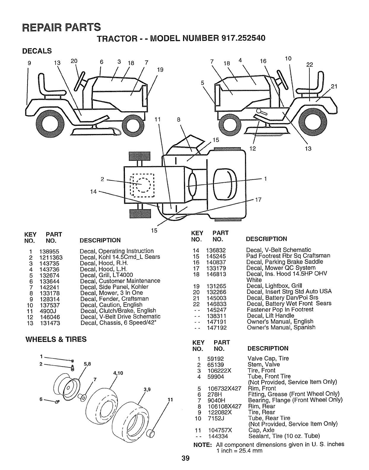
REPAUR
DECALS
9 13
PARTS
TRACTOR - -MODEL NUMBER 917.252540
20 6 3 18 7 7 18 4 16
/ 19
10 22
21
11 8
2
14
12
17
13
KEY PART
NO. NO,
1 138955
2 1211363
3 143735
4 143736
5 132674
6 133644
7 142241
8 133178
9 128314
10 137537
11 4900J
12 146046
13 131473
15 KEY PART
DESCRIPTION NO, NO. DESCRIPTION
Decal
Decal
Decal
Decal
Decal
Decal
Decal
Decal
Decal
Decal
Decal
Decal,
Decal,
Operating Instruction 14
Koh114.5Cmd_L Sears 15
Hood, R_H,. 16
Hood, L.H,, 17
Grill, LT4000 18
Customer Maintenance
Side Panel, Kohler 19
Mower, 3 In One 20
Fender, Craftsman 21
Caution, English 22
Clutch/Brake, English - -
V-Belt Drive Schematic - -
Chassis, 6 Speed/42" - -
WHEELS & TIRES
5,8
74,10
;,9
11
136832
145245
140837
133179
146813
131265
132266
145003
146833
145247
138311
147191
147192
Decal, V-Belt Schematic
Pad Footrest Rbr Sq Craftsman
Decal, Parking Brake Saddle
Decal, Mower QC System
Decal, Ins,. Hood 14.5HP OHV
White
Decal, Lightbox, Grill
Decal, Insert Strg Std Auto USA
Decal, Battery Dan/Poi Srs
Decal, Battery Wet Front Sears
Fastener Pop In Footrest
Decal, Lift Handle
Owner's Manual, English
Owner's Manual, Spanish
39
KEY PART
NO. NO, DESCRIPTION
1 59192
2 65139
3 106222X
4 59904
5
6
7
8
9
10
106732X427
278H
9040H
106108X427
122082X
7152J
11
NOTE:
104757X
144334
Valve Cap, Tire
Stem, Valve
Tire, Front
Tube, Front Tire
(Not Provided, Service item Only)
Rim, Front
Fitting, Grease (Front Wheel Only)
Bearing, Flange (Front Wheel Only)
Rim, Rear
Tire, Rear
Tube, Rear Tire
(Not Provided, Service Item Only)
Cap, Axle
Sealant, Tire (10 ozo Tube)
Atl component dimensions given in U oS inches
1inch = 25,4 mm
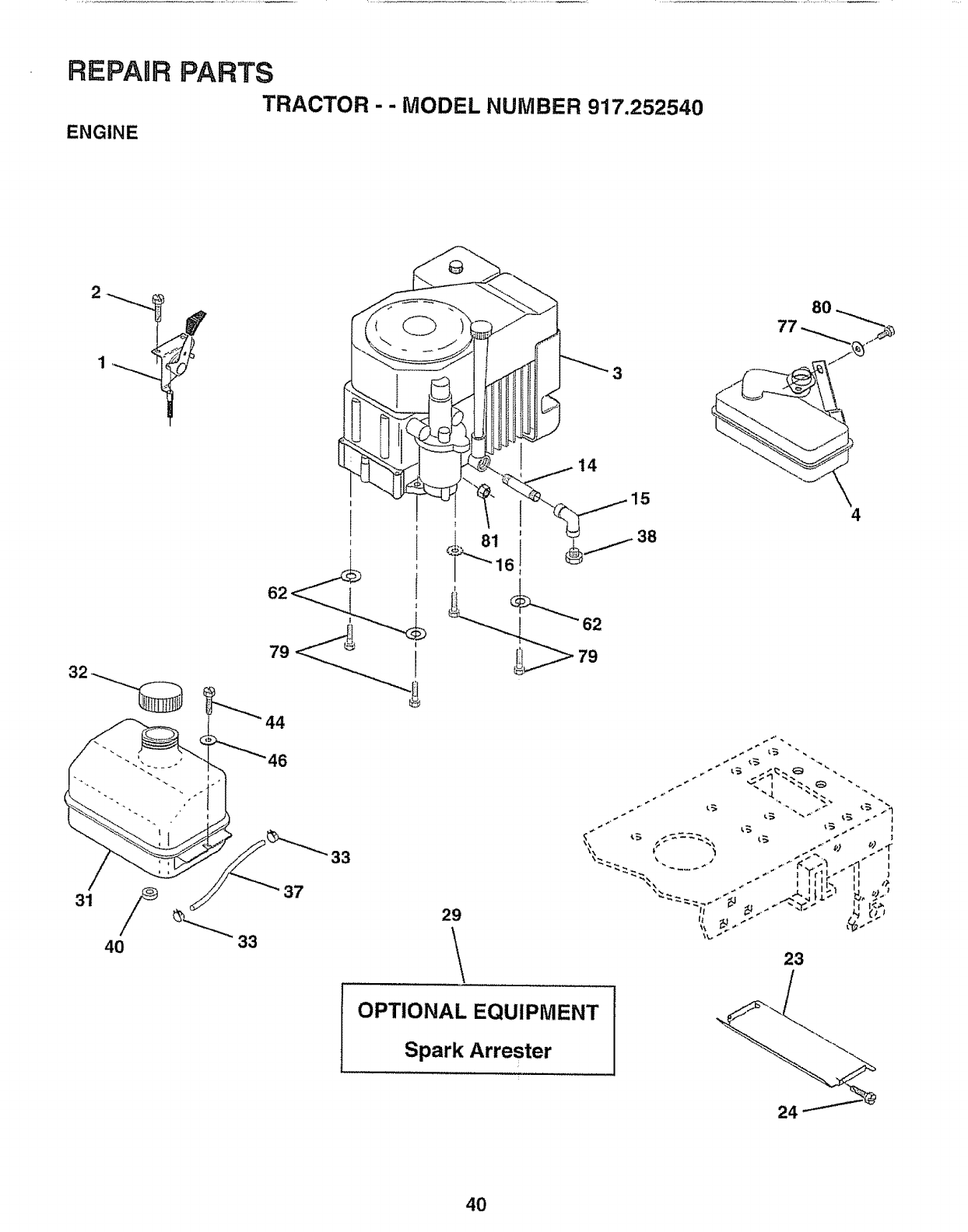
REPAIR PARTS
TRACTOR - - MODEL NUMBER 917.252540
ENGINE
31 37
33
14
15
6
4
29
\23
OPTIONAL EQUIPMENT
Spark Arrester
40
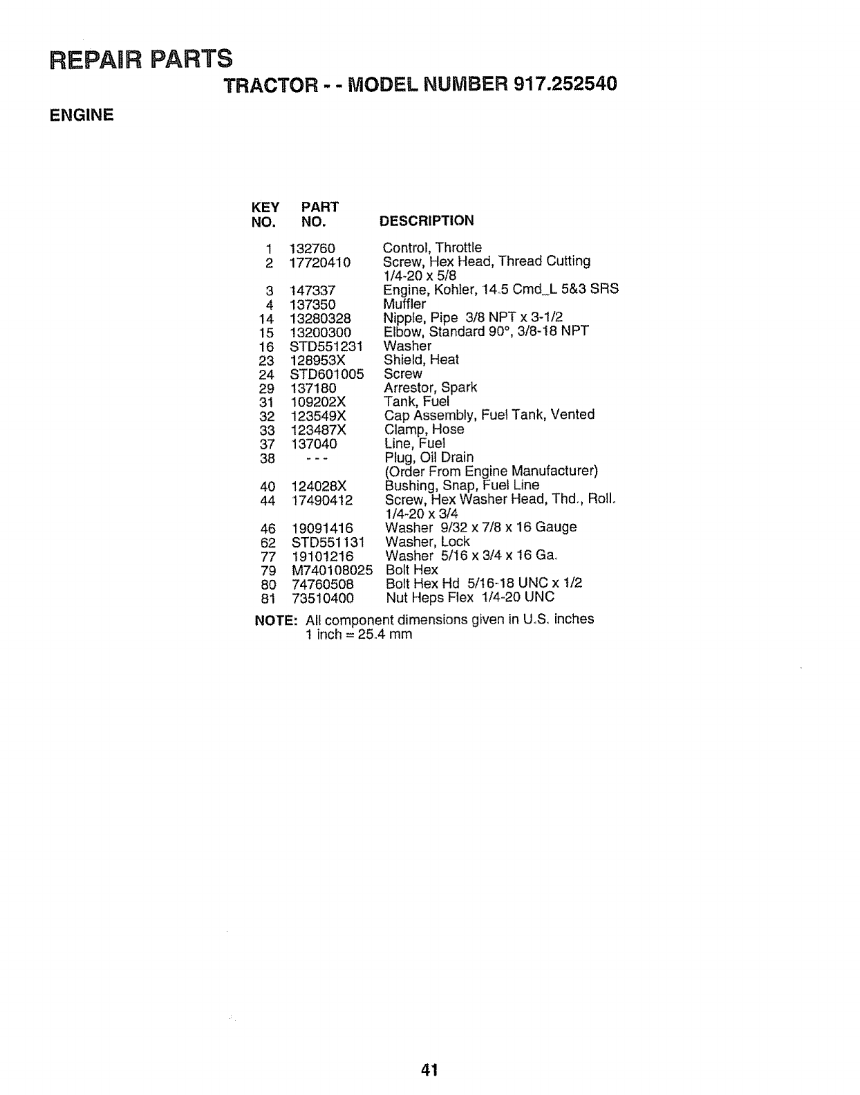
REPAURPARTS
TRACTOR -- MODEL NUMBER 917.252540
ENGINE
KEY PART
NO. NO. DESCRIPTION
1
2132760
17720410
3 147337
4 137350
14 13280328
15 13200300
16 STD551231
23 128953X
24 STD601005
29 137180
31 109202X
32 123549X
33 123487X
37 137040
38 ---
40 124028X
44 17490412
46 19091416
62 STD551131
77 19101216
79 M740i08025
80 747605O8
81 735104O0
NOTE:
Control, Throttle
Screw, Hex Head, Thread Cutting
1/4-20 x 5/8
Engine, Kohfer, 14.5 Cmd_L 5&3 SRS
Muffler
Nipple, Pipe 3/8 NPT x 3-1/2
Elbow, Standard 90°, 3/8-t8 NPT
Washer
Shield, Heat
Screw
Arrestor, Spark
Tank, Fuel
Cap Assembly, Fuel Tank, Vented
Clamp, Hose
Line, Fuel
Plug, Oil Drain
(Order From Engine Manufacturer)
Bushing, Snap, Fuel Line
Screw, Hex Washer Head, Thdo, Roll.
1/4-20 x 3/4
Washer 9/32 x 7/8 x 16 Gauge
Washer, Lock
Washer 5/16 x 3/4 x 16 Ga,.
Bolt Hex
Bolt Hex Hd 5/t6-18 UNC x 1/2
Nut Heps Flex 1/4-20 UNC
All component dimensions given in U.S,. inches
1 inch = 25.4 mm
41
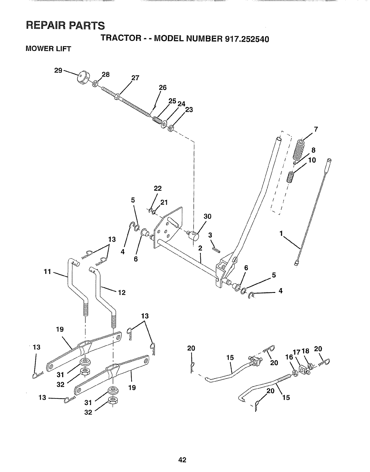
REPAIR PARTS
TRACTOR - - MODEL NUMBER 917.252540
MOWER LIFT
28 27
/26
24 23
11
13
4
22
5 21
6
30
\
6
8
i
!
i ! II
i I
5
19
_13
32
1
32
19
13
20
15 20 161718
15
2O
42
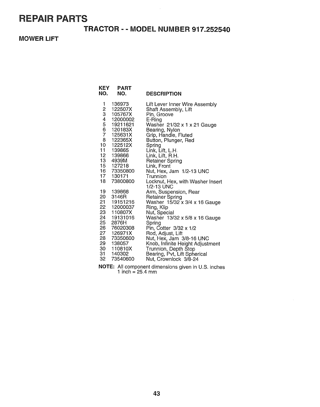
REPAIR PARTS
TRACTOR - - MODEL NUMBER 917.252540
MOWER LIFT
KEY PART
NO. NO. DESCRIPTION
1 136973 Lift Lever InnerWire Assembly
2 122507X Shaft Assembly, Lift
3 105767X Pin, Groove
4 12000002 E-Ring
5 19211621 Washer 21/32x 1 x21 Gauge
6 120183X Bearing, Nylon
7 125631X Grip, Handle, Fluted
8 122365X Button, Plunger, Red
10 1225!2X Spring
11 !39865 Link, Lift, LH.
12 139866 Link, Lift, R..Ho
13 4939M Retainer Spring
15 127218 Link, Front
i6 73350800 Nut, Hex, Jam 1/2-13 UNC
17 130171 Trunnion
18 73800800 Locknut, Hex, with Washer Insert
1/2-13 UNC
19 139868 Arm, Suspension, Rear
20 3t46R Retainer Spring
21 19151216 Washer 15/32 x 3/4 x 16 Gauge
22 12000037 Ring, Klip
23 110807X Nut, Special
24 19131016 Washer t3/32 x 5/8 x 16 Gauge
25 2876H Spring
26 76020308 Pin, Cotter 3/32 x 1/2
27 126971X Rod, Adjust, Lift
28 73350600 Nut, Hex, Jam 3/8-16 UNC
29 138057 Knob, infinite Height Adjustment
30 110810X Trunnion, Depth Stop
31 140302 Bearing, Pvt, Lift Spherical
32 73540600 Nut, Crownlock 3/8-24
NOTE: All component dimensions given in U.S_ inches
1 inch = 25.4 mm
43
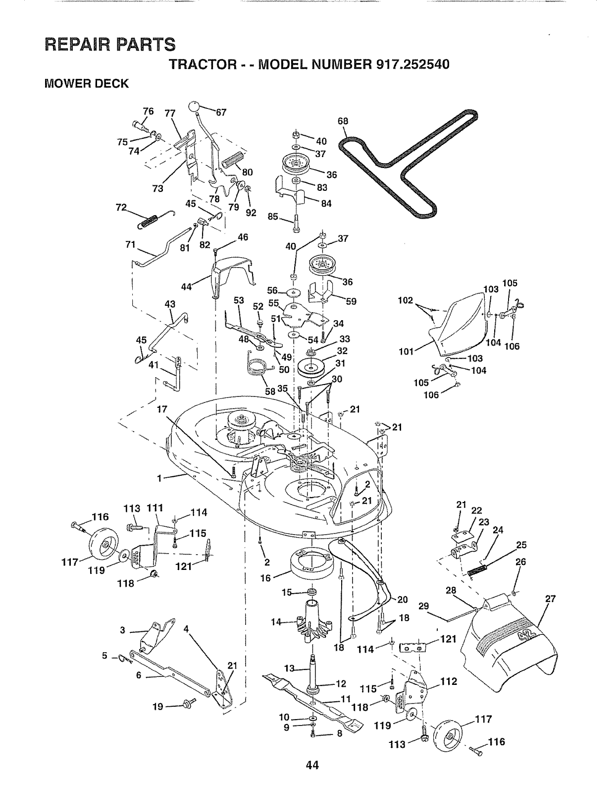
REPAIR PARTS
TRACTOR - - MODEL NUMBER 917.252540
MOWER DECK
7574
76 77
73
4O
68
34
33
32
102
_"_"-104
105/ ._
106"
105
106
\2
23 24
28
29
18
44
27
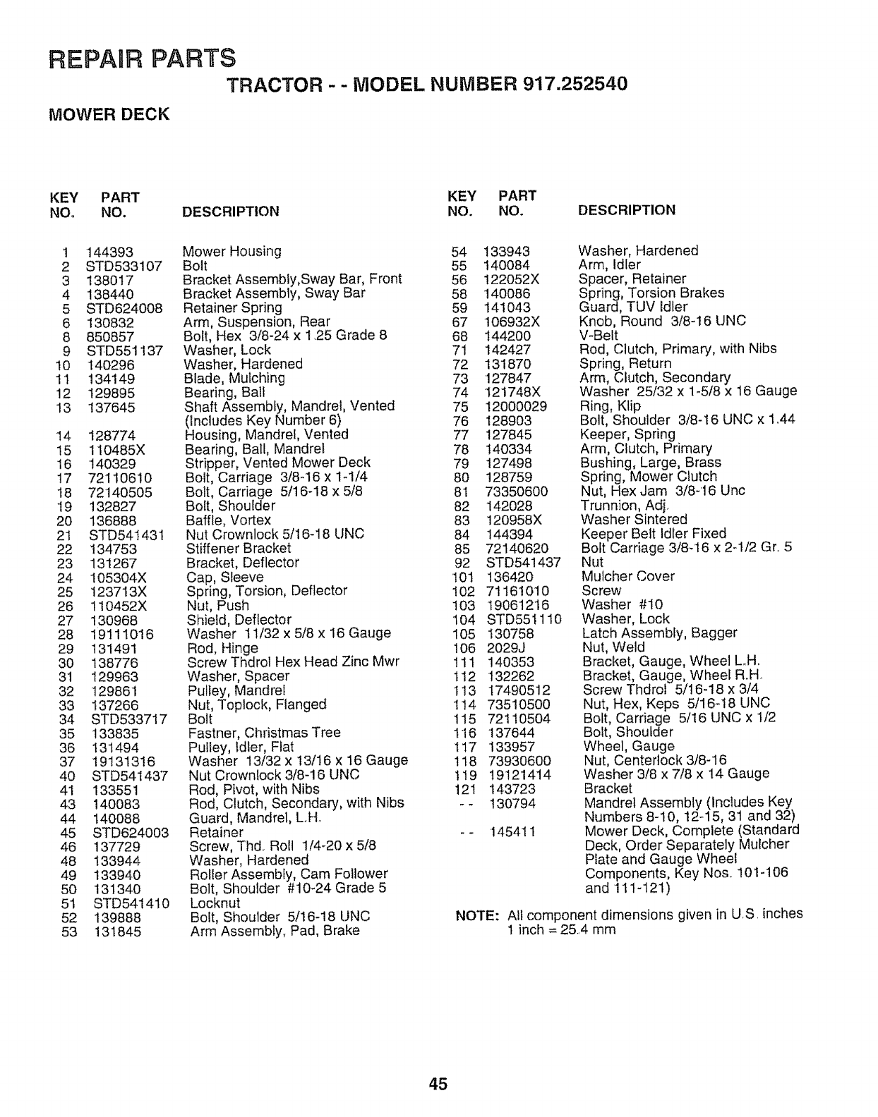
REPAnR PARTS
TRACTOR - - MODEL NUMBER 917.252540
MOWER DECK
KEY PART KEY PART
NO. NO. DESCRIPTION NO. NO. DESCRIPTION
1 144393
2 STD533107
3 138O17
4 138440
5 STD624008
6 130832
8 85O857
9 STD551137
10 140296
11 134149
12 129895
13 137645
14 128774
15 110485X
16 140329
17 72110610
18 72140505
19 132827
20 136888
21 STD54t43I
22 134753
23 131267
24 105304X
25 123713X
26 110452X
27 130968
28 19111016
29 131491
30 138776
31 129963
32 129861
33 137266
34 STD533717
35 133835
36 131494
37 19131316
40 STD541437
41 133551
43 140083
44 140088
45 STD624003
46 137729
48 133944
49 133940
50 131340
51 STD5414t0
52 139888
53 131845
Mower Housing 54
Bolt 55
Bracket Assembly,Sway Bar, Front 56
Bracket Assembly, Sway Bar 58
Retainer Spring 59
Arm, Suspension, Rear 67
Bolt, Hex 3/8-24 x 1,25 Grade 8 68
Washer, Lock 71
Washer, Hardened 72
Blade, Mulching 73
Bearing, Ball 74
Shaft Assembly, Mandrel, Vented 75
(Includes Key Number 6) 76
Housing, Mandrel, Vented 77
Bearing, Ball, Mandrel 78
Stripper, Vented Mower Deck 79
Bolt, Carriage 3/8-16 x 1-1/4 80
Bolt, Carriage 5/16-18 x 5/8 8!
Bolt, Shoulder 82
Baffle, Vortex 83
Nut Crownlock 5/16-18 UNC 84
Stiffener Bracket 85
Bracket, Deflector 92
Cap, Sleeve 101
Spring, Torsion, Deflector 102
Nut, Push 103
Shield, Deflector 104
Washer 11/32 x 5/8 x 16 Gauge 105
Rod, Hinge 106
Screw Thdrol Hex Head Zinc Mwr 111
Washer, Spacer 112
Pulley, Mandrel 113
Nut, Toplock, Flanged 1t4
Bolt 115
Fastner, Christmas Tree 1I 6
Pulley, Idler, Fiat 1t7
Washer 13/32 x 13/16 x 16 Gauge 118
Nut Crowntock 3/8-16 UNC 119
Rod, Pivot, with Nibs 121
Rod, Clutch, Secondary, with Nibs - -
Guard, Mandrel, L,H.
Retainer - -
Screw, Thd, Roll 1/4-20 x 5/8
Washer, Hardened
Roller Assembly, Cam Follower
Bolt, Shoulder #10-24 Grade 5
Locknut
Bolt, Shoulder 5/16-18 UNC
Arm Assembly, Pad, Brake
133943
140084
122052X
140086
141043
106932X
144200
142427
131870
127847
121748X
12O00029
128903
127845
14O334
127498
128759
73350600
142028
120958X
144394
72140620
STD541437
13642O
71161010
19061216
STD551110
130758
2029J
140353
132262
17490512
73510500
72110504
137644
133957
73930600
19121414
143723
130794
145411
Washer, Hardened
Arm, Idler
Spacer, Retainer
Spring, Torsion Brakes
Guard, TUV Idler
Knob, Round 3/8-16 UNC
V-Belt
Rod, Clutch, Primary, with Nibs
Spring, Return
Arm, Clutch, Secondary
Washer 25/32 x 1-5/8 x 16 Gauge
Ring, Klip
Bolt, Shoulder 3/8-16 UNC x 1,44
Keeper, Spring
Arm, Clutch, Primary
Bushing, Large, Brass
Spring, Mower Clutch
Nut, Hex Jam 3/8-16 Unc
Trunnion, Adj,
Washer Sintered
Keeper Belt Idler Fixed
Bolt Carriage 3/8-16 x 2-1/2 Gr.. 5
Nut
Mutcher Cover
Screw
Washer #'10
Washer, Lock
Latch Assembly, Bagger
Nut, Weld
Bracket, Gauge, Wheel L,.H..
Bracket, Gauge. Wheel R..H,
Screw Thdrol 5/16-18 x 3/4
Nut, Hex, Keps 5/16q8 UNC
Bolt, Carriage 5/16 UNC x t/2
Bolt, Shoulder
Wheel, Gauge
Nut, Centerlock 3/8-16
Washer 3/8 x 7/8 x 14 Gauge
Bracket
Mandrel Assembly (includes Key
Numbers 8-10, 12-15, 31 and 32)
Mower Deck, Complete (Standard
Deck, Order Separately Mulcher
Plate and Gauge Wheel
Components, Key Nos,. 101-106
and 11 t-'121 )
NOTE: All component dimensions given in U,S, inches
1 inch = 25,,4 mm
45
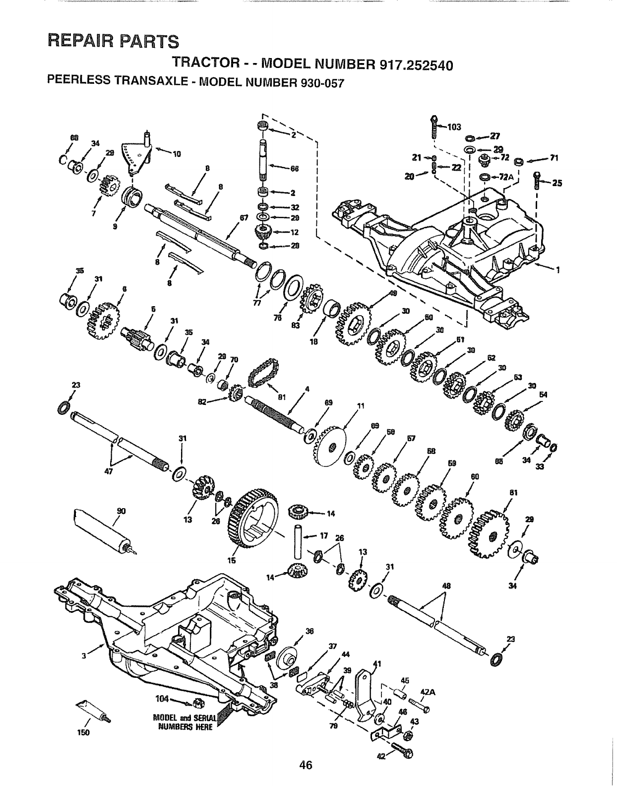
REPAIR PARTS
TRACTOR ,.- MODEL NUMBER 917.252540
PEERLESS TRANSAXLE - MODEL NUMBER 930-057
8
!8
/ /
5
23
/
13
15
L
77
18
623O
36
44
45
42A
/
&..,%
46

REPARR PARTS
TRACTOR - - MODEL NUMBER 917.252540
PEERLESS TRANSAXLE - MODEL NUMBER 930-057
REF PART REF PART
NO, NO. DESCRIPTION NO, NO. DESCRIPTION
1 772108A Transaxle Cover 45 786066
2 780086 Needle Bearing 46 786086
3 770102A Transaxle Case 47 774690
4 776260 Countershaft 48 774691
5 776219B Output Shaft & Pinion 49 778215
6 778139 Output Gear, 35 Teeth 50 778125
7 778136 Spur Gear, 15 Teeth, Steel 51 778124A
8 792136A Shift Key 52 778123A
9 784352 Shift Collar 53 778122A
10 784355 Shift Rod & Fork 54 778273
11 778229 Bevel Gear, 42 Teeth 56 778230
12 778113A Input Bevel Pinion 57 778151
13 778221 Bevel Gear, 16 Teeth 58 778126A
14 778068 Differential Pinion 59 778127A
15 778260 Ring Gear 60 778128A
17 786139 Drive Pin 61 778163
18 786102 Spacer 65 780109
20 792077 Steel Ball, 5/16" Diameter 66 776I 35
21 792078 Set Screw 3/8-16 x 3/8 67 776315A
22 792079 Spring 68 786116
23 788061 Seal Ring 69 780051
25 792073 Screw 1/4-20 x !-1/4 70 786118
26 792125 Retaining Ring, Package of 2 7t 788069
27 792035 Retaining Ring 72 792165
28 788040 Retaining Ring 72A 788091
29 780072 Washer 76 780090
30 780t08 Washer 77 788078A
31 780001 Washer
32 792001 "O" Ring 79 792144
33 788051 Square Cut Ring 81 786081
34 780105A Flanged Bushing
35 780118A Flanged Bushing 82 786082
36 790003 Brake Disk 83 786123
37 790007 Brake Pad Plate 90 788067B
38 799021 Brake Pad, Package of 2 103 792166
39 786026 Dowel Pin 104 792167
40 792076A Washer 150 510334
41 790079 Brake Lever
42 792073 _ Screw 1/4-20 x 1-1/4
42A 792085A Screw 1/4-20 x 2-1/4
43 792075 Locknut 5/16-24
44 790025 Brake Pad Holder
Spacer
Brake Lever Bracket
Axle, 11-15/16" Long
Axle, t6-1/2" Long
Spur Gear, 37 Teeth, Steel
Spur Gear, 35 Teeth
Spur Gear, 30 Teeth
Spur Gear, 25 Teeth
Spur Gear, 22 Teeth
Spur Gear, 19 Teeth, Steel
Spur Gear, 12 Teeth, Steel
Spur Gear, 15 Teeth
Spur Gear, 20 Teeth
Spur Gear, 25 Teeth
Spur Gear, 28 Teeth
Spur Gear, 31 Teeth
Washer
Input Shaft
Shifter and Brake Shaft
Disk
Washer
Spacer
Square Cut Ring
Threaded Plug 9!16-18
"O" Ring
Washer
Inverted Retaining Ring,
Package of 2
Spring
Roller Chain,
Number 41 Chain, 24 Links
Sprocket, 9 Teeth
Reverse Sprocket, 18 Teeth
Grease, Bentonite, 32 Ounce Bottle
Screw 1/4-20 x 2
Locknut 1/4-20
Gasket Eliminator, Loctite #515
Parts must be ordered from Tecumseh Products Coo
NOTE: All component dimensions given in U,,S, inches
1 inch = 254 mm
47
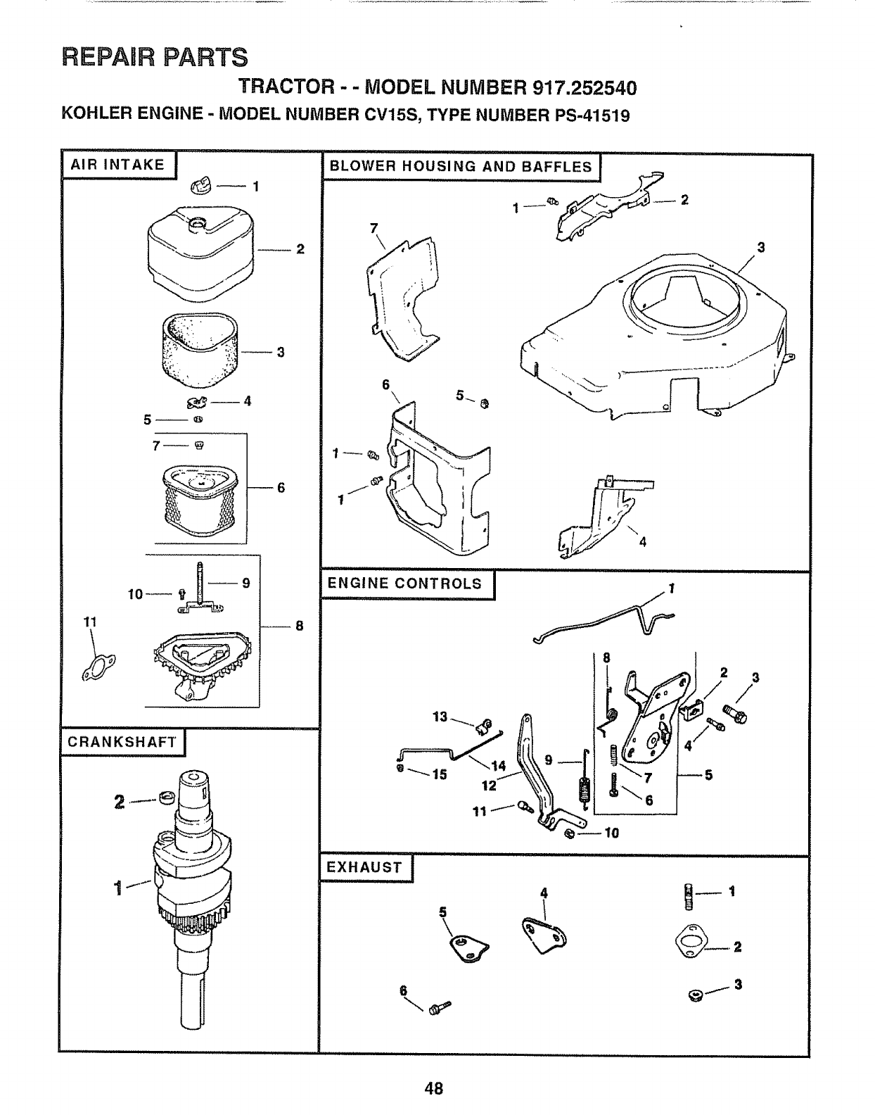
REPARRPARTS
TRACTOR -- MODEL NUMBER 917.252540
KOHLER ENGINE - MODEL NUMBER CV15S, TYPE NUMBER PS-41519
A,R,.TAKEI
3
_6
2
1! _8
..... A,F,T,I
CRANKSH
BLOWER HOUSING AND BAFFLES
7
@
,.%
ENGINE CONTROLS
i,iiiiiiii ii
2 3
/
4
6
48
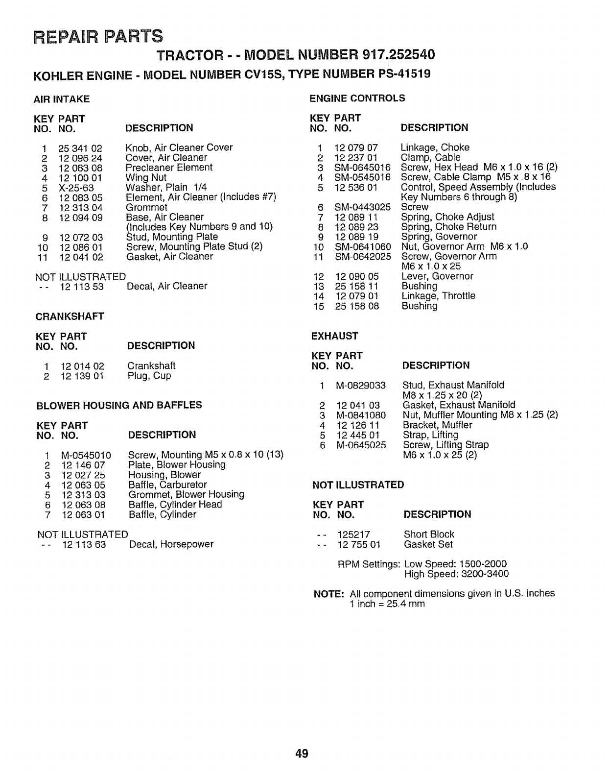
REPABR PARTS
TRACTOR - - MODEL NUMBER 917.252540
KOHLER ENGINE - MODEL NUMBER CV15S, TYPE NUMBER PS-41519
AIR INTAKE ENGINE CONTROLS
KEY PART KEY PART
NO. NO. DESCRIPTION NO. NO.
1 25 341 02
2 t2 096 24
3 12 083 08
4 12 100 01
5 X-25-63
6 12 083 05
7 12 313 04
8 12 O94 O9
Knob, Air Cleaner Cover
Cover, Air Cleaner
Precleaner Element
Wing Nut
Washer, Plain 1/4
Element, Air Cleaner (includes #7)
Grommet
Base, Air Cleaner
(Includes Key Numbers 9 and 10)
Stud, Mounting Plate
Screw, Mounting Plate Stud (2)
Gasket, Air Cleaner
9 12 072 03
10 12 086 01
11 1204102
NOT ILLUSTRATED
- - 12 1t3 53 Decal, Air Cleaner
CRANKSHAFT
DESCRIPTION
1 12 079 07
2 12 237 01
3 SM-0645016
4 SM-0545016
5 12 536 01
6 SM-0443025
7 12 089 11
8 12 089 23
9 12 089 19
10 SM-0641060
11 SM_0642025
12 12 090 05
13 25 t58 11
14 1207901
15 25 158 08
Linkage, Choke
Clamp, Cable
Screw, Hex Head M6 x 1..0x 16 (2)
Screw, Cable Clamp M5 x o8x 16
Control, Speed Assembly (Includes
Key Numbers 6 through 8)
Screw
Spring, Choke Adjust
Spring, Choke Return
Spring, Governor
Nut, Governor Arm M6 x 1.0
Screw, Governor Arm
M6 x 140x 25
Lever, Governor
Bushing
Linkage, Throttle
Bushing
KEY PART
NO. NO. DESCRIPTION
1 !2 014 02 Crankshaft
2 12 13901 Plug, Cup
BLOWER HOUSING AND BAFFLES
KEY PART
NO. NO. DESCRIPTION
1 M-0545010
2 12 146 07
3 12 O27 25
4 12 063 05
5 12 313 03
6 12 063 08
7 12 063 01
Screw, Mounting M5 x 0.8 x 10 (13)
Plate, Blower Housing
Housing, Blower
Baffle, Carburetor
Grommet, Blower Housing
Baffle, Cylinder Head
Baffle, Cylinder
NOT ILLUSTRATED
-- 12 113 63 Decal, Horsepower
EXHAUST
KEY PART
NO. NO.
1 M_0829033
2 12 041 03
3 M-0841080
4 12 126 11
5 12 445 01
6 M_0645025
DESCRIPTION
Stud, Exhaust Manifold
M8 x 1.25 x 20 (2)
Gasket, Exhaust Manifold
Nut, Muffler Mounting M8 x 1.25 (2)
Bracket, Muffler
Strap, Lifting
Screw, Lifting Strap
M6 x 1.0 x 25 (2)
NOTILLUSTRATED
KEY PART
NO. NO.
-- 125217
-- 12 755 0t
DESCRIPTION
Short Block
Gasket Set
RPM Settings: Low Speed: 1500-2000
High Speed: 3200-3400
NOTE: All component dimensions given in U.S. inches
I inch = 254 mm
49
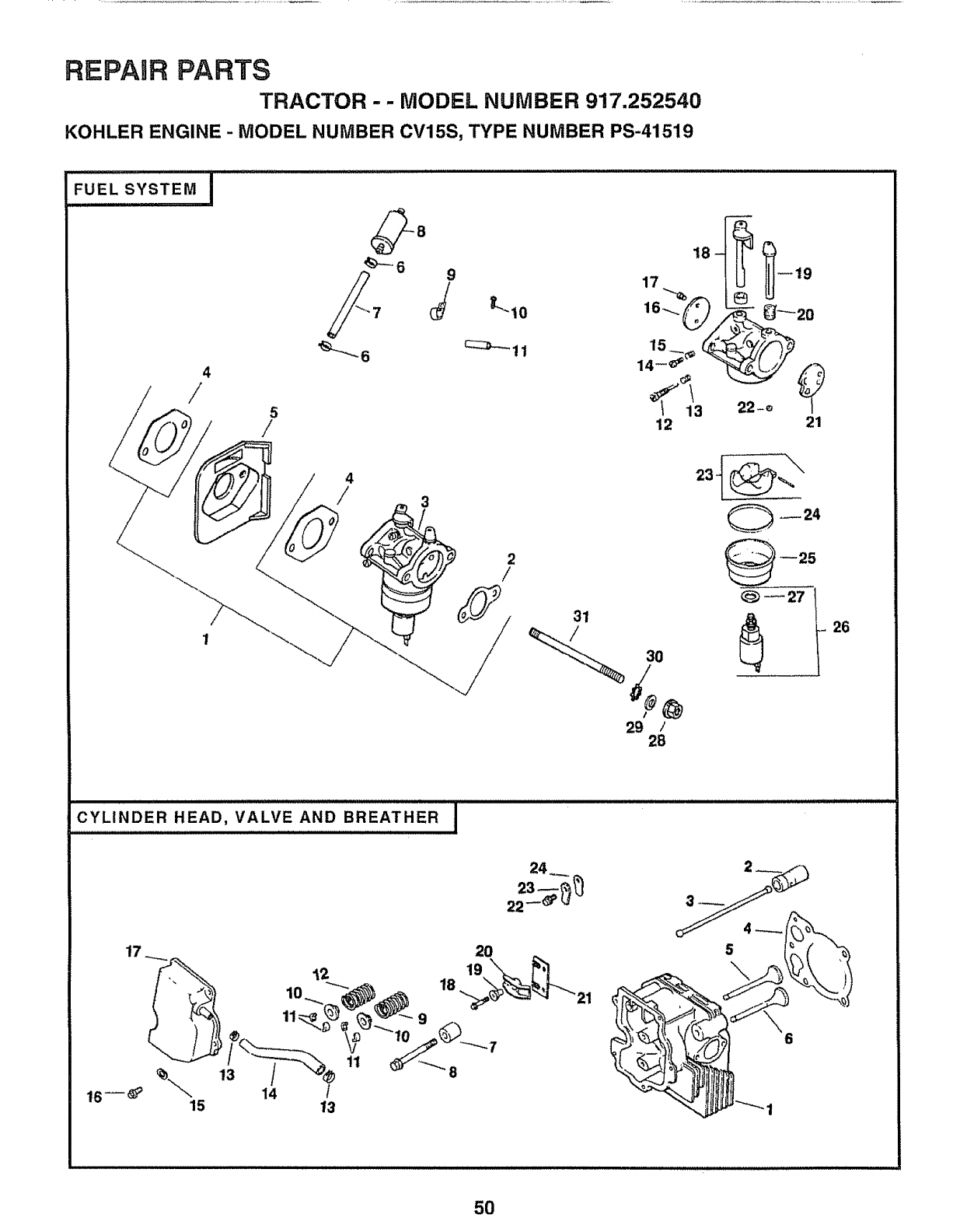
REPAIR PARTS
TRACTOR - - MODEL NUMBER 917.252540
KOHLER ENGINE- MODEL NUMBER CV15S, TYPE NUMBER PS-41519
.....F0,'SYs+EI
4
/5
/
(_8
_-6 9
4
/
18-
17..%
16-... _)
14__ _
12
__°
21
2
/
31
__o
29 /
28
--25
CYLINDER HEAD, VALVE AND BREATHER J
11
5
5O
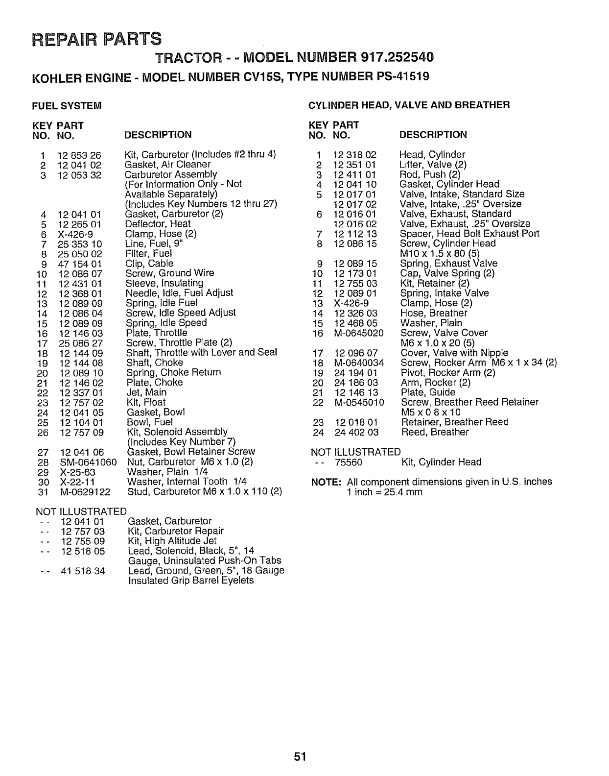
REPAIR PARTS
TRACTOR - - MODEL NUMBER 917.252540
KOHLER ENGINE -MODEL NUMBER CV15S, TYPE NUMBER PS-41519
FUEL SYSTEM CYLINDER HEAD, VALVE AND BREATHER
KEY PART KEY PART
NO. NO. DESCRIPTION NO. NO. DESCRIPTION
1 !2 853 26
2 12 041 02
3 12 053 32
4 12 041 01
5 12 265 01
6 X-426-9
7 25 353 10
8 25 05O O2
9 47154 0t
10 12 086 07
11 12 431 01
12 12 368 01
13 12 089 09
14 12 086 04
15 12 089 09
16 I2 146 O3
17 25 086 27
18 12 144 09
19 12 144 08
20 12 O89 10
21 12 146 02
22 12 337 01
23 12 757 02
24 12 041 05
25 12 104 01
26 12 757 09
Kit, Carburetor (Includes #2 thru 4) 1
Gasket, Air Cleaner 2
Carburetor Assembly 3
(For Information Only - Not 4
Available Separately) 5
(includes Key Numbers 12 thru 27)
Gasket, Carburetor (2) 6
Deflector, Heat
Clamp, Hose (2) 7
Line, Fuel, 9" 8
Filter, Fuel
Clip, Cable 9
Screw, Ground Wire 10
Sleeve, Insulating 11
Needle, idle, Fuel Adjust 12
Spring, Idle Fuel 13
Screw, Idle Speed Adjust 14
Spring, Idle Speed 15
Plate, Throttle 16
Screw, Throttle Plate (2)
Shaft, Throttle with Lever and Seal 17
Shaft, Choke 18
Spring, Choke Return 19
Plate, Choke 20
Jet, Main 21
Kit, Float 22
Gasket, Bowl
Bowl, Fuel 23
Kit, Solenoid Assembly 24
(Includes Key Number 7)
Gasket, Bowl Retainer Screw
Nut, Carburetor M6 x ln0 (2)
Washer, Plain 1/4
Washer, Internal Tooth 1/4
Stud, Carburetor M6 x 1o0x 110 (2)
27 12 041 06
28 SM-0641060
29 X-25-63
3O X-22q1
3I M-0629122
ILLUSTRATED
12 041 01 Gasket, Carburetor
12 757 03 Kit, Carburetor Repair
12 755 09 Kit, High Altitude Jet
12 518 05 Lead, Solenoid, Black, 5", 14
Gauge, Uninsulated Push*On Tabs
41 518 34 Lead, Ground, Green, 5", 18 Gauge
Insulated Grip Barrel Eyelets
NOT
w
12 3!8 02
12 351 01
I2 411 01
12 041 10
12 017 01
12 017 02
12 016 01
12 016 02
12 112 13
12 086 15
I2 089 15
12 173 01
12 755 O3
12 089 01
X426-9
12 326 03
12 468 05
M-0645020
12 O96 O7
M-0640034
24 194 01
24 186 03
12 146 13
M-0545010
12 018 01
24 402 03
Head, Cylinder
Lifter, Valve (2)
Rod, Push (2)
Gasket, Cylinder Head
Valve, Intake, Standard Size
Valve, Intake, _25" Oversize
Valve. Exhaust, Standard
Valve, Exhaust, .25" Oversize
Spacer, Head Bolt Exhaust Port
Screw, Cylinder Head
M10 x 1.5 x 80 (5)
Spring, Exhaust Valve
Cap, Valve Spring (2)
Kit, Retainer (2)
Spring, Intake Valve
Clamp, Hose (2)
Hose, Breather
Washer, Plain
Screw, Valve Cover
M6 x 1,O x 20 (5)
Cover, Valve with Nipple
Screw, Rocker Arm M6 x 1 x 34 (2)
Pivot, Rocker Arm (2)
Arm, Rocker (2)
Plate, Guide
Screw, Breather Reed Retainer
M5 x 0.8 x 10
Retainer, Breather Reed
Reed, Breather
NOT ILLUSTRATED
-- 75560 Kit, Cylinder Head
NOTE: All component dimensions given in US. inches
1 inch = 25.4 mm
5'1
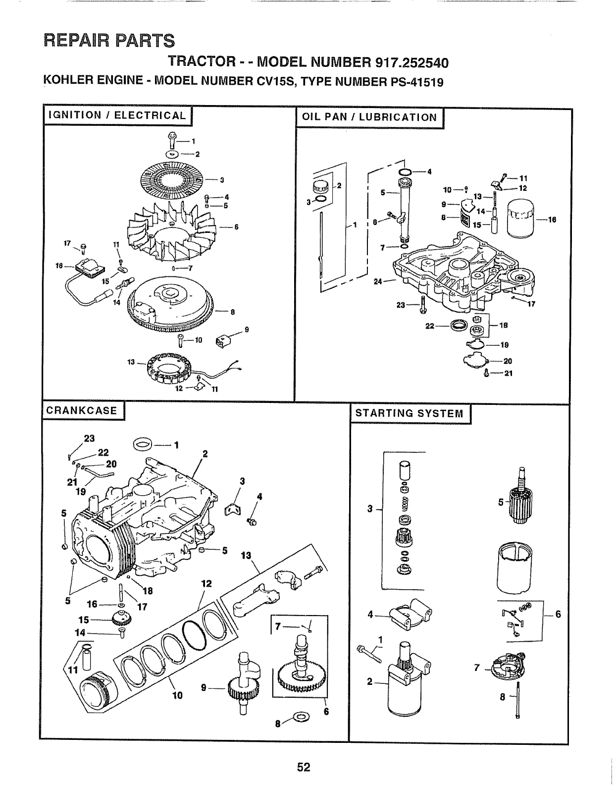
REPAURPARTS
TRACTOR - - MODEL NUMBER 917.252540
KOHLER ENGINE - MODEL NUMBER CV15S, TYPE NUMBER PS-41519
IGNITION tELECTRICAL 1
,,,u i iii ,i,ui
,
C_2
17 ...,_ il\
\_'_ __o
CRANK:CAS,E,,,,!
OIL PAN /LUBRICATION
llrH,ll i i,i iii
J
STA.T,.Q......................S_STE.I
ll,llli, ii ill ............
5_
52
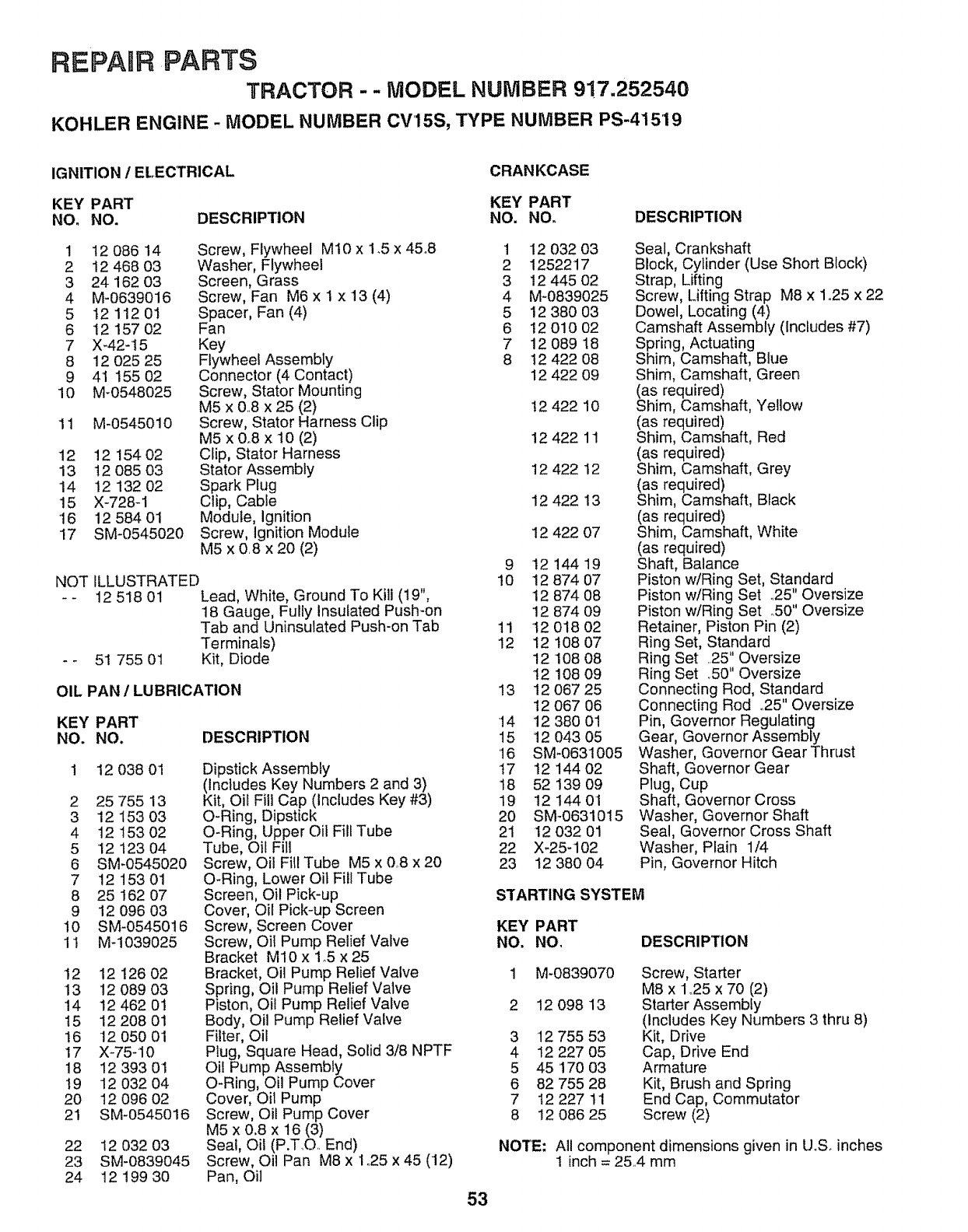
REPARR ,PARTS
TRACTOR - - MODEL NUMBER 9!7.252540
KOHLER ENGINE -MODEL NUMBER CV15S, TYPE NUMBER PS-41519
IGNITION 1ELECTRICAL CRANKCASE
KEY PART KEY PART
NO. NO. DESCRIPTION NO. NO. DESCRIPTION
1 12 086 14 Screw, Flywheel Mt0 x 1.5 x 45.8
2 12 468 03 Washer, Flywheel
3 24 162 03 Screen, Grass
4 M-0639016 Screw, Fan M6 x 1 x 13 (4)
5 12 112 01 Spacer, Fan (4)
6 1215702 Fan
7X_42-15 Key
8 12 025 25 Flywheel Assembly
9 41 155 02 Connector (4 Contact)
10 M-0548025 Screw, Stator Mounting
M5 x &8 x 25 (2)
11 M-0545010 Screw, Stator Harness Clip
M5 x 0.8 x 10 (2)
12 12 154 02 Clip, Stator Harness
13 12 085 03 Stator Assembly
14 12 132 02 Spark Plug
15 X-728-1 Clip, Cable
'16 12 584 01 Module, Ignition
17 SM-0545020 Screw, Ignition Module
M5 x 0.8 x 20 (2)
ILLUSTRATED
12 518 01 Lead, White, Ground To Kill (19",
18 Gauge, Fulty Insulated Push-on
Tab and Uninsulated Push-on Tab
Terminals)
51 755 01 Kit, Diode
NOT
OIL PAN /LUBRICATION
DESCRIPTION
KEY PART
NO. NO.
12 038 01
2 25 755 13
3 12 153 03
4 12 15302
5 12 123 04
6 SM-0545020
7 12 15301
8 25 162 07
9 12 096 03
10 SM-0545016
11 M-1039025
12 12 126 02
13 !2 089 03
14 124620'1
15 12 2O8 01
16 12 050 01
17 X-75-10
18 12 393 01
t9 12 032 04
20 12 096 02
21 SM-0545016
Dipstick Assembly
(includes Key Numbers 2 and 3)
Kit, Oil Fill Cap (Includes Key #3)
O-Ring, Dipstick
O-Ring, Upper Oil Fill Tube
Tube, Oil Fill
Screw, Oil Fill Tube M5 x 0..8x 20
O-Ring, Lower Oil Fill Tube
Screen, Oil Pick-up
Cover, Oil Pick-up Screen
Screw, Screen Cover
Screw, Oit Pump Relief Valve
Bracket M10 x 1.5 x 25
Bracket, Oil Pump Relief Valve
Spring, Oil Pump Relief Valve
Piston, Oil Pump Relief Valve
Body, Oil Pump Relief Valve
Filter, Oil
Plug, Square Head, Solid 3/8 NPTF
Oil Pump Assembly
O-Ring, Oil Pump Cover
Cover, Oil Pump
Screw, Oil Pump Cover
M5 x 0.8 x 16 (3)
Seal, Oil (P.T_O.. End)
Screw, Oil Pan M8 x 1.25 x 45 (12)
Pan, Oil
22 12 032 03
23 SM-0839045
24 12 199 30
1
2
3
4
5
6
7
8
12 032 03
1252217
12 445 02
M-0839025
12 380 03
!2 010 02
12 089 18
t2 422 08
12 422 09
!2 422 10
12 422 11
12 422 12
12 422 13
12 422 07
9 1214419
10 12 874 07
12 874 08
12 874 09
11 12 018 O2
12 12 !08 07
12108 08
12108 09
13 12 O67 25
12 067 06
14 12 380 01
15 12 043 05
16 SM-0631005
17 12 144 02
18 52 139 09
19 12144 01
20 SM-0631015
21 12 032 01
22 X-25-102
23 12 380 04
Seal, Crankshaft
Block, Cylinder (Use Short Block)
Strap, Lifting
Screw, Lifting Strap M8 x 1o25 x 22
Dowel, Locating (4)
Camshaft Assembly (Includes #7)
Spring, Actuating
Shim, Camshaft, Blue
Shim Camshaft, Green
(as required)
Shim, Camshaft, Yellow
(as required)
Shim, Camshaft, Red
(as required)
Shim, Camshaft, Grey
(as required)
Shim, Camshaft, Black
(as required)
Shim, Camshaft, White
(as required)
Shaft, Balance
Piston w/Ring Set, Standard
Piston w/Ring Set _25" Oversize
Piston w/Ring Set .50" Oversize
Retainer, Piston Pin (2)
Ring Set, Standard
Ring Set ..25" Oversize
Ring Set .50" Oversize
Connecting Rod, Standard
Connecting Rod ..25"Oversize
Pin, Governor Regulating
Gear, Governor Assembly
Washer, Governor Gear Thrust
Shaft, Governor Gear
Plug, Cup
Shaft, Governor Cross
Washer, Governor Shaft
Seal, Governor Cross Shaft
Washer, Plain 1/4
Pin, Governor Hitch
STARTING SYSTEM
KEY PART
NO. NO, DESCRIPTION
1 M-0839070 Screw, Starter
M8 x 1.25 x 70 (2)
2 12 098 13 Starter Assembly
(Includes Key Numbers 3 thru 8)
3 12 755 53 Kit, Drive
4 12 227 05 Cap, Drive End
5 45 '170 03 Armature
6 82 755 28 Kit, Brush and Spring
7 I2 227 11 End Cap, Commutator
8 12 086 25 Screw (2)
NOTE: All component dimensions given in U.S. inches
1inch = 25.4 mm
53

SERVICE OTES
54

SUGGESTED GUIDE FOR SiGHTiNG SLOPES FOR SAFE OPERATION
O'1
SIGHTING
GUIDE
ONLY RIDE UP AND DOWN HILL,
NOT ACROSS HILL
SIGHT AND HOLD THIS LEVEL WITH
SKY LINE OR TREE.
15 ° MAX.
i iiii, I,,. '!I II[I lllLllllllll[l rI I' II UI!!LIJ l
_1 A Operate your Tractor up and down the face of slopes (not !
li_ A_ qreater than 15°), never across the face. Make turns gradu-
Ii_ _ ally to prevent tipping or loss of control. Exercise extreme
lil caution when changing direction on slopes.
1_ I II I J[

OWNER'S
MANUAL
MODEL NO.
917.252540
IF YOU NEED
REPAIR SERVICE
OR PARTS:
FOR REPAIR SERVICE, CALL
THIS TOLL FREE NUMBER:
1-800-4-REPAIR
(I -800-473-7247)
FOR REPLACEMENT PARTS
INFORMATION AND
ORDERING, CALL THIS
TOLL FREE NUMBER:
1-800-FON-PART
(1-800-366-7278)
FOR CONSUMER ASSISTANCE
HOT LINE, CALL THIS
TOLL FREE NUMBER:
1-800-659-5917
®
14.5 HP
ELECTRIC START
3 in One Convertible
42" MOWER
6 SPEED TRANSAXLE
LAWN TRACTOR
Each tractor has its own model number., Each engine has
its own model number.
The model number for your tractor will be found on the
model plate located under the seat_
The model number for your engine will be found on the
blower housing of the engine.
All parts listed herein may be ordered from any Sears,
Roebuck and Co. Service Center/Department and most Re-
tail Stores°
WHEN ORDERING REPAIR PARTS, ALWAYS GIVE THE
FOLLOWING INFORMATION:
o PRODUCT- TRACTOR
° MODEL NUMBER - 917.252540
° ENGINE MODEL NO. -CV15-41519
=PART NUMBER
• PART DESCRIPTION
Your Sears merchandise has added value when you
consider Sears has service units nationwide staffed with
Sears trained technicians.., professional technicians
specifically trained to insure that we meet our pledge to
you, we service what we sell.,
147191 Rev. 2 07.19.95 KFSW Printed in U.S,A.
