Seas of Solutions McMurdo M-2 McMurdo Automatic Identification System User Manual Installation Manual
Orolia Ltd McMurdo Automatic Identification System Installation Manual
Contents
- 1. Installation Manual
- 2. Operation Manual
Installation Manual

Installation Manual
M-2 AIS Transponder System
35-060-001
This page contains no other data
Contents
1 PREFACE.................................................................................................................................. 1
2 INSTALLING THE AIS TRANSPONDER SYSTEM SAFELY........................................................ 2
3 INTRODUCTION ........................................................................................................................ 5
3.1 ABOUT THIS MANUAL.............................................................................................................. 5
4 AIS TRANSPONDER SYSTEM................................................................................................... 7
4.1 SYSTEM CONFIGURATION ....................................................................................................... 7
4.2 INSTALLATION ACCESSORIES ................................................................................................... 7
4.3 AIS BUILDING BLOCKS ............................................................................................................ 7
5 MECHANICAL MOUNTING OPTIONS AND GUIDELINES..........................................................10
5.1 LOCATION ...........................................................................................................................10
5.2 AIS TRANSPONDER UNIT .......................................................................................................10
5.2.1 Transponder main dimensions .....................................................................................10
5.3 AIS DISPLAY .......................................................................................................................13
5.3.1 AIS Display trunnion assembly.....................................................................................13
5.3.2 AIS Display flush mount assembly ...............................................................................14
5.4 ANTENNA UNITS ...................................................................................................................15
5.4.1 Antenna mounting position ..........................................................................................15
5.4.2 VHF antenna..............................................................................................................15
5.4.3 GNSS antenna ...........................................................................................................15
5.4.4 Weld on plate mounting of the GNSS antenna..............................................................16
5.4.5 Cable Preparation.......................................................................................................17
6 ELECTRICAL CONNECTIONS ..................................................................................................19
6.1 GROUND CONNECTION..........................................................................................................19
6.2 SIGNAL CABLE CONNECTIONS FOR AIS TRANSPONDER...............................................................19
6.3 VHF AND GNSS (GPS) ANTENNA CABLE CONNECTIONS ............................................................20
6.3.1 VHF antenna..............................................................................................................21
6.3.2 GNSS (GPS) antenna .................................................................................................21
6.4 CONNECTION TERMINALS.......................................................................................................22
6.4.1 Fuse values ................................................................................................................22
6.4.2 Signal line termination .................................................................................................22
6.4.3 Method of connecting screens at the transponder .........................................................23
6.4.4 Test and program connections.....................................................................................24
6.4.5 Power supply..............................................................................................................24
6.4.6 DISP port – Display.....................................................................................................25
6.4.7 SEN 1, 2, 3, 4 ports - Sensors......................................................................................25
6.4.8 SEN Ports necessary sentences:.................................................................................26
6.4.9 Main and AUX high speed input/output ports ................................................................26
6.4.10 MAIN port ...................................................................................................................27
6.4.11 AUX/Pilot port .............................................................................................................27
6.4.12 Pilot Plug connection...................................................................................................27
6.4.13 Long Range Port.........................................................................................................27
6.4.14 RTCM port, Differential GNSS correction input/output port.............................................27
6.4.15 Alarm relay .................................................................................................................27
6.5 COMPLETION OF INSTALLATION...............................................................................................28
7 SPECIFICATION.......................................................................................................................29
7.1 TECHNICAL INFORMATION......................................................................................................30
7.1.1 RS-422 interfaces .......................................................................................................30
7.1.2 Termination ................................................................................................................30
7.1.3 Output drive capability.................................................................................................30
7.1.4 Input loading...............................................................................................................30
7.1.5 Isolation .....................................................................................................................30
7.2 RTCM BINARY MESSAGES .....................................................................................................30
7.3 NMEA SENTENCES USED ......................................................................................................30
7.4 MESSAGE STRUCTURES ........................................................................................................32
7.4.1 ABK - AIS addressed and binary broadcast acknowledgement ......................................32
7.4.2 ABM – AIS addressed binary and safety related message.............................................32
7.4.3 ACA – AIS channel assignment message.....................................................................32
7.4.4 ACK – Acknowledge alarm..........................................................................................32
7.4.5 ACS - AIS channel management information source.....................................................33
7.4.6 AIR – AIS interrogation request ...................................................................................33
7.4.7 ALR – Alarm condition and status ................................................................................33
7.4.8 BBM - AIS broadcast binary message ..........................................................................33
7.4.9 DTM – Datum reference..............................................................................................34
7.4.10 GBS – GNS satellite fault detection..............................................................................34
7.4.11 GGA – Global positioning system (GPS) fix data...........................................................34
7.4.12 GLL – geographic position...........................................................................................35
7.4.13 GNS – GNSS fix data..................................................................................................35
7.4.14 HDT – heading true.....................................................................................................35
7.4.15 LR1 - AIS long-range reply 1 .......................................................................................35
7.4.16 LR2 - AIS long-range reply 2 .......................................................................................36
7.4.17 LR3 - AIS long-range reply 3 .......................................................................................36
7.4.18 LRF - AIS long-range function......................................................................................36
7.4.19 LRI - AIS long-range interrogation................................................................................37
7.4.20 RMC – recommended minimum specific GNSS data.....................................................37
7.4.21 ROT – rate of turn.......................................................................................................37
7.4.22 TXT – text transmission...............................................................................................37
7.4.23 VBW – Dual ground/water speed .................................................................................38
7.4.24 VDM – VHF data link message....................................................................................38
7.4.25 VDO - AIS VHF Data-link own-vessel report .................................................................38
7.4.26 VSD – AIS voyage static data......................................................................................39
7.4.27 VTG – course over ground and ground speed...............................................................39
7.4.28 VSD – AIS voyage static data......................................................................................39
7.5 GENERAL FAULTS & ERROR MESSAGES ....................................................................................39
8 SERIAL INTERFACE COMMUNICATIONS PROTOCOLS..........................................................41
8.1 SENSOR DATA INTERFACE .....................................................................................................41
8.2 MAIN AND AUX PORT RECEPTION AND TRANSMISSION OF AIS DATA .............................................41
9 WARRANTY REGISTRATION & ACCEPTANCE RECORD........................................................43
10 PRE-INSTALLATION INSPECTION RECORD........................................................................45
11 GLOSSARY..........................................................................................................................49
12 COMMISSIONING GUIDE .....................................................................................................51

AIS Installation Manual Issue 1 1
1 Preface
Applicability of this manual
This manual describes the installation of equipment to hardware build standard 02.02.
In accordance with McMurdo's policy of continual development and product improvement, hardware may
be upgraded from time to time and future versions may therefore not correspond exactly with this manual.
When necessary, upgrades will be accompanied by updates or addenda to this manual.
IMPORTANT: Please take time to read this manual carefully and to understand its contents fully, so that
you can install your AIS system correctly.
Once installed please read the Operation Manual fully to make sure you understand how to use your new
AIS.
Disclaimer
Information contained in this manual is supplied in good faith, but is liable to change without notice.
McMurdo Limited disclaims any liability for consequences arising from omissions or inaccuracies in the
manuals and documentation provided with this product.
2004 McMurdo Ltd.

2 Issue 1 AIS Installation Manual
2 Installing the AIS Transponder System Safely
Installation
WARNING: Do not connect the AIS transponder system to a mains (line) AC electrical
supply, as an electric shock or fire hazard could result.
CAUTION: Do not connect the Transponder to a DC supply exceeding 32 V or reverse the
supply polarity. Damage to the transceiver may result.
CAUTION: Do not bypass the built in fuse
CAUTION: The Transponder system is designed for operation in the temperature range
-15 °C to +55 °C. Do not install (or use) the transponder system in environments which exceed
this range.
CAUTION: The AIS Transponder is not water-resistant. Consequently, the Transponder must
be installed in a dry place and must be protected from direct contact with water.
WARNING: Do not install the Transponder system in a position where;
a) the controls of your vessel may be obstructed.
b) it may obstruct your normal movement around your vessel.
c) it may cause bodily injury.
d) it cannot be easily accessed in an emergency.
Use
WARNING: Certain parts of the Transponder chassis, notably the rear panel, can become
hot, particularly if the ambient temperature is high. Avoid touching these areas when the
Transponder is operating.
WARNING: Do not remove the cover of the Transponder before the power is switched off.
Do not touch the antenna connections when the Transponder is operating and do not touch the
antenna whip (mast) or connecting cable when the Transponder is in operation, for RF
exposure and electrical safety reasons. Refer to Radio Frequency Exposure Warning.
WARNING: Unauthorised opening of the Transponder system will invalidate the warranty.
Maintenance
CAUTION: Avoid using chemical solvents to clean the Transponder system as some
solvents can damage the case material.
NOTE: Apart from the fuse located beside the connectors, the Transponder system contains no
user serviceable parts. Contact your Service Agent for repair if replacing the fuse fails to make
the equipment servicable.

AIS Installation Manual Issue 1 3
Radio Frequency Exposure Warning
To meet the current requirements for Radio Frequency Exposure it is necessary to install the
antenna mast correctly and operate the equipment according to the instructions.
The assumptions used in this assessment are: full transmit power is used, a good antenna is
used (assumed to be a unity gain (0 dB) wideband omni-directional type).
Where no suitable structure exists to achieve a 3 metre vertical separation then the antenna
base must be mounted at least 1 metre above the head of any person within range and all
persons must stay outside the 3-metre safety radius.
Failure to adhere to these limits could expose persons within the 3 metre radius to RF radiation
in excess of the MPE / SAR limits.
WARNING: The antenna mast must be mounted at a minimum distance (vertical separation)
of 3 metres from the head of any person standing on deck to meet international safety directives
on Maximum Permissible Exposure (MPE) / Specific Absorption Rate (SAR).
WARNING: Do not transmit when persons are closer than 3 metres to the antenna. If any
person (e.g. the operator) must be closer, then a grounded RF shield should be interposed
between that person and the antenna.
Rules of Operation
Licensing
IMPORTANT: In most countries the operation of the AIS Transponder is a part of the radio
regulations and therefore the ship must possess a current VHF radio telephone licence which
lists the AIS system, and the equipment must be registered (Call Sign and MMSI number).
Please contact the relevant authority in your country for more information.
Refer to the AIS Transponder Operation Manual for the full operating procedure.
Good Practice
The installer is expected to be familiar with IMO SN/Circ.227 Guidelines for the Installation of a
Shipborne Automatic Identification System, and to comply with these recommendations. The
document contains detailed information which supplements the instructions in this manual.
Compass Safe Distances
Display 0.7 m for 1° deviation; 1.2 m for 0.3° deviation
Transponder: 1.3 m for 1° deviation; 2.1 m for 0.3° deviation

4 Issue 1 AIS Installation Manual
This page contains no other data

AIS Installation Manual Issue 1 5
3 Introduction
It is recommended that the vessel should be surveyed prior to commencing any installation
work to determine the suitability of the existing on-board sensors. Section 8 of this Manual
contains a ‘Pre-Installation Inspection’ form to assist this process.
Installation of the AIS Transponder has been designed to be as easy as possible and requires
few tools. However as the AIS equipment forms a vital part of the ship’s navigational equipment
the installation must be performed with great care and with attention to detail.
The AIS is considered part of the ship’s radio station and is surveyed together with the radio
installation. Surveys on Convention ships should be carried out in accordance with the rules laid
down in IMO Res. A 746(18) Survey Guidelines under the harmonised system of survey and
certification and Protocol of 1988 relating to the International Convention for the Safety of Life at
Sea 1974
For the AIS installation, it is likely that the following drawings will be required for the survey:
• Antenna layout for the VHF and the GNSS antenna installation
• AIS Arrangement drawing
• Block diagram showing the interconnection to other units
To assist in the preparation of this information, a Pre-installation Inspection Record is included
in this manual at section 10. Completion of this Record will provide much of the required
information.
It is also necessary to complete an installation report, which shall be kept on board.
3.1 About this manual
This manual provides step-by-step guidance through the installation of the AIS Transponder
system. Please read the manual carefully and make sure to follow the instructions.
In this manual only the installation of the AIS stand-alone configuration will be described. If the
AIS unit is to be connected to other display devices, refer to the manual for that display.
However the setup must always be performed with the supplied Display unit.. Other display
units will be additional to the IMO required installation.
The procedures required for installation can be summarised:
1. Obtain a copy of the AIS Pre-installation Inspection form; check that it is filled in with all the
data necessary for the installation. If the form has not been filled in, it is advisable to do it at
this stage, as this is a good way to make sure that all information is available for the
installation.
2. The available AIS Transponder system building blocks are listed in section 4.3. Before
starting the installation ensure that everything needed for the installation is to hand.
3. Locate the places to install the different units. The templates and the drilling instructions are
provided in this manual.
4. Connect the units and the sensors as shown in this manual.
5. DO NOT POWER UP THE SYSTEM AT THIS STAGE. It is most important to read the
Operation Manual, which contains the detailed commissioning information, before power is
applied.
6. Once the operating procedures are understood, the system may be powered up and the
permanent parameters may be set. A guide listing the steps in this procedure is provided as
Section 12 of this manual.
The Warranty Registration & Acceptance Record, Section 9 at the rear of this manual, must be
completed and signed when the system has been commissioned and accepted.

6 Issue 1 AIS Installation Manual
This page contains no other data

AIS Installation Manual Issue 1 7
4 AIS Transponder System
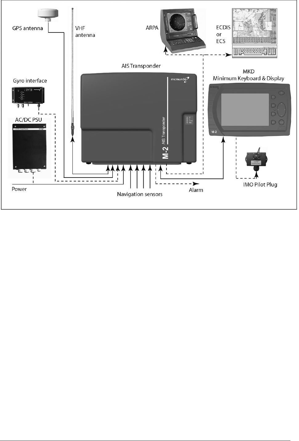
4.1 System Configuration
The M-2 may be installed as stand-alone AIS equipment or integrated with Electronic Charting
Systems (ECS) or Integrated Bridge Systems (IBS).
Stand-Alone System The AIS transponder with Display unit is interfaced to the vessel's
primary navigation sensors. The Display is used as both the AIS display unit and AIS control
unit.
Electronic Chart System (ECS) with AIS In this arrangement the stand-alone AIS installation
and ECS display have been integrated. The Display is used mainly to input own ship's
information with the ECS having the ability to display AIS target information. This arrangement
greatly enhances the presentation of information by displaying AIS targets in an environment
normally used for navigation of the vessel.
Integrated Bridge System has the ability to display AIS target information directly on an
Automatic Radar Plotting Aid (ARPA ) or Electronic Chart Display and Information System
(ECDIS). By combining these technologies the navigator is provided with the optimum
navigational information, directly on the vessel’s primary navigation display. Where approved for
this purpose the ARPA or ECDIS equipment maybe used to directly control the function of the
AIS transponder.
4.2 Installation accessories
An optional AIS installation cable kit contains all the basic installation materials and cables that
are typically needed to ready a vessel for installation of the AIS equipment.
Other accessories include a VHF antenna and a range of antenna bracket options, an AC/DC
power supply unit, a Gyro Interface Unit (Stepper/Synchro gyro input - RS422 output) and a
remote IMO Pilot Plug kit. (The Pilot Plug may be supplied with the system, depending on the
configuration ordered.)
4.3 AIS building blocks
M-2 Class A AIS system, comprising: Part 35-001-001A
- AIS transponder unit
- Display unit
- GNSS antenna
- Connector kit
- Operator and installation manuals
M-2 Class A AIS system, comprising: Part 35-001-002A
- AIS transponder unit
- Display unit
- GNSS antenna
- Connector kit
- Operator and installation manuals
- Pilot plug kit (-002 version)
8 Issue 1 AIS Installation Manual
Packaging
M-2 Master Carton
Contains:-
1 x M-2 Transponder
2 x PL259 Plug for VHF Antenna
2 x TNC Plug for GNSS Antenna
4 x M6 x 40 mm Machine Screws for Bulkhead Mounting
1 x Display interconnect cable 5 m
1 x Set of screw terminal connectors (bagged)
1 x Installation Manual
1 x M-2 Display unit
1 x Trunion Mounting Bracket
1 x Flush Mounting Frame
4 x No.10 x 25 mm Self-Tapping Screws for mounting Trunnion Bracket
1 x Seal for Flush Mounting Frame
1 x Operation Manual
1 x GPS Antenna
1 x Stub mounting pole
2 x ‘U’ Bolts
1 x Back Plate
1 x Pilot Plug kit (-002 version) if part of system

AIS Installation Manual Issue 1 9
Optional Extras:
Part Description
89-020-001 AIS VHF antenna, 1.2 mtr 0 db Gain
903-01 Antenna bracket -stand off mast
903-02 Antenna bracket -stand off mast / Bulkhead
903-04 Antenna deck mount fitting
89-081-001 Pilot Plug kit to AIS Transponder, 25 m cable
89-081-002 Pilot Plug kit to Display, 5 m cable with D plug
89-028 Gyro Interface Unit - Stepper / Synchro input - RS422 output
89-029 AIS Power supply unit AC+DC input - 24 V DC output
89-038 AIS Installation cable Kit (standard);
20 mtrs x 2 mm 2-Core Flex Power Cable
30 mtrs x RG214 VHF Coax Antenna Cable
30 mtrs x RG58 GPS Coax Antenna Cable
60 mtrs x 0.5 mm 4-Twisted Pair + Drain Signal Cable
200 x Cable Ties
20 x Cable Markers
2 x Self Amalgamating Tape
2 x PL259 connector
2 x TNC connector
10 Issue 1 AIS Installation Manual
5 Mechanical mounting options and guidelines
5.1 Location
The transponder unit is classed as protected equipment and thus should be located inside in a
dry environment. Normally the transponder is located in the Radio Room. The transponder
compass safe distance is 2.1 m.
The recommended location should provide:
A dry environment
Access to connections (eg antennas, power, sensors)
Minimal shock and vibration
An ambient temperature between -15 °C and +55 °C
A site clear of exhausts and vents
Sufficient space to allow maintenance
The transponder does not require external illumination during operation. Naturally, some form of
illumination should be provided while installing or maintaining the transponder.
The Display should be available to the mariner at the position from which the ship is normally
operated. The Display compass safe distance is 0.7 m. The Display does not require external
illumination during operation, as it has an internal backlight; the use of illuminated keys ensures
that all controls are visible.
The Pilot Plug should be installed on the bridge near the pilot’s operating position. It is
recommended that a suitable mains outlet (3-pin 120 V AC) should be available at this location.
Special siting considerations apply to antennas. These principles are outlined in section 5.4; for
detailed advice, see the IMO Guidelines.
5.2 AIS Transponder unit
The transponder mounting plate is attached by four M6 screws. Keyhole slots in the plate allow
two screws to be inserted in the mounting surface, then the plate to be mounted on the screws
and to be self-supporting while the remaining screws are inserted and all screws are tightened.
The transponder chassis is then attached to the plate using four screws, as shown overleaf. The
transponder may be mounted at any angle.
It is recommended to leave at least 300 mm free space around the terminals to allow for
connection cables.
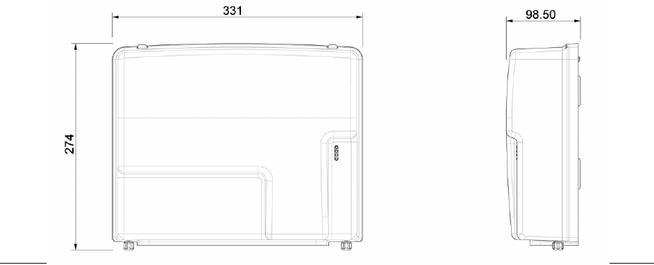
5.2.1 Transponder main dimensions
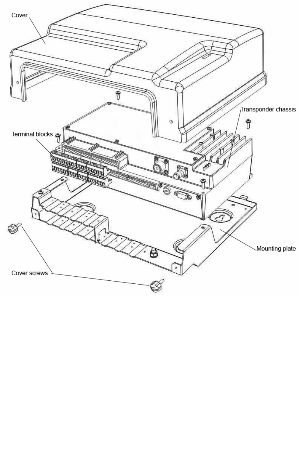
AIS Installation Manual Issue 1 11
Exploded view of M-2 transceiver showing cover, detachable terminal blocks and mounting plate

12 Issue 1 AIS Installation Manual
Transponder mounting plate drilling diagram and recommended clearances ( mm)
AIS Installation Manual Issue 1 13
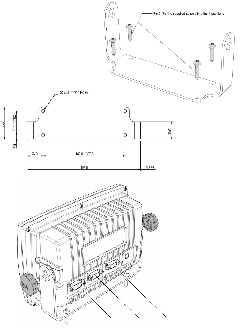
5.3 AIS Display
5.3.1 AIS Display trunnion assembly
The Display can be either trunnion mounted or flush mounted.
Hole size to fit #10 screw: 3.5mm
Drilling drawing
(mm)
Select hole size to suit method of
fixing mountings – clear or
tapped holes.
Mounted dimensions:
Height: 150 mm
Width: 270 mm
Depth: 120 mm
(over connectors)
Connectors: Display port Pilot Plug Test port
14 Issue 1 AIS Installation Manual
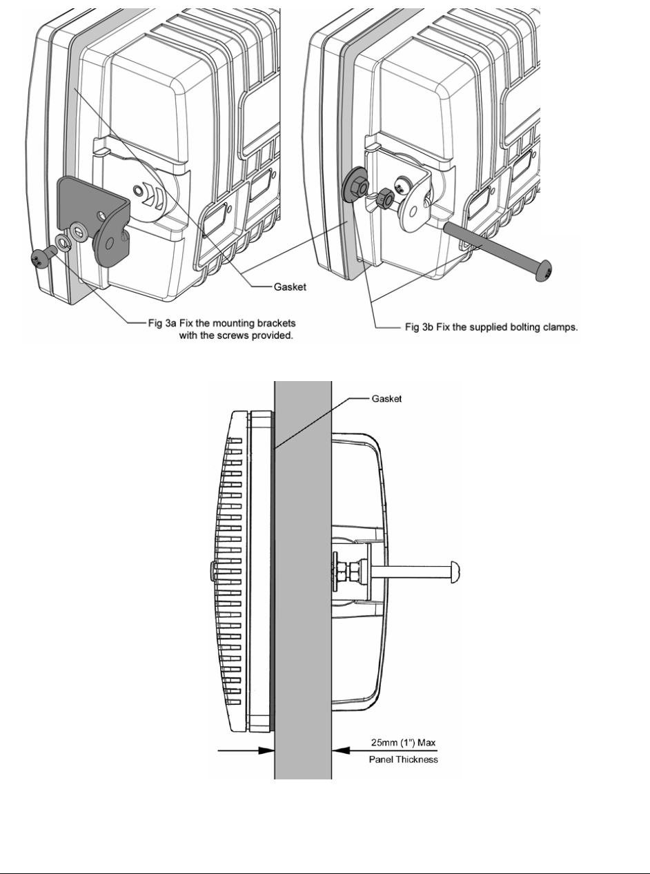
5.3.2 AIS Display flush mount assembly
NOTE: The Pilot Plug is intended to be connected to the Display, although an alternative
connection is available on the transponder. The cabling arrangements should take this into
consideration when flush mounting the Display.
A cutting template is supplied with the flush mounting kit. This template carries full fitting
instructions.
FRONT
AIS Installation Manual Issue 1 15
5.4 Antenna units
The AIS Transponder has to be connected to two antennas: a VHF antenna and a GNSS
antenna. The GNSS (GPS) antenna is supplied as standard.
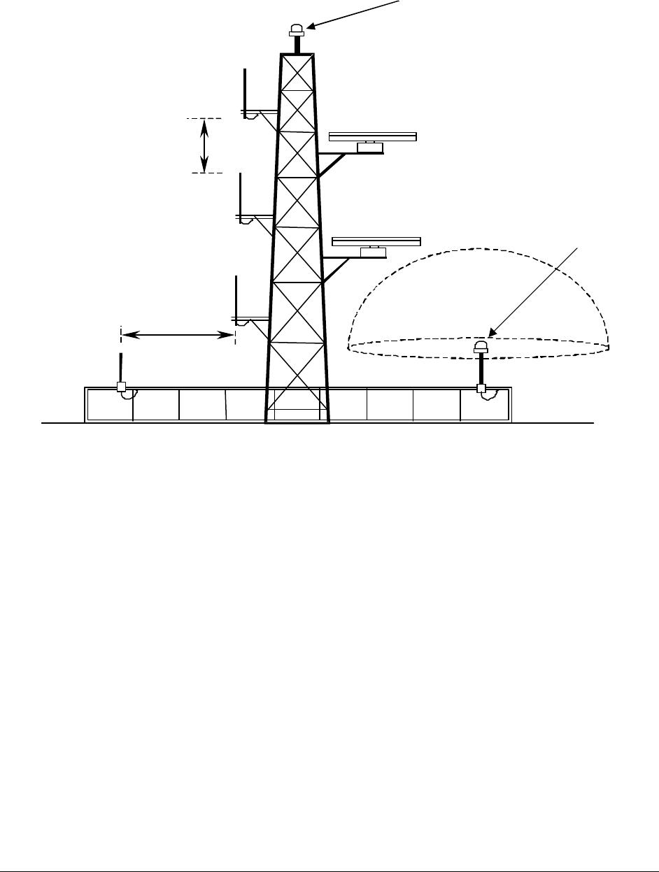
5.4.1 Antenna mounting position
In accordance with IMO guidelines, antennas should be mounted in positions which, as far as
possible, minimise interaction between them. The sketch summarises the recommendations:
5.4.2 VHF antenna
The VHF antenna is an important part of the receiver and transmitter system; the reception
range is heavily dependent on the antenna installation. The VHF antenna must be installed as
high as possible and free of shadow effects from the ship superstructure; effective installation
will maximise the range of the system. The antenna must also be mounted so as to achieve the
safety standards detailed in Section 2.
WARNING: The antenna must have sufficient bandwidth to suit the AIS system, as otherwise
the high VSWR produced may cause the transponder to shut down. It is recommended to use
an omni-directional vertical polarised VHF antenna with unity gain (0 dB), and a bandwidth
sufficient to maintain VSWR <1.5 over the frequency range 156 – 163 MHz. A suitable antenna
is available from McMurdo as an option, part number 89-020-001.
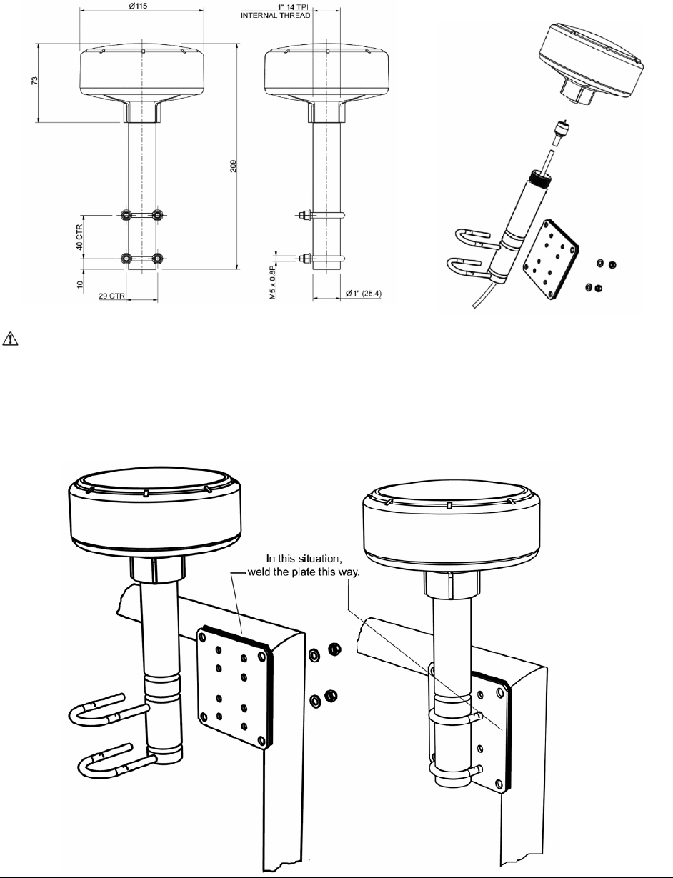
5.4.3 GNSS antenna
The Transponder package contains a GNSS antenna and a mounting bracket. The mounting
bracket is designed for welding to the ship’s superstructure.
Installation of the GNSS antenna is critical for the performance of the GNSS, which is used for
timing of the transmitted time slots and for the supply of navigational information should the
main navigational GNSS fail. We strongly recommend that the supplied antenna is used.
1. The GNSS antenna must be mounted in an elevated position and free of shadow effect
from the ship’s superstructure
Vertical
separation
2m
GNSS antenna
alternative
position
180°
Horizontal
separation
10 m
Vertical
Separation
2 m
360°
GNSS antenna
preferred
position
16 Issue 1 AIS Installation Manual
2. The GNSS antenna must have a free view through 360 degrees with a vertical angle of 5
to 90 degrees above the horizon.
3. As the received GNSS signal is very sensitive to noise and interference generated by
other onboard transmitters, ensure that the GNSS antenna is placed as far away as
possible from Radar, Inmarsat and Iridium transmitters. Ensure the GNSS antenna is free
from direct view of the Radar and the Inmarsat beam. It is also important that the MF/HF
and other VHF transmitter antennas are kept as far away as possible from the GNSS
antenna. It is good practice never to install a GNSS antenna within a radius of 5 meters
from these antennas.
WARNING: Screw the rod into the GNSS antenna by turning the rod. Do not turn the GNSS
antenna as this will twist the cable and damage the connection.
5.4.4 Weld on plate mounting of the GNSS antenna
AIS Installation Manual Issue 1 17
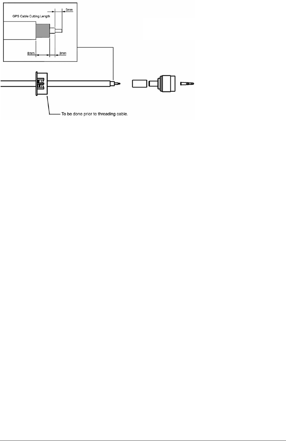
5.4.5 Cable Preparation
Ensure grommet is fitted before connector

18 Issue 1 AIS Installation Manual
This page contains no other data

AIS Installation Manual Issue 1 19
6 Electrical connections
This installation guide takes into account the IMO “Guidelines for installation of Shipborne
Automatic Identification System”. However both the IMO publication and these instructions must
be taken as guidance only; individual circumstances must take precedence.
This guide is concerned only with the installation of the AIS transponder unit and does not cover
the installation of any peripheral equipment connected to the transponder. For proper
installation and connection of peripheral equipment to the transponder refer to the installation
manuals for these products.
Connection Must connect Optional
24.0 VDC power supply* Yes
GNSS antenna Yes
VHF antenna Yes
Display system Yes
Position (external GNSS) Yes
Heading (vessel gyro) Yes
Pilot plug See Note 1 See Note 1
Alarm Relay Yes
ECDIS (Main port) Yes
ARPA (Main port) Yes
Long range function Yes
RTCM, differential GNSS info. Yes
Rate of turn Yes
Speed and Course Yes
*WARNING: Ensure supply is compatible with voltage and current requirements.
Note 1: depends on IMO recommendations and local legislation.
6.1 Ground Connection
The earth stud on the transponder backplate must be connected to ship’s ground. The
recommended connector wire is 4 mm2, green/yellow colour.
6.2 Signal cable connections for AIS Transponder
As shown in the table above, the AIS Transponder must be or may be connected to different
types of peripheral units; these can be divided in three groups:
• Coax connection to the antennas
• signal cable connection to the sensors (GNSS, Gyro, Log)
• signal cable connections to the five-input/output ports (Main, AUX/Pilot, long-range,
RTCM, Display)
Connecting the three types of interfaces is described in detail in the following sections.
The signal connections are all connected via a serial RS422 type interface; data rates are
normally 4800 or 38400 baud.
In some cases, particularly in retrofit installations, it may not be possible to connect the AIS
directly to the required sensor, because some sensors do not provide the IEC 61162-2 (NMEA)
sentences required by the AIS unit. In such cases a protocol converter is required between the
sensor and the AIS unit. Converters are available from different manufacturers, either as direct
protocol converters or frequently as repeater instruments for the sensor. A Gyro Interface Unit,
P/N 89-028, is available from McMurdo as an optional extra.
20 Issue 1 AIS Installation Manual
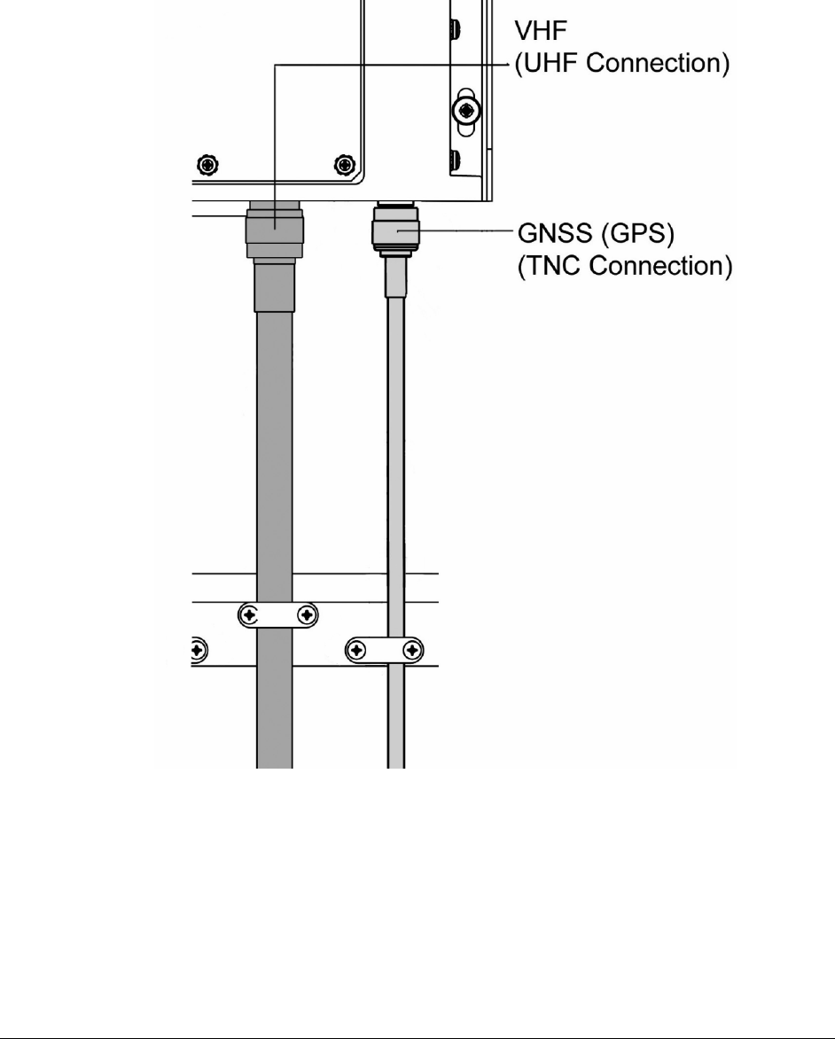
6.3 VHF and GNSS (GPS) antenna cable connections
The VHF and the GNSS antenna cables are connected directly to the transponder through a
UHF and a TNC plug respectively.
The coax cable plugs must be attached directly to the cables; the outer insulation must not be
connected in the cable cleat but in the coax plug as illustrated below.
AIS Installation Manual Issue 1 21
6.3.1 VHF antenna
To make sure that the transmitted and received VHF signal is not interfering with Radar signals,
other VHF transmission or power lines it is important that the connection between the VHF
antenna and the transponder is of a high quality double shielded coax cable. It is recommended
to use a RG214 cable and PL259 connector.
If the cable has to be longer than 40 metres, it is recommended to use a cable with lower loss; a
40 metre RG214 coax cable has a signal attenuation of 3 dB at 150 MHz, thus the signal
strength is reduced to half its value due to cable attenuation.
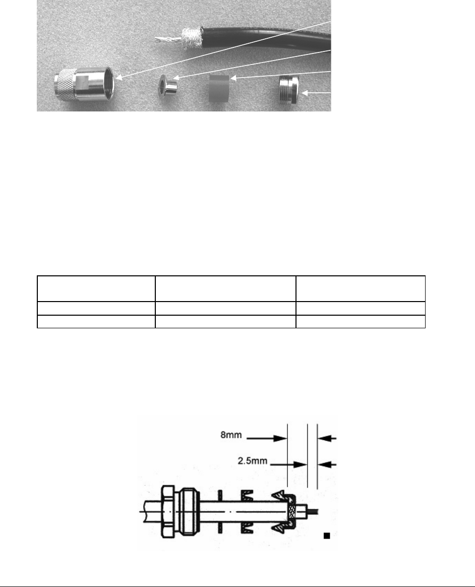
Detailed instructions for fitting the connector are provided with the installation kit. The illustration
shows the preparation of the cable and the components of the connector.
6.3.2 GNSS (GPS) antenna
The GNSS operates in the ultra high frequency band (1.575 GHz). The signal attenuation in
cables is therefore substantial and has to be taken into account when the coax cable between
the antenna and the AIS unit is chosen. To compensate for signal attenuation the supplied
GPS antenna includes a pre-amplifier with a gain of 30 dB.
The cable attenuation should not be greater than 30 dB for optimum results, because the aim is
to have a total signal loss of less than 0 dB. The table shows the attenuation and the
recommended maximum length of two types of coax cable.
Cable description Attenuation / 100 metres
@ 1.5 GHz Recommended
maximum cable length
RG 58 70 dB 40 metres
RG 214 37 dB 80 metres
Connectors used must be TNC throughout.
Detailed instructions for fitting the connector are provided with the installation kit. The illustration
shows the preparation of the cable.
Connector
body
“Top hat”
Plastic sleeve
Gland nut
22 Issue 1 AIS Installation Manual
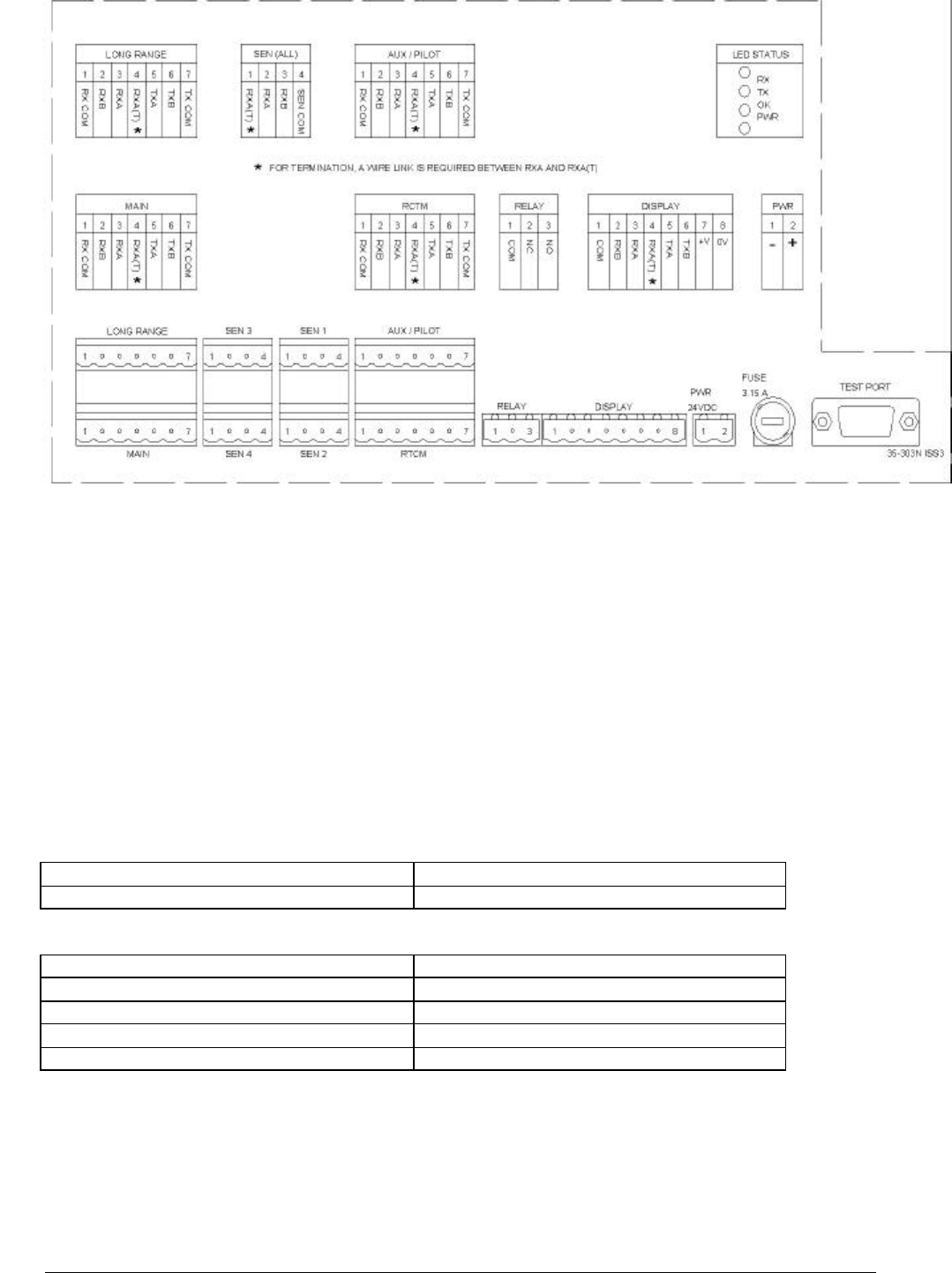
6.4 Connection terminals
The AIS Transponder has detachable terminal blocks for connection of cables. Dedicated
connections are provided for power sources, sensors, the Display and other interfaces.
Refer to the wiring diagram, attached as an appendix, for details of connections to the terminal
blocks.
6.4.1 Fuse values
The main system fuse (3.15 Amp) is located beside the connectors on the transponder chassis.
Fuse description Fuse value Part No.
Main system fuse 3.15 Amp 99-084
6.4.2 Signal line termination
RS422 signal lines may need termination by resistors, depending on the length of connecting
cable and the rate of data transmission. Suitable resistors are incorporated in the transponder
listeners and can be switched in by wire links in the corresponding screw terminal blocks – see
subsequent tables and section 6.4.4 for details. The talkers in the transponder have inbuilt
termination resistors.
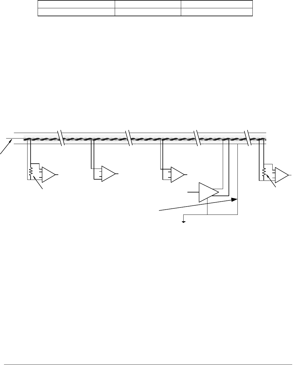
Whether termination at the transponder is required depends on many factors, including how the
other units are connected and whether any of these other units provides termination for the
signal line. The following sketch shows the principle:
Note: For clarity, the sketch shows the devices connected to the twisted pair by spurs; in practice, the twisted pair is
looped through each device in turn.
There is only one talker per twisted pair; there can be several listeners. The intention is that
terminations must be provided by the devices at the ends of the line, regardless of whether they
are listeners or the talker, and that no other device should provide a termination.
A terminal is provided for the common connection at each port on the transponder; note that this
is NOT a ground connection.
It is good practice to use screened cables in all ship cable installations. Take care to connect
the cable screen to ship’s ground at one end only of the cable, as connecting at both ends may
cause ground loops and interference to the signals. The correct method of connecting the cable
screen to ground is at the talker only, as shown in the diagram above.
ListenerListener
Talker
Termination resistor
at end of line
Screen connected to ground
at talker ONLY
Twisted pair, with common and screen
Common Listener
Termination resistor
at end of line
Listener
AIS Installation Manual Issue 1 23
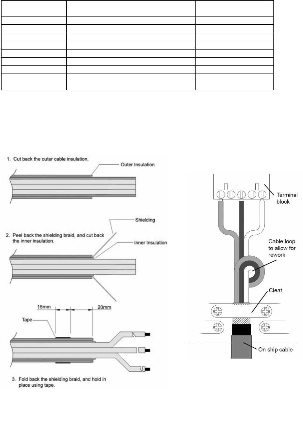
In the transponder unit the screen from some cable entries should be connected to ground at
the transponder, as shown in the table. The technique of connecting the screen is illustrated
below.
Function Lines terminated by resistor Connect screen
at transponder
Display Display (VDU) port YES
LONG RANGE Long Range port PREFERRED
AUX / PILOT Auxiliary or Pilot port PREFERRED
MAIN Main port PREFERRED
RTCM RTCM port for differential correction PREFERRED
SEN 1 Sensor 1 port NO
SEN 2 Sensor 2 port NO
SEN 3 Sensor 3 port NO
SEN 4 Sensor 4 port NO
PREFERRED means that the screen may be connected either at the remote device or at the
transponder; if no other considerations apply, connection at the transponder is recommended.
6.4.3 Method of connecting screens at the transponder
If the screen is not to be connected at the transponder, secure the cleat over the outer cable
insulation.
24 Issue 1 AIS Installation Manual
6.4.4 Test and program connections
The connectors are 5mm pitch female screw terminal conectors. Manufacturer’s numbers are
given for the Hitaltech models, but any equivalent may be used.
Connectors used:
8 way 1 off CIF08001
7 way 4 off CIF07001
4 way 4 off CIF04001
3 way 1 off CIF03001
2 way RED 1 off CIF02001OR
6.4.5 Power supply
Connect to the ship’s 24 V DC emergency power source, which ideally should be an
uninterrupted power supply (UPS), through a 2-pole switched fused supply to allow isolation for
servicing. The power requirements are 24 V DC +30% -10%, 2.5 A minimum.
Standby power requirement 15 W; 0.6 Amp at 24 V DC
Peak power requirement 50 W; 2.0 Amp at 24 V DC
Required conductor area as a function of cable length
Power cable length Required conductor area
0 – 10 metres 0.75 mm2
10 – 20 metres 1.5 mm2
20 – 30 metres 2.5 mm2
30 – 40 metres 3.0 mm2
Isolation between the power supply connections and any other connection to the transponder is
1 kV minimum.
The DC power source should comply with IMO guidelines for the class of vessel concerned.
National authorities and classification societies may have their own power supply requirements;
these should also be considered.
AIS Installation Manual Issue 1 25
Power Supply Unit (optional)
An AC/DC + DC emergency backup power supply, P/N 89-029, is available as an option. Follow
the installation instructions supplied with the equipment.
6.4.6 DISP port – Display
The DISP port connects the Display unit with the Transponder. The display connection cable is
supplied ready for use, and needs only to be plugged into the appropriate ports on the
transponder and the Display.
For installations where the Display cable needs to be extended, the connections are given
below.
Display cable:
Four twisted pairs, screened, PVC sheathed. For lengths to 200 meters, use 0.22 mm2
(7/32); Belden 8104 or equivalent.
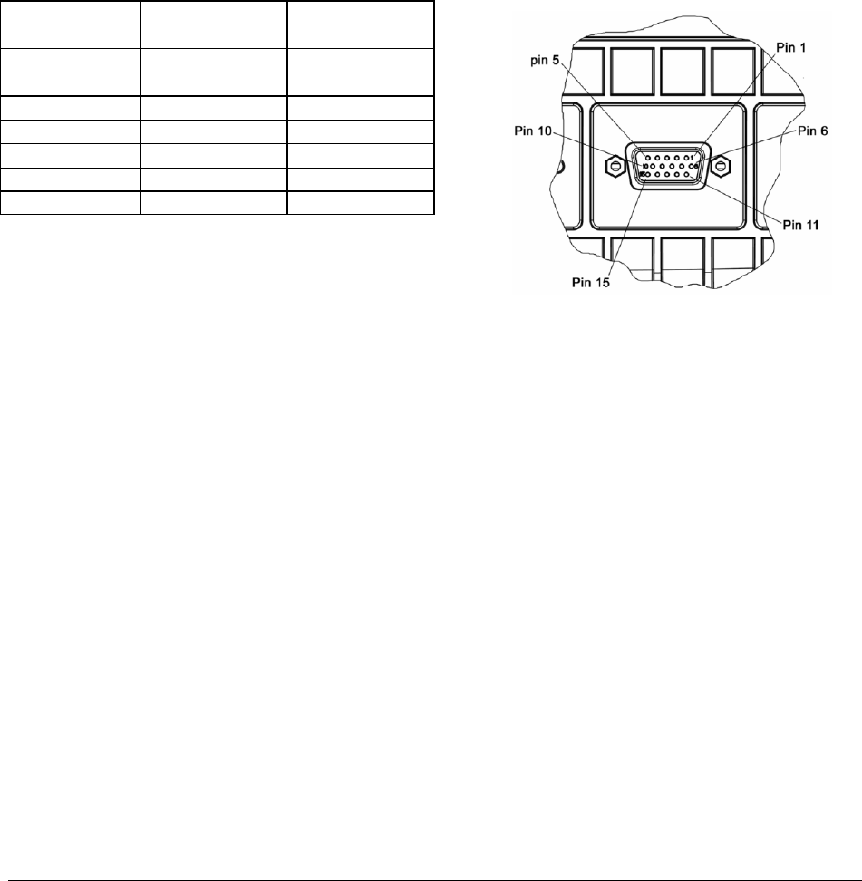
The connection between the transponder connector block and the Display unit is given below,
Connection is to the 15-pin socket on the Display.
Function Terminal Display pin
Common 1 2
Rx A 2 6
Rx B 3 1
Tx A 5 12
Tx B 6 13
Termination 4 (link to 3) 8
+ Power out 7 3
- Power out 8 4
The twisted pairs are assigned as (Rx A/B), (Tx A/B),
(common pair) and (power pair)
6.4.7 SEN 1, 2, 3, 4 ports - Sensors
Sensor input ports can be configured to receive serial data from the Gyro (or Gyro Converter),
the external GNSS used for navigation and from the LOG. Each of the four sensor (SEN1,
SEN2, SEN3 and SEN4) ports can be used to receive information from one of these sensors.
Alternatively, all sensor information can be received at any one of the sensor ports provided that
the information is first multiplexed.
The sensor ports require configuration before use; this is outlined in the Commissioning Guide,
section 12, and described in detail in the Operation Manual.
The AIS must be connected to:
• The GNSS unit used for navigation
• The gyrocompass providing heading information
If available the following information can be connected to the AIS:
• Rate-Of-Turn (ROT)
• Speed over ground from bottom-referenced log
Sensor wire connection
The twisted pair shall be assigned as RxA and RxB

26 Issue 1 AIS Installation Manual
Recommended cable for connection of Sensors:
Single twisted pair, shielded, PVC sheathed.
(Note: The recommended sensor cable, as supplied in the optional Installation Kit 89-038,
has four twisted pairs. Only one pair should be used.)
For lengths to 200 meters, use 0.22 mm2 (7/32); Belden 8102 or equivalent (2 pairs)
6.4.8 SEN Ports necessary sentences:
The basic requirements are:
IEC 61162-2 transmission standard
ITU-T V.11 electrical properties
Data bits 8, Stop bits 1, Parity none
Speed 4800 or 38400 baud (transponder speed is configurable)
All required as well as optional sentences are listed in the table; ensure that the connected
sensor transmits at least the required sentences (as given by IEC 61162-1):
IEC 61162-1 sentence format Data Preferred Optional
Reference datum DTM
Positioning system:
Time of position
Latitude/longitude
Position accuracy
GNS, GLL GGA, RMC
Speed over ground (SOG) VBW VTG, RMC
Course over ground (COG) RMC VTG, OSD
RAIM indicator GBS
Heading HDT
Rate of turn (ROT) ROT
6.4.9 Main and AUX high speed input/output ports
The Transponder has two high-speed communication ports. The ports are identical, the same
information is input and output on these ports. All information received and transmitted on the
VHF link will be reflected as correct IEC 61162 sentences. All error messages will also be
transmitted.
The Main port will primarily be used to connect external equipment such as ECDIS and ARPA
or another navigation information display system.
The AUX port is normally connected to the display unit, where it is looped through to drive the
Pilot Plug connector on the display unit. If a Pilot Plug is not required, the AUX port may be
disconnected from the display (at the transponder end) and may then be used as an additional
Presentation Interface (PI) port.

AIS Installation Manual Issue 1 27
6.4.10 MAIN port
Three twisted pairs, shielded, PVC sheathed.
For lengths to 200 meters, use 0.22 mm2 (7/32); Belden 8104 or equivalent
Main port wire connection
The twisted pairs shall be assigned as (RxA/RxB), (TxA/TxB) and (RxCom/TxCom).
6.4.11 AUX/Pilot port
Three twisted pairs, shielded, PVC sheathed.
For lengths to 200 meters, use 0.22 mm2 (7/32); Belden 8104 or equivalent
6.4.12 Pilot Plug connection
The Pilot Plug is designed to be connected to the Display. The Plug supplied with the AIS
system has the connector fitted, and needs only to be fixed and plugged in.
6.4.13 Long Range Port
The AIS Long-Range Function requires a compatible long-range communication system e.g.
Inmarsat-C. If this is available, a connection to the Inmarsat-C system can be made. It is
required that the Inmarsat-C input/output port can be interfaced using IEC 61162-2 and
understand the long-range sentences as required by IEC 61993.
Recommended cable for connection of Long Range port:
Three twisted pairs, shielded, PVC sheathed.
For lengths to 200 meters, use 0.22 mm2 (7/32); Belden 8104 or equivalent
The twisted pairs shall be assigned as (RxA/RxB), (TxA/TxB) and (RxCom/TxCom)
6.4.14 RTCM port, Differential GNSS correction input/output port
The RTCM-port is the input port for differential correction. The AIS Transponder can receive
differential correction in two ways:
• The RTCM port can be connected to a DGNSS unit. The DGNSS unit will then provide
differential correction to the AIS Transponder through the RTCM port.
• Through message 17 transmitted from a base station. The RTCM port will then work as
an output port, which can supply differential correction in RTCM format to other units.
Recommended cable for connection of RTCM-port:
Three twisted pairs, shielded, PVC sheathed.
For lengths to 200 meters, use 0.22 mm2 (7/32); Belden 8104 or equivalent
RTCM port wire connection
The twisted pairs shall be assigned as (RxA/RxB), (TxA/TxB) and (RxCom/TxCom)
6.4.15 Alarm relay
The AIS requires that an alarm output (relay) be connected to an audible alarm device or to the
ship’s alarm system, if available.
If any failure or malfunction is detected that will significantly reduce integrity or stop operation of
the AIS, an alarm is initiated. In this case:
• An alarm message is displayed on the display unit
• The alarm relay is activated
• The transponder health status LED turns off

28 Issue 1 AIS Installation Manual
• An appropriate alarm message is output via the presentation interface (Main and AUX-
ports) and repeated every 30 seconds.
The AIS transponder provides a relay connection which can be selected as normally closed or
normally open contacts.
Recommended cable for connection of alarm relay:
One twisted pair, shielded, PVC sheathed. The required cable dimension is dependent on
the current necessary to activate the alarm indicator.
Built in alarm relay ratings:
Absolute maximum ratings
Maximum switching current in contacts 0.25 Amp
Maximum carry current 1.20 Amp
Maximum switching voltage 175 V (dc or ac peak)
Test Port
The test port is intended to allow easy field reprogramming of the transponder and should not
be used in normal operation.
6.5 Completion of Installation
The foregoing provides the information necessary to perform the installation. Other useful
information is contained in the sections following.
The Pre-Installation Inspection Record (Section 8) should have been completed before
installation commenced.
It is most important that the installed system is not switched on at this stage. The
inspection procedures given in the Operation Manual must be completed before power is
applied.
The Warranty and Acceptance Record can only be completed after the system is configured, as
detailed in the Operation Manual.
Transponder Screw terminal board
N/C
Com
N/O

AIS Installation Manual Issue 1 29
7 Specification
General Data:
Power
consumption: 50 W peak
15 W average
Power supply: 24 V DC –10% +30%
AIS1 (CH87B) 161.975 MHz
AIS2 (CH88B) 162.025 MHz
Default
frequencies: DSC (CH70) 156.525 MHz
Operating
temperature: -15 °C to +55 °C
Storage
temperature: -20 °C to +70 °C
Environmental: IEC 60945 Protected Environment
(Antennas: Exposed Environment)
Transponder
size/weight 331 x 274 x 100 mm, 4 kg
VDU size/weight 220 x 150 x 72 mm, 1 kg
GPS size/weight ∅ 115 mm x 76 mm, 0.25 kg
Compass safe
distance Display: 0.7 m for 1° deviation
1.2 m for 0.3° deviation
Transponder: 1.3 m for 1° deviation
2.1 m for 0.3° deviation
GNSS receiver: Used for TDMA timing. Optionally used
for navigational information.
GNSS antenna: Patch antenna with built-in 30 dB pre-
amplifier
DSC Transmitter:
Power output: 12.5 W or 2.0 W
Frequency range: 156.025 – 162.025 MHz
Antenna
impedance: 50 ohms
TDMA Receivers:
Sensitivity: (PER) < 20% at –107 dBm (25 kHz)
Frequency range: 156.025 – 162.025 MHz
Channel spacing: 12.5 or 25 kHz
Modulation: GMSK
Data rate: 9600 bits/s
Frequency stability:
< ± 1 ppm
DSC Receiver:
Sensitivity: BER <10-4 at 107 dBm
Frequency range: 155.3 – 162.5 MHz
Channel spacing 25 kHz
Modulation 1300 Hz/2100 Hz - FSK
Frequency stability < ± 1 ppm
Serial inputs/outputs:
SENS1/2/3/4 IEC61162-1/2 (input only)
LONG RANGE,
MAIN,
AUX/PILOT, RTCM
IEC61162-1/2 (input & output)
Display RS422 non-isolated

30 Issue 1 AIS Installation Manual
7.1 Technical Information
7.1.1 RS-422 interfaces
The Transponder has eight RS-422 interfaces:
• 4 sensor data input ports SEN1, SEN2, SEN3 and SEN4
• 2 Bi-directional input/output ports MAIN and AUX/Pilot
• 1 Bi-directional input/output port RTCM
• 1 Bi-directional input/output port Long Range
All communication interfaces are compatible with IEC61162-1 (2000) and IEC61162-2 (1998)
standards.
7.1.2 Termination
Termination resistors are required at each end of the RS-422 connection, to match the
impedance of the line to minimise reflections. The figures quoted assume that the line is
correctly terminated, and allow for that extra loading.
7.1.3 Output drive capability
Each talker output has a capability of driving a minimum of 12 listeners on a terminated cable.
7.1.4 Input loading
Each receiver presents a load of approximately 12 kohm to the line. Line termination resistors
are 100 ohms.
7.1.5 Isolation
The interface isolation is 1 kV minimum throughout.
7.2 RTCM binary messages
The RTCM port on the transponder accepts incoming messages from a differential beacon
receiver in RTCM binary format and outputs messages in RTCM binary format. Differential
correction data received on the VHF data link (in message 17) is also output to the RTCM port
in RTCM binary format.
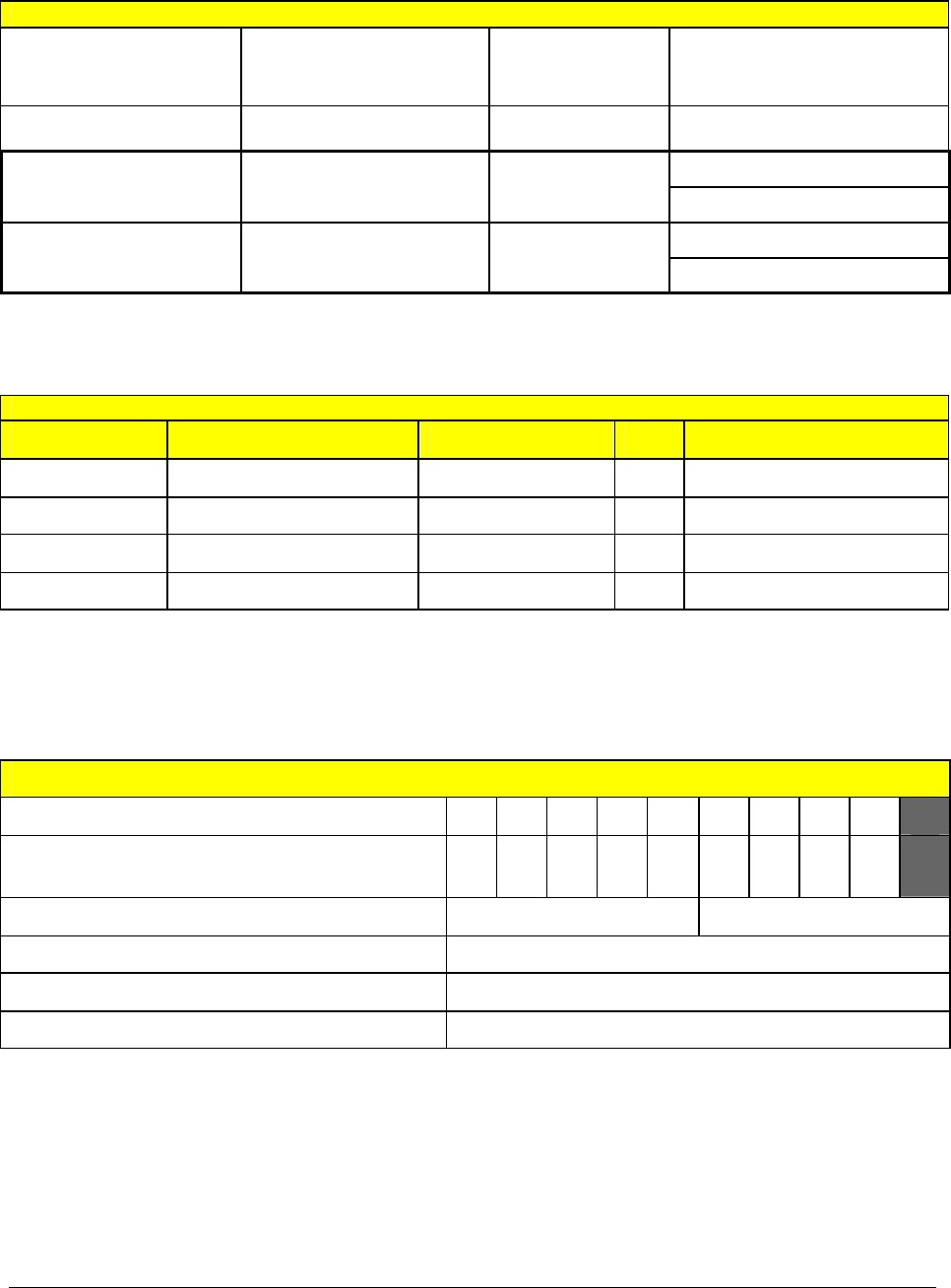
7.3 NMEA sentences used
The ports on the M-2 transponder accept and output different combinations of NMEA sentences
as follows:
Port Input sentences Output sentences
Main, Display and Aux
(“Presentation ports”) ACA, ABM, BBM, ACK, AIR,
AIQ, LRI, LRF ABK, ACA, ACS, ALR, LRI, lRF,
LR1, LR2, LR3, SSD, TXT, VDO,
VDM, VSD
Long Range LRI, LRF LRI, LRF, LR1, LR2, LR3
S1, S2, S3 and S4
(“Sensor ports”) DTM, GBS, GGA, GLL, GNS,
HDT, RMC, ROT, VBW, VTG None

AIS Installation Manual Issue 1 31
Decoded Sentences
The sentence types listed in the table below are decoded by the Transponder.
Formatter Source
Primary function Optional function Comment
ABK AIS VDL Ack
ABM AIS Addressed binary
message
BBM Broadcast binary
message
AIR AIS Interrogation
ACA AIS Channel assignment
ROT Sensor Rate of turn
HDT Sensor Heading Heading
VBW Sensor SOG
GNS GNSS Pos + time of pos
GLL GNSS Pos + time of pos
RMC GNSS COG Pos + time of pos, SOG
GBS GNSS RAIM indication RAIM
VTG GNSS COG, SOG
GGA GPS Pos + time of pos
VSD Display Voyage data
SSD Display Static data
LRF LR Long range
interrogation
LRI LR Long range
interrogation
TXT
ALR
ACK Display Alarm ack
Position Sensor Priority List
Priority (Highest first) Sources
External Differential GNSS GNS, GLL, RMC, GGA
Internal Differential GNSS (msg17) GNS, GLL, RMC, GGA
Internal Differential GNSS (RTCM ) GNS, GLL, RMC, GGA
External GNSS GNS, GLL, RMC, GGA
Internal GNSS GNS, GLL, RMC, GGA
Manual input
None available
Notes:
RAIM indication requires a valid GBS message from the sensor currently in use.
32 Issue 1 AIS Installation Manual
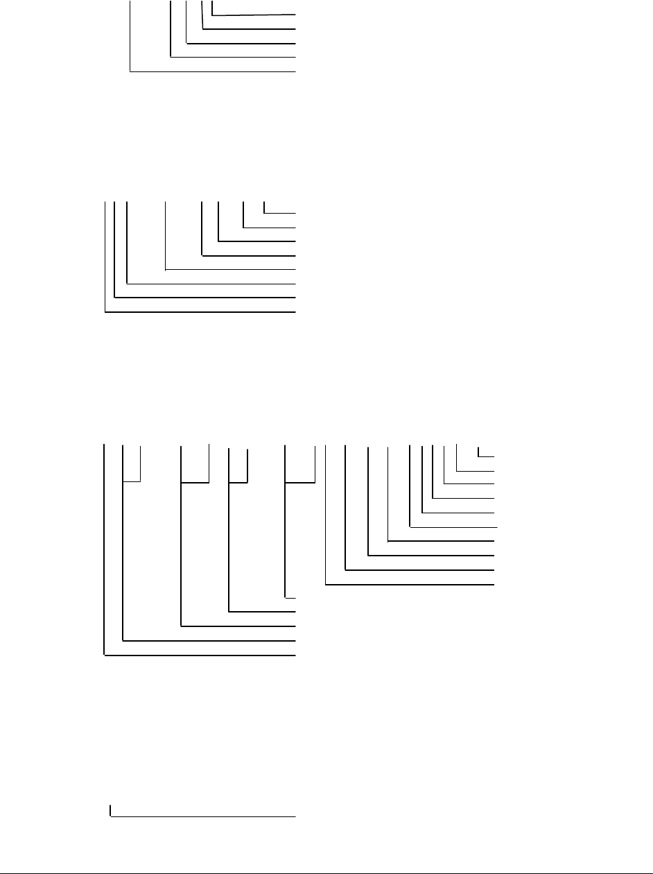
7.4 Message structures
Message structures are shown in the format used in IEC 61162-1
7.4.1 ABK - AIS addressed and binary broadcast acknowledgement
The ABK sentence is output by the transponder on the presentation ports in response to the
receipt of an ABM, AIR or BBM sentence. Its purpose is to inform the requesting device about
the success or failure of its request.
$--ABK,xxxxxxxxx,x,x.x,x,x*hh<CR><LF>
Type of acknowledgement
Message sequence number
M.1371 Message ID
AIS channel of reception
MMSI of the addressed AIS unit
7.4.2 ABM – AIS addressed binary and safety related message
This sentence is used to transmit M.1371 messages 6 (binary addressed) or 12 (addressed
safety related) via the AIS system by encapsulating the M.1371 message within one or more
AIS sentences.
$--ABM,x,x,x,xxxxxxxxx,x,xx,s—s,x*hh<CR><LF>
number of fill-bits
encapsulated data
M.1371 Message ID (6 or 12)
AIS channel
MMSI of the destination AIS unit
sequential message identifier
sentence number
total number of sentences
When the transponder receives an ABM sentence from an external device, it will return an ABK
sentence to indicate the success or failure of the transmission attempt.
7.4.3 ACA – AIS channel assignment message
$--ACA,x,llll.ll,a,yyyyy.yy,a,llll.ll,a,yyyyy.yy,a,x,xxxx,x,xxxx,x,x,x,a,x,hhmmss.ss*hh<CR><LF>
time of “in use” change
in-use Flag
information source
power level control
Tx/Rx mode control
channel B bandwidth
channel B
channel A bandwidth
channel A
transition zone size
region southwest corner longitude, E/W
region southwest corner latitude, N/S
region northeast corner longitude, E/W
region northeast corner latitude, N/S
sequence number
The ACA sentence is used both to send channel management information to the transponder
and to obtain channel management information from it.
7.4.4 ACK – Acknowledge alarm
This sentence is used to acknowledge an alarm condition.
$--ACK,xxx*hh<CR><LF>
alarm ID

AIS Installation Manual Issue 1 33
7.4.5 ACS - AIS channel management information source
This sentence is used in conjunction with the ACA sentence. It identifies the originator of the
information contained in the ACA sentence and the date and time when the transponder
received that information.
$--ACS,x,xxxxxxxxx,hhmmss.ss,xx,xx,xxxx*hh<CR><LF>
day, month, year
UTC of receipt of information
MMSI of originator
sequence number
7.4.6 AIR – AIS interrogation request
The interrogation request sentence allows an external to request certain M.1371 messages
from other remote devices via the AIS system.
$--AIR,xxxxxxxxx,x.x,x,x.x,x,xxxxxxxxx,x.x,x*hh<CR><LF>
message sub-section
number of messages requested from station-2
MMSI of interrogated station-2
message sub-section
number of second message requested from station-1
message sub-section
M.1371 message requested from station-1
MMSI of interrogated station
When the transponder receives an AIR sentence it sends M.1371 interrogation messages (type
15) to the addressed station(s) and returns an ABK sentence to the requesting device indicating
that the transmission is complete.
7.4.7 ALR – Alarm condition and status
This sentence is sent by the transponder to all presentation ports order to report an alarm
condition on a device. It identifies the source of the alarm, whether it has been acknowledged or
not and the time at which the condition changed.
$--ALR,hhmmss.ss,xxx,A,A,c--c*hh<CR><LF>
descriptive text
acknowledge state
alarm condition
alarm source
time of condition change
This sentence is sent by the transponder whenever a new alarm is raised or its condition
changes state. It is also sent periodically even when there are no active alarms In order to
provide a positive indication of the current status of each alarm.
7.4.8 BBM - AIS broadcast binary message
The BBM sentence allows an external device to instruct the transponder to broadcast a block of
binary data in an M.1371 binary broadcast message (type 8) or a safety related broadcast
message (type 14).
!--BBM,x,x,x,x,x.x,s—s,x*hh<CR><LF>
number of fill-bits
encapsulated data
M.1371 message ID
AIS channel for broadcast of the radio message
sequential message identifier
sentence number
total number of sentences needed to transfer message
When the transponder receives one or more BBM sentences from an external device, is de-
encapsulates the encoded data and re-assembles an M.1371 message of type 8 or 14 and then

34 Issue 1 AIS Installation Manual
transmits it over the VDL (if possible). It then sends an ABK sentence back to the requesting
device to indicate whether the transmission of the message succeeded or failed.
7.4.9 DTM – Datum reference
Local geodetic datum and datum offsets from a reference datum.
$--DTM,ccc,a,x.x,a,x.x,a,x.x,ccc*hh<CR><LF>
Reference datum
Altitude offset, m
Lon offset, min, E/W
Lat offset, min, N/S
Local datum subdivision code
Local datum
Note that the only datum supported by AIS is WGS84. The DTM sentence must be sent to the
transponder at a frequency of more than once every 30 seconds otherwise any positional
information sentences (eg GLL, GNS. RMC and GGA) will be ignored.
7.4.10 GBS – GNS satellite fault detection
This message is used to support receiver autonomous integrity monitoring (RAIM).
$--GBS,hhmmss.ss,x.x,x.x,x.x,xx,x.x,x.x,x.x,*hh<CR><LF>
Standard deviation of bias estimate
Estimate of bias on most likely failed satellite
Probability of missed detection for most likely failed satellite
ID number of most likely failed satellite
Expected error in altitude
Expected error in longitude
Expected error in attitude
UTC time of GGA or GNS fix associated with this sentence
7.4.11 GGA – Global positioning system (GPS) fix data
Time, position and fix-related data for a GPS receiver.
$--GGA,hhmmss.ss,IIII.II,a,yyyyy.yy,a,x,xx,x.x,x.x,M,x.x,M,x.x,xxxx*hh<CR><LF>
Differential reference
station ID
Age of differential GPS
data
Units of geoidal separation,
m
Geoidal separation
Units of antenna altitude, m
Antenna altitude
above/below mean sea
level (geoid)
Horizontal dilution of
precision
Number of satellites in use
GPS quality indicator
Longitude E/W
Latitude N/S
UTC of position

AIS Installation Manual Issue 1 35
7.4.12 GLL – geographic position
This sentence is a primary source of position information for the transponder when connected to
a functional GNSS system. In the absence of GNS sentences, longitude and latitude information
may also be obtained from GNS, GGA or RMC sentences.
$--GLL,llll.ll,a,yyyyy.yy,a,hhmmss.ss,A,a*hh<CR><LF>
mode indicator (‘A’, ‘D’, ‘E’, ‘M’ -> used; ‘N’ -> invalid)
status (‘A’ -> use mode flag; ‘V’ -> use position as default)
UTC of position
longitude, E/W
latitude, N/S
Note that DTM sentences must be received by the transponder at least once every 30 seconds
in order for the GLL sentence to be accepted.
7.4.13 GNS – GNSS fix data
The transponder may receive this sentence from other sensors and uses the information in its
own calculations of the ship’s current position.
$--GNS,hhmmss.ss,llll.ll,a,yyyyy.yy,a,c—c,xx,x.x,x.x,x.x,x.x,x.x*hh<CR><LF>
Diff ref erence station ID (ignored)
age of diff data (ignored)
geoidal separation (ignored)
antenna altitude (ignored)
HDOP (ignored)
number of satellites in use (ignored)
mode indicator (‘A’, D’, ‘E’, ‘M’ - used; ‘N’ - default value)
longitude, E/W
latitude, N/S
UTC of position
7.4.14 HDT – heading true
This sentence provides the actual vessel heading and may be sent by any system or device that
calculates true headings.
$--HDT,x.x,T*hh<CR><LF>
heading, degrees true
7.4.15 LR1 - AIS long-range reply 1
The LR1 sentence identifies the destination for the reply and contains the information items
requested by the function identification character in the LRF sentence that requested the
information.
$--LR1,x,xxxxxxxxx,xxxxxxxxx,c—c,c—c,xxxxxxxxx*hh<CR><LF>
IMO number
call sign
ship’s name
MMSI of requestor (reply
destination)
MMSI of responder
sequence number

36 Issue 1 AIS Installation Manual
7.4.16 LR2 - AIS long-range reply 2
The LR2 sentence contains further information items that can be requested in an LRF sentence.
$--LR2,x,xxxxxxxxx,xxxxxxxx,hhmmss.ss,llll.ll,a,yyyyy.yy,a,x.x,T,x.x,N*hh<CR><LF>
speed over ground, Knots
course over ground, deg
True
longitude, E/W
latitude, N/S
UTC time of position
date
MMSI of responder
sequence number
7.4.17 LR3 - AIS long-range reply 3
The LR3 sentence contains further information items that can be requested in an LRF sentence.
$--LR3,x,xxxxxxxxx,c—c,xxxxxx,hhmmss.ss,x.x,x.x,x.x,x.x,x.x,x.x*hh<CR><LF>
persons
ship type
ship breadth
ship length
ship/cargo
draught
ETA time
ETA date
voyage destination
MMSI of responder
sequence number
7.4.18 LRF - AIS long-range function
This sentence is used in both long-range interrogation requests and long-range interrogation
replies. The LRF-sentence is the second sentence of the long-range interrogation request pair
LRI and LRF.
The LRF sentence is also the first sentence of the long-range interrogation reply. The minimum
reply consists of an LRF sentence followed by a LR1 sentence. The LR2 sentence and/or the
LR3 sentences follow the LR1 sentence if information provided in these sentences was
requested by the interrogation.
$--LRF,x,xxxxxxxxx,c—c,c—c,c—c*hh<CR><LF>
function reply status
function request
name of requestor
MMSI of requestor
sequence number

AIS Installation Manual Issue 1 37
7.4.19 LRI - AIS long-range interrogation
Long-range interrogation is a mechanism that allows one AIS unit to request certain data from
another AIS unit through the use of a number of interrogation and reply sentences.
When the transponder receives an LRI and LRF sentence pair on its Long Range port, it
forwards them on to all the presentation ports. If the transponder has been configured to provide
and automatic response to the interrogation then it does so; otherwise it waits for the sentences
to be returned to it (on any presentation port) before responding.
$--LRI,x,a,xxxxxxxxx,xxxxxxxxx,llll.ll,a,yyyyy.yy,a,llll.ll,a,yyyyy.yy,a*hh<CR><LF>
longitude, E/W (SW coordinate)
latitude, N/S (SW coordinate)
longitude, E/W (NE co-ordinate)
latitude, N/S (NE co-ordinate)
MMSI of destination
MMSI of requestor
control flag
sequence number
7.4.20 RMC – recommended minimum specific GNSS data
This sentence is used to transmit the time, data, position, course and speed data from a GNSS
navigation receiver. The sentence is transmitted at least once every two seconds from GNSS
device(s) and is always accompanied by an RMB sentence when a destination waypoint is
active.
$--RMC,hhmmss.ss,A,llll.ll,a,yyyyy.yy,a,x.x,x.x,xxxxxx,x.x,a,a*hh<CR><LF>
mode indicator (‘A’, ‘D’, ‘E’, ‘M’ ->
used; ‘N’ -> invalid)
magnetic variation
date
course over ground
speed over ground
londitude, E/W
latitude, N/S
status (‘A’ -> use mode field; ‘V’ ->
use fields as default values)
UTC of position fix
Note that RMC has priority over VTG.
7.4.21 ROT – rate of turn
This sentence provides the rate and direction of turn.
$--ROT,x.x,A*hh<CR><LF>
status (‘A’ -> rate of turn is valid)
rate of turn
7.4.22 TXT – text transmission
This sentence is used for transmitting text messages such as alarm messages from a sensor or
the transponder to any presentation display device such as the M-2 display unit.
$--TXT,xx,xx,xx,c--c*hh<CR><LF>
text message
text identifier
message number
total number of messages

38 Issue 1 AIS Installation Manual
7.4.23 VBW – Dual ground/water speed
S—VBW,x.x,x.x,A,x.x,x.x,A,x.x,A,x.x,A*hh<CR><LF>
Status: stern ground speed
Stern traverse ground speed
Status: stern water speed
Stern traverse water speed
Status: ground speed
Traverse ground speed
Longitudinal ground speed
Status: water speed
Traverse water speed
Longitudinal water speed
Longitudinal ground speed – used
Transverse ground speed – used
Status of ground speed - used
Other fields ignored
7.4.24 VDM – VHF data link message
This sentence is output by the transponder each time it receives an incoming message over the
VHF data link. The VDM sentence encapsulates a part of an M.1371 message, and several
VDM sentences may need to be decoded and re-assembled in order to re-construct the original
M.1371 message.
!--VDM,x,x,x,a,s—s,x*hh<CR><LF>
number of fill-bits
encapsulated ITU-R M.1371 radio message
AIS Channel
sequential message identifier
sentence number
total number of sentences needed to transfer message
7.4.25 VDO - AIS VHF Data-link own-vessel report
This sentence is output to all the presentation ports at regular intervals and contains the
contents of the transponders own-vessel report.
Each time the transponder transmits an own-vessel report, it encapsulates the M.1371 message
in one or more VDO sentences and outputs them on its presentation ports.
!--VDO,x,x,x,a,s—s,x*hh<CR><LF>
number of fill-bits
encapsulated ITU-R M.1371 radio message
AIS Channel (‘A’ or ‘B’)
sequential message identifier
sentence number
total number of sentences needed to transfer message
The transponder outputs one VDO sentence every second in addition to echoing all transmitted
VDO sentences as they are transmitted in order to provide frequent updates to all connected
presentation devices. VDO sentences which have also been transmitted contain the appropriate
AIS channel indicator whereas VDO sentences that have not been transmitted contain a NULL
field for the channel indicator.

AIS Installation Manual Issue 1 39
7.4.26 VSD – AIS voyage static data
This sentence may be output by the transponder in response to a query.
$--VSD,x.x,x.x,x.x,c—c,hhmmss.ss,xx,xx,x.x,x.x*hh<CR><LF>
regional application flags
navigational status
estimated month of arrival at destination
estimated day of arrival at destination
estimated UTC of arrival at destination
destination
persons on-board
maximum present static draught
type of ship and cargo category
7.4.27 VTG – course over ground and ground speed
This sentence contains the actual course and speed relative to the ground.
$--VTG,x.x,T,x.x,M,x.x,N,x.x,K,a*hh<CR><LF>
mode indicator
speed over ground, km/h (ignored)
speed over ground, knots
course over ground, degrees magnetic (ignored)
course over ground, degrees true
Note that RMC has priority over VTG.
.
7.4.28 VSD – AIS voyage static data
This sentence is output by the transponder in response to a query and contains the Ship’s
voyage data.
$--VSD,x.x,x.x,x.x,c—c,hhmmss.ss,xx,xx,x.x,x.x*hh<CR><LF>
regional application flags
navigational status
estimated month of arrival at destination
estimated day of arrival at destination
estimated UTC of arrival at destination
destination
persons on-board
maximum present static draught
type of ship and cargo category
7.5 General faults & error messages
An ALR-sentence is used to indicate a failure or malfunction that will significantly reduce
integrity or stop operation of M2. The Alarm messages generated are IEC61162-1 compliant
“$AIALR”-sentences on the Presentation Interface output ports.
The parameters of this sentence are:
Time of alarm condition change (UTC)
Unique alarm number (identifier) at alarm source
Alarm condition
Alarm acknowledge state
Alarm description text
and are set according to the table following.
The "alarm condition" field is set to "A" when the alarm condition threshold is exceeded, and "V"
when the alarm condition returns to a level that does not exceed the threshold. A continuing
healthy status “V” is sent out at 1 minute intervals.
NOTE: When all alarm conditions are healthy, a special single message is sent at 1 minute
intervals.

40 Issue 1 AIS Installation Manual
ALARM DESCRIPTION
TEXT ALARM ID OR
TEXT DENTIFIER REACTION OF THE SYSTEM TO THE ALARM
CONDITION WHEN THRESHOLD EXCEEDED
AIS: Tx malfunction 001 Stop transmission
AIS: Antenna VSWR
exceeds limit 002 Continue operation
AIS: Rx channel 1
malfunction
003 Stop transmission on affected channel
AIS: Rx channel 2
malfunction 004 Stop transmission on affected channel
AIS: Rx channel 70
malfunction 005 Stop transmission on affected channel
AIS: general failure 006 Stop transmission
AIS: Display connection
lost 008 Continue operation with "DTE" set to "1"
AIS: external EPFS lost 025 Continue operation
AIS: no sensor position
in use 026 Continue operation
AIS: no valid SOG
information 029 Continue operation using default data
AIS: no valid COG
information 030 Continue operation using default data
AIS: Heading
lost/invalid 032 Continue operation using default data
AIS: no valid ROT
information 035 Continue operation using default data

AIS Installation Manual Issue 1 41
8 Serial interface communications protocols
The Transponder has eight RS-422 interfaces:
• 4 sensor data input ports SEN1, SEN2, SEN3 and SEN4
• 2 Bi-directional input/output ports MAIN and AUX/Pilot
• 1 Bi-directional input/output port RTCM
• 1 Bi-directional input/output port Long Range
8.1 Sensor data interface
The Sensor data input ports receive navigational data in NMEA–0183 format from the
connected sensors. The connected sensors can be a GNSS unit used for navigation, a
gyrocompass and a bottom track log. These data are processed in the AIS unit and transmitted
as dynamic data. The data received by other stations over the VHF link form an image of the
sensor data. It is therefore vital that the sensor data are correct and that the port is correctly
configured.
Navigational data must be received via the sensor ports within certain intervals; the maximum
intervals are listed in the table below. If NMEA sentences containing identical information arrive
at the sensor input ports, the AIS Transponder will choose the information with the highest
priority level.
The built-in GNSS unit will under normal conditions only be used for TDMA slot timing. However
if no data are received from the external sensors, the built-in GNSS unit can be set to take over
automatically and supply navigational information for the VHF data link transmission. The
changeover between internal GNSS information and external sensor information happens
automatically. Information received from the external sensors has priority and will always be
used when available.
Messages received and interpreted from sensors:
Data type
Max update
interval [s] NMEA application Default parameter value
Date 3 RMC Year 2000, month. 0, day 0
UTC 3 GNS, RMC, GGA,
GLL 24:60:60
Lat, Lon 3 GNS, RMC, GGA,
GLL 91°00′00″ nl, 181°00′00″ wl
Datum 30 DTM Not defined
SOG,
COG 3 RMC, VBW 102.3, 360°
Altitude 3 GNS 4095
Heading 10 HDT 511
Turn rate 10 ROT -128
RAIM 10 GBS Ok
Route plans with positions are transmitted in RTE (Routes) and WPL (Waypoint location)
sentences. There is no update interval for these data, therefore the last updated Route plan will
be kept in memory until data are updated or the power is switched off, as the data are not kept
in the permanent memory.
8.2 Main and AUX port reception and transmission of AIS data
Specific AIS Transponder functions are available via the Main and AUX ports. The ports are
identical and will transmit all received VDL (VHF Data Link) messages as well as Transponder

42 Issue 1 AIS Installation Manual
error messages. A request for information may be sent from equipment connected to the Main
and AUX ports, ether a request for information or a request for the Transponder to carry out a
specific task. The communication protocol is text, but in non-readable sentences which contain
compressed binary data.
The Transponder Main/AUX input port can accept requests:
• To send a short text message or a small binary data array to a specified address (MMSI)
or as a broadcast message
• To send a static or voyage information request to a specified address (MMSI)
• To change AIS radio frequencies and/or parameters of access to AIS channels (radiating
power, frequency band etc.)
The Transponder Main/AUX input port can accept:
• Static and voyage related data
• Navigation or dynamic data, similar to sensors data interface
• Error situation message acknowledgement
The Transponder Main/AUS output port can transmit:
• Notifications about every VHF message received and transmitted via AIS channels with
the VHF message included
• Acknowledgement of requests from other stations
AIS Installation Manual Issue 1 43
9 Warranty Registration & Acceptance Record
IMPORTANT! To validate product warranty, please fax a completed copy of this form to: -
McMurdo Customer Services on +44 23 9262 3824
Vessel Data
Vessel Name Flag State
Owner / Company Radio Call Sign
Office:
On-Board Contact 1
Name Telephone
Number(s) GSM:
Office:
On-Board Contact 2
Name Telephone
Number(s) GSM:
Scope Of Supply
Part No. Description Serial No. Qty Location
35-081-001A Transponder
35-080-001A Display unit
89-028 Gyro Interface Unit
89-029 AC/DC Converter
General Setup
MMSI (Maritime Mobile Service Identity)
IMO (International Maritime
Organisation)
RAIM Present (Automatically Selected) Yes No
User password (20 characters max)
Operator Password (20 characters max)
Service Password (20 characters max)
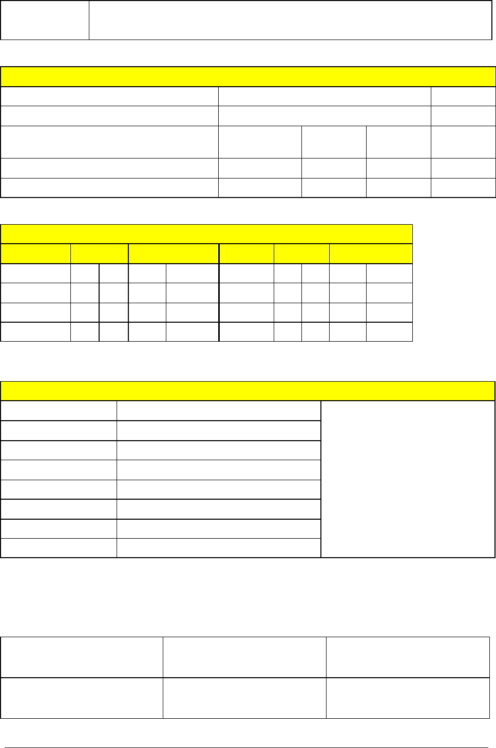
44 Issue 1 AIS Installation Manual
Vessel Name
Vessel and GNSS dimensions
Vessel length Metres
Vessel beam Metres
Internal
GNSS External
GNSS A External
GNSS B
GNSS antenna distance to Stern
Metres
GNSS antenna distance to Port side
Metres
RS-422 Setup
Port General Baud rate Port General Baud rate
Main On Off 4800 38400 Sen 1 On Off
4800
38400
Aux On Off 4800 38400 Sen 2 On Off
4800
38400
LR On Off 4800 38400 Sen 3 On Off
4800
38400
RTCM On Off 4800 38400 Sen 4 On Off
4800
38400
Installers Data
Company Name Stamp:
Technician’s Name
Address Line 1
Address Line 2
City / Town
Province / State
Post / Zip Code
Country
This is an acceptance record of the installation and commissioning of the AIS on-board
the above-mentioned vessel. 24-months Warranty is valid on signing this form.
Installer’s Signature Owners Representative’s
Signature Commissioning Date
Installer’s Name Owners Representative’s
Name

AIS Installation Manual Issue 1 45
10 Pre-Installation Inspection Record
1. Vessel Data ( Tick appropriately )
Vessel Name IMO Number
Flag State MMSI Number
Owner / Company Radio Call Sign
Office: On-Board Contact
Name & Position
Telephone Number(s)
GSM:
Office: Shore-based Contact
Name & Position
Telephone Number(s)
GSM:
Type of Vessel
Gross Tonnage gt
L.O.A
m
Beam m
Comments:
2. Installation ( Tick appropriately )
Ship’s Emergency Power Source & Location
Cable length to Transponder = m
Optional AC to DC Converter (89-029) Required
12 V DC 24 V DC 110 V AC 220 V AC
50 Hz 60 Hz
AIS Transponder Proposed Location
AIS Display Proposed Location
4 Twisted Pair + Drain Cable length to Transponder m
AIS GNSS Antenna Proposed Location
RG58 Cable length to Transponder = m
Optional Antenna Adapter (89-362) Required
AIS VHF Antenna Proposed Location
RG214 Cable length to Transponder = m
Optional VHF Antenna (89-020-001) Required
Optional Antenna Mast Mount (903-01) Required
Optional Antenna Mast/Bulkhead Mount (903-02) Required
AIS Pilot Plug* Proposed Location
Cable length to Transponder = m
Ship’s Ground Connection Location
Cable length to Transponder = m
Ship’s Alarm Panel Location
Cable length to Transponder = m
* If a Pilot Plug is fitted, a mains power supply for a PC should be made available nearby
Optional Installation Kit (89-038) Required
Comments:

46 Issue 1 AIS Installation Manual
Bridge Layout Drawing: Position of all parts & interface pick-off points
3. Heading Sensor(s)* ( Tick appropriately )
Source Option A Option B
Manufacturer
Model
Type GyroCompass GNSS Compass
Fluxgate Compass
Transmitting Magnetic Compass
GyroCompass GNSS Compass
Fluxgate Compass
Transmitting Magnetic Compass
Output NMEA Message
IEC 61162-2 RS422
Required:- HDT ROT**
Optional:- OSD
Required:- HDT ROT**
Optional:- OSD
If no NMEA
Optional Gyro Interface
Unit (89-028) Required
Synchro
Reference Voltage =
Phase Voltage = Frequency =
Ratio - 90:1 180:1 360:1
Synchro
Reference Voltage =
Phase Voltage = Frequency =
Ratio - 90:1 180:1 360:1
Stepper
Positive Step Negative Step
Step Voltage =
Ratio - 90:1 180:1 360:1
Stepper
Positive Step Negative Step
Step Voltage =
Ratio - 90:1 180:1 360:1
Location
Cable length to
Transponder
m
m
* Heading information is a mandatory sensor input to the AIS. A converter will be needed if the ship’s compass has no IEC61162 output.
** If a rate-of-turn indicator is available and it includes an IEC61162 output it should be connected to the AIS
Comments:

AIS Installation Manual Issue 1 47
4. Position Sensor(s)* ( Tick appropriately )
Source
Option A Option B
Manufacturer
Model
Type
GPS GLONASS Differential GPS GLONASS Differential
Output NMEA Message
IEC 61162-2 RS422
Required:- DTM GNS
GLL
RMC GBS RTE WPL
Optional:- GGA
Required:- DTM GNS
GLL RMC GBS RTE
WPL
Optional:- GGA
Location
Cable length to
Transponder
m
m
Antenna Location External Position Source
GNSS Antenna AIS Internal Position
Source GNSS Antenna Dimension
Limits
A = Distance to Bow
m
m
0- 511 m
B = Distance to Stern
m
m
0 – 511 m
C = Dist. to Port-Side
m
m
0 – 63 m
D = Dist. to Starboard
m
m 0 – 63 m
* Position information is a mandatory sensor input to the AIS.
Comments:
5. Speed Sensor(s)* ( Tick appropriately )
Source Option A Option B
Manufacturer
Model
Type Bottom Track Log Bottom Track Log
Output NMEA Message
IEC 611622-2 RS422
Required:- VBW Required:- VBW
Location
Cable length to
Transponder
m
m
* If a Bottom Track Log is available and it includes an IEC61162 output it should be connected to the AIS.
Comments:

48 Issue 1 AIS Installation Manual
6. ARPA / ATA RADAR(s) ( Tick appropriately )
Source Option A Option B
Manufacturer
Model
Type
In/Output NMEA
Message
IEC 61162-2 RS422
Location
Cable length to
Transponder
m
m
Comments:
7. ECDIS / ECS(s) ( Tick appropriately )
Source Option A Option B
Manufacturer
Model
Type
In/Output NMEA
Message
IEC 61162-2 RS422
Location
Cable length to
Transponder
m
m
Comments:
8. Notes
Include comments relative to installation: Cable routing, Deck glands to be opened, Hot work required, Interfacing, Mounting, Earthing,
etc…

AIS Installation Manual Issue 1 49
11 Glossary
4S Ship-to-Ship & Ship-to-Shore
AIS Automatic Identification System
ALM Alarm
ANT Antenna
ARPA Automatic Radar Plotting Aid
ATA Automatic Tracking Aid
AtoN Aid to Navigation
AUTO Automatic
AUX Auxiliary
BAT Battery
BIIT Built-In Integrity Test
BRG Bearing
BRILL Display Brilliance
CG Coast Guard
CH Channel
CHG Change
CLR Clear
CNCL Cancel
CNS Communication, Navigation & Surveillance
COG Course Over Ground
CONTR Contrast
CPA Closest Point of Approach
CPU Central Processing Unit
CSE Course
DEL Delete
DEST Destination
DG Dangerous Goods
DGLONASS Differential GLONASS
DGNSS Differential GNSS
DGPS Differential GPS
DISP Display
DIST Distance
DSC Digital Selective Calling
DTE Data Terminal Equipment
ECDIS Electronic Chart Display and Information
System
ECS Electronic Chart System
EGNOS European Geo-stationary Navigational
Overlay System
ENC Electronic Navigation Chart
ENT Enter
EPA Electronic Plotting Aid
EPFS Electronic Position Fixing System
EPIRB Electronic Position Indicating Radio
Beacon
ERR Error
ETA Estimated Time of Arrival
EXT External
FCC Federal Communications Commission
FREQ Frequency
GLO or
GLONASS Global Orbiting Navigation Satellite
System
GMDSS Global Maritime Distress and Safety
System
GND Ground
GNSS Global Navigation Satellite System
GPS Global Positioning System
GYRO Gyro Compass
HDG Heading
HS Hazardous Substances
HSC High Speed Craft
I/O Input / Output
IBS Integrated Bridge System
ID Identification
IEC International Electotechnical Commission
IMO International Maritime Organisation
IN Input
INFO Information
INS Integrated Navigation System
ITU-R International Telecommunications Union –
Radiocommunications Bureaux
KN Knots
L/L Latitude / Longitude
LAT Latitude
LON Longitude
LOST TGT Lost Target
M Metres
MAG Magnetic
MAN Manual
MED Marine Equipment Directive
MF/HF Medium Frequency/High Frequency
MID Maritime Identification Digit
MIN Minimum
MKD Minimum Keyboard and Display
MMSI Maritime Mobile Service Identity
MOB Man Overboard
MP Marine Pollutant
NAV Navigation
NM Nautical Mile
NUC Not Under Command
OOW Officer Of the Watch
OS Own Ship
OUT Output
PI Presentation Interface
POSN Position
PPU Portable Pilot Unit
PWR Power
RAIM Receiver Autonomous Integrity Monitoring
RNG Range
RORO Roll On, Roll Off
ROT Rate Of Turn
RR Range Rings
RTCM Radio Technical Commission for Maritime
services
RTE Route
Rx Receive / Receiver
SAR Search And Rescue
SEL Select
SOG Speed Over Ground
SPD Speed
SPEC Specification
STBD Starboard
STBY Standby
STW Speed Through Water
TCPA Time to Closest Point of Approach
TDMA Time Division Multiple Access
TGT Target
TPR Transponder
TRK Track
TSS Traffic Separation Scheme
TTG Time To Go
Tx Transmit / Transmitter
Tx/Rx Transceiver
AIS Universal Automatic Identification System
UHF Ultra High Frequency
UTC Universal Time Co-ordinate
VDU Visual Display Unit
VHF Very High Frequency
VOY Voyage
VSWR Virtual Standing Wave Ratio
VTS Vessel Traffic Systems
WAAS Wide Area Augmentation System
WCV Waypoint Closure Velocity
WGS World Geodetic System
WIG Wing In Ground
WPT Waypoint

50 Issue 1 AIS Installation Manua
This page contains no other data

AIS Installation Manual Issue 1 51
12 Commissioning guide
The sequence of operations given here MUST be performed in order to set essential
parameters of the AIS system, and to make it operational.
The Operation manual contains detailed information on the method of setting these parameters.
Refer to that manual if difficulty is found with any of the outline steps given below.
1. select “Setup mode: Ship's static data” by pressing and holding 'ENTER'
2. select “edit SHIP'S DATA”
3. enter service mode by using the service password (default 'SERVICE')
4. go to page "Setup mode: Configuration"
5. change the baud rate of each serial port in turn to match the baud rate of the external
equipment connected to that port
6. go to page “Setup mode: Ship’s static data”
7. enter valid data for 'MMSI', 'IMO', 'vessel' & 'call sign'
8. select 'vessel type'
9. enter 'beam' & 'length'
10. enter internal & external GNSS antenna positions
11. press 'Save SHIP'S DATA' to save settings
CAUTION: as soon as a valid MMSI number is saved, the AIS will begin operation. Allow at
least 2 minutes for the system to initialise and obtain a valid GNSS fix.
The next stage is to check that the sensors are operational.
12. select “Voyage mode: Current status”
13. check that all available sensors are recognised
14. temporarily disconnect the external GNSS signal (This will cause an alarm.)
15. check that the internal GNSS is providing data, and that the display indicates the
GNSS source as internal
16. reconnect the external GNSS signal. Check that the GNSS source is now external
Now change the service password:
17. select “Setup mode: Ship's static data”
18. select “edit SHIP'S DATA”
19. enter current service password (default 'SERVICE')
20. enter new password in 'change password' field
21. enter new password in ‘confirm password' field
22. press 'verify password' to store the new service password
This completes the entry of required parameters. The M-2 system is now fully operational.
If it becomes necessary to disable an alarm, refer to the Operation manual.