Secukey Technology SK3 Wireless Access Control Kit User Manual Mini Control Board Sboard
Secukey Technology Co., Ltd. Wireless Access Control Kit Mini Control Board Sboard
UserManual.wiki
>
Secukey Technology
>
SK3 User Manual
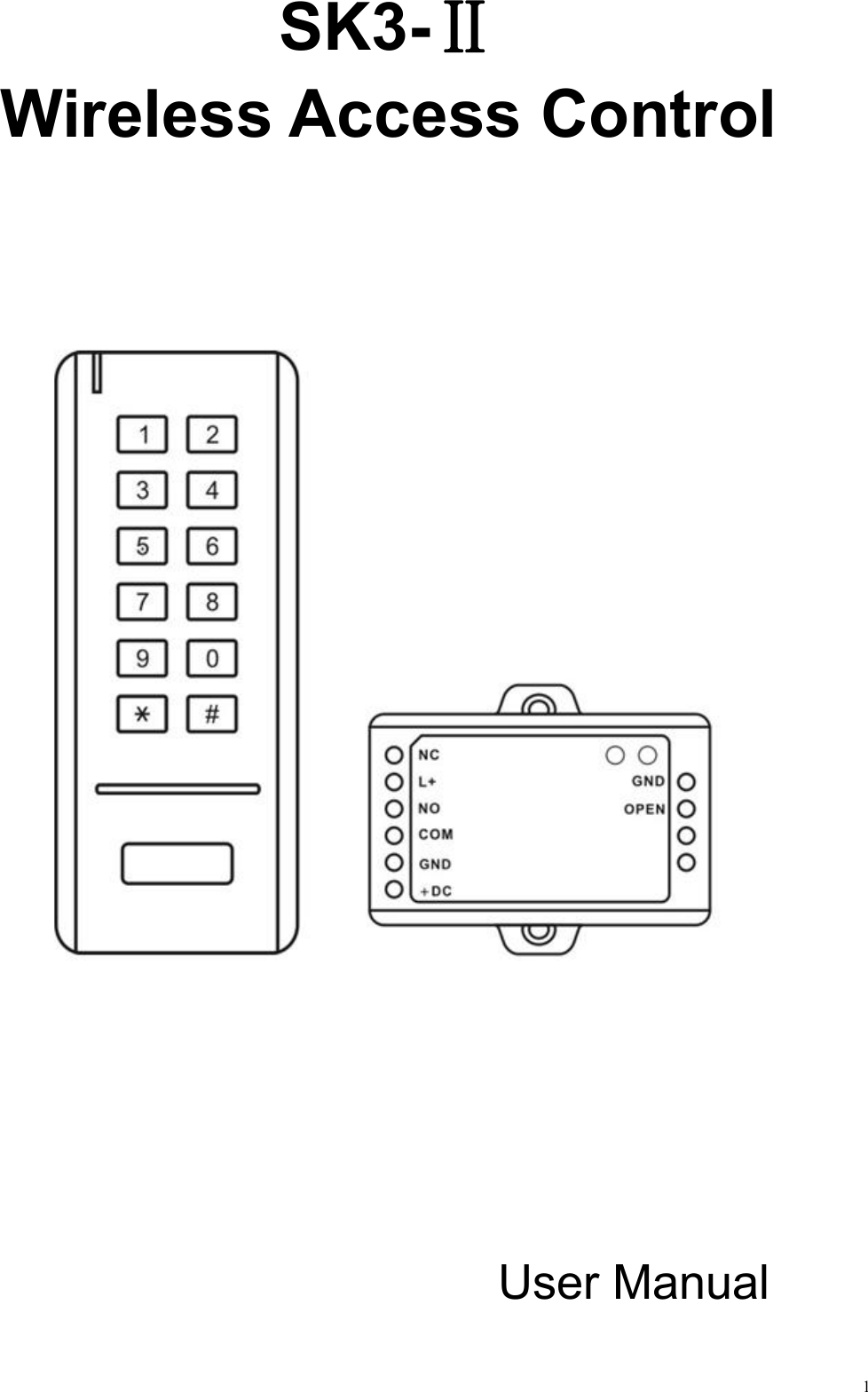
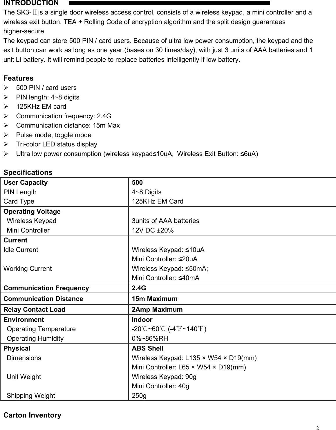
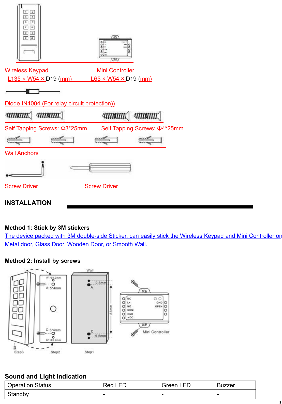
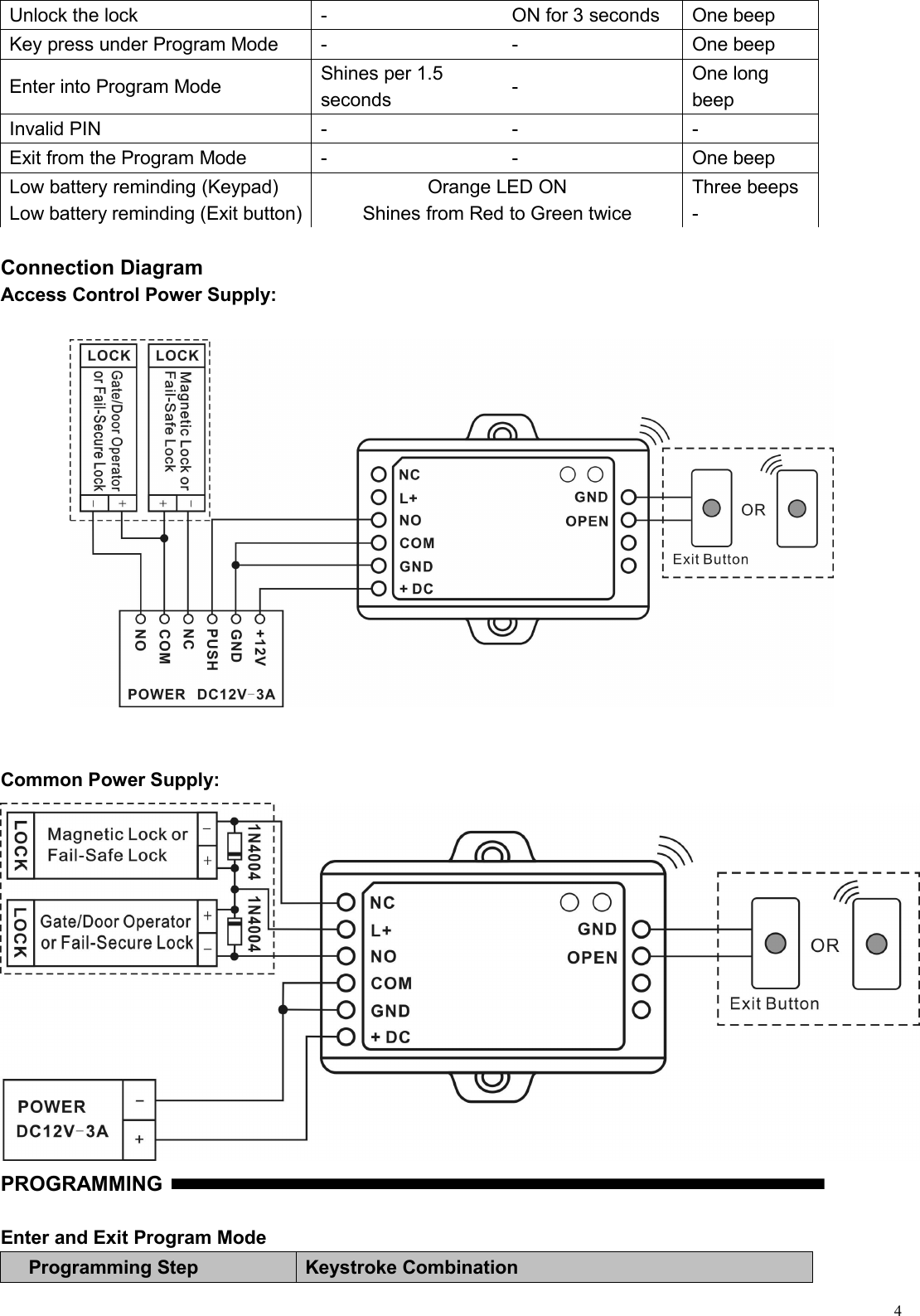
User Manual
Navigation menu
Upload a User Manual
Namespaces
Wiki Guide
HTML
PDF
Info
Views
User Manual
Discussion / Help
Navigation