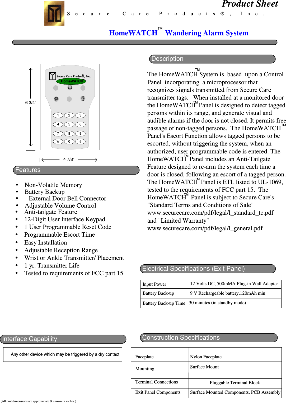
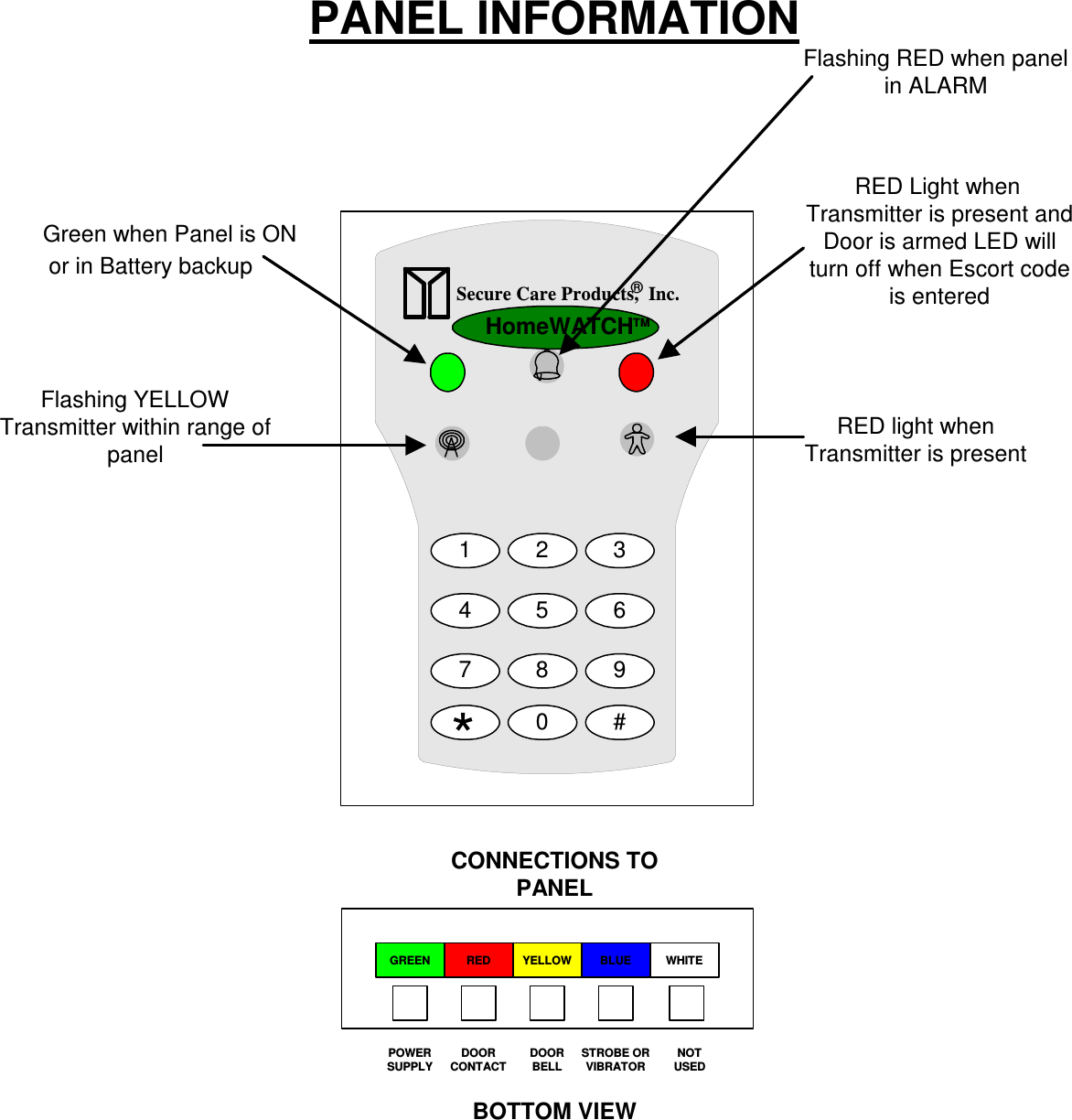
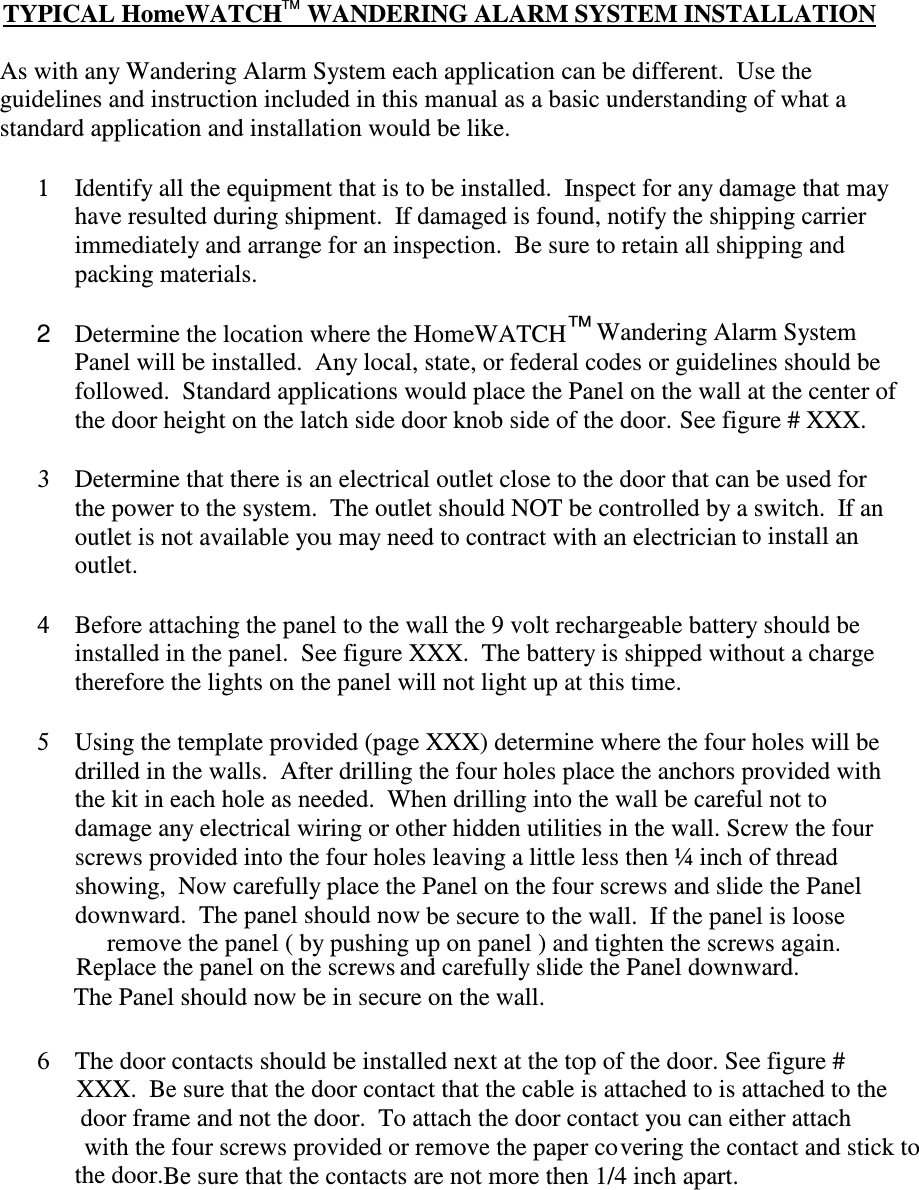
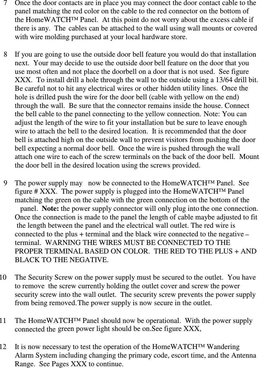
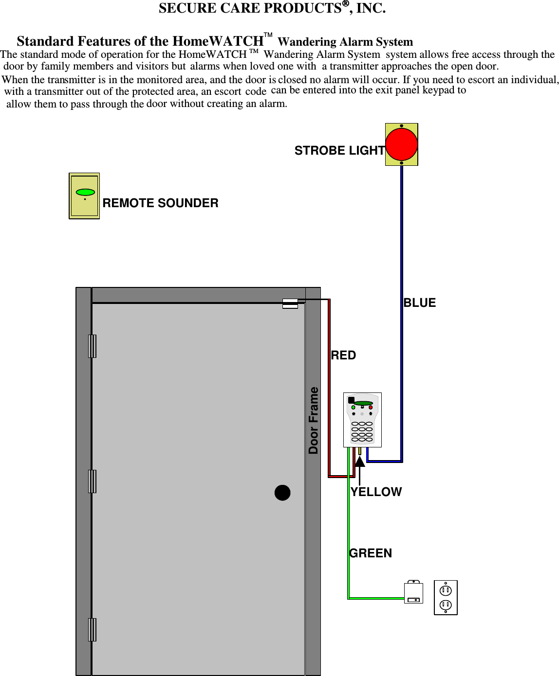
Secure Care HW433 Low Power Transceiver for Wandering Alarm System User Manual HomeWATCH
Secure Care Products Inc Low Power Transceiver for Wandering Alarm System HomeWATCH
UserManual.wiki
>
Secure Care
>
HW433 User Manual
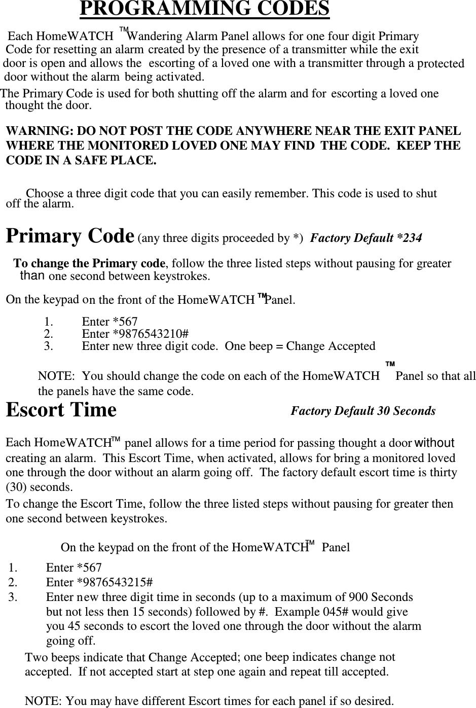
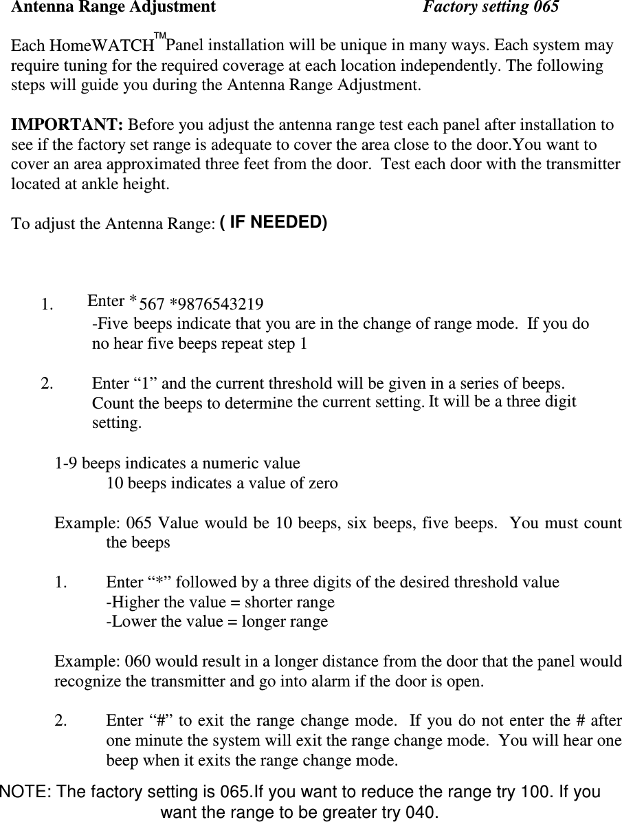
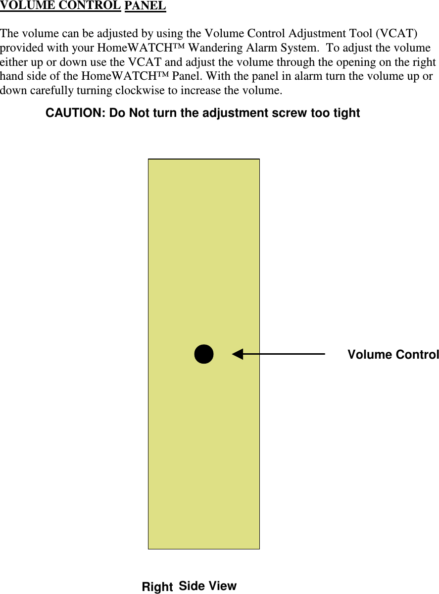
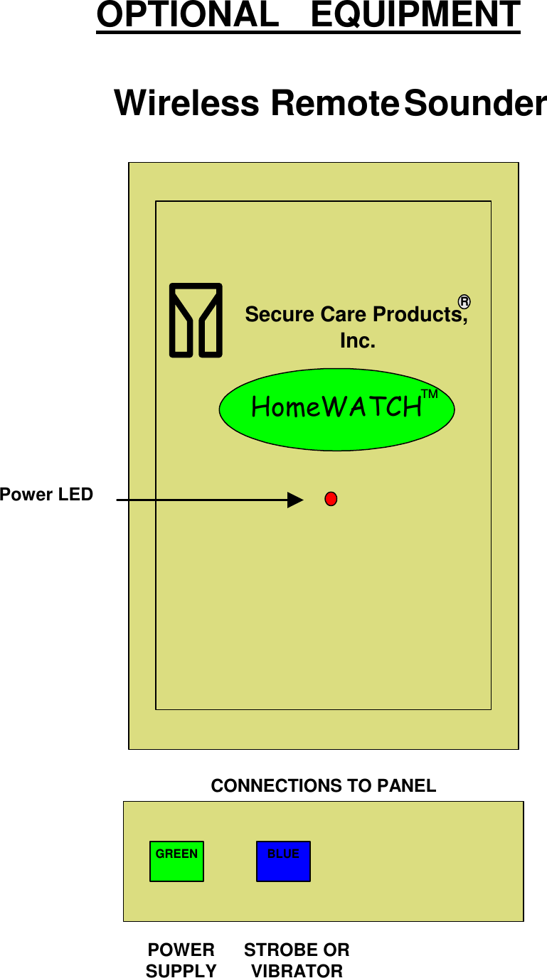
Users Manual
Navigation menu
Upload a User Manual
Namespaces
Wiki Guide
HTML
PDF
Info
Views
User Manual
Discussion / Help
Navigation