Secure Care HW433 Low Power Transceiver for Wandering Alarm System User Manual HomeWATCH
Secure Care Products Inc Low Power Transceiver for Wandering Alarm System HomeWATCH
Users Manual

Secure Care Products, Inc.
HomeWATCH
™
Installation & Owners
Manual
39 Chenell Drive, Concord NH 03301-8501 800-451-7917 Fax 603-227-0200 www.securecare.com
®
Safe at Home
TM
HomeWATCH Wandering Alarm System
TM

Panel Information
Installation of HomeWATCH System
Standard Features
Battery Replacement
Documentation and Testing
Transmitter and Door Testing Cut Sheet
Power Supply Connection
Door Contact Connection
Door Bell Connection
Transmitter Product Sheet
Transmitter Care .
Transmitter Warranty
Transmitter Strap Instruction
Programming .
Volume Control .
Optional Equipment
FCC Compliance Statement
Template use and Layout
Replacement Parts List
TABLE OF CONTENTS
Pg.3
Product Sheet
Pg.4
Pg.5
Pg.6
Pg.7
Pg.9
Pg.10
Pgs.11
Pg.12-13
Pg.14
Pg.15
Pg.16
Pgs.17
Pg.18
Pgs.19
Pg.20
Pgs.21-22
Pg.23
Pg.24-26
Tools Required
Pg.28
Introdution to HomeWATCH
Important Notice
TM
TM
Pg.29
Pg.30

INTRODUCTION
THANK YOU FOR PURCHASING A HomeWATCH™ WANDERING ALARM
SYSTEM
The HomeWATCH™ Wandering Alarm System operates as an alarm system that allows
normal traffic flow and will generate both a visual and audible alarm when a monitored
loved one exits the home through a monitored door. When the monitored loved one is in
the secure area, and the door is closed no alarm will occur. If they are in the secure area
and the door is opened the visual and audible alarm will occur.
READ ME FIRST
IMPORTANT NOTICES
This equipment is designed for adult use. Do not allow children to play with this product.
Do not leave or place exit code near the unit. Keep in a safe place.
Be sure to use the safety screw to attach the power supply to the wall outlet.
Warning –DO NOT plug the power supply into an outlet that is operated by a wall
switch.
Unit should not be placed in a location where extremes in temperature are present, such
as a radiator, a heater, near an air conditioner, etc.
Unit should always be tested after installation.
When cutting or drilling into wall do not damage electrical wiring and other hidden
utilities.
The HomeWATCH ™ Wandering Alarm System should be tested regularly to ensure its
continued operation.
Do not overload wall outlets and extension cords. This can increase risk of fire or
electric shock.
Use only the correct power supply provided with this product. Use of a different power
supply may damage the product.
Install this product securely on a stable surface
Observe all warnings and instructions marked on the product.
Read and understand all instructions in the owner’s manual.
Always follow basic safety precautions when using this product to reduce risk of injury,
fire, or electric shock.

TOOL REQUIRED
Philips Screw Drive
Hammer
Drill
Drill Bit (for the door bell ) 3/8
Flat Head Screw Driver
Wire Cutters
Driil bit (for the anchors)13/64
S e c u r e C a r e P r o d u c t s ® , I n c .
Features
Non-Volatile Memory
Product Sheet
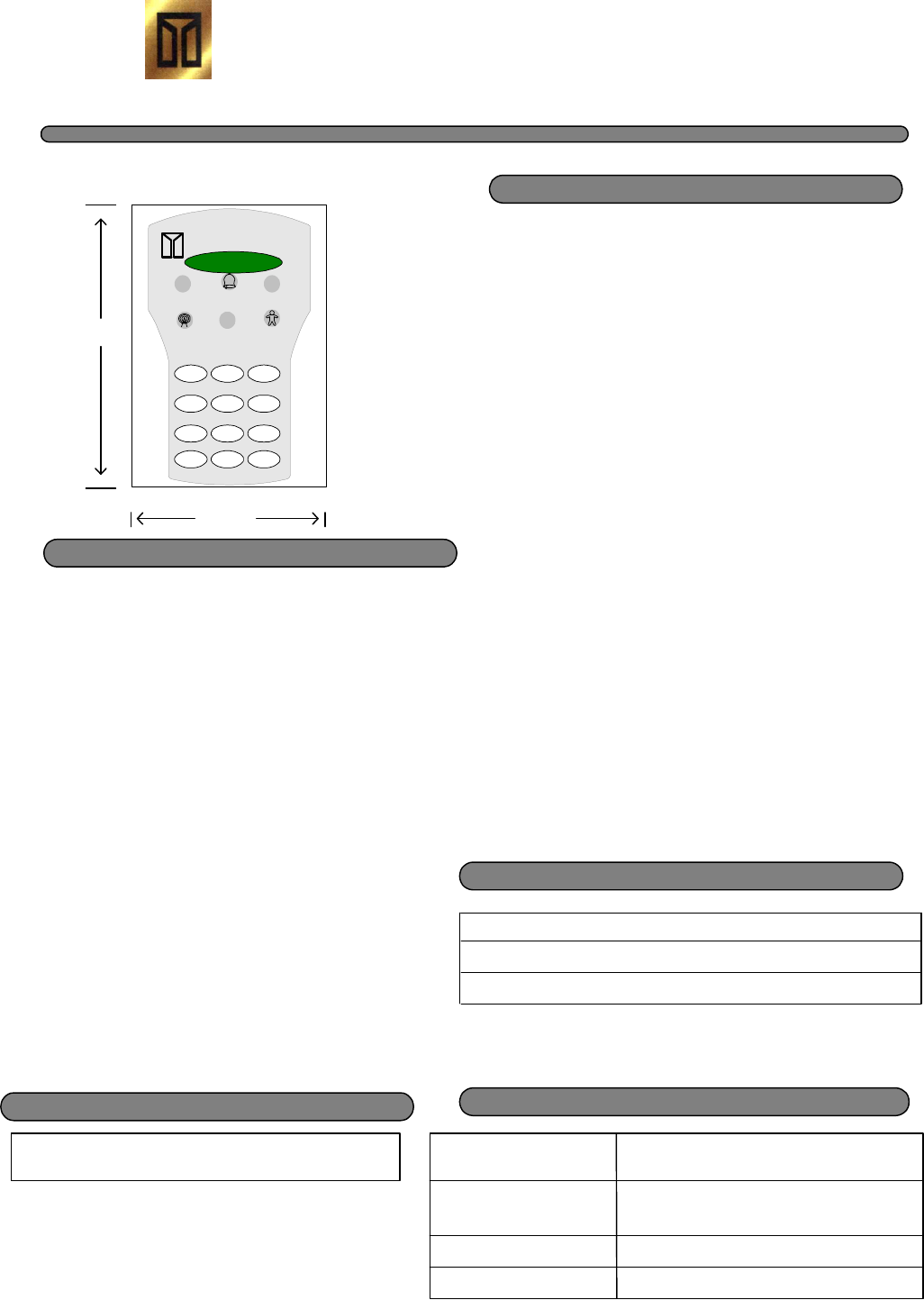
(All unit dimensions are approximate & shown in inches.)
Construction Specifications
Electrical Specifications (Exit Panel)
Input Power
Battery Back-up
Battery Back-up Time
12 Volts DC, 500mMA Plug-in Wall Adapter
9 V Rechargeable battery,120mAh min
30 minutes (in standby mode)
Interface Capability
6 3/4"
4 7/8"
Faceplate
Mounting
Terminal Connections
Exit Panel Components Surface Mounted Components, PCB Assembly
Pluggable Terminal Block
Surface Mount
Nylon Faceplate
Any other device which may be triggered by a dry contact
®
Secure Care Products, Inc.
1 2 3
4 5 6
7 8 9
0 #
*
HomeWATCH
TM
Battery Backup
External Door Bell Connector
Adjustable Volume Control
Anti-tailgate Feature
12-Digit User Interface Keypad
1 User Programmable Reset Code
Programmable Escort Time
Easy Installation
Adjustable Reception Range
Wrist or Ankle Transmitter/ Placement
1 yr. Transmitter Life
Tested to requirements of FCC part 15
HomeWATCH
TM
Wandering Alarm System
Description
The HomeWATCH System is based upon a Control
Panel incorporating a microprocessor that
recognizes signals transmitted from Secure Care
transmitter tags. When installed at a monitored door
the HomeWATCH Panel is designed to detect tagged
persons within its range, and generate visual and
audible alarms if the door is not closed. It permits free
passage of non-tagged persons. The HomeWATCH
Panel's Escort Function allows tagged persons to be
escorted, without triggering the system, when an
authorized, user programmable code is entered. The
HomeWATCH Panel includes an Anti-Tailgate
Feature designed to re-arm the system each time a
door is closed, following an escort of a tagged person.
The HomeWATCH Panel is ETL listed to UL-1069,
tested to the requirements of FCC part 15. The
HomeWATCH Panel is subject to Secure Care's
"Standard Terms and Conditions of Sale"
www.securecare.com/pdf/legal/l_standard_tc.pdf
and "Limited Warranty"
www.securecare.com/pdf/legal/l_general.pdf
TM
TM
TM
TM
TM
TM
®
Secure Care Products, Inc.
1 2 3
4 5 6
7 8 9
0 #
*
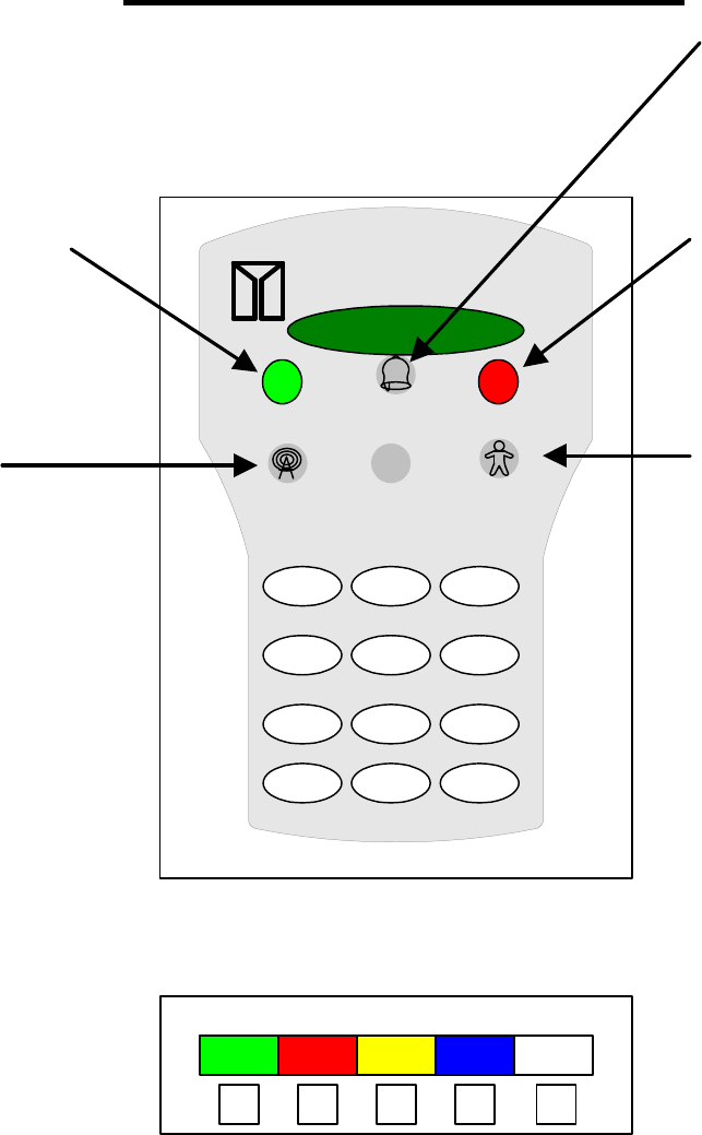
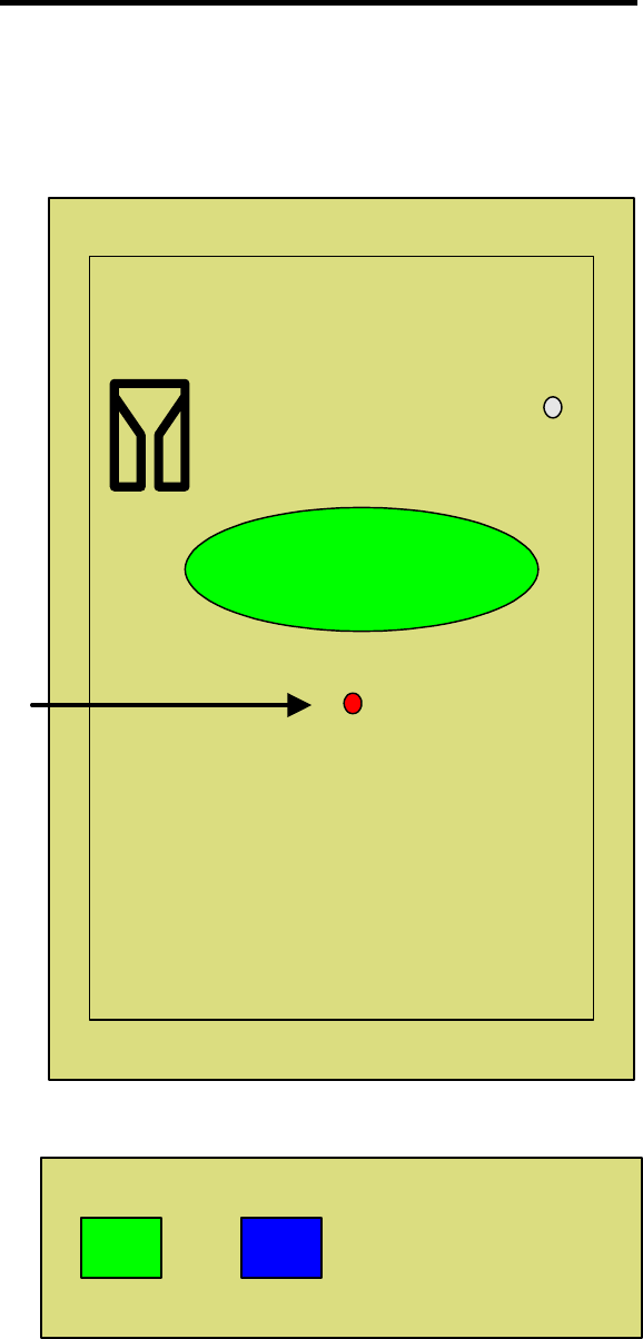
HomeWATCH
Flashing YELLOW
Transmitter within range of
panel
RED light when
Transmitter is present
Flashing RED when panel
in ALARM
PANEL INFORMATION
GREEN RED YELLOW BLUE WHITE
POWER
SUPPLY
DOOR
CONTACT
DOOR
BELL
STROBE OR
VIBRATOR
NOT
USED
BOTTOM VIEW
CONNECTIONS TO
PANEL
TM
Green when Panel is ON
or in Battery backup
RED Light when
Transmitter is present and
Door is armed LED will
turn off when Escort code
is entered

The Panel should now be in secure on the
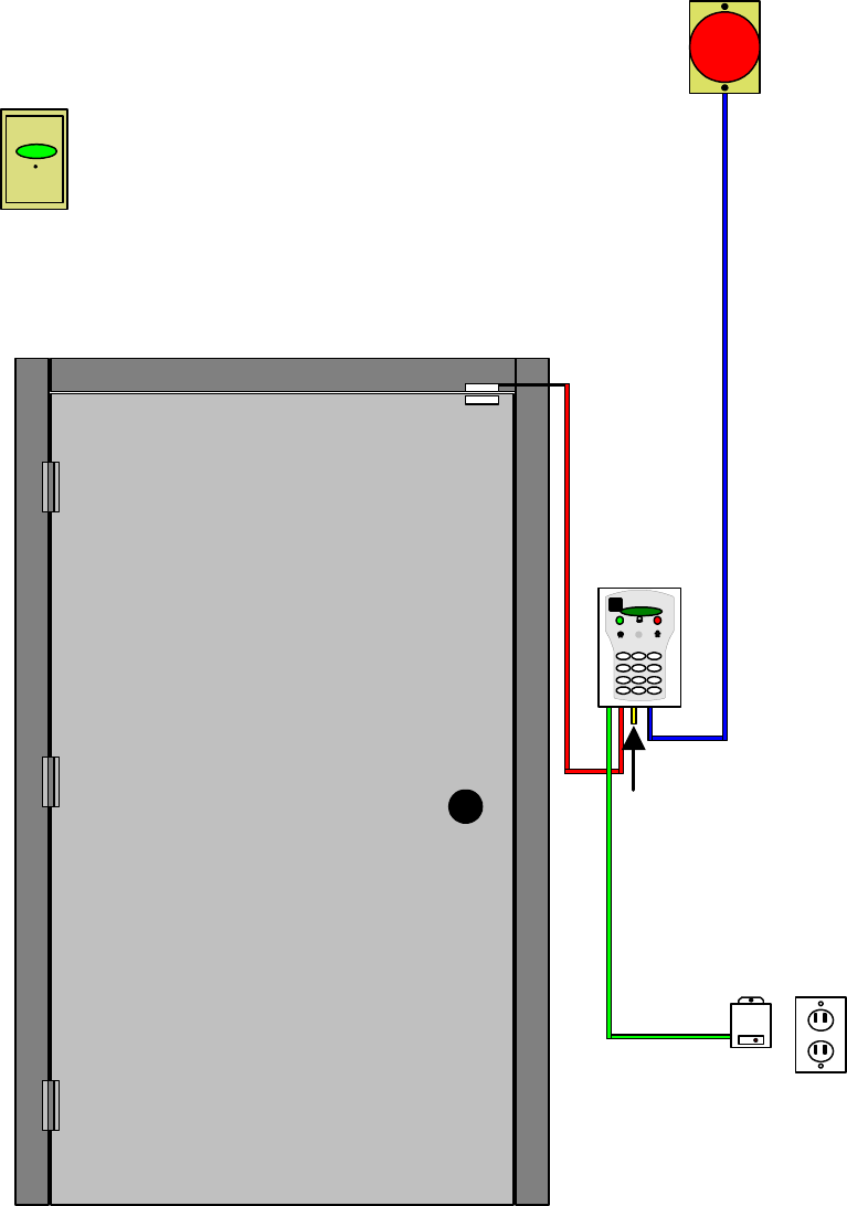
TYPICAL HomeWATCH WANDERING ALARM SYSTEM INSTALLATION
As with any Wandering Alarm System each application can be different. Use the
guidelines and instruction included in this manual as a basic understanding of what a
standard application and installation would be like.
TM
6
The door contacts should be installed next at the top of the door. See figure #
XXX. Be sure that the door contact that the cable is attached to is attached to the
door frame and not the door. To attach the door contact you can either attach
with the four screws provided or remove the paper covering the contact and stick to
the door.Be sure that the contacts are not more then 1/4 inch apart.
4
Before attaching the panel to the wall the 9 volt rechargeable battery should be
installed in the panel. See figure XXX. The battery is shipped without a charge
therefore the lights on the panel will not light up at this time.
5
Using the template provided (page XXX) determine where the four holes will be
drilled in the walls. After drilling the four holes place the anchors provided with
the kit in each hole as needed. When drilling into the wall be careful not to
damage any electrical wiring or other hidden utilities in the wall. Screw the four
screws provided into the four holes leaving a little less then ¼ inch of thread
showing, Now carefully place the Panel on the four screws and slide the Panel
downward. The panel should now be secure to the wall. If the panel is loose
remove the panel ( by pushing up on panel ) and tighten the screws again.
wall.
Replace the panel on the screws and carefully slide the Panel downward.
1
Identify all the equipment that is to be installed. Inspect for any damage that may
have resulted during shipment. If damaged is found, notify the shipping carrier
immediately and arrange for an inspection. Be sure to retain all shipping and
packing materials.
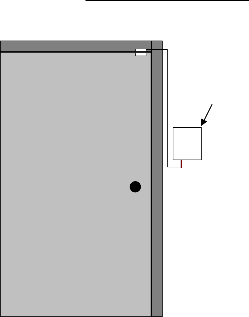
Determine the location where the HomeWATCH Wandering Alarm System
Panel will be installed. Any local, state, or federal codes or guidelines should be
followed. Standard applications would place the Panel on the wall at the center of
the door height on the latch side door knob side of the door. See figure # XXX.
3
Determine that there is an electrical outlet close to the door that can be used for
the power to the system. The outlet should NOT be controlled by a switch. If an
outlet is not available you may need to contract with an electrician to install an
outlet.
™
2
7
Once the door contacts are in place you may connect the door contact cable to the
panel matching the red color on the cable to the red connector on the bottom of
the HomeWATCH™ Panel. At this point do not worry about the excess cable if
there is any. The cables can be attached to the wall using wall mounts or covered
with wire molding purchased at your local hardware store.
8
If you are going to use the outside door bell feature you would do that installation
next. Your may decide to use the outside door bell feature on the door that you
use most often and not place the doorbell on a door that is not used. See figure
XXX. To install drill a hole through the wall to the outside using a 13/64 drill bit.
Be careful not to hit any electrical wires or other hidden utility lines. Once the
hole is drilled push the wire for the door bell (cable with yellow on the end)
through the wall. Be sure that the connector remains inside the house. Connect
the bell cable to the panel connecting to the yellow connection. Note: You can
adjust the length of the wire to fit your installation but be sure to leave enough
wire to attach the bell to the desired location. It is recommended that the door
bell is attached high on the outside wall to prevent visitors from pushing the door
bell expecting a normal door bell. Once the wire is pushed through the wall
attach one wire to each of the screw terminals on the back of the door bell. Mount
the door bell in the desired location using the screws provided.
9
The power supply may now be connected to the HomeWATCH™ Panel. See
figure # XXX. The power supply is plugged into the HomeWATCH™ Panel
matching the green on the cable with the green connection on the bottom of the
panel.
Note:
the power supply connector will only plug into the one connection.
Once the connection is made to the panel the length of cable maybe adjusted to fit
the length between the panel and the electrical wall outlet. The red wire is
connected to the plus + terminal and the black wire connected to the negative –
terminal. WARNING THE WIRES MUST BE CONNECTED TO THE
PROPER TERMINAL BASED ON COLOR. THE RED TO THE PLUS + AND
BLACK TO THE NEGATIVE.
10
The Security Screw on the power supply must be secured to the outlet. You have
to remove the screw currently holding the outlet cover and screw the power
security screw into the wall outlet. The security screw prevents the power supply
from being removed.
11
The HomeWATCH™ Panel should now be operational. With the power supply
connected the green power light should be on.See figure XXX,
12
It is now necessary to test the operation of the HomeWATCH™ Wandering
Alarm System including changing the primary code, escort time, and the Antenna
Range. See Pages XXX to continue.
The power supply is now secure in the outlet.
Door Frame
RED
GREEN
YELLOW
BLUE
STROBE LIGHT
REMOTE SOUNDER
When the transmitter is in the monitored area, and the door is closed no alarm will occur. If you need to escort an individual,
SECURE CARE PRODUCTS
, INC.
The standard mode of operation for the HomeWATCH Wandering Alarm System system allows free access through the
Wandering Alarm System
family members and visitors but alarms when loved one with a transmitter approaches the open door.door by
door without creating an alarm.
pass through the allow them to
can be entered into the exit panel keypad to
with a transmitter out of the protected area, an escort code
TM
Standard Features of the HomeWATCH
TM
BATTERY REPLACEMENT
The battery must be replaced with a 9 volt rechargeable battery. The battery must be
replaced at least once a year. Please dispose of the battery properly. Replacement
batteries may be purchased by calling Secure Care Products®, Inc. at 1 -800-451-7917.
To replace the battery remove the HomeWATCH ™ panel(s) from the wall carefully and
on the back of the unit slide/remove the small door at the top of the panel. Replace the
battery and replace the door. Return the HomeWATCH™ panel to the wall.
9 volt RECHARGEABLE
Battery
+ -
Cover Plate for
Battery
RED BLACK
+
-

DOCUMENTATION AND TESTING
WEEKLY TRANSMITTER TESTING
Each transmitter should be tested
weekly
to ensure it is working properly. The
transmitter should be checked for expiration date at this time.
A documented test of the ankle or wrist transmitter and exit system must be made
each
week.
The procedure involves using a HomeWATCH ™ transmitter and the
HomeWATCH™ exit panel and documenting the performance of the transmitter and the
exit system.
Attached is a weekly transmitter and panel testing log which you may find useful to
record test dates.

Transmitter and door testing, to be performed weekly
EXIT PANEL
LOCATION TEST DATE
EXPIRATION
DATE ALARM SOUNDS TESTED BY Pass or Fail COMMENTS
YES / NO
YES / NO
YES / NO
YES / NO
YES / NO
YES / NO
YES / NO
YES / NO
YES / NO
YES / NO
YES / NO
YES / NO
YES / NO
YES / NO
YES / NO
YES / NO
YES / NO
YES / NO
YES / NO
YES / NO
YES / NO
YES / NO
YES / NO
YES / NO
YES / NO
HomeWATCH
TM
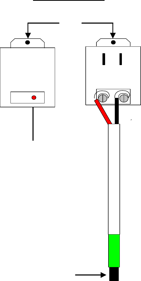
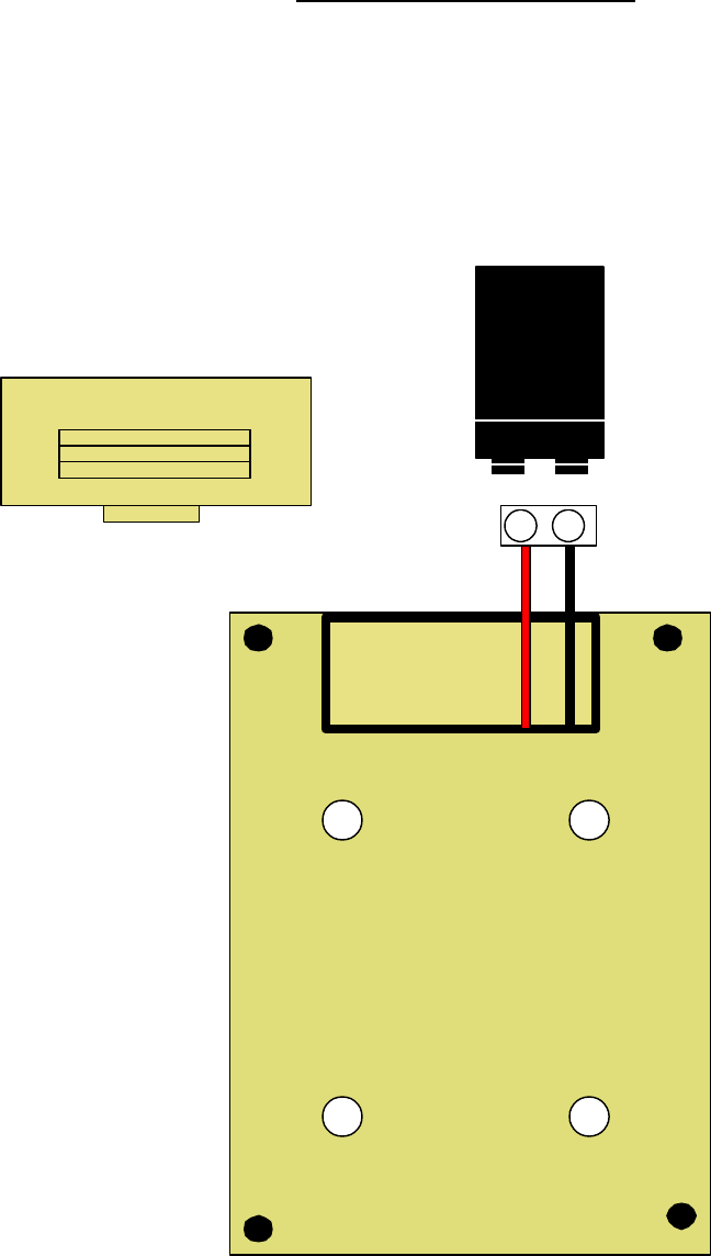
POWER SUPPLY
SECURITY
SCREW
+-
OUTPUT
RED
BLACK
CONNECTION CLIP
TO PANEL
BACK
WIRE TO THE HOMEWATCH
PANEL
GREEN
Red indicator power is ON
NOTE: Power Supply is
plugged into wall outlet
near panel. Security screw
used to secure power
supply to the outlet
NOTE: Plugs into bottom
of panel matching green
on the cable to the green
connection on the
HomeWATCH panel
TM
AC POWER
FRONT
RED
HomeWATCH
TM
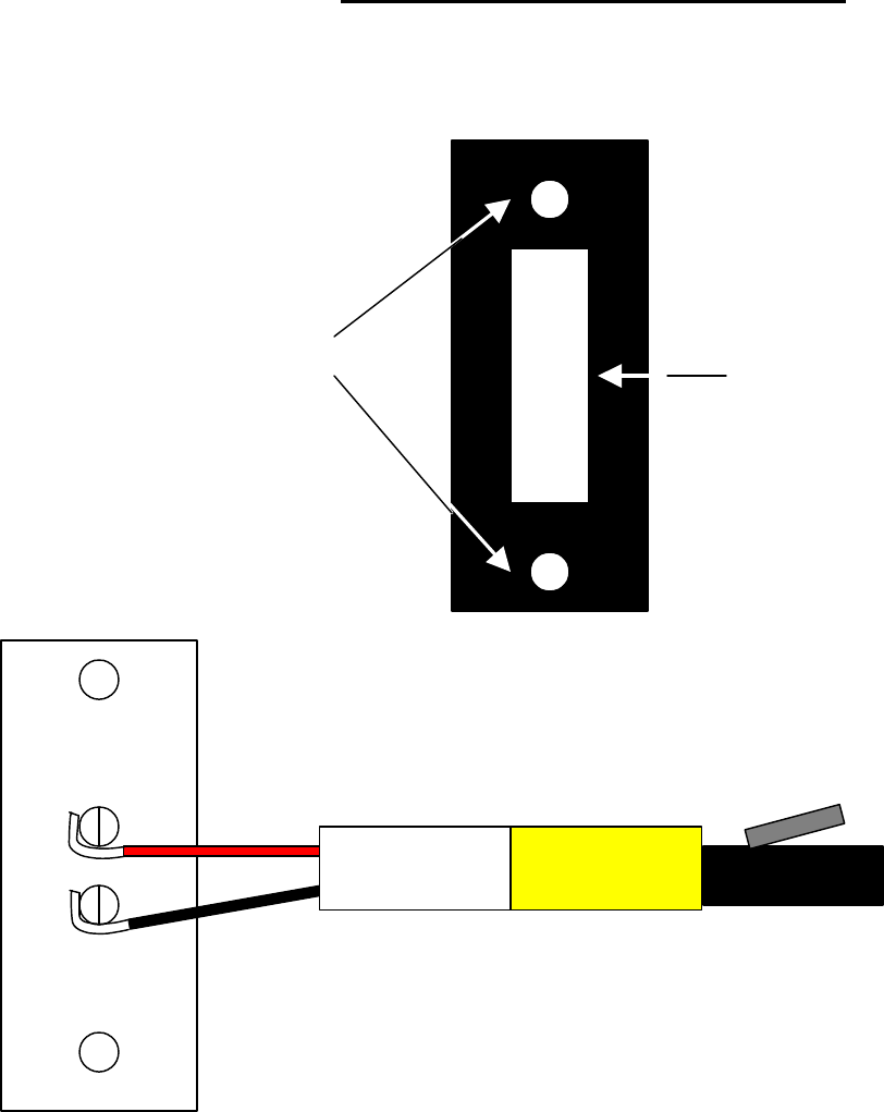
DOOR CONTACT CONNECTION
Door contacts maybe placed either on the top or side of the door.
They should be placed on the door knob side of the door.
NOTE: Plugs into the
bottom of panel
matching red on the
cable with red connector
on panel.
The RED wrapped cable is used for the Door contacts and will plug into the
HomeWATCH panel. Polarity does not matter.
IMPORTANT: The door contacts should not be more than 1/4 inch apart.
TM
HomeWATCH Panel
TM
DOOR BELL CONNECTION
The Door Bell is used to escort a monitored loved one from the outside through the
armed door without having the HomeWATCH Panel going into alarm
TM
SCREW HOLES PUSH BUTTON DOOR BELL
YELLOW
RED
BLACK CONNECTION TO PANEL
FRONT
Plugs into bottom of panel
matching Yellow on the
cable to the Yellow
connector on the panel.
To Install-
If installing the door bell outside, drill a hole through the wall using a 13/64 bit. Pass the cable
through the hole being sure the connector is on the inside of your home and near the panel.
Attach one wire to each of the screw terminals on the back of the door bell. Mount the door
bell in desired location using the screws provided.
NOTE CAUTION:
wall to prevent visitors from pushing the door bell expecting a normal door bell.
It is recommened that the door bell should be placed up high on the outside
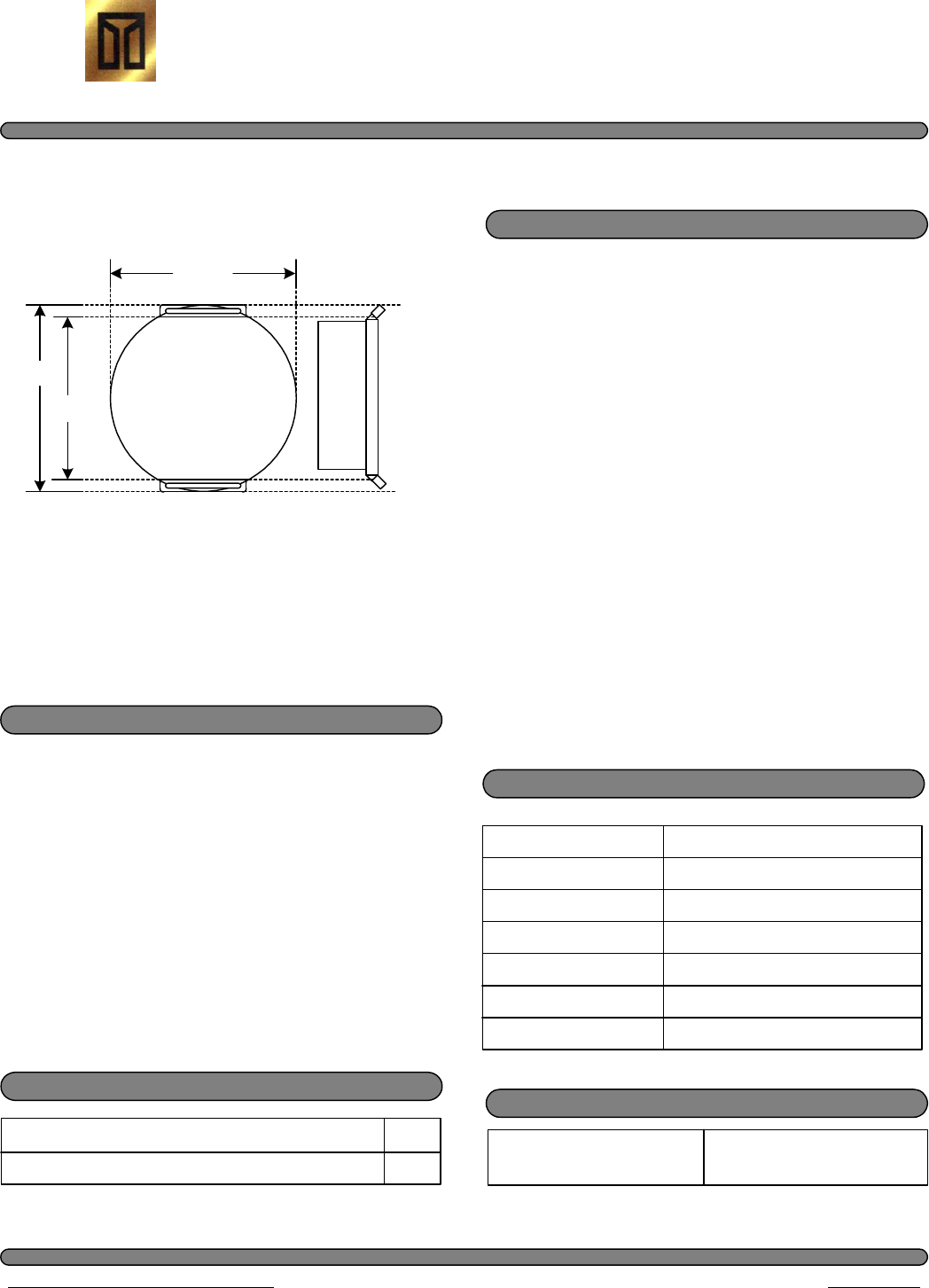
(All unit dimensions are approximate.)
S e c u r e C a r e P r o d u c t s ® , I n c .
HomeWATCH Wandering Alarm System
Adult Transmitter
Features
Light Weight
Attractive White Case
Long Life One (1) Year Life
Expectancy
Active Transmission
Water Tight
Durable Polycarbonate Plastic
Does Not Interfere With Other
Medical Equipment
Material Included
Sealed Active Transmitter
Hypo-allergenic, Water Proof, Transmitter Strap
1
1
Electrical Specifications
Power Supply
Max. Current Draw
Operating Frequency
Signal Output Power
Output Signal Type
Lithium 3 Volt Battery
10 Milli Amps
13.56 MHz
about 1 mW
Active, Pulsed Signal
Pulse Separation 400 to 500 ms
Pulse Length 1 millisecond
Construction Specifications
Case Construction Material Molded, Durable,
Polycarbonate Plastic
CONTENT SUBJECT TO CHANGE WITHOUT NOTICE REV A 06/01/2000
Product Sheet
©2000 Secure Care Products®, Inc. All Rights Reserved
39 Chenell Drive Concord, NH 03301-8501 603.223.0745 / 1.800.451.7917 Fax 603.227.0200 http:// www.securecare.com
TM
transmitter frequency and have the to the
intelligence to recognize this transmitter.
The A22350900 is water tight and can be
submerged in water without damaging the
unit. The A22350900 has an expiration
date engraved into the front cover and the
unit should be disposed of properly when
the expiration date has been reached.
Description
The A22350900 is an active transmitter
that is sending out a Radio Frequency
(RF) Signal. The A22350900 should
send out this RF signal for (1) year. The
HomeWATCH Wandering Alarm System
components that areshould consist of tuned
Part # A22350900
1.54"
(39.12mm)
1.24"
(31.50mm)
1.33"
(33.78mm)

The transmitter is water-tight and designed to remain on the loved one for a specified number of months.
Whirlpools, bathing, medical testing, etc. and washing the transmitter with mild soap or mild disinfectant, should
have no effect on the transmitter.
However, soaking or washing in alcohol, alcohol-based, or petroleum-based
products is prohibited.
HYGIENE AND SKIN CARE
Proper care should be given to the skin area around the ankle or wrist transmitter. Lotion should be applied
morning and evening, more often when needed. For those few loved ones whose skin is extremely sensitive, it is
suggested that a light cotton sock or nylon hose type material be slipped over the skin and under the transmitter.
Normal ankle or wrist transmitter application calls for two fingertips of slack between the strap and the ankle or
wrist.
In the likelihood the transmitter strap becomes soiled, discolored or torn, it may be easily replaced. Simply
cut off the old strap and slide a new strap down through a slot on one side of the transmitter case, under the curved
bottom of the transmitter and up through the opposite slot. Place the curved side of the transmitter with the new strap
touching the skin of the ankle or wrist before fastening.
WHEELCHAIR RESTRICTIONS
If the loved one is confined to a wheelchair, but still able to get up and walk, the transmitter must be worn
on the ankle of a leg that is
not
elevated. All transmitters
must be worn on the ankle or wrist
. If both legs are
elevated, and the resident is not capable of getting up and walking, then the transmitter may be put in the upright
position on the rod/leg above the wheel of the wheelchair.
RENEWALS
Transmitters will be engraved with the expiration date on the face of the transmitter.
It is the responsibility of the customer to order the renewal transmitters required in order to avoid the risk of aloved
one wearing an expired transmitter. Allow a manufacturing lead-time of approximately two weeks when ordering
transmitters.
All warranties on transmitters expire one (1) years from the shipping date. Secure Care Products
, Inc. must
stress the importance of replacing expired ankle or wrist transmitters immediately.
TRANSMITTER CARE AND USE

ONE YEAR TRANSMITTER WARRANTY
Transmitters are warranted for one (1) years from date of shipment. If within the one (1) year warranty
period a transmitter is not performing to our specification, CALL our toll free number (1-800-451-7917), for a
TXRA (Transmitter Return Authorization) BEFORE returning any Transmitter.
A replacement transmitter will be sent (to complete the end of the original warranty), along with a postage paid
label marked with a Return Authorization number. Simply replace the suspect transmitter with the replacement and
send it back to Secure Care Products
within 15 days with name and address, and the TXRA Number displayed,
along with a description of the transmitter problem.
When the transmitter is returned to Secure Care Products
, Inc., it is tested on a system similar to that in the
home to verify that the transmitter is not working to our specifications.
.
If the transmitter tests properly, and is in good working condition, the individual may be charged a prorated
amount up to the original due date, as well as freight charges incurred.
If the transmitter is physically damaged, or has been soaked or washed in alcohol, you will be charged the
full replacement transmitter charge.
If the suspect transmitter is not returned to us within the 15-day period, the individual will be charged the
prorated transmitter amount.
However, if the transmitter is returned within the 15-day period and does not pass our testing procedures
there is no charge to the individual for the repla
cement.
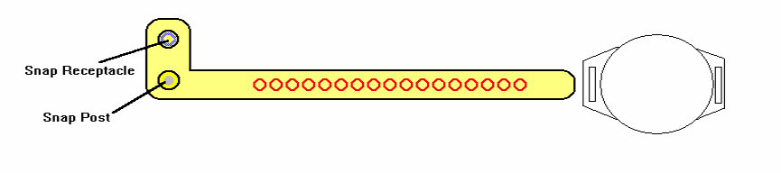
STRAP INSTRUCTIONS
1. Place the band through the slots in the transmitter, making sure that the strap is
underneath the curved side and that the curved side is towards the loved one ankle or
wrist. Keep two fingers between the band and the ankle or wrist to allow room for
swelling to occur.
2. Place the Snap Post through the nearest hole.
3. Fold the Snap Receptacle down to accept the Snap Post and press together
firmly until they snap securely.
4. Cut off excess material
To ensure proper operation of the Transmitter, it must be in an upright (or
vertical) position
on the ankle or wrist
.
Do Not
soak the Transmitter in alcohol, alcohol-based or petroleum based products.
It is acceptable to wash the Transmitter with a mild disinfectant or soap and water.
Information may be written on the strap using a permanent marker.
Transmitter straps are sold in increments of one (1) dozen, plus UPS shipping and
handling.
If you have any questions, please do not hesitate to call our
Toll Free
number
1-800-451-7917.
Transmitters returned to Secure Care Products
without prior approval may
incur
additional charges
to your account.
NOTE: Do not put the snap post into the snap Receptacle until the transmitter is located
in the proper position. Once snapped together you cannot unsnap the strap.

WARNING: DO NOT POST THE CODE ANYWHERE NEAR THE EXIT PANEL
WHERE THE MONITORED LOVED ONE MAY FIND THE CODE. KEEP THE
CODE IN A SAFE PLACE.
Primary Code
(any three digits proceeded by *)
Factory Default *234
To change the Primary code
, follow the three listed steps without pausing for greater
one second between keystrokes.
On the keypad on the front of the HomeWATCH Panel.
than
Escort Time
Each HomeWATCH panel allows for a time period for passing thought a door
creating an alarm. This Escort Time, when activated, allows for bring a monitored loved
one through the door without an alarm going off. The factory default escort time is thirty
(30) seconds.
without
To change the Escort Time, follow the three listed steps without pausing for greater then
one second between keystrokes.
On the keypad on the front of the HomeWATCH Panel
Choose a three digit code that you can easily remember. This code is used to shut
off the alarm.
TM
1. Enter *567
2. Enter *9876543215#
3. Enter new three digit time in seconds (up to a maximum of 900 Seconds
but not less then 15 seconds) followed by #. Example 045# would give
you 45 seconds to escort the loved one through the door without the alarm
going off.
TM
PROGRAMMING CODES
door is open and allows the
The Primary Code is used for both shutting off the alarm and for escorting a loved one
escorting of a loved one with a transmitter through a p
door without the alarm
Each HomeWATCH Wandering Alarm Panel allows for one four digit Primary
TM
Code for resetting an alarm created by the presence of a transmitter while the exit
rotected
being activated.
thought the door.
Two beeps indicate that Change Accepted; one beep indicates change not
accepted. If not accepted start at step one again and repeat till accepted.
NOTE: You may have different Escort times for each panel if so desired.
1. Enter *567
2. Enter *9876543210#
3. Enter new three digit code. One beep = Change Accepted
Factory Default 30 Seconds
NOTE: You should change the code on each of the HomeWATCH Panel so that all
the panels have the same code.
TM
TM
Antenna Range Adjustment
Factory setting 065
Each HomeWATCH Panel installation will be unique in many ways. Each system may
require tuning for the required coverage at each location independently. The following
steps will guide you during the Antenna Range Adjustment.
IMPORTANT:
Before you adjust the antenna range test each panel after installation to
see if the factory set range is adequate to cover the area close to the door.You want to
cover an area approximated three feet from the door. Test each door with the transmitter
located at ankle height.
To adjust the Antenna Range:
TM
1. Enter *567 *9876543219
-Five beeps indicate that you are in the change of range mode. If you do
no hear five beeps repeat step 1
2. Enter “1” and the current threshold will be given in a series of beeps.
Count the beeps to determine the current setting. It will be a three digit
setting.
1-9 beeps indicates a numeric value
10 beeps indicates a value of zero
Example: 065 Value would be 10 beeps, six beeps, five beeps. You must count
the beeps
1. Enter “*” followed by a three digits of the desired threshold value
-Higher the value = shorter range
-Lower the value = longer range
Example: 060 would result in a longer distance from the door that the panel would
recognize the transmitter and go into alarm if the door is open.
2. Enter “#” to exit the range change mode. If you do not enter the #
after
one minute the system will exit the range change mode. You will hear one
beep when it exits the range change mode.
( IF NEEDED)
NOTE: The factory setting is 065.If you want to reduce the range try 100. If you
want the range to be greater try 040.

The volume can be adjusted by using the Volume Control Adjustment Tool (VCAT)
provided with your HomeWATCH™ Wandering Alarm System. To adjust the volume
either up or down use the VCAT and adjust the volume through the opening on the right
hand side of the HomeWATCH™ Panel. With the panel in alarm turn the volume up or
down carefully turning clockwise to increase the volume.
Side View
Volume Control
CAUTION: Do Not turn the adjustment screw too tight
Right
VOLUME CONTROL PANEL
OPTIONAL EQUIPMENT
Power LED
Wireless RemoteSounder
GREEN
POWER
SUPPLY
STROBE OR
VIBRATOR
CONNECTIONS TO PANEL
BLUE
HomeWATCH
TM
Secure Care Products,
Inc.
R
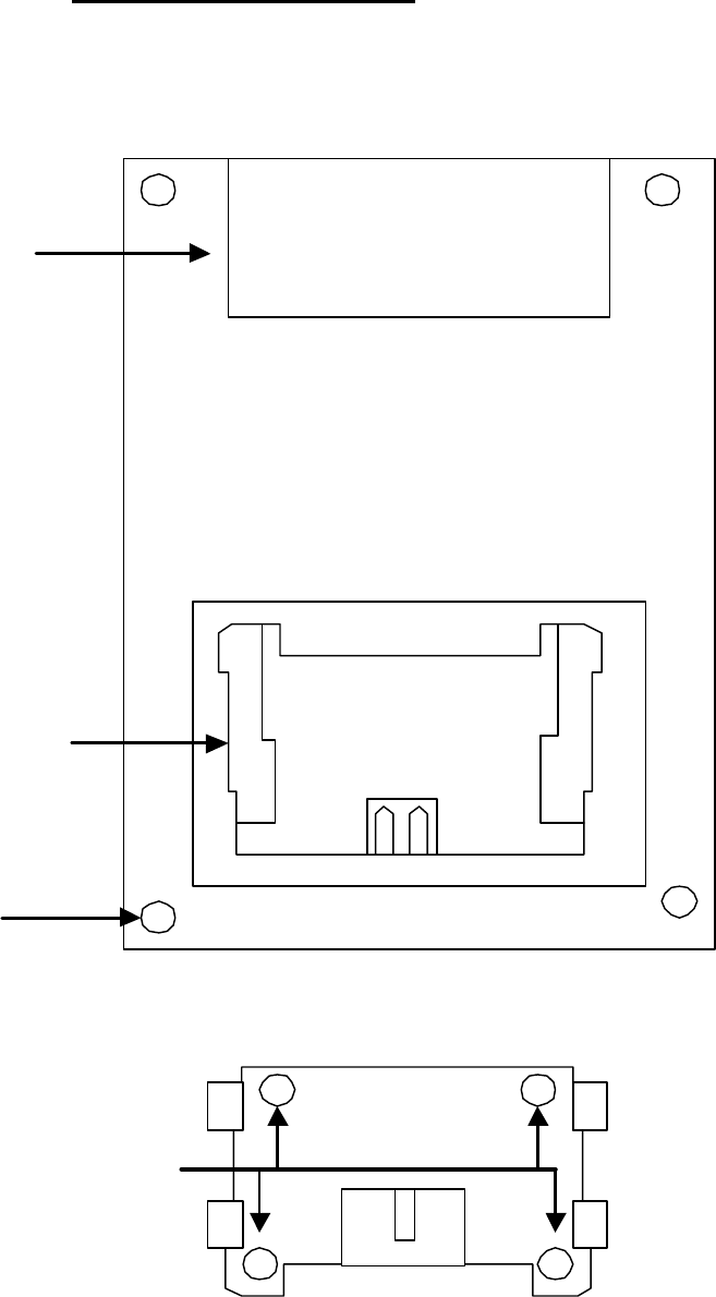
MOUNTING BRACKET
Mounting Holes
Batterey Compartment
Mounting Bracket
Screw Holes
Rear Panel
Refer to page 10 for
battery placement

OPTIONAL EQUIPMENT
STROBE LIGHT
SIDE VIEW FRONT VIEW
The Strobe light can either be mounted to the wall or set on a desk top.
Strobe Light Installation
NOTE: The Strobe Light can be connected to either the HomeWATCH™ Panel or the
Wireless Remote Sounder.
Connecting to the HomeWATCH™ Panel
1.
The HomeWATCH™ Panel should be already installed near the door. The Strobe
Light can be
connected to the HomeWATCH™ Panel using the cable that is
attached to the Strobe Light. The cable is 15 feet long allowing for mounting the
Strobe Light in a location away from the HomeWATCH™ Panel.
2. The Strobe Light should be attached to the wall. Usin
g the back portion of the
Strobe Light box as a template determine where the Strobe Light will be located.
NOTE: The Strobe Light may be mounted either vertically or horizontally. Using
a pencil or pen mark the location of the two mounting holes on the w
all. Drill two
holes with a XXXX drill bit. Place the two anchors provided with the Strobe
Light Kit into the two holes if needed.
3.
Using the two screws provided attach the back panel to the wall. The Strobe
Light box should now snap into the back pa
nel. The Strobe Light cable can now
be connected to the HomeWATCH™ Panel connecting the cable to the blue
connection on the bottom of the HomeWATCH™ Panel.
4.
The Strobe Light will produce a Red light when the HomeWATCH™ Panel goes
into alarm.
Connecting to the Wireless Remote Sounder
1.
Determine where you will be installing the Wireless Remote Sounder first as the
Strobe Light is connected to the Wireless Remote Sounder. There is a 15 foot
cable attached to the Strobe light allowing for mounting the St
robe Light away
from the Wireless Remote Sounder.
5.
The Strobe Light should be attached to the wall. Using the back portion of the
Strobe Light box as a template determines where the Strobe Light will be located.
NOTE: The Strobe Light may be mounted eith
er vertically or horizontally. Using
a pencil or pen mark the location of the two mounting holes on the wall. Drill two
holes with a XXXX drill bit. Place the two anchors provided with the Strobe
Light Kit into the two holes if needed.
Vibrator Installation
NOTE: The
Vibrator is usually connected to the Wireless Remote Sounder to alert the
caregiver that their loved one wearing the HomeWATCH™ transmitter is attempting to
exit the home.
1. The Vibrator comes with an approximately 8 foo
t cable that is connected to the
Wireless Remote Sounder. The Vibrator is connected to the Wireless Remote
Sounder using the BLUE connection on the bottom of the Wireless Remote
Sounder. See Figure XXXXX. The Wireless Remote Sounder must be located
near the bed to utilize this feature of the HomeWATCH
™ Wandering Alarm
System.
2.
The Vibrator is place under the pillow or bed sheet and when the
HomeWATCH™ Panel goes into alarm the vibrator will begin to vibrate.
1.
Using the two screws provided attach the back panel to the wall. The Strobe
Light box should now snap into the back panel. The Strobe Light cable can now
be connected to the Wireless Remote Sounder connecting the cable to the blue
connection on the bottom of the Wireless Remote Sounder.
2.
The Strobe Light will produce a Red light when the HomeWATCH™ Panel goes
into alarm.

LEGEND FOR PACKAGE EXTERIOR—RETAIL SALES
I.
THIS PRODUCT IS SUBJECT TO AN EXPRESS LIMITED WARRANTY STATEMENT
THAT LIMITS THE LIABILITY OF SECURE CARE PRODUCTS, INC. (“SECURE CARE”)
FOR ANY CLAIMS RELATING TO THE INSTALLATION AND USE OF THIS PRODUCT
TO EITHER REPAIR, REPLACEMENT OR A REFUND OF THE PURCHASE PRICE, AT
SECURE CARE’S OPTION. BY INSTALLING AND USING THIS PRODUCT, THE
BUYER WILL BE AGREEING TO THE TERMS OF THAT EXPRESS LIMITED
WARRANTY STATEMENT. THE SELLER OF THIS PRODUCT HAS A COPY OF THAT
EXPRESS LIMITED WARRANTY STATEMENT THAT MAY BE REVIEWED BEFORE
THE BUYER PURCHASES THIS PRODUCT. THE SELLER OF THIS PRODUCT HAS NO
AUTHORITY TO CHANGE THIS EXPRESS LIMITED WARRANTY STATEMENT IN
ANY WAY.
II.
THIS PRODUCT IS DESIGNED TO ASSIST IN MONITORING THE MOVEMENTS OF
ONE OR MORE PERSONS IN CERTAIN LOCATIONS. IT CANNOT PREVENT ANY
PERSON FROM DOING ANYTHING, INCLUDING LEAVING A DESIGNATED
LOCATION OR AREA. IMPROPER INSTALLATION OR OPERATION, INADEQUATE
MAINTENANCE, AND ENVIRONMENTAL FACTORS NEAR
THE INSTALLATION SITE
CAN MAKE THIS PRODUCT ACT DIFFERENTLY FROM OR BE INEFFECTIVE FOR ITS
INTENDED USE. NO PRODUCT CAN ELIMINATE ALL RISK OR ASSURE COMPLETE
SECURITY. SECURE CARE DOES NOT REPRESENT THAT THE INSTALLATION AND
USE OF THIS PRODUCT WILL MAKE ANY PERSON SAFER, LESS LIKELY TO DO
ANYTHING OR PROTECT ANY PERSON’S SECURITY OR HEALTH. THIS PRODUCT
IS NOT INTENDED AS A SUBSTITUTE FOR THE CAREFUL MONITORING OF
PERSONS IN ALL LOCATIONS.
HEADING FOR PRODUCT PACKAGING INSERT—RETAIL SALES:
WARNING: BEFORE INSTALLING OR USING THIS PRODUCT, PLEASE READ
CAREFULLY AND BE SURE YOU UNDERSTAND THE FOLLOWING SAFETY
WARNINGS:

Replacement Parts List
PART PART NUMBER
HomeWATCH Panel A02350900
Power Supply C40000125
Power Supply Cable 15 ft A02350908
Door Contacts
Door Contact Cable 8 ft A02350909
Door Bell
Door Bell Cable 5 ft A02350907
Volume adjustment tool
9V Rechargeable Battery B15360501
OPTIONAL EQUIPMENT
Wireless Remote Sounder A02350905
9 V Rechargeable Battery B15360501
Power Supply C40000125
Power Supply Cable A02350908
Vibrator with cable
Strobe light
Strobe Light Cable 15 ft
HomeWATCH TRANSMITTER
HomeWATCH Transmitter A22350900
Straps C25000516

FCC Compliance Statement
This device complies with Part 15 of the FCC Rules.
Operation is subject to the following two conditions:
(1) This device may not cause harmful interference and
(2) This device must accept any interference received,
including interference that may cause undesired operation
Changes or modifications to this system not expressly
approved by Secure Care Products, Inc. could void the
user's authority to operate the equipment.

Secure Care Products, Inc.
Concord, New Hampshire USA
Compliance
Information
Statement
Conforming Product Name :
135 Non-ID & HW Transmitter
Conforming Model or Part Number :
A21350900 A22350900
Manufacturer and Responsible Party :
Secure Care Products, Inc.
39 Chenell Drive
Concord, New Hampshire 03301 USA
This device complies with Part 15 of the FCC Rules. Operation is
subject to the following two conditions: (1) This device may not cause
harmful interference, and (2) this device must accept any interference
received, including interference that may cause undesired operation.
Michael McHugh Director of Engineering .
Name of Responsible Person Company Title or Position
Authorized Signature
Date: 02/15/06

Secure Care Products, Inc.
Concord, New Hampshire USA
Compliance
Information
Statement
Conforming Product Name :
433.92 MHz HW Sounder Receiver
Conforming Model or Part Number :
A02350905
Manufacturer and Responsible Party :
Secure Care Products, Inc.
39 Chenell Drive
Concord, New Hampshire 03301 USA
This device complies with Part 15 of the FCC Rules. Operation is
subject to the following two conditions: (1) This device may not cause
harmful interference, and (2) this device must accept any interference
received, including interference that may cause undesired operation.
Michael J. McHugh Director of Engineering .
Name of Responsible Person Company Title or Position
Authorized Signature
Date: 02/15/06

Secure Care Products, Inc.
Concord, New Hampshire USA
Compliance
Information
Statement
Conforming Product Name :
HW Transceiver
Conforming Model or Part Number :
A02350900
Manufacturer and Responsible Party :
Secure Care Products, Inc.
39 Chenell Drive
Concord, New Hampshire 03301 USA
This device complies with Part 15 of the FCC Rules. Operation is
subject to the following two conditions: (1) This device may not cause
harmful interference, and (2) this device must accept any interference
received, including interference that may cause undesired operation.
Michael McHugh Director of Engineering .
Name of Responsible Person Company Title or Position
Authorized Signature
Date: 02/15/06

MOUNTING TEMPLATE
USING THE TEMPLATE PROVIDED. TAPE TEMPLATE TO THE WALL IN THE LOCATION
OF WHERE THE HOMEWATCH PANEL WILL BE LOCATED. DRILL FOUR HOLES WITH A
13/64 DRILL BIT. PLACE THE ANCHORS PROVIDE WITH THE KIT IN EACH HOLE
MAKING FLUSH TO THE WALL. USING THE FOUR SCREWS , SCREW THEM INTO THE
ANCHORS LEAVING A LITTLE LESS THAN A ¼ INCH OF THREAD SHOWING. NOW
SLIDE THE HOMEWATCH PANEL ONTO THE SCREWS.
TM